Installation, service and operating instruction Cetetherm AquaFirst Domestic hot water supply
←
→
Page content transcription
If your browser does not render page correctly, please read the page content below
Installation, service and operating instruction Cetetherm AquaFirst

     Domestic hot water supply

DOC1361 – 2021-06-08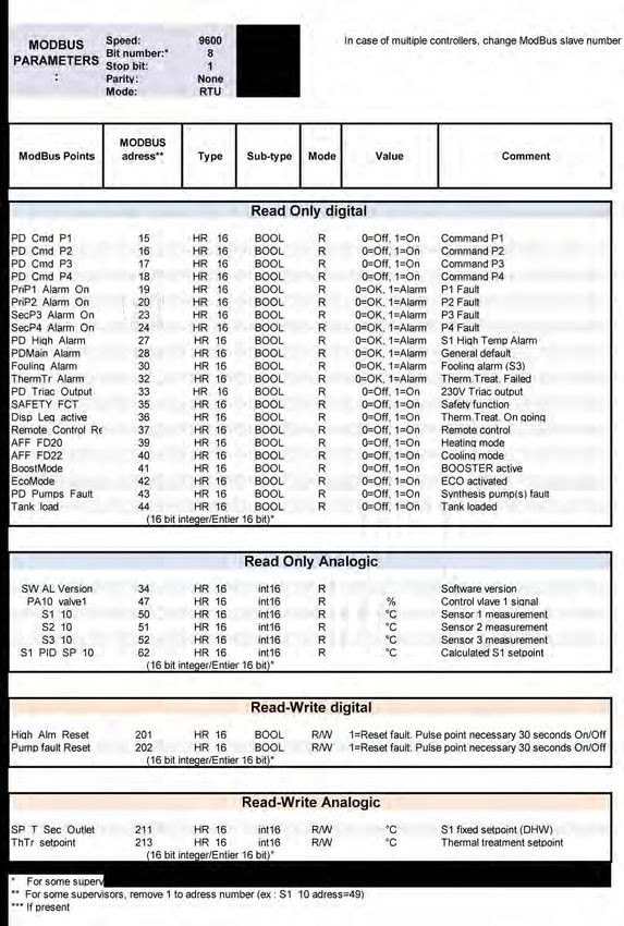
This manual is published by Cetetherm.
Cetetherm can without further notice make changes and improvements to the content in this manual if it is necessary due to printing
mistakes, wrong information or changes in the hardware or software. All these types of changes will be included in future release of the
manual.

Cetetherm AquaFirst
                                                                                                  Installation, service and operating instruction

Contents
1       AquaFirst general presentation ............................................................................................. 3
1.1     Product overview AquaFirst ......................................................................................................................4
2       Operating principle ................................................................................................................. 5
3       Installation ............................................................................................................................... 6
3.1     Unpacking/Preparation/Mounting ..............................................................................................................6
3.2     Commissioning ..........................................................................................................................................6
3.3     Installation of an AquaFirst Direct (Instantaneous) units ..........................................................................7
3.4     Installation of an AquaFirst Indirect (Semi-Instantaneous) unit ................................................................8
3.5     Measure sketch Aqua First 2000 & 4000 Direct version* .........................................................................9
3.6     Measure sketch Aqua First 2000 & 4000 Indirect version* .....................................................................10
3.7     Measure sketch Aqua First 6000 & 8000 Direct version* .......................................................................11
3.8     Measure sketch Aqua First 6000 & 8000 Indirect version* .....................................................................12
4       Electrical installation ............................................................................................................ 13
4.1     Regulator Components ...........................................................................................................................13
4.2     Electrical wiring diagram .........................................................................................................................14
4.3     Wiring details ...........................................................................................................................................15
4.3.1      Power terminal on PCB ......................................................................................................................15
4.3.2      230V 3 points actuator terminals on PCB ..........................................................................................15
4.3.3      Low voltage outputs on PCB ..............................................................................................................15
4.3.4      Low voltage inputs (contacts / Sensors) on controller .......................................................................15
5       User instruction operator control panel Micro 3000 ......................................................... 16
5.1     Home screen ...........................................................................................................................................17
5.2     Command symbols ..................................................................................................................................17
5.3     Setting the time and date ........................................................................................................................18
5.4     Changing the Date format .......................................................................................................................18
5.5     Setting the Daylight Saving Time ............................................................................................................18
5.6     Saving changes .......................................................................................................................................18
6       End user mode ...................................................................................................................... 19
6.1     Set the hot water temperature .................................................................................................................19
6.2     Time programs ........................................................................................................................................19
6.3     Changing time and temperature in a time program.................................................................................20
6.3.1      Special days .......................................................................................................................................20
6.4     Making a Quick temperature change ......................................................................................................21
7       Technician menu, total read and write level ...................................................................... 22
7.1     Login ........................................................................................................................................................22
7.2     The technician Main menu ......................................................................................................................22
7.3     Configuration menu .................................................................................................................................23
7.4     S1 Menu Secondary Outlet .....................................................................................................................24
7.5     Thermal Treatment Menu ........................................................................................................................24
7.6     Safety Function .......................................................................................................................................25
7.7     Eco-Booster Function ..............................................................................................................................25
7.8     Fouling function .......................................................................................................................................26
7.9     230V Triac menu .....................................................................................................................................26
7.10    Pumps Menu ...........................................................................................................................................27
7.11    Autotest menu .........................................................................................................................................28
7.12    Clear alarm menu ....................................................................................................................................29
8       Service Menu                   ................................................................................................................... 30
8.1     Change password for technician level ....................................................................................................30
8.2     Login installer ..........................................................................................................................................30
8.3     Menu Continue ........................................................................................................................................31
8.4     Operating hours .......................................................................................................................................32
8.5     Trending parameters ...............................................................................................................................33
8.6     Display the trend buffer ...........................................................................................................................34
8.7     Point Data ................................................................................................................................................34

                                                                                1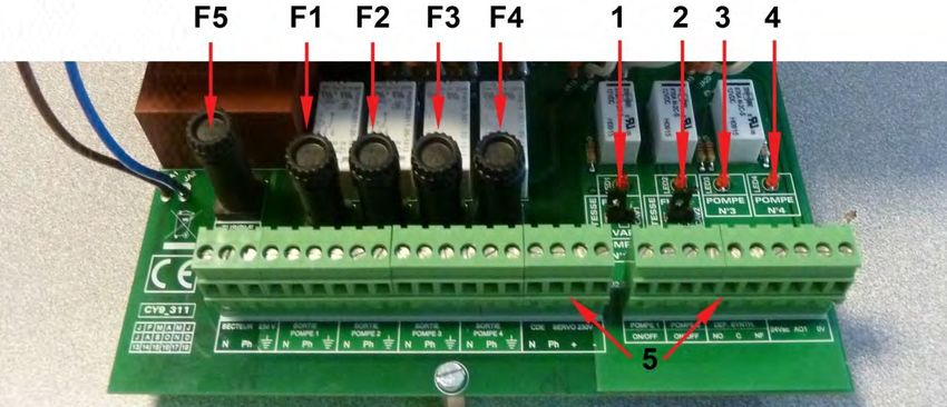
Cetetherm AquaFirst
Installation, service and operating instruction
9 Alarm menu ..................................................................................................................... 35
10 Parameters list ...................................................................................................................... 36
11 Factory RESET ...................................................................................................................... 37
12 Modbus .................................................................................................................................. 38
12.1 Modbus communication ..........................................................................................................................38
12.2 Connecting multiple Micro 3000 control boxes .......................................................................................38
12.3 Change Modbus parameters ...................................................................................................................39
12.4 Modbus slave communication parameters..............................................................................................40
13 Trouble shooting .................................................................................................................. 41
14 Maintenance and repairs ...................................................................................................... 42
14.1 Open the control box ...............................................................................................................................43
14.2 Change fuses ..........................................................................................................................................43
14.3 Pumps’ number .......................................................................................................................................44
14.4 Add a recycling pump to an AquaFirst Direct ..........................................................................................44
14.5 Add an extra pump ..................................................................................................................................44
14.6 Primary pump wiring................................................................................................................................44
14.6.1 Wirings inside pump ...........................................................................................................................44
14.6.2 Pump head setting .............................................................................................................................45
14.6.3 Operating status .................................................................................................................................45
14.7 Add an extra sensor ................................................................................................................................45
14.8 230V Triac output ....................................................................................................................................45
14.9 Relay 1 and 2 contacts ............................................................................................................................45
14.10 Remote Control contact...........................................................................................................................46
14.11 Clean plate heat exchangers...................................................................................................................47
14.12 Technical data .........................................................................................................................................47
14.13 Spare parts-Aqua First 2000 & 4000 .......................................................................................................48
14.14 Spare parts Aqua First 6000 & 8000 .......................................................................................................49
15 Commissioning report ......................................................................................................... 50
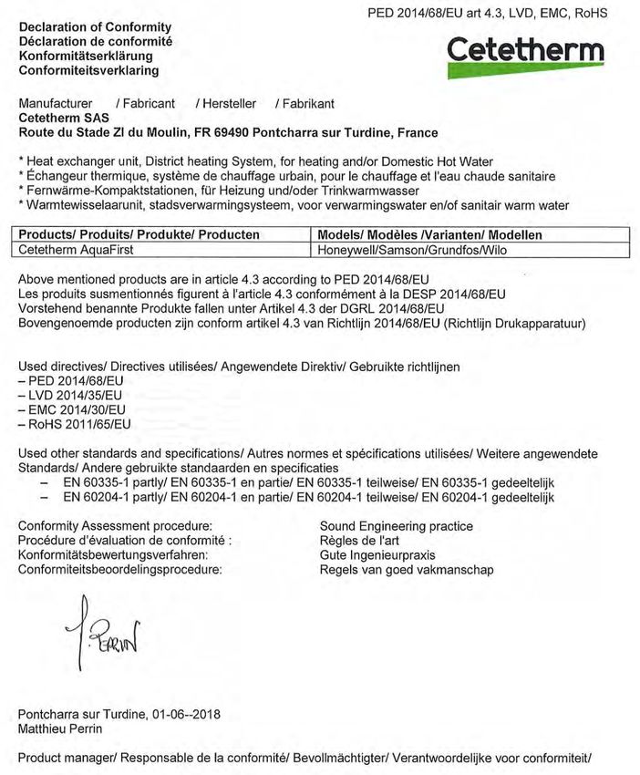
16 Declaration of conformity .................................................................................................... 51
17 Warranty ................................................................................................................................ 52
17.1 How to contact Cetetherm .......................................................................................................................52
2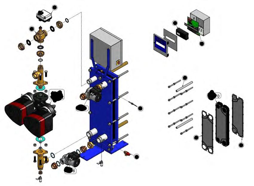
Cetetherm AquaFirst
                                                                    Installation, service and operating instruction

1 AquaFirst general presentation
Cetetherm AquaFirst is a compact tap water system product including a heat exchanger, motorised control
valve and managed primary and secondary pumps, as per versions. It is equipped with a control box including
a dedicated PCB and communicant temperature controller. Piping is made of specially designed brass parts.
AquaFirst has been tested hydraulically and electrically at the factory.

The AquaFirst is available in two plate sizes:
   • M3H for model FI2000 and FI4000.
   • M6M MH/ML for model FI6000 and FI8000.

There are in total 40 models of the AquaFirst, 12 direct and 24 indirect. All types can have single or double
pumps.

Option:
    • rock wool insulation with cladded aluminium sheet

The AquaFirst must be connected to a primary heating source, like a boiler or a heat exchanger. The
secondary side is connected to cold water inlet and to domestic hot water network, see flowcharts for more
details.

The tap water module is designed for indoor installation, for example in a plant room. The ambient temperature
in the room must be min 0°C and max 40°C, max humidity 85% without condensation.

AquaFirst is WRAS approved. This approval demonstrates it is of a suitable quality and standard against the
requirements of the UK Water Supply (Water Fittings) Regulations and Water Supply (Water Fittings)
(Scotland) Byelaws, provided it is installed and used in accordance with the installation and requirement notes
and any other restrictions within the approval. These are available on the WRAS approval directory
https://www.wras.co.uk/search/products/

                                                        3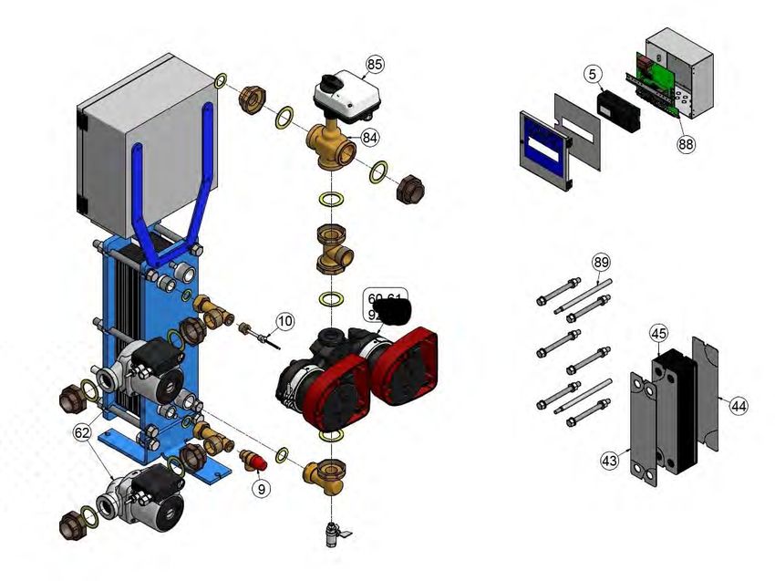
Cetetherm AquaFirst
Installation, service and operating instruction

1.1   Product overview AquaFirst

AquaFirst 2000 & 4000                             AquaFirst 6000 & 8000

Picture 1                                         Picture 2

  1     Control Box including Micro3000            6    Secondary charging pump
  2     Signal actuator                            7    Safety valve
  3     Secondary charging pump                    8    3-port mixing control valve
  4     Temperature sensor S1                      9    Plates Heat Exchanger with
                                                        Insulation (optional)
  5     Primary single or double pump
        (as per version)

                                                   4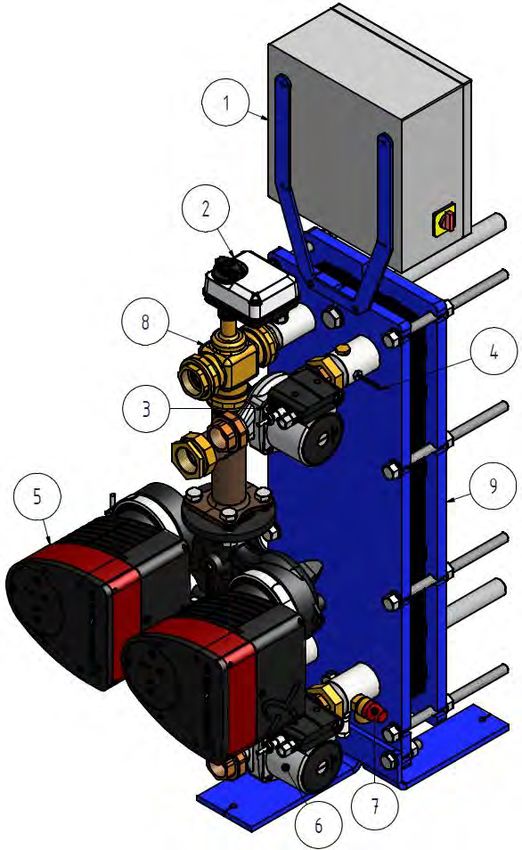
Cetetherm AquaFirst
                                                                   Installation, service and operating instruction

2 Operating principle

Picture 3                            Picture 4                              Picture 5

                                                                            Picture 8
Picture 6                            Picture 7

    •   The primary water enters the 3-port modulating valve (1) and leaves through the fitting (2).
    •   Cold water enters at bottom part (3) and leaves at the required temperature at high part (4).
    •   The secondary circuit should be equipped with a recirculation or a charging pump,
    •   Modules suitable for 230V 1 phase / 50 Hz + Earth,
    •   Make sure power supply in the field corresponds to the above voltage,
    •   A fuse protection should be provided on site.
    •   Relays: Volt Free Contacts (VFCs), 2 Amps maxi, each under 230 V.

                                                       5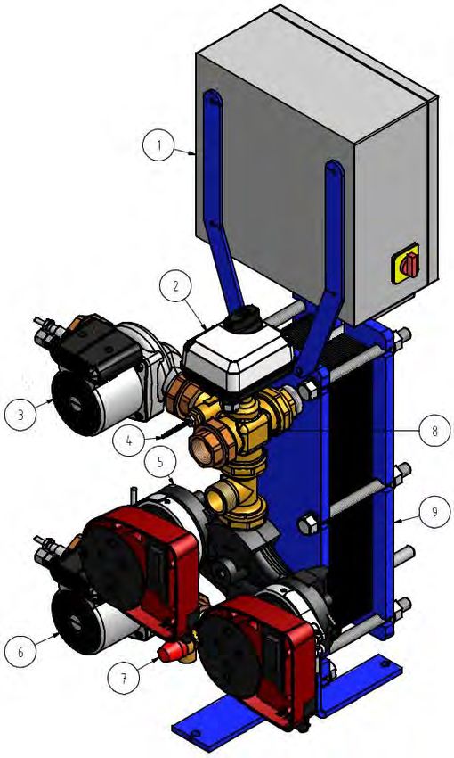
Cetetherm AquaFirst
Installation, service and operating instruction

3 Installation
              The installation work must be carried out by an authorized installation contractor.

              The temperature and the pressure of the water are very high. Only qualified technicians are
              allowed to work with the AquaFirst. Incorrect operation may cause serious personal injury and
              result in damage to the building.

              Minimum pressure/temperature on primary side: 1.0 bar/ 2°C, 1.5 bar / 110°C

              Maximum pressure/temperature on primary side :10 bar /110°C

              Maximum pressure on secondary side: 10 bar/ 100°C

3.1   Unpacking/Preparation/Mounting
• Rinse the pipes, before connecting them to the tap water module.
   Pipe works may contain solid particles that could block or prevent the modulating valve to operate correctly.
• Pipe the primary and the secondary of the module.
• Fill-up both sides progressively with water.
• Purge air at high parts.
• Purge all the pump bodies.
• Switch the power on.
• Check controller setting and enable the required functions.

3.2   Commissioning
Before installation this manual must be read.

The controller has been set at the factory. If any function needs tuning, values can be changed with reference
to this manual for parameter setting. Initially, the commissioning process should be carried out with the factory
settings.

Fill out the form in chapter 15 Commissioning report.

                                                        6
Cetetherm AquaFirst
                                                                  Installation, service and operating instruction

3.3    Installation of an AquaFirst Direct (Instantaneous) units
The tap water modules should be installed according to the following schematics.

Picture 9
REP     DESIGNATION                                    REP    DESIGNATION
 A      Primary inlet                                  HE     Heat Exchanger (PHE)
 B      Primary Outlet                                  PP    Primary pump (single/double)
CW      Cold water inlet                               PR     Recycling pump (option)
V3V     Mixing 3 port control valve with actuator       V     Manual gate valve
PRV     Pressure relief valve                           S1    DHW temperature sensor (master)

The primary water tank limits available generator capacity.

Picture 10

                                                       7
Cetetherm AquaFirst
Installation, service and operating instruction

3.4    Installation of an AquaFirst Indirect (Semi-Instantaneous) unit

               Recycling flow rate PR must be < 60% PC flow rate.

Protect the storage tank by installing the added safety valve. Pressure gage=tank MAX working pressure and
can be different from tap water module’s safety valve pressure gauge. The safety vaIve protects the storage
vessel and not the tap water system.
Secondary charging pumps have the following limitations as per water quality:
pH 6 to 9 and TH
Cetetherm AquaFirst
Installation, service and operating instruction
3.5 Measure sketch Aqua First 2000 & 4000 Direct version*
Picture 12
* Pump type, single or double
9Cetetherm AquaFirst
Installation, service and operating instruction
3.6 Measure sketch Aqua First 2000 & 4000 Indirect version*
Picture 13
* Pump type, single or double
10Cetetherm AquaFirst
Installation, service and operating instruction
3.7 Measure sketch Aqua First 6000 & 8000 Direct version*
Picture 14
* Pump type, single or double
11Cetetherm AquaFirst
Installation, service and operating instruction
3.8 Measure sketch Aqua First 6000 & 8000 Indirect version*
Picture 15
* Pump type, single or double
12Cetetherm AquaFirst
Installation, service and operating instruction
4 Electrical installation
Power supply the control box with 230V 50 Hz + Earth, using electric protection in the main
electric power box. Micro 3000 box is a secondary electrical control box.
Human protections and protection against short circuits and over intensity must be installed in the
main electric box.
4.1 Regulator Components
Picture 16
1 Controller, Micro 3000 3 Power Supply
2 Main switch 4 Printed Circuit Board
13Cetetherm AquaFirst
Installation, service and operating instruction
4.2 Electrical wiring diagram
NOTE: When the remote-control contact is open, the unit operates normally. If it is closed the unit is in standby.
Picture 17
Earth or Ground wiring on the PCB IS MANDATORY. It must be connected to terminal No.3.
Remote contact:
If contact closed, the unit is in standby mode. If contact open, the unit is operating normally.
14Cetetherm AquaFirst
Installation, service and operating instruction
4.3 Wiring details
4.3.1 Power terminal on PCB
1 2 3 4 5 6 7 8 9 10 11 12 13 14 15
N Ph ╧ N Ph ╧ N Ph ╧ N Ph ╧ N Ph ╧
230V Main Pump 1 Pump 2 Pump 3 Pump 4
Power supply (Primary) (Primary) (Secondary) (Secondary)
Control box power supply: 230V 50Hz + Ground terminals 1,2 and 3.
Terminals 4 to 15 are dedicated to P1, P2, P3, P4 230V power supply.
Do not exceed 3A per pump.
4.3.2 230V 3 points actuator terminals on PCB
16 17 18 19
N Ph + -
230V 3 points actuator
Opening of the actuator is made sending 230V pulses between terminals 16 (N) and 18 (+).
Closing of the actuator is made sending 230V pulses between terminals 16 (N) and 19 (-).
Terminal 17 (permanent Phase) can be used with return to zero (RTZ) actuators.
3 points 230V and 0-10V signals (or pulses) are sent continuously even if they are not wired.
4.3.3 Low voltage outputs on PCB
20 21 22 23 24 25 26 27 28 29
0V S/S 0V S/S NO C NC 24Vac AO1 (0-10V) 0V
Pump 1 Pump 2 Relay 1 contact 0-10V DC actuator, 24V AC 5VA power
Start / Stop Start / Stop NO or NC to supplied
N/A N/A choose 0V is common on both signals
4.3.4 Low voltage inputs (contacts / Sensors) on controller
31 33 35 36 37 40 41 42 46 47
GND Bi1 Ipso Ipso GND UI1 UI2 UI3 Ipso Ipso
P3 P4 S1 S2 S3 P1 P2
Remote Secondary Temperature Secondary
Common Contact* pump(s) default Common sensor(s) pump(s) default
input contact(s)* input(s)* input contact(s)*
*For each of these inputs / outputs, the second wire must be connected to the common terminal
37 or 31 as per available space.
There is no polarity on all contacts and temperature sensors.
Temperature sensors’ inputs except S1 are already wired. To add a temperature sensor, remove
existing wire from the terminal and isolate its end. Connect the sensor’s wire instead and its
second wire to common terminal, 31 or 37.
15Cetetherm AquaFirst
Installation, service and operating instruction
5 User instruction operator control panel Micro 3000
Picture 18
Button Function
Rotary button for scrolling through the menus. Access sub-menus and change settings
by pressing it.
To activate the line or change a highlighted value, simply press the wheel.
Works like an Enter key.
Press to exit a level and return to the previous menu/parameter.
Works like an ESC key.
Press to access the maintenance / monitoring menu.
NOTE: Requires a password.
Press to go to the Home screen, Main Menu
Press to access the Alarm Menu.
Not used
Not used
Relay 1 activated. By default set to General Default. The parameter is set in the
Configuration menu.
Relay 2 activated. By by default set to High temp Alarm. The parameter is set in the
Configuration menu.
Active data transmission
Active data reception
Alarm indicator
The Control box is switched on.
16Cetetherm AquaFirst
Installation, service and operating instruction
5.1 Home screen
When starting up the Micro 3000 controller the Home Screen menu displays on the screen.
Picture 19
1 Date / hour 4 Access level:
Locked=restricted
Key= total (3333)
2 DHW temperature 5 Command symbols
3 DHW Set point
The controller has password protection, allowing accesses to different menus.
• End user level- requires no login. Marked with a locker in the upper right corner.
• Technician level- access to all menus requires login. Marked with a key in the upper right corner.
NOTE: if there is an ongoing alarm when starting up the AquaFirst, an alarm text will be displayed on the
screen. Press the House button to enter the Home screen.
5.2 Command symbols
Auto
Datapoint is in automatic operation and can be switched into manual operation.
Manual
Datapoint in manual operation and can be switched into automatic operation.
Today function
Datapoint value can be overridden for a particular time period within the next 24 hours.
Datapoint must have a daily time program assigned.
Time Program
Datapoint has a daily time program assigned. Daily time program can be selected and edited.
Edit
Item (datapoint, time program etc.) can be edited.
Add
Item (datapoint, time program etc.) can be added to a list e.g. datapoint can be put to a list of
trended datapoints.
Deleted
Item can be deleted
Enable/disable
• Checked: item is enabled
• Unchecked: item is disabled
17Cetetherm AquaFirst
Installation, service and operating instruction
5.3 Setting the time and date
1. Turn the wheel anticlockwise to highlight the line with time and
date at the top of the screen. Press the wheel to enter the
Date/Time menu.
2. Press the wheel to change the first variable, the year.
3. When the year flashes, increase or reduce the set value by
rotating the wheel.
Once the right value is displayed, press the wheel to confirm the
setting. Next parameter to change starts to flash.
4. Proceed in the same way to set the month, date
and time (hour: minute).
5.4 Changing the Date format
In the Date/Time menu the date format can be changed.
Choose between the following formats:
• yyyy-mm-dd
• mm-dd-yyyy
• dd-mm-yyyy
• dd.mm.yyyy
• dd/mm/yyyy
5.5 Setting the Daylight Saving Time
Summer time
Changing between summer/winter time can be automatic or turned off.
You can also define the dates for changes if they are altered.
The default settings for summertime is:
Last Sunday in March to last Sunday in October.
5.6 Saving changes
Once a value has been changed and confirmed by pressing the wheel, the corresponding change will be
immediately updated.
Press the or to return to the home screen.
18Cetetherm AquaFirst
Installation, service and operating instruction
6 End user mode
The following changes can be done in end user mode:
• Settings which are identical/different for each day of the week at defined times
• Normal temperature(s)
• Lower temperature(s)
• Special period of defined duration during the current year
• One time temperature change at a specific time.
6.1 Set the hot water temperature
Please set a hot water production temperature in line with current national legislation and recommendations
(UTD, Standards EN, ISO etc.)
All countries have different rules for how hot or cold tap water should be.
Cetetherm recommends the hot water temperature is at least 55°C and a hot water recirculation not less than
50°C.
At a temperature below 50°C there is a risk of bacterial growth.
Note that at temperatures above 60°C the risk of scalding increases.
Set points above 63°C result in an increased risk of precipitation of lime scaling on the surfaces of the heat
exchanger.
6.2 Time programs
The time programs used in AquaFirst are adjusted the same way.
Time programs:
• SP_T_Sec_Outlet, to be found in the menu S1 Menu Secondary Outlet. It is to set the DHW temperature
• ThTr_Activated to be found in Thermal Treatment Menu, to activate a thermal treatment (1 sensor mode).
• Multi_P to be found in 230V Triac menu, to activate the 230V power output on the controller
The time program has two different temperature modes, week-temperature or weekend-temperature.
Define for each day of the week which mode to use.
By default has the weekend-temperature mode the same settings as the week-temperature mode.
It is even possible to customize the temperature programs with special dates (holidays periods or free days).
Each temperature mode can have several different times set per day. For each time a different temperature can
be selected that are then in effect until the next time occurs. If only one time is set, the program will run with the
selected temperature.
19Cetetherm AquaFirst
Installation, service and operating instruction
6.3 Changing time and temperature in a time program
By default, the DHW set point SP_T_Sec_Outlet, set to 60°C by default, at any time, all the days of the week.
Add extra temperature set points at different times of the day.
These changes will be reported to all days with the time program week, excluding the time program; weekend.
1. Use the wheel and mark the clock logo. Press the wheel.
2. Mark the day you want to change.Press the wheel.
Now you can choose to:
a) Change a time or temperature.
Mark the line and press the wheel. Change the value by turning the
wheel.
Confirm the new setting by pressing the .
b) Add a new time or set point; choose .
c) To delete a time or set point; choose; .
In this example the set point is 60°C at 22h00.
You can choose to reduce the temperature during the night, in this example
the night temperature is set to 55°C.
6.3.1 Special days
Exception days, so called special days, can be defined. The calendar in the
controller controls the exceptions that can be selected in the Time program.
Exception days override the weekly schedule.
In the Main screen menu, mark ‘Spcl.Days’ and press the wheel.
Choose between:
• Annual - holiday periods where you have to specify beginning date,
end date and DHW set point. This mode is applicable to schools,
offices and so on.
• Bank Holiday - special days during the year where set points can be
different ex: Christmas, New Year.
• Daily programs - particular days where you want to change the
temperature set point.
20Cetetherm AquaFirst
Installation, service and operating instruction
6.4 Making a Quick temperature change
You can quickly define a “one time” temperature change, a period of the day with a different setting. When the
change period has expired, the temperature set point goes back to standard time schedule program.
1. In the home-screen, mark the hourglass icon and choose it, by
pressing the wheel.
2. Define the starting and ending time, and the temperature set point
value.
21Cetetherm AquaFirst
Installation, service and operating instruction
7 Technician menu, total read and write level
In the technician menu you can:
• make settings for the secondary outlet temperature
• enable/disable functions like Eco, booster, thermal treatment
• enable/disable the fouling function (option)
• start an auto test
• clear alarm.
You need to be logged in to:
• see all submenus and change pre-set values
• have full read and write access in the technician menu
7.1 Login
1. Mark the lock in the upper right corner of the screen and press the wheel.
2. Enter: 3333, to access the technician level.
NOTE: You will be automatically logout after ten minutes if no data has been entered.
7.2 The technician Main menu
To enter the Main menu you press the key.
The grey marked parameters or menus are not available in the AquaFirst application.
Their value does not have any impact on the AquaFirst.
Main Menu
T_Secondary_Out Read Only Measured temperature DHW
S1_PID_Setpoint Read Only DHW temperature setpoint
T_Secondary_Inlet Read Only N/A
T_Primary_Outlet Read Only The temperature measured by S3 (option)
T_Primary_Inlet Read Only N/A
T_Recovery1 Read Only N/A
T_Recovery2 Read Only N/A
T_Outdoor Read Only N/A
Configuration Sub Menu See 7.3 Configuration menu
S1 Menu Sec.Outlet Sub Menu See 7.4 S1 Menu Secondary Outlet
S2 Menu Sec.Inlet Sub Menu N/A
Delta T (S3-S2) Sub Menu N/A
S4 Menu Prim Inlet Sub Menu N/A
S5 Menu Outdoor T Sub Menu N/A
Thermal Treatment Sub Menu See 7.5 Thermal Treatment Menu
SAFETY Function Sub Menu See 7.6 Safety Function
Eco Booster Fcts Sub Menu See 7.7 Eco-Booster Function
Fouling Function Sub Menu See 7.8 Fouling function
Pumps Menu Sub Menu See 7.10 Pumps Menu
Solar Menu Sub Menu N/A
Aquaprot_Heating N/A N/A
230V Triac Menu Sub Menu See 7.9 230V Triac menu
Auto Test Sub Menu See 7.11 Autotest menu
Clear Alarm(s) Sub Menu See 7.12 Clear alarm menu
22Cetetherm AquaFirst
Installation, service and operating instruction
7.3 Configuration menu
NOTE: After resetting the controller, this sub menu should be accessed to configure pumps’ number.
Parameter Factory Optional setting Description
Setting
Type 0= First 1=Eff 0 0= AquaFirst Set to 0
1= AquaEff
S5 Active heating 0 0 Disables / Set to 0
1 Enables heat
curve
Cooling Mode AO1 0 0=Heating/ Set to 0
1=Cooling mode
P12 Nbr of Pumps 0 0/1/2 Primary pump(s) number
MinSpeedP1P2 40 10 >100 N/A
P34 Nbr of Pumps 0 0/1/2 Secondary pump(s) number
Modbus Factor 1 1/10/100 To set displayed decimals on Modbus
values.
1=integer value, eg:58°C
10=1 decimal, e.g. 583/10=58,3°C
100=2 decimals, e.g. 5836/100=58,36°C
Relay 1 function*) 1 0..7 0=No action
1=General Default (GD)
2=High temp Alarm (HA)
3=Eco function (E)
Relay 2 function*) 2 0..7 4=Booster function (B)
5=Thermal Treatment (TT)
6=Pump Fault (PF)
7=Tank loaded (TL)**.
**Requires sensor S2.
Renewable Config Keep 0 N/A N/A
APilot rev 0=Off 1=On Keep 0 N/A N/A
SP distrib 0=I 1=E 0 N/A N/A
SW AL Version xx N/A Firmware Version
*)
Both relay 1 and 2 are programmable.
23Cetetherm AquaFirst
Installation, service and operating instruction
7.4 S1 Menu Secondary Outlet
Parameter Factory Optional setting Description
Default
Setting
SP_T_Sec_Outlet 60°C DHW Setpoint Change setpoint value in clock program
Delta T S1 HiAlm 10°C 0-50 High Temperature Alarm if Ts1
SP_T_Sec_Outlet+Delta Ts1 HiAlm
High T Alarm Delay 1 min 0-30 High temp alarm is effective after this
temporisation
High Alarm Auto Reset 0 0/1 0=MANUAL alarm clear /
1=AUTO alarm clear
High_Alm_Reset Off Off/On Put ON to clear an high temp alarm,
then put Off
P_Band AquaFirst 40 0Cetetherm AquaFirst
Installation, service and operating instruction
7.6 Safety Function
This function activates the four pumps' power relays at the same time without considering ipsothermic contacts'
inputs.
NOTE: This function can be enabled from base access level.
Parameter Factory Default Setting Optional Setting
SAFETY_Speed 75% Not used
SAFETY FCT Off Off/On
In case of high temperature alarm on S1, the primary pumps are stopped, even if the function is
activated.
7.7 Eco-Booster Function
One or both functions can be activated at the same time.
• ECO: When control valve is sufficiently closed (Valve Hysteresis) during a sufficient long time (ECO
delay), primary pump switches off and primary mixing valve close down.
The system is switch ON when S1 temperature has gone down more than the set value of
”Eco Hysteresis”.
If secondary pumps are connected (SS/DS/DD series) they are still in operation during the Eco
function.
• Booster: If DHW temperature is dropping down faster than "Booster Gradient", the second primary
pump (if existing) is energized, to increase the primary flow rate. Function stops when DHW
temperature is back to the setpoint value and after "Booster Delay" parameter.
Parameter Factory Setting Optional setting Description
0:- 0 0/1/2/3 0 = No function
1:E 1 = Eco Function only
2:B 2 = Booster function only
3:E+B 3 = Accumulated two functions
Fct_Selection Normal Normal/Eco/Boost/ Playback function selected in
EcoBoost 1:Eco 2:Booster 3:ECoBoost
Eco Delay 5 min 1-30 min Scan time before activating function if
possible
Eco Hysteresis 5°C 1-20°C Temperature range in which the function is
applicable
Valve 10% 0-80% Maximum opening of the valve before
Hysteresis. switching function
Booster Delay 2 sec 2-200 sec Time delay between the Booster functions
stops and the second pump stops
Booster 2°K/s 1 to 20°K/sec Minimum temperature fall speed at which
Gradient the function operates
25Cetetherm AquaFirst
Installation, service and operating instruction
7.8 Fouling function
Fouling function can be activated when the sensor S3 is connected.
Accessing the fouling-menu requires login at Technician level.
If the temperature in S3 is too high for a long time this function activates an alarm that consider the heat
exchanger fooled.
Parameter Factory Default Optional setting Description
Setting
Fouling alm 0 0/1 0=disabled / 1=enabled
activ
Fouling_alarm Normal/Default Read only
SP_Fouling 65°C 60-80 Depends on the HE type and Primary
inlet temperature
7.9 230V Triac menu
Accessing the 230C Triac-menu requires login at Technician level.
This menu allows using a 230VAC Triac output.
Parameter Factory Default Optional setting Description
Setting
Multi P Off Off / On Enable or Disable the
230V output as per clock program
Pulse Duration 5 sec 1-3600 230V pulse duration in seconds
Bypass 0=Off N/A N/A N/A
1= ON
DeltaT Bypass N/A N/A N/A
The 230V electrical output can be configured as a pulse
function. For example, it can be used to shortly activate
an electrical drain valve.
In this configuration, the pulse duration can be
programmed to be active a day, week or special day.
For example, each Sunday at 10h00 for 5 seconds.
Connected device must not exceed 230VAC 1A.
Picture 20
26Cetetherm AquaFirst
Installation, service and operating instruction
7.10 Pumps Menu
P1 and P2=Primary pumps
P3 and P4=Secondary pumps
Parameter Factory Default Optional Description
Setting setting
P1P2 Diff.work time 12 hrs 1 - 1000 hours P1 or P2 Working time
P1P2 Cycling.Type 2 0=Fixed time 0 : See P12 Permut Hour
1=Fixed time+ 1 : If diff reached at this time, pump shift
diff.work time
2=Immediately 2 : Don't care of permutation day+hour
after Diff.hrs
P1P2 Cycling.Period 0 0=None
1=Daily
2=Weekly
3=Monthly
P1P2 Cycling day 1 From 1st to Available only if “P12 Cycling Period” =3”
31st
P1P2 Cycling Hour 10h00 pm 00h00 - 23h59 Pump shift time
(11h59 pm)
Min Speed P1P2 40 10->100 N/A
P1P2 Overlap 6 0-10 seconds Time to start P2(P1) before stopping P1(P2),
to let the other pump start
P3P4 Diff.work time 12 hrs 1 - 24 hours P3 or P4 Working time
P3P4 Cycling Type 2 0=Fixed time 0 : See P34 Cycling Hour
1=Fixed time+ 1 : If diff reached at this time, pump shift
diff.work time
2=Immediately 2 : Don't care of Cycling day+hour
after Diff.hrs
P3P4 Cycling Period 0 0=None
1=Daily
2=Weekly
3=Monthly
P3P4 Cycling day 1 From 1st to Available only if “P34 Cycling Period=3”
31st
P3P4 Cycling Hour 10h00 pm 00h00 - 23h59
(11h59 pm)
P3P4 Overlap 6 0-10 seconds Time to start P4(P3) before stopping P3(P4),
to let the other pump start
Pump_Fault_Reset Off Off/On To clear a pump default, set to On, then Off
27Cetetherm AquaFirst
Installation, service and operating instruction
7.11 Autotest menu
Accessing the Autotest menu requires login at Technician level.
This submenu allows testing analog (contacts) and digital (0-10V) outputs that manage pumps start/stop, both
programmable relays, 230V Triac output and valve’ signal. It is possible to run an automatic sequence or to test
manually each output individually.
In case of Auto test (automatic sequence), it is possible to reduce or increase tests’ temporizations. Pump,
valve and relays test times can be adjusted individually. The time test value will impact on the total auto test
time sequence.
Parameter Factory Optional Setting Description
Setting
Start AutoTest 0 0/1 Set 1 to start auto test. When finished, the value
goes back to zero.
Pump_Fault_Reset Off Off/On Set to On after an Auto test.
Pump time test 4 sec 1-600 sec Not used
Valve time test 4 sec 1-600 sec Temporisations to adjust test duration.
Alarm time test 4 sec 1-600 sec Relays 1 and 2 test
Cmd_P1 On/Off On/Off Activates pump 1 relay
Cmd_P2 Off/On On/Off Activates pump 2 relay
Speed_P1P2 xx % 0-100 % Not used
Cmd_P3 On/Off On/Off Activates pump 3 relay
Cmd_P4 Off/On On/Off Activates pump 4 relay
Speed_P3P4 xx % 0-100 % Not used
Relay 2 Off On/Off Activates relay 2
Relay 1 Off On/Off Activates Relay 1
Triac_Output Off On/Off Activates 230V triac output
Valve signal xx % 0-100 % Valve opening/closing
Valve2 signal xx % 0-100 % N/A
Valve_DO xx % 0-100 % N/A
28Cetetherm AquaFirst
Installation, service and operating instruction
NOTE ! Once test is manually done and finished, remember to put the point on Automatic mode, logo .
NOTE: A pump fault may occur after Auto test. In this case, clear the alarm according to 7.12 Clear alarm
menu.
7.12 Clear alarm menu
Accessing the Clear Alarm menu requires login at Technician level.
All alarms are cleared the same way.
Parameter Factory Optional Setting Description
Default
Setting
High_Alm_Reset Off Off/On Select On to clear the alarm, then return to Off
or wait a few seconds for automatic return to
Off
Pump-Fault_Reset Off Off/On Select On to clear the alarm, then return to Off
or wait a few seconds for automatic return to
Off
29Cetetherm AquaFirst
Installation, service and operating instruction
8 Service Menu
Press the key to enter the Service menu. In the service menu you can:
• change password for technician level
• trending parameters
• display the trend buffer
• check operating hours.
From Point Data sub-menu you can, read or change binary or analog outputs to start/stop a pump, open/close
control valve for example.
8.1 Change password for technician level
NOTE: To change the password you need the password for the Technician level, level 3.
1. Press key to access to Service Menu, go to “Login Installer”,
press the wheel.
2. Enter the current password, press the wheel to validate.
3. Mark “Change Password” then press the wheel.
4. Go to Level 3 line and then click on the password to change it.
Press the wheel to validate.
NOTE: Level 2 password is not in use.
8.2 Login installer
Login Installer **** Enter 3333 if not in technician
mode
Change password
30Cetetherm AquaFirst
Installation, service and operating instruction
8.3 Menu Continue
Menu Sub-menu Sub-menu Description
Continue Operating hours Viewing operating hours of internal
parameters
Trending Points in trend Select variables to trend for
example temperature sensors
Display Trend buffer View the records
Interface Config C-Bus active Factory pre-set
(com) Ctr# Factory pre-set
B-port 9600 Factory pre-set
Append bus number to Activated
data point name
RF Teach in (N/A) Factory pre-set
Modbus Device ID: 10
Baud Rate: 9600
Parity: None
No.stop bits: 1
Time Program Solar Not used
Main It is SP_T_Sec_Oulet (main
temperature program).
See 7.4 S1 Menu Secondary Outlet.
TSP_Amb Not used
Multi Pulse See 7.9 230V Triac menu
Therm. treatment See 7.5 Thermal Treatment Menu
Point Data Internal parameters +I/O visualisation
Analog input Sensor values
Pseudo Analog Can be set points or internal
parameters
Analog Output Valve output signal
Binary input Ipsothermic contacts from pumps,
remote contact
Pseudo Binary Internal flags
Binary Output Pump start/stop contacts, relays
contacts, 230V Triac
Totalizer N/A
Remote Analog N/A
Remote Binary N/A
System Data System informations
Parameters N/A
Date/Time Clock settings
System Info Hardware/Software info (version,
date)
Interface Config Access to Modbus parameters
DDC Times Program's time constant
Flash memory Info on flashing. Allows saving all
settings. It can be reloaded after a
Reset
31Cetetherm AquaFirst
Installation, service and operating instruction
8.4 Operating hours
Operating hours for the following variables can be checked:
• Therm_Protec_P1/P2/P3/P4 • AFF_leg_active
• Cmd_P1/P2/P3/P4 • SAFETY_FCT
• Main_Alarm • Multi_P
• High_Temp_Alarm • ThTr_Activated
• ECO • Booster
For more information and description see 10 Parameters list.
1. Press key to access to Service Menu, then click on “Continue”.
2. Select “Operating Hours” in the menu.
The first time you enter this menu, the list is empty.
3. To add a variable to trend; choose .
4. Mark one variable to follow and press the wheel.
5. Validate the variable by ticking in the Operating Hours box. If this box is
empty the variable is in the list but it is not recorded.
When you go back in the menu ( key), you can see the list with “Cmd_P1”
parameter, and on the right side, the operating hours.
For more details, click on the line to open the sub-menu.
Here you can read that P1 has been operating less than 1 hour, has been
switched one time and status is On.
Proceed the same way to add extra variables.
32Cetetherm AquaFirst
Installation, service and operating instruction
8.5 Trending parameters
A lot of different variables can be recorded or trended. It can be temperatures’ measurement, valves or pumps’
signals, ipsothermic contacts, alarms, thermal treatments etc.
1. Press key to access to Service Menu, then click on “Continue.
2. Select “Trending” in the menu
3. Select “Points in Trend”.
The first time you enter this menu, the list is empty.
4. To add a variable to trend; choose .
5. Mark the variable to follow and press the wheel.
In this example the Secondary outlet temperature, S1.
6. Validate the variable by ticking in the Trend Log box. If this box is
empty the variable is in the list but it is not record.
There are two different ways to record:
a) Only the temperature change is recorded. This saves memory and
allows a longer sampling period compared to method 2.
Select the record hysteresis. In our case, every 1°C temperature
change is recorded. You can change the hysteresis value by clicking
on it.
b) Record on a time base, whatever the temperature changes or not.
Note that this method consumes memory, especially if a short time
base is selected. Here is the time base selected to 10 minutes
recording (1 record every 10 minutes).
For method a set “Trend cycle” to zero, for method b, set “Trend Hyst” to zero.
33Cetetherm AquaFirst
Installation, service and operating instruction
8.6 Display the trend buffer
1. Press key to access to Service Menu, then click on “Continue”.
2. Select “Trending” in the menu.
3. Select “Display Trend Buffer”.
4. Select the variable to display, S1 in this case, and press the wheel.
Date, time and temperature at the time can be read.
For example on 21st of September at 14h22 was the temperature in S1 58°C.
8.7 Point Data
From the menu Point Data, it is possible to start/stop a pump, open/close the control valve for example.
This menu includes
• read or change analog inputs
• read or change digital inputs
• read or write digital outputs (start and stop a pump)
• read or write analog outputs (open or close control valve for example).
NOTE ! Once test is manually done and finished, remember to put the point on Automatic mode, logo .
34Cetetherm AquaFirst
Installation, service and operating instruction
9 Alarm menu
Alarm indication: Is volt Free Contacts (VFCs), 2 Amps maxi, each under 230 V.
Press key to access to Alarm menu. The menu contains four different lists:
• Alarm Buffer
Lists all events with; date, time and type of event.
• Points in Manual
List of all points actually in manual mode this list should be empty. When point values are forced for
tests for example, they should be place in automatic mode at the end.
• Points in Alarm
Lists all events with alarm condition.
• Critical Alarms
Lists all alarms with critical alarm condition.
Critical alarms are important alarms, like high temp.
• Non-Critical Alarms
Lists all non-critical alarm condition.
These alarms are more information, like power failure.
For example, in the alarm buffer you can read:
15:52 SAFETY_FCT
15:51 SAFETY_Speed
15:41 SAFETY_Speed
15:40 SAFETY_FCT
Note that the alarms are listed with the latest at the top.
Press a line to see more information about the alarm.
Displayed Meaning
19-06-2012 15:52 SAFETY_FCT On Auto operation The safety function has been set to auto mode,
stopping the safety function at 15h52.
19-06-2012 15:51 SAFETY_Speed 100% Auto The safety speed has been set in Auto mode at
operation 100% at 15h51.
19-06-2012 15:41 SAFETY_Speed 75% Manual The speed pump has been set manually to 75%
operation at 15h41.
19-06-2012 15:40 SAFETY_FCT On Manual Operation The safety function has been activated manually
the 19th of June 2012 at 15h40.
35Cetetherm AquaFirst
Installation, service and operating instruction
10 Parameters list
There are more than 100 different variables used in the controller. Most of them are used for internal programs
and calculations. Here we describe the main points.
Name Description Unit Modbus
Address*
Therm_Protec P1 Ipsothermic input from P1 pump 0/1 11
Therm_Protec P2 Ipsothermic input from P2 pump 0/1 12
Therm_Protec P3 Ipsothermic input from P3 pump 0/1 13
Therm_Protec P4 Ipsothermic input from P4 pump 0/1 14
PD_Cmd_P1 P1 command. It is the pump Start/Stop output On/Off 15
PD_Cmd_P2 P2 command. It is the pump Start/Stop output On/Off 16
PD_Cmd_P3 P3 command. It is the pump Start/Stop output On/Off 17
PD_Cmd_P4 P4 command. It is the pump Start/Stop output On/Off 18
PriP1_Alarm_On Primary pump 1 default 0/1 19
PriP2_Alarm_On Primary pump 2 default 0/1 20
Sec_P3_Fault Secondary pump3 default 0/1 25
Sec_P4_Fault Secondary pump4 default 0/1 26
PDMain_Alarm General Alarm 0/1 28
High_Temp_Alar High temperature alarm on S1 sensor 0/1 29
m
Fouling_Alarm Fouling heat exchanger Alarm 0/1 30
Ret_High_Alarm High temperature alarm on S2 0/1 31
ThermTr_Alarm Thermal treatment failed 0/1 32
SAFETY_FCT The safety function state 0/1 35
Disp_Leg_active Thermal treatment running 0/1 36
Remote_Control The unit is remotely controlled 0/1 37
BOOSTMode Booster function activated 0/1 41
ECOMode ECO function activated 0/1 42
Tank_load Tank loaded (sensor S2 need to be connected) 0/1 44
PA10_valve1 Primary valve actuator 0-100% 47
S1_10 Secondary Outlet temperature measurement °C 50
(S1 sensor)
S2_10 Secondary Inlet temperature measurement °C 51
(S2 sensor if present)
S3_10 Primary Outlet temperature measurement °C 52
(S3 sensor if present)
S1_PID_SP_10 Current temperature set point of the main control °C 62
loop on S1
High_Alm_Reset To Reset a high temperature alarm On/Off 201
Pump_Fault_Rese Resets a pump fault On/Off 202
t
SP_T_Sec_Outlet Domestic Hot Water Setpoint (S1) °C 211
ThTr_Setpoint Thermal treatment temperature set point °C 213
PD_Triac_Output 230V Triac output state. On/off 33
* Please refer to “MODBUS” section in next pages.
36Cetetherm AquaFirst
Installation, service and operating instruction
11 Factory RESET
After a reset must the controller be configured, see 7.3 Configuration menu.
Especially the number of pumps must be configured.
1. Press both and for 5 seconds.
2. Rotate the wheel; select the last line (program name with a star at
the end).
3. Press the wheel a few seconds and the program will start after 1
minute.
Settings are now factory settings.
Note that on some software versions, the displayed language can be
changed.
1. Rotate the wheel clockwise to display all available languages.
2. Select and press the wheel.
3. Then, press on “Factory” line to start the controller.
If another line is available, it contains previous set parameters and function
before Reset was done. You can then recover all the parameters.
37Cetetherm AquaFirst
Installation, service and operating instruction
12 Modbus
12.1 Modbus communication
The controller includes a Modbus slave communication protocol, type
Modbus RTU RS485.
Connection between BMS (building management system) and Micro 3000
requires two polarized wires on C+ and C-, respectively labelled 25 and 26
on controller C Bus terminal.
The connection via shielded cable is not required but can be performed Picture 21
with the terminal 24. For this, it is necessary to unscrew the front panel.
Picture 22
12.2 Connecting multiple Micro 3000 control boxes
Rules to respect
Max length between BMS and farer control box: 500 meters
Connection continuity (C+ and C-) has to be done directly on the controller C Bus terminal,
without using derivation boxes. Respecting this, there are two wires per terminal, except the farer
control box.
Picture 23
38Cetetherm AquaFirst
Installation, service and operating instruction
12.3 Change Modbus parameters
1. Press key to access to Service Menu, go to “Login Installer”,
press the wheel.
2. Enter the current password, press the wheel to validate.
3. Mark “Next" then press the wheel.
4. Select “Interface Config”
5. Select “Modbus”.
6. Select the variable to change
Press the wheel to validate.
Device ID = Modbus Address of the controller
Baud Rate=Com speed
Parity = None (0) / Even /Odd
No of Stop Bits= 0/1
39Cetetherm AquaFirst
Installation, service and operating instruction
12.4 Modbus slave communication parameters
40Cetetherm AquaFirst
Installation, service and operating instruction
13 Trouble shooting
FINDINGS PROBABLE CAUSES REMEDIES
Pump not operating Locked rotor or damaged Force to rotate. Replace if required
Corresponding led is not lit Replace Power Board
Pump relay damaged Replace Power Board
Pump protection fuse blown Check then replace if necessary
High Alarm condition detected Clear alarm then reset system
No voltage to control board Check power supply cable and fuses
terminals
No voltage to pump motor terminals Check protection fuse on main
board, cable condition and
connections
Controller improperly set Contact After Sales Service
Low temp alarm condition Primary pump stopped See “Pump not operating”
Too low primary temperature Check for a closed valve in the
primary
Too high tap water flow rate (SI) Reduce buffer vessel charging flow
rate
Set point too high See “Modulating valve does not
3 way valve remains closed operate”
Modulating valve does not Damaged or broken actuator Test and replace if necessary
operate Broken or improperly tightened Check and replace if necessary
coupling
Valve blocked Replace
No signal from the controller Check then replace if necessary
Supply wires improperly tightened Check wires, re-tighten connections
Actuator stroke restricted Dismount then clean the valve
High alarm condition detected Charging pump stopped (SI Refer to ‘’Pump not operating’’
versions) above
Low recirculation flow rate (I Check and fix problem
versions)
Alarm differential too low Check and set the controller
Modulating valve not closing Refer to previous box above
Too much differential of pressure Check the way the TWM is piped-
across the modulating valve up. Mixing arrangement should be
used
Correct temperatures across Excessive exchanger scaling at the Open and clean the exchanger
the exchanger not obtained. primary or secondary side according to cleaning instructions
Valve and pumps operating Primary pipe work obstructed or Inspect primary pipe work.
satisfactorily strainer upstream clogged Clean strainer on the primary side
Isolation valve closed Open isolation valves
Air presence in the primary Purge. Check no high parts where
air could be trapped exist
Excessive pressure drops Check pipe size is suitable for
nominal flow rate
Temperature does not Recirculation flow rate exceeds Check and measure charging and
increase in the buffer vessel charging flow rate. recirculation flow rates. Adjust when
and the tap water value is necessary
correct. Recirculation FR < 0.6 x Charging
FR
41Cetetherm AquaFirst
Installation, service and operating instruction
14 Maintenance and repairs
Cetetherm AquaFirst does not require any specific maintenance.
The frequency of the inspections depends on the water hardness, temperature and flow rate.
• Weekly inspection to check for leaks from pipes or components.
• Weekly inspection to make sure that the operation control systems is stable and that the temperature
does not fluctuate. Temperature hunting causes unnecessary wear of valves, actuators.
• The control box does not require any specific maintenance; annually check the electrical connections
tightening.
• Annually check the control valve that no leaks are detected.
• Regularly check lime scaling on the connected devices as scaling depends of water quality, hardness
and temperatures levels.
Scaling of the secondary side will be evidenced by:
• a high pressure drop on the secondary side of the exchanger
• improper temperature range on the secondary side of the exchanger
• low temperature difference between inlet and outlet on the primary side of the exchanger when the control
valve is fully open.
Only replace any defective parts with the original spare parts.
Please contact your Cetetherm distributor for spare parts, note serial number and model
designation.
Maintenance work must be carried out by a qualified and authorized technician.
Hazard of severe electrical shock or burn.
Before cleaning and servicing, disconnect power supplies.
Risk of burns. Let the pipes cool down before starting out with maintenance work.
42You can also read