INSTALLER'S Assembly, Installation & Reference Guide - ClosetMaid Pro
←
→
Page content transcription
If your browser does not render page correctly, please read the page content below
INSTALLER’S
Assembly, Installation & Reference Guide
TABLE OF CONTENTS

INTRODUCTION
 Template List............................................................................................................................................................................. 3
 Working with Different Wall Types................................................................................................................................. 4

SHELVING/TOWER ASSEMBLY
 Backpanel ..............................................................................................................................................................................5-6
 Stand Alone Tower .............................................................................................................................................................7-9
 Tower System................................................................................................................................................................. 10-13
 Hanging System ............................................................................................................................................................ 14-17
 Corner Tower ................................................................................................................................................................. 18-19
 Angled Wall Tower........................................................................................................................................................ 20-22
 Single & Double-Wide Hutch .................................................................................................................................. 23-26
 Toe Kick ................................................................................................................................................................................... 27

DRAWER AND DOOR ASSEMBLY
 Drawer .............................................................................................................................................................................. 28-30
 Hamper Door ................................................................................................................................................................. 31-33
 Tower Door ..................................................................................................................................................................... 34-35

ACCESSORY ASSEMBLY
 Molding............................................................................................................................................................................. 36-39
 Basket................................................................................................................................................................................ 40-41
 Valet Rod................................................................................................................................................................................. 42
 Shoe Fence.............................................................................................................................................................................. 43
 TAG Accessories............................................................................................................................................................ 44-46
 Hook and Hook Mounts.................................................................................................................................................... 47
 Island ................................................................................................................................................................................. 48-50
 Bench ................................................................................................................................................................................ 51-52

CONCLUSION
 Contact Information........................................................................................................................................................... 53
INTRODUCTION
                                                                                                                Template List
MasterSuite® requires a host of carpentry tools. If you also install wire or other products, we highly recommend
that upon launching your MasterSuite® program you outfit your installation trucks with a separate area and/or
toolbox for installation of laminate material. Considerable time can be saved when you have the right tools at
hand. If an essential tool is left behind at the shop, you lose valuable time when your installer has to drive back
and forth to pick up the forgotten item. If necessary, prepare checklists for the installers to use before they leave
the shop to ensure they have all the appropriate tools in the truck.

Below is a recommended list of the high quality tools needed for completing installation of MasterSuite®
systems. (Note: Not all tools will be needed for every installation!) Whenever possible use cordless, battery-
operated power tools. Inexpensive or poor quality tools may result in longer installation times and significantly
diminish the quality of your installation. Invest in quality tools.
             TOOL                                                                   DESCRIPTION                           QTY.
                                       Floor Mounted MasterSuite® Systems
                                                            25’ Tape Measurer (estimating)
         Tape Measure                                                                                                     1
                                                            12’ Tape Measurer (installing)
             Tool Box                                       Mobile Tool Chest                                             1
          Electric Drill                                    12 Volt 3/8 in. Cordless Driver- Drill Kit                    1
                                                            #2 Phillips Screw Bit
                                                            #8 Countersink
         Screw/Drill Bits                                   3 in. or 6 in. Magnetic Bit Tip Holder                        1
                                                            5mm or 3/16 in. High Speed (steel or titanium)
                                                            5mm Self-Centering Drill Bit (#05-11619) 1/16 in. Drill Bit
          Screwdrivers                                      Screwdriver                                                   1
          Circular Saw                                      Circular Saw w/Carbide Tip Blade                              1
          Dovetail Saw                                      10 in. Reversible Dovetail Saw                                1
            Mitre Saw                                       10 in. (for Crown Molding)                                    1
           Saw Horses                                       Saw Horses (set of 2)                                         1
             Vacuum                                         10 Gallon- 6.25 HP Vacuum                                     1
            Tablesaw                                        10 in. Tablesaw with Base                                     1
            Hammer                                          20 oz. Rip Hammer                                             1
                                                            24 & 48 in. Box Section Level
              Levels                                                                                                      1
                                                            9 in. Torpedo
             Square                                         16 in. x 24 in. Framing Square                                1
           Step Ladder                                      Step Ladder                                                   1
             Clamps                                         6 in. Bar Clamp/Spreader                                      2
           Stud Finder                                      Stud-finder                                                   1
           Utility Knife                                    Utility Knife                                                 1
             Wrench                                         10 in. Adjustable Wrench                                      1
              Pliers                                        10 in. Channel Lock                                           1
               File                                         8 in. Half Round Bastard File                                 1
           File Handle                                      File Handle & Inserts                                         1
           Putty Knife                                      Scraper                                                       1
           Edge Roller                                      Wallpaper Seam Roller                                         1
            Hacksaw                                         High Tension Hacksaw                                          1
              Chisel                                        1 in. Wood Chisel                                             1
           Hettich Tool                                     Cam tool                                                      1
          Hot Glue Gun                                      Hot Melt Glue Gun                                             1
       Portable Compressor                                  Portable Compressor                                           1
      Headless Pin Nail Gun                                 23-Guage Headless Pin Nail Gun                                1
            Templates                                       Assorted                                                      1
                                 Rail Mounted Systems – Closet (Tools above plus:)
          Electric Drill                                    18 Volt Right Angle Drill Kit                                 1
                                                            5/16 in. Nut Driver (or Setter)
         Screw/Drill Bits                                                                                                 1
                                                            1/2 in. Speed Bore
             Router                                         1 1/2 HP Router                                               1
           Cutting Bit                                      1/2 in. Radius Roundover 2 flt.                               1

                                                                                                                                 3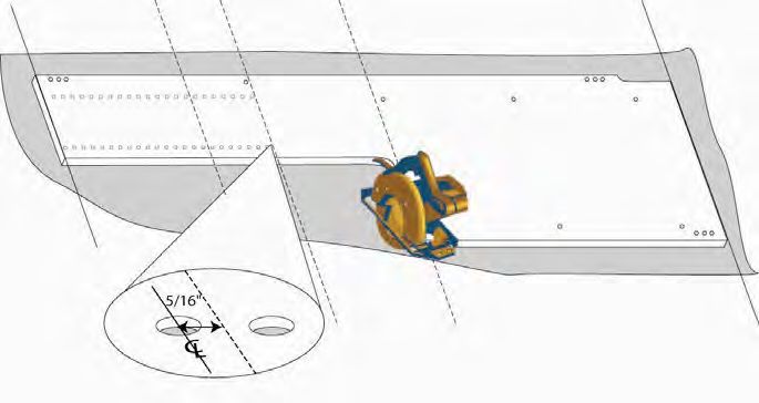
INTRODUCTION
                                                                                  Working with Different Wall Types

The key to ensuring your MasterSuite® closet is safely and adequately fastened to the walls is using the correct fasteners
for the job. Different wall types require different fasteners due to the weight and engineering of this system. The chart
below lists the various walls types commonly found in detached homes and high rise apartments, as well as the various
fasteners we recommend you use in installation of this product.

In addition to having a familiarity with various wall types, it is also necessary to be aware of potential obstacles located
within the closet walls. Your closet walls may contain plumbing pipes, ventilation ducts, pocket doors, wall safes and other
hazards. Drilling a hole or screw into any one of these obstacles can be costly and/or dangerous. We strongly urge you to
thoroughly examine the walls to which you will be fastening the closet system and/or query the homeowner, if available,
on potential hazards before you begin installation.

Fasten unit                                                  WALL TYPE
(below) to
wall type                                                                                                  Plywood
(right) using                         Drywall                                                            Particle Board
fastener                                                              Plater & Lath       Masonry            Cedar
listed in                                                                                                   WOOD OR
chart             WOOD STUD         METAL STUD         NO STUD
                                                                                                           METAL STUD

Floor                                                Easy Anchor
                  4.5x60mm          4.5x60mm                           4.5x60mm           1-1/4 in.
Mounted                                                  and                                              #8 x 1-1/4 in.
                   (2-3/8 in.)       (2-3/8 in.)                        (2-3/8 in.)       concrete
Partition                                             #8 x 1-1/4                                          wood screw
                  wood screw        wood screw                         wood screw       anchor screw
Cleat                                                   screw

                  #10 x 2 in.                                           #10 x 2 in.       1-1/4 in.
Hanging                                NOT                                                                #8 x 1-1/4 in.
                  washer hex                        Zip toggle bolt    washer hex         concrete
Track/Rail                         RECOMMENDED                                                            wood screw
                  head screw                                           head screw       anchor screw

                                                     Easy Anchor
                                   #8 x 1-1/4 in.         and                             1-1/4 in.        #8 x 5/8 in.
                 #8 x 1-1/4 in.                                       #8 x 1-1/4 in.
Pole Cup                                                                                  concrete
                 wood screw        wood screw        #8 x 1-1/4 in.   wood screw                           wood screw
                                                                                        anchor screw
                                                        screw

                                                     Easy Anchor
                                                          and                             1-1/4 in.        #8 x 5/8 in.
Shelf/Pole       #8 x 1-1/4 in.    #8 x 1-1/4 in.                     #8 x 1-1/4 in.
                                                                                          concrete
Bracket          wood screw        wood screw        #8 x 1-1/4 in.   wood screw                           wood screw
                                                                                        anchor screw
                                                        screw

Top Shelf         4.5x60mm          4.5x60mm                           4.5x60mm           1-1/4 in.
                                                         NOT                                              #8 x 1-1/4 in.
Support            (2-3/8 in.)       (2-3/8 in.)                        (2-3/8 in.)       concrete
                                                     RECOMMENDED                                          wood screw
(Corbel)          wood screw        wood screw                         wood screw       anchor screw

                                                     Easy Anchor
Plastic                                                   and                             1-1/4 in.        #8 x 5/8 in.
                 #8 x 1-1/4 in.    #8 x 1-1/4 in.                     #8 x 1-1/4 in.
Angle                                                                                     concrete
                 wood screw        wood screw        #8 x 1-1/4 in.   wood screw                           wood screw
Bracket                                                                                 anchor screw
                                                        screw

4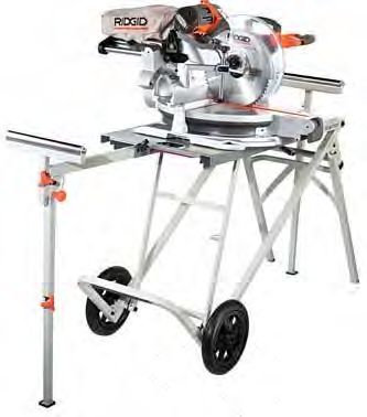
BACK PANEL ASSEMBLY
                                                                                                  Back Panels

                           PREPARATION                                       ORDER OF ASSEMBLY

Back Panel Tips:                                                             }   Back Panels

• Back panel installation requires advanced, experienced                           Shelving /Towers
  carpentry skills.                                                                Drawers and Doors
• Backs panels are only designed for floor-mount installation and                  Adjustable Shelves
  should always be used in conjunction with toe kicks or base molding.             Molding
• We’ll remind you to carefully plan the number of cuts and the                    Baskets, Valet Rods,
  number of pieces required for any given back panel design. You                   Tie & Belt Racks, and
  must consider a minor waste factor for lengths you cannot use, and               other accessories
  you must consider seaming. Measure twice and cut once.                           Islands
• The seam created between back panels should always be hidden                     Benches
  behind an upright shelf panel.

• It is essential that your saw blade is maintained in excellent
  condition to prevent or reduce chipping or ragged edges on cuts.
  Always make a test cut on scrap material first to ensure you’ll get a                  PARTS
  clean cut.
                                                                            Back Panel
• As per all MasterSuite® installation, begin installation in the highest
  and furthest point in the closet. It is best to begin in a corner.
                                                                            23-Gauge Headless Pin Nails

• Remove closet base board prior to installation.

• Installing the back panels throughout the panel installation (as
  opposed to installing ALL back panels to the wall first) will prevent
  major shifts from uneven floors.

Back Panel Cutting Guide

Nominal Shelf Width          Back Panel Width
18 in.                       18 3/4 in.
24 in.                       24 3/4 in.
30 in.                       30 3/4 in.
36 in.                       36 3/4 in.
Standard Corner              30 in. and 30 3/8 in.
Custom                       Shelf Width + 3/4 in.

Nominal Panel Height         Back Panel Height
84 in.                       85 5/8 in.
96 in.                       95 3/4 in.
Custom                       Shelf Height + 3/8 in.

Please note: The levelness of a floor may affect the necessary height
of the back panel. Always measure the space

                                                                                                           5
BACK PANEL ASSEMBLY
                                                                                                        Back Panels

                                                 INSTALLATION

1. Measure width of shelf and mark your first back panel according to the cutting guide.

2. Using a table saw with 80-teeth or 96-teeth blade, cut back panel to necessary size.

3. Position your back panel on the floor and against the wall, leaving 3/8 in. gap between back panel and wall to
   account for unsquared walls. (See FIG. 1) Add shims, if necessary, to level the back panel.

4. Secure back panel using a nail gun and 23-gauge headless pin nails. Nails should be fastened around the
   perimeter of the back panel and into studs when possible. For any width greater than 30 in., nails should be
   secured through the center of the back panel, consider the shelving design and align nails to be behind shelves
   when possible. (See FIG. 2)

5. Cut second panel to size and position next to the first panel. (See FIG. 3) Level as necessary.

6. Install first tower or corner tower as explained in the Tower Systems section.

7. Repeat measuring, cutting, and fastening steps for each additional back panel in conjunction with the Tower
   System installation. Back panels should always be installed one section further than the upright panel.

8. For exposed end configurations, installation is not complete until scribe molding is fastened to the back side
   of the exposed end(s). Installation of scribe molding should be completed after the base molding is installed
   when applicable.

9. Measure from the top of the upright panel to the floor (or to the top of the base molding). Mark length on
   scribe molding and cut to size using a miter saw.

10. Fasten scribe molding to the back side of the exposed end(s) by inserting nails with a nail gun every 12 in.
    between the top to bottom of the upright panel.

FIG. 1                        FIG. 2                                    FIG. 3

6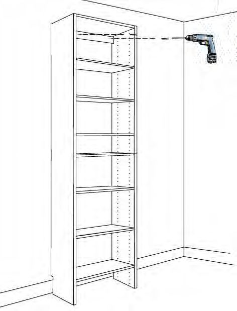
SHELVING/TOWER ASSEMBLY
                                                                                                    Stand Alone Tower

                              PREPARATION                                           ORDER OF ASSEMBLY

Screw-In Studs or Double-Sided Studs?                                                     Back Panels

Use screw-in studs only in partitions positioned on the end or in
                                                                                    }   Shelving /Towers
corners. For stand-alone towers, screw-in-studs will typically be used.                   Drawers and Doors
Thread screw-in studs into partition holes until the stop ring is snug                    Adjustable Shelves
with the partition face.
                                                                                          Molding
Use double-sided studs for contiguous closet sections in which you
                                                                                          Baskets, Valet Rods,
need to have two fixed shelves fastened to either side of the same
                                                                                          Tie & Belt Racks, and
system hole. For example, you must use double-sided studs for
                                                                                          other accessories
neighboring fixed shelves of adjacent double hang sections. For Tower
System or Hanging System, a mix of screw-in studs and double-sided                        Islands
studs may be used.                                                                        Benches

                              INSTALLATION                                                      PARTS

1. Lay down both tower side panels (partitions) face up on the                     Upright Partitions
   cardboard or cloth with the notched ends at the bottom facing in.
                                                                                   Cleat/Toekick
   (See FIG. 1) Use a screwdriver to thread six (6) screw-in studs into
   each side panel. Two (2) screw-in-studs will go into top holes, two             Cam Fixed Shelves
   (2) screw-in-studs will go into holes located 43 in. down from top,             Screw in Studs or Double-Sided
   and two (2) screw-in studs will be above the baseboard notch (5th               Studs
   hole from the bottom of the panel).
                                                                                   #8 x 1-1/4 in. Screws
   NOTE: Depending upon the design, the use of screw-in-studs may be               #8 x 5/8 in. Screws
   interchangeable with double-sided studs for contiguous sections or adjacent
   towers. Use appropriate fastener for the design.                                HiLow Screws
                                                                                   Angle (Corner) Brackets
2. Align dowels in one end of cleat with holes in top of left panel as
   shown. Push cleat dowels into holes. (See FIG. 2)                               Easy Anchors
                                                                                   Fast Caps
   NOTE: For towers with drawers or baskets, it is optional to fasten the
   slide runners on each of the side panel either before full assembly, lying on   Assorted closet components
   the floor, or after standing up the tower. (See “Drawer” in “DRAWER AND         (adj. and fixed cam shelves, etc.)
   DOOR ASSEMBLY” section for detailed instructions on runner location and
   installation.)

3. Turn panel over onto its back edge. Use one (1) HiLow Screw
   through hole in side panel. (See FIG. 3A) Line up two of the cam
   locks of the top fixed shelf over the screw-in studs and push down
   over the cams to fasten. Tighten the joint by turning each of the
   cam locks a full 180˚ clockwise with a Phillips head screwdriver.
   (See FIG. 3B) Next, fasten the bottom fixed shelf. (See FIG. 3C)
   Finally, attach the middle fixed shelf. (See FIG. 3D)

                                                                                                                        7
SHELVING/TOWER ASSEMBLY
                                                                                                    Stand Alone Tower

    NOTE: Omit bottom shelf if appropriate to the design or for double-hang section.
    NOTE: The location of the middle shelf may vary if you plan different door or drawer combinations in this tower, or for taller
    towers, or for non-standard double-hang height sections. For best results, measure the height of the clothes to hang in the bottom
    half of the double hang to ensure they will fit.
    NOTE: It may be difficult to screw in cleats while the tower panels are lying on the floor. You may wish to complete fastening of
    cleats once you stand up the tower.

4. To use the cleat as a toekick, remove the four dowels from the cleat. Fasten the cleat in the toekick position
   using one HiLow screw through each side panel. (See FIG. 4) (See “Toe Kick Installation” instructions for
   further details on contiguous panel toekick installation.)

5. Attach the remaining side panel to the cammed shelves and cleats or toe kicks following steps 3-5, as
   necessary. (See FIG. 5) If preferred, gently rollover the tower onto either side panel in order to complete
   fastening of various screws and studs into each panel.

6. Stand up the tower. Add fast caps to any exposed screw heads. Place the tower in its final location in the
   closet. Watch for overhead obstacles while maneuvering tower into place.

7. Level tower system, adding shims, if necessary, to one or more partitions.

8. Attach fast caps to any exposed screw heads.

    •   Fasten the tower to the closet’s wall with appropriate wall screws through the upper cleat. (See “Working
        with Different Wall Types” for details.) (See FIG. 6)

9. After securing all parts and tightening cleat screws, install the remaining accessories (doors, drawers, shoe
   fences, sliding racks, etc.).

8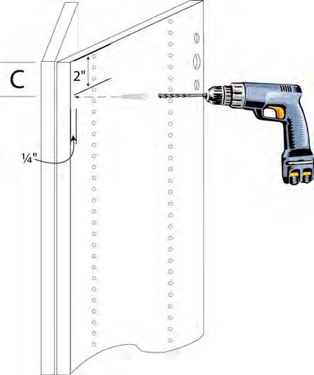
SHELVING/TOWER ASSEMBLY
                                                                 Stand Alone Tower

    43”

FIG. 1                                       FIG. 2

             b

         a

                     d

                 c

FIG. 3                                       FIG. 4

                         a
                                     d

                             c

                                         d

                                 b

FIG. 5                                       FIG. 6
                                                                                 9
SHELVING/TOWER ASSEMBLY
                                                                                                   Tower System

                              PREPARATION                                             ORDER OF ASSEMBLY

Screw-In Studs or Double-Sided Studs?                                                       Back Panels

Use screw-in studs only in partitions positioned on the end or in
                                                                                      }   Shelving /Towers
corners. For stand-alone towers, screw-in-studs will typically be                           Drawers and Doors
used. Thread screw-in studs into partition holes until the stop ring is                     Adjustable Shelves
snug with the partition face.
                                                                                            Molding
Use double-sided studs for contiguous closet sections in which
                                                                                            Baskets, Valet Rods,
you need to have two fixed shelves fastened to either side of the
                                                                                            Tie & Belt Racks, and
same system hole. For example, you must use double-sided studs
                                                                                            other accessories
for neighboring fixed shelves of adjacent double hang sections.
For Tower System or Hanging System, a mix of screw-in studs and                             Islands
double-sided studs may be used.                                                             Benches

                              INSTALLATION                                                        PARTS

                                                                                     85-5/8 in. Partitions (or other
1. Lay down both tower side panels (partitions) face up on the
                                                                                     length partitions)
   cardboard or cloth with the notched ends at the bot-tom facing
   in. (See Fig. 1.) Use a screw-driver to thread six (6) screw-in                   Cleat/Toekick
   studs into one side panel (the one that will be on the side wall)                 Cam Fixed Shelves
   as shown. Two (2) screw-in studs will go into top holes, two (2)
   screw-in studs will go into holes located 43 in. down from top,                   Screw-in Studs (#56544) or
   and two (2) screw-in studs will be above the baseboard notch                      Double-Sided Studs (#56534)
   (5th from the bottom of the panel). (Do not install studs into the                #8 x 1-1/4 in. Screws
   other panel at this time!)                                                        #8 x 5/8 in. Screws

     NOTE: For towers with drawers or baskets, it is optional to fasten the          HiLow Screws
     slide runners on each of the side panels either before full assembly or after   Angle (Corner) Brackets
     standing up the tower. (See “Drawer” in “DRAWER AND DOOR ASSEMBLY”
     section for detailed instructions on runner location and installation.)         Easy Anchors
     •   Align dowels in one end of cleat with holes in top of left panel            Fast Caps
         as shown. Push cleat dowels into holes.                                     Assorted closet components
         (See FIG. 2)                                                                (adj. and fixed cam shelves, etc.)
     •   Turn panel over and thread one (1) HiLow screw from hole in
         outside of left panel into center hole of cleat. (See FIG. 3)

     •   Stand panel/cleat upright and place into position in closet
         as shown in FIG. 4. Secure panel to one sidewall using
         appropriate wall hardware (see “Working with Different
         Wall Types”). Secure wall hardware at top and bottom of
         panel (at about the 7th or 8th hole locations) preferably at a
         stud location.

10
SHELVING/TOWER ASSEMBLY
Tower System
• Position the next panel (a thru-drilled panel for a continuous system), aligning the holes in the panel with
the dowels in the cleat. Thread one (1) HiLow screw from hole in outside of thru-drilled panel into center
hole of cleat. (See FIG. 5a) Push double-sided studs through holes in panel to align with previously-
installed screw-in studs. (See FIG. 5b)
• Fasten the cleat to the closet’s wall with two appropriate wall screws. (See ‘Working with Different
Wall Types’ section and FIG. 6)
HINT: In the case of walls which are not square, do not fully tighten cleat screws until all system parts are in place!
• Line up two of the cam locks of the top fixed shelf over the screw-in/double-sided studs and press over the
cams to fasten. Tighten the joint by turning each of the cam locks a full 180˚ clockwise with a Phillips head
screwdriver. (See FIG. 7)
• Next, fasten the bottom fixed shelf by angling the shelf upwards and pushing the back cams over the studs
in the back. (See FIG. 7b) Use a screwdriver to turn each cam lock a full 180˚ clockwise. (See FIG. 7a and
FIG 7b) Lower front of shelf and use a short-handled screwdriver to secure front cam locks. (See FIG. 8)
NOTE: Omit bottom shelf if appropriate to the design or for double-hang section.
2. Attach another cleat as shown in FIG. 9. (Note: Each successive cleat will only have one HiLow Screw
attached through each successive panel.)
• Attach another panel (thru-drilled or stop drilled) to the cleat. Secure cleat through second panel with one
(1) HiLow Screw. (See FIG. 10)
3. Continue to build the tower system across the wall by repeating steps 6-10 to secure all parts of
the system.
4. Add middle shelf(ves), as detailed in step 7 to tighten the cams.
NOTE: The location of the middle shelf may vary if you plan different door or drawer combinations in this tower, or for taller
towers, or for non-standard double-hang height sections. For best results, measure the height of the clothes to hang in the bottom
half of the double hang to ensure they will fit.
5. Level tower system, adding shims, if necessary, to one or more partitions.
6. Attach toekicks, if appropriate, by removing dowels from cleats and securing to front of panel with one (1)
HiLow Screw. (See “Toe Kick Installation” instructions for further details on contiguous panel
toekick installation.)
7. Attach fast caps to any exposed screw heads.
8. After securing all parts and tightening cleat screws, install the remaining accessories (doors, drawers, shoe
fences, sliding racks, etc.).
11SHELVING/TOWER ASSEMBLY
Tower System
43”
FIG. 1 FIG. 2
FIG. 3 FIG. 4
12
12SHELVING/TOWER ASSEMBLY
Tower System
a
b
FIG. 5 FIG. 6
a
b
FIG. 7 FIG. 8
FIG. 9 FIG. 10
13SHELVING/TOWER ASSEMBLY
Hanging Tower System
PREPARATION ORDER OF ASSEMBLY
Installation of a MasterSuite Hanging System and related sections Back Panels
requires skill and familiarity with the installation of the floor- } Shelving /Towers
mounted shelf tower and its related components.
Drawers and Doors
The rail-mounted hanging closet system relies upon correct
Adjustable Shelves
anchoring of the rail to the wall supports, proper cleat assembly, and
mounting of the brackets to the partitions to bear the considerable Molding
weight of the system. Accurate fastening of these components is Baskets, Valet Rods,
essential to ensuring the system is safely and permanently secured. Tie & Belt Racks, and
We also recommend that any panel that is adjacent to a side wall be other accessories
secured to that side wall at a stud location.
Islands
• Ensure the hanging vertical partitions do not require trimming Benches
to fit above the closet’s baseboard. Ensure the closet height is
sufficient to accommodate use of your screw gun to install the
top shelf if the design uses a continuous top shelf piece. You may
need to shorten, or notch the partitions to fit above, or around,
the baseboard. PARTS
• Mount all left and right suspension brackets to the hanging Rail and Cover
partitions prior to system installation using two (2) #8 x 5/8 in.
Cleat (for each “center” tower)
screws through the bracket into the pre-drilled bracket holes
on the partition. Snap on Fast Caps to the opposite side of the #10 x 2 in. Washer Hex Head
partition over the exposed bracket holes. (See FIG. 1) Screws
• Mount all drawer and basket runners, if desired, prior to hanging Left and Right Brackets
partitions on the rail. (See “Drawer” or “Basket” assembly Fast Caps
sections for instructions regarding runner installation.)
Hanging Partitions (any length
with at least one 80 in. or 60 in.
INSTALLATION thru-drilled panel)
Cam Fixed Shelves
1. Draw a level line across the entire wall at 82-7/8 in. or 93 in. Screw-in Studs (#56544)
from the floor.
Double-Sided Studs (#56534)
2. Locate and mark the wall studs along your line. (See FIG. 2) Zip Toggle Bolts
#8 x 1-1/4 in. Screws
3. Measure from a corner of the closet wall to the center of the
first stud. Next, measure the same distance (e.g. 8-1/2 in.) from #8 x 5/8 in. Screws
the end of the rail. If the measured distance does not fall exactly Angle (Corner) Brackets
on a rail hole (See FIG. 3), you must trim the end of the rail the
length necessary to ensure the holes align with the wall studs. Easy Anchors
(Holes are pre-drilled on 1 in. centers along the length of the rail.
Studs should fall on 16 in. or 24 in. centers.) Use a hacksaw and
file to cut and de-burr a length of rail as necessary.
14SHELVING/TOWER ASSEMBLY
Hanging Tower System
4. Fasten the rail to the wall with a Zip Toggle Bolt wherever a partition will be hung that is more than 4 in. to the
left or right from the center of a stud. (See FIG. 4)
5. Positioning the bottom of the rail flush to the drawn line, fasten the rail to every stud using one #10 x 2 in.
Washer Hex Head Screw per stud. (Use Tapcons for concrete and cinder block walls. Use Zip Toggle Bolts for
stud-less walls.) THE RAIL MUST BE ANCHORED A MINIMUM OF EVERY 16 in. ALONG ITS LENGTH AND
NO MORE THAN 4 in. FROM ANCHOR TO PARTITION.
6. Trim the plastic rail cover to fit, and snap it over the length of the rail.
NOTE: If rail is to be longer than 8 feet, seam the rail cover directly behind a partition to ensure a smooth visible surface.
7. Hang the vertical partitions in their final positions from the suspension brackets on the rail. Secure any
partitions that are adjacent to a side-wall through a stud. (See “Working with Different Wall Types” for
appropriate wall hardware.)
8. Fasten all screw-in or double-sided studs into the system holes for the fixed shelves. (See FIG. 5) Thread
screw-in studs into partition holes until the stop ring is snug with the partition face. (See “Drawer” in “Drawer
and Door Assembly” section for locations of fixed shelves above, below and between banks of drawers.)
NOTE: Use screw-in studs only in partitions positioned on the end or in corners. Use double sided studs for contiguous closet
sections in which you need to have two fixed shelves fastened to either side of the same system hole. For example, you must use
double-sided studs for neighboring fixed shelves of adjacent double hang sections.
9. Working from one corner across the wall (left or right), seat the fixed shelves’ cam locks, for the end section
only (See FIG. 5a) over the screw-in studs’ heads and tighten each cam lock clockwise with a Phillips head
screw-driver until secure.
10. After fastening all fixed shelves in the end section, measure the length of the fixed shelf (e.g. 24 in.) between
the top of the corner partition and the adjacent partition. (See FIG. 5b) If necessary, tap the adjacent
partition along the top with your hand to adjust its position on the rail to meet this measurement.
• We strongly recommend that you secure a cleat to the center tower of every three (3) towers. To do so,
push dowel cleats into holes in left and right center partitions and secure cleat to each panel using a HiLow
screw. (See FIG. 5c) Secure cleat to back wall with two (2) wall screws (see “Working with Different
Wall Types”).
11. Level both end section partitions using a 4 foot level.
NOTE: Corner walls may not be level in comparison to the end partition.) Adjust partition plumbness (level) using the set screw on
the bottom of each suspension bracket. (See Fig. 6)
12. Repeats steps 9-12 for each section working to the left or right along the wall.
13. If the design uses a continuous top shelf (instead of cammed top shelving), after leveling the sections,
measure, cut and position the long, top shelf. (NOTE: This step is the one exception to the “Order of Assembly.”
For floor-mounted laminate systems, the continuous top shelf occurs after installation of all doors, drawers
and angled wall towers. See “Top Shelf and Pole” in “Shelving/Tower Assembly” section for details regarding
top shelf installation.)
15SHELVING/TOWER ASSEMBLY
Hanging Tower System
14. Before securing a continuous top shelf to each partition, adjust the distance of the partitions from the back
wall by tightening or loosening the Distance Screws. (See FIG. 6) (This step ensures the partition front edges
are positioned flush with the front edge of the top shelf.)
NOTE: The end screw adjusts the bracket/partition’s closeness to the wall (accommodating concave or convex drywall shapes),
and the bottom screw adjusts the bracket/partition’s plumbness to the wall, tilting the partition to or from plumb.
15. After making any final adjustments to the brackets’/partitions’ distance, fasten the top shelf to the top of each
partition using two (2) #8 x 1-1/4 in. screws.
16. Secure each vertical partition by fastening an angle (corner) bracket under each partition using #8 x 1-1/4 in.
screws through the bracket into an Easy Anchor in the wall (or, w/o Easy Anchor, into the stud). Then, fasten
a #8 x 5/8 in. screw from underneath through the Easy Anchor into the partition bottom using a 90-degree
angle drill. (See FIG. 7)
17. After securing all partitions with corner brackets, install the remaining accessories (doors, drawers, shoe
fences, sliding racks, etc.).
NOTE: This step may be completed in your NOTE: Marked stud
shop or on site. locations will be masked by
NOTE: Cleat holes are pre-drilled on 60 in. system components during
and 80 in. panels. Cleat holes are not pre- installation.
drilled on 48 in. panels.
NOTE: Part # 773100 #8 x 5/8 screw
FIG. 1 FIG. 2
16SHELVING/TOWER ASSEMBLY
Hanging Tower System
NOTE: For purposes of illustration, rail cover is not shown in Figs. 3 and 4.
FIG. 3 FIG. 4
b
Rai l
c
S S
ATTACH CLEAT
Cam Fixed Shelf TO CENTER
SECTION!
a
S D S
Cam Fixed Shelf Cam Fixed Shelf
S D S
Cam Fixed Shelf Cam Fixed Shelf
Screw-In Studs
S Screw In Studs
Double Sided Studs
D Double Sided Studs
FIG. 5
FIG. 6 FIG. 7
17SHELVING/TOWER ASSEMBLY
Corner Tower
PREPARATION ORDER OF ASSEMBLY
These instructions apply to corner towers using shelves or hanging. Back Panels
Please note that corner towers using the radius hanging bar should be } Shelving /Towers
matched with the large radius fixed cam corner shelves. The regular
cam and adjustable corner shelves do not match the radius curve of Drawers and Doors
the hanging bar. Further, use of either radius fixed corner shelf at the Adjustable Shelves
top of the tower will not match with the continuous top shelf material,
Molding
so it is not recommended to use a cammed top shelf IF you will also be
installing continuous top shelf material. Baskets, Valet Rods,
Tie & Belt Racks, and
• In most cases, corner towers should be assembled and installed other accessories
in the closet before installing other towers and hanging sections
Islands
along the walls.
Benches
• When one or more corner towers have been installed, you may
continue regular installation of adjoining hanging and shelving
sections.
• You may not install corner towers using the rail hanging
PARTS
MasterSuite system.
• We recommend cutting one (or more) 30 in. cleat(s) to support QTY DESCRIPTION
and square one side of the corner tower section. Prior to assembly, 2 Corner Cam Fixed
cut a 30 in. shelf tower cleat to 29-3/8 in. wide and drill out dowel
4 Shelves
(8mm) and HiLow Screw (4 mm) holes.
(See FIG. 1) 3 Corner Adjustable
Shelves (optional)
INSTALLATION 1 Vertical Partitions
(Floor Mounted
1. Lay the side panels down on the floor and fasten two of them 2 System only)
together with your trimmed 29-3/8 in. cleat and two (2) corner
30 in. Cleat
shelves, creating a 30-5/8 in. wide tower. Secure cleat with one 24
HiLow Screw through each side panel. Stand the tower up and 4.5 x 60 mm (2-3/8 in.)
place it in the corner. (See FIG. 2) screws with cover
16 caps
NOTE: Always position the partition cut-out in L-shaped shelf on the
right side, as shown in the illustration. Do NOT position fixed shelves Safety Shelf Pins (6 per
closer than 28 in. from one another. adjustable corner shelf)
HiLow Screws
2. Add the third partition panel to the open end, (FIG. 3) and fasten
it to the shelves by tightening all the cam locks in place. Screw-In and/or
Double-Sided Studs
3. Plumb and level the tower. Add shims, if necessary. Screw the (as needed) Assorted
leveled corner tower to the wall studs using 2- 3/8 in. screws closet components
with cover caps through each of the cleats, as well as through the
partition installed flush to the wall. Ensure the tower is adequately
secured to corner wall studs or nearest studs thereto.
18SHELVING/TOWER ASSEMBLY
Corner Tower
4. Add adjustable shelves (6 shelf pins per shelf) or hanging 30Ó
bars as desired. (See “Top Shelf and Pole” in “Shelving/ 29-3/8Ó
Tower Assembly” section for additional instructions.)
• Continue with installation of other towers. You may
not install corner towers using the rail hanging
MasterSuite system.
ge
Ed
ed
ish
• We recommend cutting one (or more) 30 in. cleat(s) to
in
nf
support and square one side of the corner tower section.
U
Prior to assembly, cut a 30 in. shelf tower cleat to 29-3/8 2.13Ó
.87Ó/22mm
in. wide and drill out dowel (8mm) and HiLow Screw (4 54mm
mm) holes. (See FIG. 1) 8mm
3.39Ó
86mm 4mm
Finished Edges
FIG. 1
TRIM EACH 30 in. CLEAT TO 29-3/8 in.. THEN, DRILL
HOLES FOR TWO (2) DOWELS AND ONE HOLE FOR
ONE (1) HI-LOW SCREW
Screws
Cleat
Adjustable
shelf
NOTE: For purposes of
illustration, Fig. 3 does
not show option of
cammed fixed top shelf
or hanging.
Not less
than 28"
Cut out
on right
side
FIG. 2 FIG. 3
19SHELVING/TOWER ASSEMBLY
Angled Wall Tower
PREPARATION ORDER OF ASSEMBLY
If your closet has one or more angled walls, the angled wall is likely Back Panels
positioned at a 45˚ angle to the adjacent “square” wall(s), creating } Shelving /Towers
a 135˚ angle instead of the standard 90˚ perpendicular wall. These
instructions provide assistance in the installation of adjacent towers Drawers and Doors
on these angled walls. If the angled wall is greater or less than 135˚ Adjustable Shelves
to the square wall, similar steps can be taken for installation, with
Molding
minor adjustments for the different angles. See second half of these
instructions. Baskets, Valet Rods,
Tie & Belt Racks, and
These instructions do not apply to rail-hung shelf towers. We do not other accessories
recommend attempting to connect nearly seamless, continuous top Islands
shelving on angled walls with hanging towers.
Benches
Install all the other shelving towers and hanging sections on “square”
walls first. Then begin positioning partitions for towers on adjacent
angled walls. Before cutting final pole, shelf and cleat lengths for
systems on walls adjacent to angled walls, ensure you fully PARTS
understand the positioning, measuring and cutting order to
complete this installation. QTY DESCRIPTION
4 #8 x 1-1/4 in. Wood
Screw (for every 2
partitions on angle)
INSTALLATION
4 4.5 x 60 mm (2-3/8
45˚ ANGLE WALL in.) Screw (for every 2
partitions on angle
1. Cut the 135˚ angle “wedge” to support the first partition on the
angled wall. Using scrap 14 in. top shelving or other material, 4 Angle (Corner) Bracket
measure 14 in. along the long edge to “A”. Mark a line across the Assorted closet
shelf using a square, making a square box (Fig. 1A). Next draw a components
diagonal line bisecting the 14 in. square from corner to corner.
Measure and mark 14 in. from the board corner along the diagonal
at “B”. Draw a line connecting “B” to corner “C”.
(FIG. 1C)
2. Cut the 135˚ triangle wedge from the board. (See FIG. 1)
3. Repeat steps 1 and 2 to create a second wedge. You need two (2)
triangles for each angled corner to fit between two (2) adjacent
angled partitions.
4. Secure one wedge to the upper portion of the partition 14 in.
down from the top and one to the lower portion of the partition
(14 in. from the bottom). Fasten each wedge to the partition
20SHELVING/TOWER ASSEMBLY
Angled Wall Tower
with the panel lying on the floor, using one (1) #8 x 1-1/4 in. wood screw through a front system hole into the
wedge edge and one (2) 4.5 x 60 mm (2-3/8 in.) Screw through the back system hole. (See Fig. 3) (As fast
caps will not fit over these screws and the system holes, we recommend countersinking these screws into the
system holes.) (See over-head view, FIG. 2)
5. Flip the assembled partition over on the floor and attach the second partition to the opposite side as in step 4.
(See FIG. 4)
6. Stand up the assembled unit and position it in its final location on the angled wall corner. Level the unit and
secure it to the two walls, fastening two (2) angle (corner) brackets on each partition near the wedge supports.
OTHER ANGLED WALLS
7. If the adjacent angled wall is not at a standard 45˚ angle to the square wall, you must toenail together the
adjacent angled partitions. Additionally, please note that if the wall angle on one side turns out to be much
wider, conversely, the angle on the other side of the tower connecting with the next wall will be that much
smaller. Do not assume the angles on both sides of the tower will be the
same size!
8. Using two (2) adjustable shelves as squares for the partitions, place the rear, unfinished long edges
horizontally against the two walls or baseboards.
9. Place the two partitions (which will meet along their front edges) up against the walls vertically and push
them together with the shelves until the inside front edges meet. (See FIG. 5) (If the design indicates
two adjacent shelf towers at this intersection, you may simply slide the assembled towers together on the
adjacent angled walls until the front edges meet.)
10. Standing on a step ladder, counterbore straight through the vertical partition (at the top of one partition
1/4 in. from the front edge and 2 in. down from the top of the partition.) (See FIG. 6C)
11. Holding the two partitions together tightly, screw in one (1) #8 x 1-1/4 in. wood screw through the pre-drilled
hole and into the second partition. (See FIG. 6)
12. Having secured the partitions at the top, move down on the partition and repeat steps 10 and 11, secure the
two partitions together at the mid-height and at the bottom of the partition with the wood screws.
INSTALLING CONTINUOUS TOP SHELF
13. After assembling and installing all towers, begin measuring for the continuous top shelf.(Cammed top shelves
may not be used between angled wall partitions.)
14. Measure along the square back wall to the corner of the angled wall. (Measurement of FIG. 7D) Then
measure in front of the towers to the corner where the partitions’ front edges meet. (Measurement of
FIG. 7E). Mark these measurements along the respective front and back edges of the top shelf material.
15. Repeat step 14 measuring all walls in front and in back of each tower to establish the angles at which
to cut each top shelf.
21SHELVING/TOWER ASSEMBLY
Angled Wall Tower
16. Draw a cutting line between the two measurements on
each top shelf. Cut each top shelf as measured (fitting
each piece as you go to ensure a tight fit), and attach the
top shelf to the partitions using #8 x 1-1/4 in. screws.
(See “Top Shelf and Pole” in “Shelving/Tower
Assembly” section for further details.)
FIG. 1
FIG. 2 FIG. 3 FIG. 4
FIG. 5 FIG. 6 FIG. 7
22SHELVING/TOWER ASSEMBLY
Single & Double-Wide Hutch
PREPARATION ORDER OF ASSEMBLY
Hutch towers may be installed in a variety of configurations, from Back Panels
stand alone to multiple, contiguous, side-by-side units, potentially } Shelving /Towers
sharing section-dividing vertical panels. Additionally, there are many
potential combinations of doors, drawers and other accessories for Drawers and Doors
both the top and bottom sections. Adjustable Shelves
Each hutch tower is comprised of a minimum of: a set of vertical Molding
panels, 3 fixed hutch shelves, and 3 cleats. Hardware is sold Baskets, Valet Rods,
separately. A hutch tower may also be complemented with one or Tie & Belt Racks, and
more doors, drawers, hampers, or baskets. other accessories
See “Drawer” in “Drawer and Door Assembly” section for Islands
instructions on assembly of each drawer box. However, for installing
Benches
drawer slides, please note that the front hole will
align-with system hole, but back hole will need to be drilled. Use
appropriate slide template and drill with 5mm self-centering bit. Also,
note new 18 in. deep drawer box, available in 24 in. or 30 in. width.
PARTS
See “Hamper Door”, “Tower Door” (in “Drawer and Door
Assembly”), “Basket” (in “Accessory Assembly”), and “Toe QTY DESCRIPTION
Kick” (in “Shelving/Tower Assembly”) for specific installation
instructions on those items. 1+ Panel Pack (2
Vertical panels
3+ Cammed Fixed Hutch
INSTALLATION Shelves
1 Standard 14 in. Shelf
SINGLE HUTCH (for top section)
3 Cleats
1. Prior to assembling a hutch unit, ensure the unit will fit over
any existing baseboard trim.(Notch clearance is 5-5/8 in. high OPTIONAL DEPENDING
by 1-1/16 in. deep.) If vertical panels will not fit over existing ON DESIGN:
baseboard, trim to fit before proceeding with assembly. Double-sided Studs (for
double-wide unit)
2. Place one vertical panel on a protective surface on the floor with
Top Shelf (for double-
its inside facing up. (See FIG. 1A)
wide unit)
NOTE: Use a blanket or other cloth underneath panels if you are working on a Edgebanding Tape
hardwood or tiled floor to prevent scratches on the melamine surface.
Hamper Door and
3. Insert 2 screw-in studs (or double-sided studs, if appropriate Basket
for design) for each fixed shelf (FIG. 1A) into the appropriate, Cabinet Doors
corresponding holes in the first vertical panel. Baskets
4. Fit the shelves over the screw-in studs. (FIG. 1C) Fit the cleats/ Hutch Jewelry Drawer
toekick (FIG. D) into appropriate dowel holes and press until snug Insert
with the first vertical panel. Tighten the cams.
23SHELVING/TOWER ASSEMBLY
Single & Double-Wide Hutch
NOTE: If you are installing an adjacent hutch, see “Toe Kick” in “Shelving/Tower Assembly” section for instructions on side-by-side
toe kick assembly.
5. Insert the screw-in studs (or double-sided studs) for each fixed shelf into the second vertical panel.
(See FIG. 1E)
6. Lay the second vertical panel with the screw-in studs over the exposed cleat dowels and press together gently,
fitting the cam locks over the screw-in studs carefully, until all pieces fit snugly. Tighten the cam locks.
(See FIG. 1F)
7. Insert and fasten the HiLow screw into each hole provided for the cleats/toekick on one vertical panel. (See
FIG. 1G) Add fast caps over all fastened HiLow screws. Gently roll the “box” over onto its back and repeat the
fastening of screws and fast caps on the other partition.
8. If you have upgrades or accessories you prefer to attach to the unit prior to standing it up, we recommend
you fasten drawer or basket runners now, or door hinges. (See appropriate upgrade or accessory assembly
instructions for details.)
9. Stand up the hutch tower. Place the hutch in its final position in the closet. (This step may require the
assistance of a second installer to maneuver the hutch under a soffit and/or around sliding doors in the closet.)
DOUBLE WIDE HUTCH
Double wide hutch towers may be assembled contiguously, separated and supported by a single, vertical panel positioned
between towers, or the separating vertical panel can be trimmed so that the hutch “counter” piece is continuous across
two or more tower cabinets. (as shown at right in FIG. 2)
Since this is not a standard hutch configuration, it is necessary to modify existing materials to create an extra-wide unit.
Exactly how much material you trim to fit this custom design depends upon the desired configuration. For example, your
client may desire only two (2) shelves spaced 10 in. apart below the top shelf. Thus, you would need to trim a thru-drilled
middle vertical panel’s top shelving section to create a shelving section. Or, for an 8-foot tall hutch with doors on the upper
section, this middle vertical panel would need to be trimmed to match the door height of 36-1/2 in..
Additionally, you must ensure this custom trimmed middle panel is cut to align with the system 32 hole pattern for top
and bottom fixed shelves. See close up for FIG. 3 for details.
1. Prepare one or more separating middle vertical panels 3/8 in. using a thru-drilled panel. First, trim to fit the
upper Fig. 3 portion of your vertical panel to match your design plus 3/8 in. below the center of the nearest
system hole; for shelves or doors (24 in. or 36 in. – 8 foot unit only). For,example, for 24 in. hutch doors,
measure down from the top of the vertical panel, plus 3/8 in. below the center of the nearest system hole and
mark your cut line. (See FIG. 3)
For other top section sizes, measure the appropriate distance, adding 3/8 in. from the center of the bottom
system hole.
2. Cut the vertical panel to the dimensions you’ve marked.
3. Edgeband the visible bottom edge of this upper vertical panel.
24SHELVING/TOWER ASSEMBLY
Single & Double-Wide Hutch
4. Mark and trim the bottom of the middle vertical panel from the bottom end of the panel, plus 3/8 in. above the
PARTS
center of the nearest system hole. Discard the trimmed middle section of the original panel.
5. Through-drill all assembly holes on these top and bottom panel pieces. (If you are fastening drawer runners or
basket slides on either side of this panel, you must thru-drill all holes for mounting runners as well.)
6. Assemble double-wide hutch tower in its final location, following the basic steps in the single hutch assembly
above, using the pieces shown at right. This may require a second installer. (See FIG. 4)
7. Install the second toe kick per “Toe Kick” instructions in “Shelving/Tower Assembly” section once the double-
wide tower is in its final location.
8. To install double-wide hutch upper section, work from the left to the right. Secure the first upper cleat to the
left vertical panel. Next, remove a dowel from the other side of the cleat (bottom dowel is removed in FIG. 5).
Hang the middle upper panel from this cleat using one (1) HiLow screw countersunk through the middle panel
into the left cleat. (See FIG. 5)
9. Remove the opposite dowel from the second upper cleat (upper dowel is removed in FIG. 5). Install the
second upper cleat into the middle vertical panel (FIG. 5) with one (1) HiLow screw from the right vertical
panel into the right cleat.
10. Fasten all remaining cleats, toekicks and fixed shelves to
outside left and right panels snugly.
11. If you have upgrades or accessories with drawer or
basket runners, or door hinges, fasten the runners
and/or hinges. (See appropriate upgrade or accessory
assembly instructions for details.)
12. Level the hutch tower(s). If necessary add shims
underneath one or more vertical panel(s).
13. Assemble and install the upgrades and/or accessories
(drawers, doors, hampers) in the hutch. Re-level the
hutch tower, if necessary.
14. Fasten the hutch to the closet’s wall with the
appropriate screws through the top cleat. (FIG. 3) (See
“Working with Different Wall Types” in Installation
Manual for details.)
15. Install the adjustable shelves using safety shelf pins.
* Hutch drawings may vary slightly
from actual product.
25SHELVING/TOWER ASSEMBLY
Single & Double-Wide Hutch
FIG. 1 FIG. 2
FIG. 3
Cleat
H i-Low
Screw
FIG. 5 FIG. 4
26SHELVING/TOWER ASSEMBLY
Toe Kick
PREPARATION ORDER OF ASSEMBLY
Plan ahead when assembling adjoining shelf towers. If you put Back Panels
together all the partitions and fixed shelves of two side-by- side } Shelving /Towers
towers before you’ve installed the second toe kick, you’ve got no
access to fasten the inside panel. To install adjacent toe kicks, follow Drawers and Doors
these steps: Adjustable Shelves
Molding
INSTALLATION
Baskets, Valet Rods,
Tie & Belt Racks, and
1. Assemble the first tower, using HiLow screws to attach the toe other accessories
kick. (If you have multiple tower toe kicks to install next to one
another, you must countersink all the adjacent HiLow screws for Islands
the pieces to fit snugly.) Benches
2. Fasten the second tower’s bottom fixed shelf using only the back
cam locks over the double-sided studs (#56534), and tilt the shelf
up vertically (like a hinged lid). (See FIG. 1A below)
PARTS
3. Now fasten the second toe kick to the outside partition using one
(1) HiLow screw. (FIG. 1C) Use two plastic angle brackets to fasten QTY DESCRIPTION
the toe kick to the “center” (shared) partition. (See FIG. 1B) 1+ Toe Kick
4. Lastly, lower the fastened bottom cammed fixed shelf to sit on the
4+ HiLow Screws (#2308)
toe kick. Be sure to add fast caps to exposed HiLow screw heads. 4+ Double Sided Studs
2+ Angle Brackets
NOTE: With the toe kick supporting the weight of the front of the
bottom fixed shelf, it is not necessary to install the front screw-in
or double-sided studs for the cam locks.
FIG. 1
27DOOR & DRAWER ASSEMBLY
Drawer
PREPARATION ORDER OF ASSEMBLY
• Whenever possible for greatest leverage, mount drawer runners Back Panels
to the side panels (partitions) while panels are lying on the floor Shelving /Towers
(before side panels are mounted in the closet).
} Drawers and Doors
• Similar to basket installation, drawers re-quire mounting one fixed Adjustable Shelves
shelf above and one below the rack of drawers for stability.
Molding
• Drawers (and baskets) should never be mounted behind
Baskets, Valet Rods,
overlapping sliding doors or in locations where an open drawer
Tie & Belt Racks, and
may bump into another obstacle.
other accessories
Islands
INSTALLATION
Benches
1. Attach drawer sides to drawer back with four (4) #8 x 1-1/4 in.
Phillips Head Screws. (See FIG. 1)
2. Insert the drawer bottom into the slot along the bottom of the PARTS
drawer sides. (See FIG. 2) Push the cam locks into the holes in the
drawer sides. Be sure to orient cams so that the open end of the QTY DESCRIPTION
cam faces the hole in the front edge.
1 Drawer (face, bottom,
3. Locate your selected drawer front(s). Choose your handle size and back and side panels)
drill a 1/16 in. pilot hole through each corresponding dimple on 2 Drawer Runners (left
the back of the drawer front. Turn the drawer front over and drill a and right)
3/16 in. hole for handle at pilot location(s).
2 or 4 Cam locks
NOTE: It is important to drill both the pilot hole through the back (6 in. H = 2; 10 in. H = 4)
and the regular hole through the front to prevent chipping. 2 or 4 Screw-in Studs
(6 in. H = 2; 10 in. H = 4)
4. Attach the drawer handle. (Three sizes of screws are supplied to
accommodate drawer front styles.) (See FIG. 3)
2 or 6 #6 x 1/2 in. Screws (for
14 in. or 18 in. deep
5. Thread 2 (or 4 for 10 in. drawer) screw-in studs to drawer drawers)
front. Attach drawer front to drawer assembly. Use a Phillips
4 Euro Screws
screwdriver to tighten cam locks.
1 Drawer Handle
For 14 in. D drawers, use two #6 x 1/2 in. wood screws to attach (with included
each drawer runner to a drawer side. handle hardware)
4 #8 x 1-1/4Ó Phillips
For 18 in. D drawers, use three #6 x 1/2 in. wood screws.
Head Screws
6. Place 14 in. or 18 in. Slide template into partition holes (so arrow 1 14 in. or 18 in. Slide
points forward) at desired drawer runner location. Use a 5mm Template (#05-90052
Self-Centering Drill Bit to drill holes as marked in template. Attach or #05-90053)
each drawer runner to partition with two (2) Euro screws.
28DOOR & DRAWER ASSEMBLY
Drawer
7. Use the charts below for standard drawer, basket and hamper door combinations (“A” through “J”). Start by
PARTS
placing the first set of drawer runners in the first hole above the bottom fixed shelf. (FIG. 4) Then, count
holes again for each additional drawer or basket as shown in the chart below. (See Basket Assembly for
basket hole spacing.)
8. If drawer faces do not align properly, use shims and a level to raise or lower, as appropriate, the
relating partitions.
9. You must install one fixed shelf after every three (3) drawers (as in combo C). For combinations B, E, F,
H, I and J, install the middle fixed shelf below the second drawer. (Middle fixed shelves mount to the holes
directly below the immediate drawer runner above.)
CAM LOCKS
FIG. 1 FIG. 2
1 2 8 mm
9 6 mm
FIG. 3 FIG. 4
29DOOR & DRAWER ASSEMBLY
Drawer
A B C D E F G H I J
SPACING GUIDE FOR 42 in. H SECTION
SPACING (COUNT EVERY X HOLES) SPACING (COUNT EVERY X HOLES)
DRAWER DRAWER
HEIGHT HEIGHT
B C D E F G H I J
6 in. 5th 5th 5th 5th 6 in. 5th 5th 5th 5th 5th
6 in. - 5th 5th 5th 6 in. 5th - 5th - -
6 in. - 5th 5th 5th 10 in. 8th 8th - 8th 8th
6 in. - 5th 5th - 10 in. 8th 8th - - -
6 in. - - 5th - 10 in. - 8th - - -
Hamper
10 in. 8th 8th - 8th - - - - -
Door
3 in.
10 in. 8th - - - 17 in. - - - -
Down
10 in. 8th - - - - - - - - -
TOTAL 36-1/2 31-1/4 28-5/8 TOTAL 32-1/4 36-1/2 34-1/4 40-1/4
35 in. 30 in.
HEIGHT in. in. in. HEIGHT in. in. in. in.
* Total Height from center to center of top and bottom fixed shelves.
30DOOR & DRAWER ASSEMBLY
Hamper Door
INSTALLATION ORDER OF ASSEMBLY
1. (See FIG. 1) Back Panels
Shelving /Towers
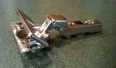
2. Insert each hinge into a set of three (3) holes on the back of the
hamper door, then turn the fastening screw one quarter turn } Drawers and Doors
clockwise (as shown with arrows on the hinge) to tighten in place. Adjustable Shelves
(See FIG. 2)
Molding
3. Position the Hamper Door face down on the floor directly in front Baskets, Valet Rods,
of the shelf tower. Mount one flap stay on each side of the door Tie & Belt Racks, and
using the enclosed #8 x 5/8 in. screws. Attach the basket hook other accessories
(posts up) to the pre-drilled holes in the door using the #8 x 1/2 in.
screws. Islands
Benches
4. To fasten each hinge to a hinge plate, hold the door with the hinges
attached so that the hooks on the back of each hinge latch onto
the front, leading edge of the mounted plate (where the arrow is).
Squeeze the two hinge pieces until they snap together. (See FIG.
3)(Hinges may be separated by squeezing the Release Button on PARTS
the end of the arm.)
QTY DESCRIPTION
5. Hold the door 90 degrees to the shelving unit until the flap stays
have been attached to the partitions in the 7th and 8th system 1 Hamper Door
holes (counting up from the bottom shelf) using Euro screws. (See (contoured, raised
FIG. 4) panel or solid wood)
1 Basket Rail
6. Choose your handle size and drill a 1/16 in. pilot hole through
each corresponding dimple on the back of the hamper door.
Then, from the front of the door, drill a 3/16 in. hole for handle at
pilot location(s). NOTE: It is important to drill both the pilot hole
through the back and the larger hole through the front to prevent
chipping. (See FIG. 4)
7. Slide the 17 in. high wire basket onto the basket hook and close
the door.
NOTE: Door face may be adjusted left and right by loosening the hinge plate’s
fixing screws and sliding the door side to side, then tightening the fixing screws
again. The width of the gap between the doors may be adjusted by tightening or
loosening the adjustment screw on the front of the hinge arm.
31DOOR & DRAWER ASSEMBLY
Hamper Door
FIG. 1 FIG. 2
FIG. 3 FIG. 4
32DOOR & DRAWER ASSEMBLY
Hamper Door
OPTIONAL EQUIPMENT (HAMPER DOOR)
• Optional Hamper Door Equipment and Storage Accessories
Item # 2254100 - 17 in x 24 in
Item #2254200 - 17 x 30 In
33DOOR & DRAWER ASSEMBLY
Tower Doors
PREPARATION ORDER OF ASSEMBLY
• Cabinet Tower Doors must be installed with a fixed shelf at both Back Panels
the top and bottom of the door set. Shelving /Towers
• Install all shelves first. Allow 18 holes between shelves for 24 in. } Drawers and Doors
door. Allow 28 holes between shelves for 36 in. door. Allow 43
Adjustable Shelves
holes between shelves for 55 in. door.
Molding
• The distance from the vertical center of the bottom fixed shelf to
the vertical center of the top fixed shelf totals 23-7/8 in. or 36 in.
Baskets, Valet Rods,
Tie & Belt Racks, and
for short and half-size doors, and 55-7/16 in. for long doors.
other accessories
• For installation of full length doors, the middle two hinges should Islands
be measured, drilled and mounted after the door is mounted to
the panel with its top and bottom hinges. Benches
INSTALLATION PARTS
1. Assemble the tower to which you plan to attach the cabinet doors. QTY DESCRIPTION
2. In one hand hold the Door/Hamper Template (#05-90051) against 1 Set of Cabinet Tower
the left or right partition and against the top shelf. With your free Doors
hand, drill your hinge holes, using the 5mm Self Centering Drill Bit, 2 Handles
through the Lucite Template. (FIG. 1)
4 Machine Screws
3. Repeat Step 2 for the remaining top location. Then, hold the
4 Mounting Plates
template against partition and bottom fixed panel to drill bottom
hinge hole locations. 4 Hinges
4. Lift up hinge flap. Insert each hinge into set of three (3) holes on Optional Hole Sleeves &
the back of each door. Then, lower hinge flap to tighten and secure Mounting Bolts
hinge in hole. (See FIG. 2) (#56514)
5. Attach the hinge plates to each side partition by fastening the pre-
Door/Hamper
mounted screws into the holes you drilled in step 2. Ensure the Template (#05-90051)
arrow next to the empty screw hole is pointed towards the door. Door Handle Template
(See FIG. 3) (#05-90050)
6. For installation of hinges on a single, shared panel and shared Self Center Drill Bit
system holes (back to back) (See front view in FIG. 5), you must (#05-11619)
remove each mounting plate’s two fastening screws and replace
them with #56514 Hole Sleeves and Mounting Bolts (from each
side), tightening the bolts from each side of the single panel, same
hole into the sleeve.
7. For normal installation of hinges, fasten the hinge to the hinge
plate. To do so, hold the door with hinges attached so that the
hooks on the back of each hinge latch onto the front leading edge
34You can also read