TECHNICAL & INSTALLATION MANUAL - KOROK - CBI 522 JUNE 2020
←
→
Page content transcription
If your browser does not render page correctly, please read the page content below
KOROK®

TECHNICAL &
INSTALLATION
MANUAL

CBI 522
JUNE 2020
KOROK® TECHNICAL AND INSTALLATION MANUAL www.korok.com 0800 773 777
Due to its unique composition, KOROK® provides
This manual has been developed using                   exceptional fire resistance over a long period of
recognised Australian and New Zealand                  time.
standards together with sound engineering              However, to achieve the stated fire resistance
principles substantiated through BRANZ.                ratings, it is critically important to adhere strictly
This manual in no way supersedes the                   to the design, installation and construction
requirements of any Statutory Authority or New         details otherwise the fire resistance rating may be
Zealand Building Code but is rather a guide            degraded.
to the performance of KOROK® under certain             KOROK® panels have been tested and appraised by
loading conditions.                                    the Building Research Association of New Zealand
The manual provides builders, engineers,               (BRANZ). In some cases, a fire resistance rating
designers and architects with a user-friendly          has been based on an appraisal from the same
format for installing and designing KOROK® for         organisation.
non-load bearing applications.                         Where specific acoustic control performance is
In brief, KOROK® has:                                  required, KOROK® can provide a number of proven,
                                                       acoustic-rated wall systems, or can assist in
• Fire rated systems ranging from 30 minutes
  to 240 minutes.                                      developing a fully customised solution.

• Acoustic systems ranging from STC 36 to
  STC 76.
• Panel dimensions of 250 mm wide, in lengths
  up to 9.3 metres.
• Panels that weigh (nominally) 10.2kg per
  lineal metre.
• Panels available in galvanised or colour steel.
Typical Applications are:
• Dividing and boundary walls for sheds,
  factories and warehouses.
• Cinema walls.
• Intertenancy walls for apartments, terraced
  housing, hotels and retirement complexes.
• Lift shaft and duct walls.
• Acoustic barriers.

                                     KOROK® TECHNICAL AND INSTALLATION MANUAL www.korok.com 0800 773 777
KOROK® GEN 2.
              ENGINEERED TO WOW.

  It’s everything you already loved and a whole lot more. Meet the new KOROK Gen
 2 panel – an exciting leap forward in wall system innovation. Proudly NZ made and
 owned, KOROK Gen 2 is stronger, better performing with improvements in green-
 friendly factory efficiencies. And it’s no slouch in the looks department either, with
                          an appealing new low-profile design.

                                Easier, faster, better value.

  The new Gen 2 panel makes a good thing even better – across all KOROK 78mm
 galv wall systems. Installers will appreciate the flatter profile, which enhances direct
 fix lining options. The design itself delivers an increase in material strength. Add to
 that, streamlined manufacturing processes mean you can look forward to smarter
                      lead times and even reduced transport costs.

KOROK® TECHNICAL AND INSTALLATION MANUAL www.korok.com 0800 773 777                 .3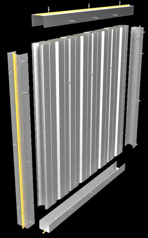
CONTENTS
INTRODUCTION                                                                                                         1      INSTALLATION INFORMATION                                                                                            37
Acoustic performance..................................................................................1                     Doorways and windows............................................................................37
Fire performance.............................................................................................1              Penetrations....................................................................................................37
100% reusable, minimum waste.............................................................1                                  Plumbing and electrical services.........................................................37
Project portfolio................................................................................................2          Shelf loads........................................................................................................37
Companies using KOROK®........................................................................2                             Fixing accessories.......................................................................................37
Industrial and retail applications..............................................................3                           External wall installation............................................................................37
Lift shafts, ducts and stairs........................................................................3                      New Zealand Building Code (NZBC) compliance........................37
Intertenancy applications...........................................................................3                       Quality control................................................................................................38
Steel building and sheds.............................................................................4                      Design guidelines.........................................................................................38
Client feedback.................................................................................................4           Limitations........................................................................................................38
Product Highlights..........................................................................................5               Transport...........................................................................................................38
                                                                                                                            Handling and Storage................................................................................38
KOROK® SYSTEMS SUMMARY TABLE                                                                                         6      Strippable film.................................................................................................38
Table 1 - Fire Rated Systems....................................................................6                           Cleaning.............................................................................................................38
Table 2 - Acoustic Rated Systems.........................................................7                                  On site handling.............................................................................................38
K51 - KOROK® 51 mm Panel.....................................................................8                              Installation.........................................................................................................38
FS1 - 60min fire rated system..................................................................9                            Maintenance....................................................................................................39
FS2 - 120min fire rated system............................................................10                                Material Safety Data Sheet.....................................................................39
FS3 - 180min fire rated system............................................................11                                Specification...................................................................................................39
EX1 - 120min FRR external wall system..........................................12                                           Warranty............................................................................................................39
KIT01 - 60/60/60..........................................................................................13                Disclaimer.........................................................................................................39
KIT06 - 120/120/120.................................................................................14                      Beware of Substitutions............................................................................39
KIT06A - 120/120/60.................................................................................15                      Liability................................................................................................................39
NCS2 - STC58 duct and shaft wall system....................................16                                               Is this publication current?......................................................................39
NCS3 - STC59 apartment intertenancy acoustic rated
                                                                                                                            PANEL PROPERTIES                                                                                                    40
system................................................................................................................17
NCS4 - STC76 Cinema System...........................................................18                                     KOROK® panels.............................................................................................40
                                                                                                                            Loading combinations...............................................................................40
VERTICAL INSTALLATION                                                                                             19        General design notes.................................................................................40
Cutting Panels................................................................................................21            References.......................................................................................................40
Last panel.........................................................................................................22       Manufacturers documents......................................................................40
Screw Placement..........................................................................................23                 Standards..........................................................................................................40
Table 3 - Screw Placement Vertical Installation...........................23
                                                                                                                            KOROK® PANEL PROPERTIES: 78 MM                                                                                      41
C-track................................................................................................................23
Sealant Placement.......................................................................................24                  Vertical span walls........................................................................................41
Final check........................................................................................................25       Horizontal span walls..................................................................................41
Head Track Protection...............................................................................26                      Thermal resistance......................................................................................41
                                                                                                                            Definitions.........................................................................................................41
HORIZONTAL INSTALLATION                                                                                           27        Use of tables...................................................................................................41
Cutting Panels................................................................................................30            Supporting structures................................................................................41
Last panel.........................................................................................................31       Installation note.............................................................................................41
Screw Placement..........................................................................................32                 Table 5 - Shear strength per fastener for the following
Table 4 - Screw Placement Horizontal Installation.....................32                                                    connections....................................................................................................42
C-track................................................................................................................32   Table 6 - Horizontal span..........................................................................42
Sealant Placement.......................................................................................33                  Table 7 - Vertical span................................................................................42
Final check........................................................................................................33
                                                                                                                            KOROK® PANEL PROPERTIES: 51 MM                                                                                      43
CHANGING PANEL ORIENTATION                                                                                        34        Vertical span walls........................................................................................43
Mix of Horizontal and Vertical Panels.................................................34                                    Horizontal span walls..................................................................................43
Changing Panel Direction........................................................................34                          Definitions.........................................................................................................43
                                                                                                                            Use of tables...................................................................................................43
GENERAL CORNERS AND JUNCTIONS                                                                                     35        Supporting structures................................................................................43
                                                                                                                            Installation note.............................................................................................43
Vertical Wall 90º Corner Detail..............................................................35                             Table 8 - Shear strength per fastener for the following
T-Junctions......................................................................................................35         connections....................................................................................................44
                                                                                                                            Table 9 - Horizontal span..........................................................................44
UNSUPPORTED DOOR OPENINGS (MAX. WIDTH                                                                                       Table 10 - Vertical span.............................................................................44
2M)                                 36
Doors in KOROK® Systems.....................................................................36                              KOROK® COMPONENTS SUMMARY                                                                                           45

                                                                                                                            TABLE 11 - KOROK® FASTENERS SPACINGS                                                                                46

                                                                                          KOROK® TECHNICAL AND INSTALLATION MANUAL www.korok.com 0800 773 777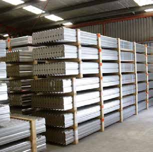
INTRODUCTION
SUPERIOR FIRE AND ACOUSTIC PERFORMANCE WITH CLIP-TOGETHER SIMPLICITY
• BRANZ appraised.
• Roll formed galvanised steel or colour
steel outer shell.
• Lightweight with aerated concrete core.
• Fire ratings up to –/240/240.
• Acoustic ratings up to STC 76.
• Panels interlock with clip-together
simplicity for rapid installation.
• Can be dismantled and reassembled to
accommodate changing requirements.
• Can be installed horizontally or vertically.
When acoustic and fire regulations demand a high FIRE PERFORMANCE
performance, no-risk solution, KOROK® will exceed New
KOROK® delivers proven two-way fire resistance over a long
Zealand Building Code requirements for internal and external
period of time. KOROK® has been tested and appraised by
non-load bearing walls simply and cost effectively.
the Building Research Association of New Zealand (BRANZ).
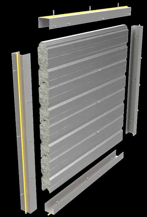
Exceptionally strong yet lightweight, the interlocking panels
can be easily erected by a small crew, making KOROK® much 100% REUSABLE, MINIMUM WASTE
faster to install than conventional wall systems.
KOROK® is manufactured in New Zealand and offers unique
Construction using KOROK® also allows a building to be benefits in terms of sustainability and environmental
made weather resistant much earlier in the construction performance:
cycle allowing internal work and finishing to be started
sooner. • Walls can be reused by simply dismantling the panels
and reinstalling them in another location.
ACOUSTIC PERFORMANCE • The raw components (steel and concrete) are 100%
recyclable.
KOROK®’s inherent mass and interlocking design gives it
outstanding acoustic reduction properties making it highly • Panels are custom manufactured to size, minimising
suitable in buildings where acoustic performance is critical, waste at the factory and on the construction site.
such as cinemas, lecture theatres, apartments, recording
studios and industrial/commercial intertenancy situations. • DECLARE - KOROK has Declare Certification for our
panels, the most accessed sustainability certification
The unique interlocking design eliminates the risk of sound in the building industry https://living-future.org/declare-
“leaks” between panels, and makes installation much faster products/korok
and more simple than traditional systems.
KOROK® TECHNICAL AND INSTALLATION MANUAL www.korok.com 0800 773 777 .1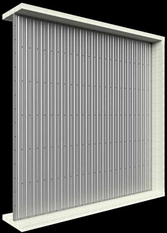
PROJECT PORTFOLIO
                        Event Cinema, Tauranga Crossing
                        Sylvia Park, Auckland
                        La Residence De La Plage, Orewa
                        Christchurch Library
                        Outpatients, Christchurch Hospital
                        The Crossings, Christchurch
                        Auckland University Business School
                        Berkeley Cinemas, Botany Downs
                        Farmers Car Park, Christchurch
                        Grenada Business Park, Wellington
                        Henderson Film Studios, Auckland
                        Lumina Apartments, Auckland
                        Westfield Newmarket, Auckland
                        NZ Post Mail Centres (Auckland, Hamilton,
                        Christchurch)
                        Precinct On Lorne, Auckland

                        COMPANIES USING KOROK®
                        Classic Builders
                        Dominion Constructors
                        Federal Group
                        Fletcher Construction
                        Hawkins Construction
                        Haydn & Rollett Construction
                        Jasmax
                        Jennian Homes
                        Leighs Construction
                        LT McGuinness Ltd
                        Macrennie Construction
                        Morrison Architects
                        Naylor Love
                        Universal Homes
                        Warren and Mahoney
                        Watts & Hughes Construction

.2   KOROK® TECHNICAL AND INSTALLATION MANUAL www.korok.com 0800 773 777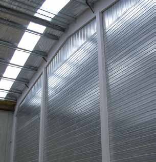
INTRODUCTION
INDUSTRIAL AND RETAIL APPLICATIONS
In factories, warehouses and bulk retail environments,
KOROK® provides strong, solid separation walls that are
secure and fire compliant with high acoustic insulating
properties. In buildings where the interior layout may need
to be reconfigured for future needs, KOROK® is especially
versatile in that it can be easily dismantled and relocated.
Galvanised KOROK® has a highly reflective surface and
when left unlined, can help create a brighter, safer working
environment. Alternatively, KOROK® can be supplied in a
range of colour steel paint finishes.
INTERTENANCY APPLICATIONS
With traditional intertenancy wall systems, it is often difficult
to achieve reliable on-site fire and acoustic performance
due to the complex nature of the installation requirements.
The clip-together simplicity of KOROK® greatly reduces
installation complexity and minimizes the risk of sound
“leaks” or discrepancies in on site acoustic performance.
With a baseline performance of STC 56 and a fire rating
up to FRR –/240/120, KOROK® intertenancy systems for
multi-unit residential projects exceed all Building Code
requirements for both fire and acoustic control.
KOROK® is a popular choice for partition walls in factories,
workshops and other commercial developments where
there are multiple tenants and noise is an issue.
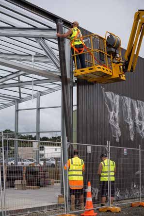
LIFT SHAFTS, DUCTS AND STAIRS
KOROK® offers significant advantages over traditional
construction. Because it can be installed from one side only,
there is no requirement to construct scaffolding inside the
shaft, greatly reducing construction time and costs. Unlike
traditional systems, KOROK® can be installed before the
structure is watertight and also helps prevent water from
entering the building through open shafts.
KOROK® TECHNICAL AND INSTALLATION MANUAL www.korok.com 0800 773 777 .3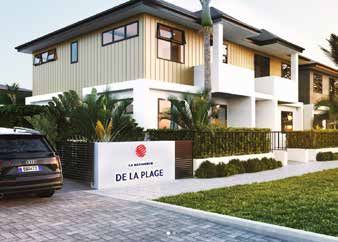
STEEL BUILDING AND SHEDS
KOROK® is especially efficient and economical when
                                                                    CLIENT FEEDBACK
used for fire-rated separation and boundary walls in steel
buildings, sheds and similar structures.
Installation can generally be managed by a three-person             IGNITE ARCHITECTS
team and no cranes are required on site.                            Berkeley Cinemas
The floor slab does not have to be specially engineered
to accommodate the additional weight associated with                “KOROK® is far superior to normal
traditional tilt slab or other similar construction techniques,     construction for a theatre. It took out the
leading to significant cost savings.                                 possibility of there being a flaw by removing
                                                                    a lot of the human error factor. It cut out
                                                                    between six and eight weeks’ worth of
                                                                    construction time.”
                                                                                        – Jeremy Craig, Architect

                                                                    FLETCHER CONSTRUCTION
                                                                    Auckland University Business School

                                                                    “We got two months advantage on the
                                                                    building programme by going to KOROK®.
                                                                    It’s been a test case for Fletcher Building as
                                                                    we look towards introducing KOROK® into
                                                                    our other building projects.”
                                                                                    – Andrew Rolfe, Site Manager

                                                                    SPANTECH BUILDINGS
                                                                    Taupo Motorpark

                                                                    “We were looking for a cost-effective
                                                                    alternative to precast panels. KOROK® is
                                                                    much quicker and shortened the project by
                                                                    two to three weeks on an eight-week project.
                                                                    It was easy to do and the acoustic rating is
                                                                    brilliant.”
                                                                                                  – Marc Osborne

                                                                    MAINZEAL CONSTRUCTION
                                                                    Scene 3 Apartments

                                                                    “The acoustic qualities and fire qualities were
                                                                    quite a selling point and were well over code
                                                                    requirements. KOROK® construction saved
                                                                    us a lot of time, hassle and risk. The system
        KOROK® can be manufactured with a                           is so robust and reliable.”
        colour steel paint finish.                                              – John Williams, Project Manager

.4                                              KOROK® TECHNICAL AND INSTALLATION MANUAL www.korok.com 0800 773 777
PRODUCT HIGHLIGHTS

                                                           KOROK® can be installed horizontally or vertically and
                                                           can be disassembled, relocated or reconfigured to suit
                                                           changing space requirements.

  Exceptionally strong yet lightweight, the interlocking
  panels can be easily erected by a small crew, making
  KOROK® much faster to install than conventional wall
  systems.

                                                           KOROK® panels are custom manufactured to order in
                                                           lengths up to 9.3 metres. This system of manufacture
  KOROK® can provide an effective sound barrier in any     minimises waste both at the factory and on the
  situation where noise is a problem.                      construction site.

KOROK® TECHNICAL AND INSTALLATION MANUAL www.korok.com 0800 773 777                                        .5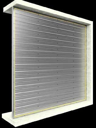
KOROK® SYSTEMS SUMMARY TABLE
TABLE 1 - FIRE RATED SYSTEMS

 SPEC.   STC    FRR         WALL           FRAME     CAVITY    SYSTEM SUMMARY                                                      PAGE
 CODE                       THICKNESS*

 K51     36     -/60/60     51 mm          N/A       N/A       KOROK® 51 mm panels (600 Kg/m3 density)                               8
                                                               KOROK® metal fire flashing is installed to the top C-track
                                                               OR
                                                               13 mm GIB Fyreline® or acceptable GIB® alternatives x 120 mm
                                                               strip with sealant is fixed at 250 mm centres top and bottom,
                                                               using 6g x 32 mm drywall screws.

 FS1      36    -/120/60    78 mm          N/A       N/A       KOROK® 78 mm panels with no linings attached                          9

 FS2      36    -/120/120   78 mm          N/A       N/A       KOROK® 78 mm panels with no linings attached. KOROK® Fire            10
                                                               Flashing is fixed on one side of the top KOROK® C-track
                                                               OR
                                                               13 mm GIB Fyreline® or acceptable GIB® alternatives x 120 mm
                                                               strip with sealant is fixed at 250 mm centres top and bottom,
                                                               using 6g x 32 mm drywall screws.

 FS3      40    -/180/180   104 mm         N/A       N/A       KOROK® 78 mm panels with 13 mm GIB Fyreline® or acceptable           11
                                                               GIB® alternatives on both sides

 EX1      36    -/120/120   78 mm          N/A       N/A       KOROK® 78 mm panels with no linings attached                         12
                                                                                                                        *Nominal thickness

When used as a fire rated system refer to KOROK® Panel Properties section for maximum unsupported spans.

Due to its unique composition, KOROK® provides                       IMPORTANT: In order to satisfy the requirements
exceptional fire resistance over a long period of                    of New Zealand Building Code (Clause C6) relating
time.                                                                to “structural stability during fire”, designers must
                                                                     ensure that KOROK® elements are supported by
To achieve the stated fire resistance ratings, it
                                                                     primary elements that have at least the same fire
is critically important to adhere strictly to the
                                                                     rating as the KOROK® system that is used, unless
design, installation and construction details in this
                                                                     the primary structure lies outside the fire cell.
manual otherwise the fire resistance rating may be
degraded.
KOROK® fire rated wall panels have been
tested and appraised by the Building Research
Association of New Zealand (BRANZ). In some
cases, a fire resistance rating has been based on
opinion from the same organisation.

.6                                           KOROK® TECHNICAL AND INSTALLATION MANUAL www.korok.com 0800 773 777
KOROK® SYSTEMS SUMMARY TABLE
TABLE 2 - ACOUSTIC RATED SYSTEMS
SPEC. STC FRR WALL FRAME CAVITY SYSTEM SUMMARY PAGE
CODE THICKNESS*
KIT01 64 60/60/60 288mm 90mm timber Minimum 86mm KOROK® 51 mm panels (600 Kg/m3 density) 13
frame each overall between + 1 layer 10 mm GIB® Standard plasterboard
side the framing each side
Framing not to Acoustic insulation must be either Autex
touch KOROK® GreenStuf SW90 or Pink Batts R 2.2 each
panel or fire side
flashing
KOROK® metal fire flashing is installed to the
top C-track. KOROK® metal KIT flashing is
installed to horizontal joints.
KIT06 63 120/120/120 315mm 90mm timber 113 mm overall. KOROK® 78 mm panels (400 Kg/m3 density) 14
frame each Framing not to + 1 layer 10 mm GIB® Standard plasterboard
side touch KOROK® each side
panel
KOROK® Fire Flashing is fixed on one side of
the top KOROK® C-track
KIT06A 63 120/120/60 315mm 90mm timber Minimum 113 mm KOROK® 78 mm panels (400 Kg/m3 density) 15
frame each overall between + 1 layer 10 mm GIB® Standard plasterboard
side the framing. each side
Framing not to Acoustic insulation must be either Autex
touch KOROK® GreenStuf SW90 or Pink Batts R 2.2 each
panel side
NCS2 58 -/120/120 175mm 64mm Steel 20mm KOROK® 78 mm panels with a 20mm cavity, 16
stud 64mm steel stud, R1.8 insulation and a layer
of 13 mm GIB Noiseline®
NCS3 59 -/120/120 188mm 64mm Steel 20mm KOROK® 78 mm panels with a 20mm cavity, 17
stud 64mm steel stud, R1.8 insulation and a layer
of 13 mm GIB Noiseline® on one side with
a layer of 13 mm standard plasterboard on
the other side
NCS4 76 -/120/120 600mm N/A 444mm 2 parallel walls of KOROK® 78 mm panels 18
(400 Kg/m3 density) with a 444mm cavity
and a layer of 90mm x 42kg/m2 insulation
attached to one internal face
*Nominal thickness
When used as a fire rated system refer to KOROK® Panel Properties section for maximum unsupported spans.
Due to its unique composition, KOROK® provides IMPORTANT: In order to satisfy the requirements
exceptional fire resistance over a long period of of New Zealand Building Code (Clause C6) relating
time. to “structural stability during fire”, designers must
ensure that KOROK® elements are supported by
To achieve the stated fire resistance ratings, it
primary elements that have at least the same fire
is critically important to adhere strictly to the
rating as the KOROK® system that is used, unless
design, installation and construction details in this
the primary structure lies outside the fire cell.
manual otherwise the fire resistance rating may be
degraded.
KOROK® fire rated wall panels have been
tested and appraised by the Building Research
Association of New Zealand (BRANZ). In some
cases, a fire resistance rating has been based on
opinion from the same organisation.
KOROK® TECHNICAL AND INSTALLATION MANUAL www.korok.com 0800 773 777 .7K51 - KOROK® 51 MM PANEL
SPEC. STC FRR WALL FRAME CAVITY SYSTEM SUMMARY
CODE THICKNESS*
K51 36 -/60/60 51 mm N/A N/A KOROK® 51 mm panels (600 Kg/m3 density)
KOROK® metal fire flashing is installed to the top C-track
OR
13 mm GIB Fyreline® or acceptable GIB® alternatives x 120 mm strip with
sealant is fixed at 250 mm centres top and bottom, using 6g x 32 mm
drywall screws.
*Nominal thickness
KOROK® PANEL SEALANT
KOROK® 51 mm panels are located in KOROK® C-track 60 Beads of fire rated sealant are required around the perimeter
mm high x 51 mm wide x 1.15bmt. The KOROK® C-track is of the KOROK® system. Refer to the installation section of
fixed to the structure at 400 mm centres max, and bedded this publication for more information on sealant application,
on a 6mm bead of fire rated sealant. and to the KOROK® Components Summary (page 45) for
approved sealants.
K51
13 mm GIB Fyreline® 60 x 51 KOROK® metal
or acceptable GIB® KOROK® fire flashing is
alternatives x 120 mm C-track installed to the
strip with sealant is fixed top C-track
at 250 mm centres top
and bottom, using 6g x
32 mm drywall screws.
KOROK® 51 mm
panel density
600 kg/m3 STC
36
FRR
Appraisal No.1059 [2019] -/60/60
.8 KOROK® TECHNICAL AND INSTALLATION MANUAL www.korok.com 0800 773 777FS1 - 60MIN FIRE RATED SYSTEM
SPEC. STC FRR WALL FRAME CAVITY SYSTEM SUMMARY
CODE THICKNESS*
FS1 36 -/120/60 78 mm N/A N/A KOROK® 78 mm panels with no linings attached
*Nominal thickness
KOROK® PANEL SEALANT
KOROK® panels are 78 mm thick, located in KOROK® C-track Beads of fire rated sealant are required around the perimeter
60 mm high x 80 mm wide x 1.15B.M.T. of the KOROK® system. Refer to the installation section of
this publication for more information on sealant application,
KOROK® C-track is fixed to the supporting structure at a
and to the KOROK® Components Summary (page 45) for
maximum of 400 mm centres bedded on a bead of fire-rated
approved sealants.
sealant.
FS1
60 x 80 mm
KOROK®
C-track
KOROK® 78
mm panel
density 400
kg/m3
STC
36
60 x 80 mm
FRR KOROK®
C-track
-/120/60 Appraisal No.559 [2020]
KOROK® TECHNICAL AND INSTALLATION MANUAL www.korok.com 0800 773 777 .9FS2 - 120MIN FIRE RATED SYSTEM
SPEC. STC FRR WALL FRAME CAVITY SYSTEM SUMMARY
CODE THICKNESS*
FS2 36 -/120/120 78 mm N/A N/A KOROK® 78 mm panels with no linings attached. KOROK® Fire
Flashing is fixed on one side of the top KOROK® C-track
*Nominal thickness
KOROK® PANEL KOROK® FIRE FLASHING
KOROK® panels are 78 mm thick, located in KOROK® C-track KOROK® fire flashing is fixed to the panels at 250 mm
60 mm high x 80 mm wide x 1.15B.M.T. centres
KOROK® C-track is fixed to the supporting structure at a OR
maximum of 400 mm centres bedded on a bead of fire-rated
13 mm GIB Fyreline® or acceptable GIB® alternatives x 120
sealant.
mm strip with sealant is fixed at 250 mm centres top and
bottom, using 6g x 32 mm drywall screws.
SEALANT
Beads of fire rated sealant are required around the perimeter
of the KOROK® system. Refer to the installation section of
this publication for more information on sealant application,
and to the KOROK® Components Summary (page 45) for
approved sealants.
FS2
60 x 80 mm KOROK® fire
KOROK® flashing
C-track
KOROK® 78 mm
panel density 400
kg/m3
STC
36
FRR
Appraisal No.559 [2020] -/120/120
.10 KOROK® TECHNICAL AND INSTALLATION MANUAL www.korok.com 0800 773 777FS3 - 180MIN FIRE RATED SYSTEM
SPEC. STC FRR WALL FRAME CAVITY SYSTEM SUMMARY
CODE THICKNESS*
FS3 40 -/180/180 104 mm N/A N/A KOROK® 78 mm panels with 13 mm GIB Fyreline® or acceptable GIB®
alternatives on both sides
*Nominal thickness
KOROK® PANEL JOINTING
KOROK® panels are 78 mm thick, located in KOROK® C-track All screw heads stopped and all sheet joints tape reinforced
60 mm high x 80 mm wide x 1.15B.M.T. and stopped in accordance with the plasterboard
KOROK® C-track is fixed to the supporting structure at a manufacturers recommendations and specifications.
maximum of 400 mm centres bedded on a bead of fire-rated
sealant.
SEALANT
Beads of fire rated sealant are required around the perimeter
LINING of the KOROK® system. Refer to the installation section of
1 layer of 13 mm GIB Fyreline® or acceptable GIB® this publication for more information on sealant application,
alternatives each side of the wall. Full height sheets shall be and to the KOROK® Components Summary (page 45) for
used where possible. Sheets shall be touch fitted. Offset approved sealants.
joints on opposite sides of the wall by 600mm. Linings are
fixed hard to floor.
Plasterboard linings are installed to the manufacturer’s
specification.
FS3
60 x 80 mm
KOROK® C-track
13 mm GIB Fyreline®
or acceptable GIB®
alternatives
KOROK® 78 mm panel 13 mm GIB Fyreline®
density 400 kg/m3
or acceptable GIB®
alternatives
STC
40
FRR
-/180/180 Appraisal No.559 [2020]
KOROK® TECHNICAL AND INSTALLATION MANUAL www.korok.com 0800 773 777 .11EX1 - 120MIN FRR EXTERNAL WALL SYSTEM
SPEC. STC FRR WALL FRAME CAVITY SYSTEM SUMMARY
CODE THICKNESS*
EX1 36 -/120/120 78 mm N/A N/A KOROK® 78 mm Colorsteel® panels (400 Kg/m3 density) with no
linings attached
*Nominal thickness
KOROK® PANEL SEALANT
KOROK® panels are 78 mm thick, located in KOROK® C-track Beads of fire rated sealant are required around the perimeter
60 mm high x 80 mm wide x 1.15B.M.T. on the top and sides of the KOROK® system. Refer to the installation section of
and Base Angle at the bottom. this publication for more information on sealant application,
and to the KOROK® Components Summary (page 45) for
EX1 approved sealants.
KOROK® System EX1 is an all-in-one wall solution for fire,
acoustic and weather protection in external applications with
no doors, windows or other penetrations.
The system comprises KOROK® 78 mm panels, with no
linings attached. Standard KOROK® C-track is used around
the perimeter of the wall, and KOROK® Base Angle at the
bottom of the wall as shown in diagram below.
The standard system has a 120-minute fire rating and a
acoustic rating of STC 36. However, fire ratings up to 240
minutes and acoustic ratings up to STC 76 can be achieved
with specific design.
KOROK® panels for external use are pre-painted and can be
supplied in a wide range of colours.
EX1
KOROK® 78 mm
panel density 400
kg/m3
STC
Base Angle 36
FRR
Appraisal No.722 [2011] -/120/120
.12 KOROK® TECHNICAL AND INSTALLATION MANUAL www.korok.com 0800 773 777KIT01 - 60/60/60
SPEC. STC FRR WALL FRAME CAVITY SYSTEM SUMMARY
CODE THICKNESS*
KIT01 64 60/60/60 288mm 90mm Minimum 86mm KOROK® 51 mm panels (600 Kg/m3 density) + 1 layer 10 mm
timber overall between GIB® Standard plasterboard or plasterboard of equivalent
frame each the framing nominal thickness and density each side
side
Framing not to Acoustic insulation must be either Autex GreenStuf SW90
touch KOROK® or Pink Batts R 2.2 or insulation of an equivalent nominal
panel or fire thickness and density, each side
flashing
KOROK® metal fire flashing is installed to the top C-track.
KOROK® metal KIT flashing is installed to horizontal joints.
*Nominal thickness
KOROK® PANEL panel and spaced at a maximum of 3.0 metres vertically and
KOROK® 51 mm panels are located in KOROK® C-track 60 500 mm horizontally.
mm high x 51 mm wide x 1.15B.M.T. KOROK® panels must
not exceed 12 metres in height. LINING
Frames are lined with 1 layer of 10 mm GIB® Standard
FRAMING plasterboard or plasterboard of equivalent nominal
Frames must be designed to meet the requirements of thickness and density each side of the wall. Joints must
NZBC Part B and consider the loading imposed on them by occur over framing.
the KOROK® wall. Plasterboard linings are installed to the manufacturer’s
Framing may be timber or steel. specification.
Cavity must be 86mm overall. Framing not to touch KOROK® SEALANT
panel or fire flashing. Beads of fire rated sealant are required around the perimeter
of the KOROK® system. Refer to the KOROK® Components
ACOUSTIC INSULATION Summary (page 45) for approved sealants.
Acoustic insulation must be either Autex GreenStuf SW90 or
Pink Batts R 2.2 or insulation of an equivalent nominal thickness and INSTALLATION
density. For system installation, please see the KOROK® Intertenancy
Terraced Housing Systems Manual.
SUPPORT BRACKETS
KOROK® aluminium brackets (PN AB10) are fixed into the
KIT01
60 x 51 mm
Fire flashing KOROK® C-track
1 layer 10 mm GIB® 90 x 45mm framing
Standard plasterboard
or plasterboard of
equivalent nominal 1 layer 10 mm GIB®
thickness and density Standard plasterboard
or plasterboard of
equivalent nominal
thickness and density
KOROK® 51 mm panel
STC density 600 kg/m3
64 Acoustic insulation
Acoustic
insulation
FRR
60/60/60 Appraisal No.1059 [2019]
KOROK® TECHNICAL AND INSTALLATION MANUAL www.korok.com 0800 773 777 .13KIT06 - 120/120/120
SPEC. STC FRR WALL FRAME CAVITY SYSTEM SUMMARY
CODE THICKNESS*
KIT06 63 120/120/120 315mm 90mm Minimum 113 KOROK® 78 mm panels (400 Kg/m3 density) + 1 layer 10 mm
timber mm overall GIB® Standard plasterboard or plasterboard of equivalent
frame between the nominal thickness and density each side
each framing. Framing
side not to touch Acoustic insulation must be either Autex GreenStuf SW90
KOROK® panel or Pink Batts R 2.2 or insulation of an equivalent nominal
or fire flashing thickness and density, each side
KOROK® metal fire flashing is installed to the top C-track.
KOROK® metal KIT flashing is installed to horizontal joints.
*Nominal thickness
KOROK® PANEL panel and spaced at a maximum of 3.0 metres vertically and
KOROK® 78 mm panels are located in KOROK® C-track 60 500 mm horizontally.
mm high x 80 mm wide x 1.15B.M.T. KOROK® panels must
not exceed 14 metres in height. LINING
Frames are lined with 1 layer of 10 mm GIB® Standard
FRAMING plasterboard or plasterboard of equivalent nominal
Frames must be designed to meet the requirements of the thickness and density each side of the wall. Joints must
NZBC Part B, taking into consideration the load imposed on occur over framing.
them by the KOROK® wall. Plasterboard linings are installed to the manufacturer’s
Framing may be timber or steel. specification.
Cavity must be 113 mm overall. Framing not to touch SEALANT
KOROK® panel or fire flashing. Beads of fire rated sealant are required around the perimeter
of the KOROK® system. Refer to the KOROK® Components
ACOUSTIC INSULATION Summary (page 45) for approved sealants.
Acoustic insulation must be either Autex GreenStuf SW90 or
Pink Batts R 2.2 or insulation of an equivalent nominal thickness and INSTALLATION
density. For system installation, please see the KOROK® Intertenancy
Terraced Housing Systems Manual.
SUPPORT BRACKETS
KOROK® aluminium brackets (PN AB10) are fixed into the
KIT06
60 x 80 mm Fire flashing
KOROK® C-track
1 layer GIB® Standard
plasterboard or plasterboard 1 layer GIB® Standard
of equivalent nominal plasterboard or
thickness and density plasterboard of
equivalent nominal
thickness and
90 x 45mm framing
density
KOROK® 78 mm panel
density 400 kg/m3
STC
90 x 45mm framing
Acoustic
63
insulation
FRR
Appraisal No.559 [2020] 120/120/120
.14 KOROK® TECHNICAL AND INSTALLATION MANUAL www.korok.com 0800 773 777KIT06A - 120/120/60
SPEC. STC FRR WALL FRAME CAVITY SYSTEM SUMMARY
CODE THICKNESS*
KIT06A 63 120/120/60 315mm 90mm Minimum 113 mm KOROK® 78 mm panels (400 Kg/m3 density) + 1 layer
timber overall between the 10 mm GIB® Standard plasterboard or plasterboard of
frame framing. Framing equivalent nominal thickness and density each side
each not to touch
side KOROK® panel Acoustic insulation must be either Autex GreenStuf SW90
or Pink Batts R 2.2 or insulation of an equivalent nominal
thickness and density, each side
*Nominal thickness
KOROK® PANEL SUPPORT BRACKETS
KOROK® 78 mm panels are located in KOROK® C-track 60 KOROK® aluminium brackets (PN AB10) are fixed into the
mm high x 80 mm wide x 1.15B.M.T. KOROK® panels must panel and spaced at a maximum of 3.0 metres vertically and
not exceed 12 metres in height. 500 mm horizontally.
FRAMING LINING
Frames must be designed to meet the requirements of Frames are lined with 1 layer of 10 mm GIB® Standard
NZBC Part B and consider the loading imposed on them by plasterboard or plasterboard of equivalent nominal
the KOROK® wall. thickness and density each side of the wall. Joints must
occur over framing.
Cavity must be 113 mm overall. Framing not to touch
KOROK® panel. Plasterboard linings are installed to the manufacturer’s
specification.
ACOUSTIC INSULATION
Acoustic insulation must be either Autex GreenStuf SW90 or SEALANT
Pink Batts R 2.2 or insulation of an equivalent nominal thickness and Beads of fire rated sealant are required around the perimeter
density. of the KOROK® system. Refer to the installation section of
this publication for more information on sealant application,
and to the KOROK® Components Summary (page 45) for
approved sealants.
KIT06A Steel stud option available.
60 x 80 mm KOROK®
C-track
Acoustic insulation
1 layer 10 mm GIB®
Standard plasterboard
1 layer 10 mm GIB® or plasterboard of
Standard plasterboard equivalent nominal
or plasterboard of thickness and density
equivalent nominal
thickness and density
90 x 45mm framing
78 mm KOROK®
STC density 400 kg/m3
63 90 x 45mm framing
FRR
120/120/60 Appraisal No.559 [2020]
KOROK® TECHNICAL AND INSTALLATION MANUAL www.korok.com 0800 773 777 .15NCS2 - STC58 DUCT AND SHAFT WALL SYSTEM
SPEC. STC FRR WALL FRAME CAVITY SYSTEM SUMMARY
CODE THICKNESS*
NCS2 58 -/120/120 175mm 64mm Steel 20mm KOROK® 78 mm panels
stud one side
+ 1 layer 13 mm GIB Noiseline® or plasterboard of equivalent
nominal thickness and density, one side
*Nominal thickness
KOROK® PANEL LINING
KOROK® panels are 78 mm thick, located in KOROK® C-track Frames are lined with 1 layer of 13 mm GIB Noiseline® or
60 mm high x 80 mm wide x 1.15B.M.T. plasterboard of equivalent nominal thickness and density.
KOROK® C-track is fixed at a maximum of 400 mm centres Plasterboard linings are installed to the manufacturer’s
bedded on a bead of fire-rated sealant. specification.
FRAMING JOINTING
Frames must be designed to meet the requirements of the
All fastener heads stopped and all sheet joints tape
NZBC Part B, taking into consideration the load imposed on
reinforced and stopped in accordance with the
them by the KOROK® wall.
manufacturers publication.
Allow a minimum 20mm gap between the framing and the
KOROK® panel. SEALANT
Beads of fire rated sealant are required around the perimeter
ACOUSTIC INSULATION of the KOROK® system. Refer to the installation section of
Acoustic insulation must be either Autex GreenStuf SW75 or this publication for more information on sealant application,
Pink Batts R 1.8 or insulation of an equivalent nominal thickness and and to the KOROK® Components Summary (page 45) for
density. approved sealants.
NCS2
60 x 80 mm
KOROK®
C-track 13 mm GIB Noiseline®
or plasterboard of
equivalent nominal
thickness and density
Acoustic
KOROK® 78 mm insulation
panel density 400
kg/m3
STC
64mm steel stud
58
20mm cavity
FRR
Appraisal No.559 [2020]
-/120/120
.16 KOROK® TECHNICAL AND INSTALLATION MANUAL www.korok.com 0800 773 777NCS3 - STC59 APARTMENT INTERTENANCY
ACOUSTIC RATED SYSTEM
SPEC. STC FRR WALL FRAME CAVITY SYSTEM SUMMARY
CODE THICKNESS*
NCS3 59 -/120/120 188mm 64mm 20mm KOROK® 78 mm panels
Steel stud + 1 layer 13 mm GIB Noiseline® or plasterboard of
one side equivalent nominal thickness and density one side
+ 1 layer 13 mm GIB® Standard or plasterboard of
equivalent nominal thickness and density other side
*Nominal thickness
KOROK® PANEL LINING
KOROK® panels are 78 mm thick, located in KOROK® C-track Frame is lined with 1 layer of 13 mm GIB® Standard or
60 mm high x 80 mm wide x 1.15B.M.T. C-track is fixed at a plasterboard of equivalent nominal thickness and density on one
maximum of 400 mm centres bedded on a bead of fire-rated side and one layer of 13 mm GIB Noiseline® or plasterboard
sealant. of equivalent nominal thickness and density on the other, fixed
vertically with joints over framing one side and direct fixed the
FRAMING other. All plasterboard linings must be fixed in accordance
Frames are 64mm x 34mm x 0.55B.M.T. steel studs, friction with the manufacturer’s fixing instructions.
fitted into C-Section tracks 64mm x 30mm x 0.55B.M.T.
Framing must be installed as per the manufacturer’s
SEALANT
Beads of fire rated sealant are required around the perimeter
instructions.
of the KOROK® system. Refer to the installation section of
this publication for more information on sealant application,
ACOUSTIC INSULATION and to the KOROK® Components Summary (page 45) for
Acoustic insulation must be either Autex GreenStuf SW75 or approved sealants.
Pink Batts R 1.8 or insulation of an equivalent nominal thickness and
density.
NCS3
60 x 80 mm
64mm steel stud KOROK®
C-track
1 layer 13 mm
GIB Noiseline®
or plasterboard of
equivalent nominal
thickness and density
1 layer 13 mm
GIB® Plasterboard
or plasterboard of
equivalent nominal
thickness and
density
Acoustic
STC insulation
59 KOROK® 78 mm
panel density 400
kg/m3
FRR
-/120/120 20mm cavity
Appraisal No.559 [2020]
KOROK® TECHNICAL AND INSTALLATION MANUAL www.korok.com 0800 773 777 .17NCS4 - STC76 CINEMA SYSTEM
SPEC. STC FRR WALL FRAME CAVITY SYSTEM SUMMARY
CODE THICKNESS*
NCS4 76 -/120/120 600mm N/A 444mm 2 parallel walls made up of KOROK® 78 mm panels with a 444mm
cavity, and 1 layer of 90mm x 42kg/m3 insulation attached to one
internal face
*Nominal thickness
KOROK® PANEL SEALANT
KOROK® panels are 78 mm thick, located in KOROK® C-track Beads of fire rated sealant are required around the perimeter
60 mm high x 80 mm wide x 1.15B.M.T. of the KOROK® system. Refer to the installation section of
KOROK® C-track is fixed to the supporting structure at a this publication for more information on sealant application,
maximum of 400 mm centres bedded on a bead of fire-rated and to the KOROK® Components Summary (page 45) for
sealant. approved sealants.
ACOUSTIC INSULATION
1 layer of 90mm x 42kg/m3 insulation or equivalent attached
to one internal face.
NCS4
60 x 80 mm
KOROK®
C-track
Acoustic insulation
KOROK® 78 mm
KOROK® 78 mm
panel density 600
panel density 600
kg/m3
kg/m3
STC
76
FRR
Appraisal No.559 [2020] -/120/120
.18 KOROK® TECHNICAL AND INSTALLATION MANUAL www.korok.com 0800 773 777VERTICAL INSTALLATION
C-track or Angle sections
are fixed to structural
elements (steelwork) at
400 mm centres with Hilti
X-ENP-19 L15 fasteners
When fixing C-track
or Angle sections to
concrete, use 6.5 x 32
Rawl Mushroom spikes
or Hilti DBZ 6/4.5 x 32
mm at 400 mm centres
The C-track or Angle
section must have a
continuous bead of fire
rated sealant between
the track and the
structure to which it is
fixed
Panels are fixed together
with Wafer Tek 10g - 16
x 16 mm screws. For
centres see Step 12
Corner joints must be
sealed with fire rated
sealant (see component
summary for specifics)
KOROK® panels are fixed
to the C-track with Wafer
Tek 10g - 16 x 16 mm
screws both sides (400
mm centres)
KOROK® panels are fixed
to the top and bottom
C-track with Wafer Tek
10g - 16 x 16 mm screws
at 250 mm centres both
sides
KOROK® TECHNICAL AND INSTALLATION MANUAL www.korok.com 0800 773 777 .19VERTICAL INSTALLATION 1 Vertical installation of the KOROK® panels requires the C-track to be fixed to the supporting structure, e.g. walls, columns, portals, soffits and slabs. Plan your setout. 2 To ensure the C-track is sealed to the structure, a continuous bead of fire rated sealant is run around the perimeter before the C-track or Angle sections are laid and fixed. Or the sealant can be applied directly to the C-track before fixing in place. 3 Using a masonry drill bit, pre-drill the C-track at 400 mm centres. 4 Then use the fixings to secure the C-track. .20 KOROK® TECHNICAL AND INSTALLATION MANUAL www.korok.com 0800 773 777
VERTICAL INSTALLATION

5       If the surrounding surface is uneven or
if you’re not sure you have a good seal, add a
continuous bead of sealant around the perimeter
of the C-track where it contacts the surrounding
surface.

6         KOROK® panels must be cut 20 mm shorter
than the structural opening measurement to allow
for fitting.
Pull back a 300mm section of the strippable film on
the ends of the panels before placing the panels in
to the C-track.
Ensure that the first panel is plumbed vertical after
fitting into the C-track. Screw fix the panel into
place to the C-track.
Subsequent panels are placed in a tilt and snap
action.

7         Ensure the tongue and groove are
fully locked to maintain the fire and acoustic
performance. Remove strippable film at the end of
each day’s work.

CUTTING PANELS
8       KOROK® panels can be cut to length and
width with the use of a reciprocating saw or a radial
saw with dust extraction. Diamond cutting discs are
recommended for radial saws.
Where KOROK® panels are trimmed to width, the
cut edge of the panel is fitted into the C-track
and so is always the last panel abutting the wall
or column. The panel is then sealed and fixed in
position as usual.

KOROK® TECHNICAL AND INSTALLATION MANUAL www.korok.com 0800 773 777   .21
VERTICAL INSTALLATION
LAST PANEL

9        Stop short of the end vertical KOROK®
C-track by approximately 1 metre and cut out a
600mm Angle section from the top and bottom
C-track.
Plan ahead and make an allowance for a 50mm
overlap onto the panels installed prior to the
last remaining two panels.

10        Cut your end panel (the last panel) ensuring
that a distance of 500mm remains between panels
for the last two panels to be squeezed into position.

                                                                                                      m
                                                                                                   0m
                                                                                                 60

11      Once the final two panels are in position,
simply replace the Angle and fix to panels. Screw
the C-track and Angle sections to the panels in the
normal fashion.

11A When using 51 mm KOROK panels seal
the 3 close-off panel joints with fire rated sealant to
one side.

.22                                      KOROK® TECHNICAL AND INSTALLATION MANUAL www.korok.com 0800 773 777
VERTICAL INSTALLATION
SCREW PLACEMENT
12 Panels must be screwed together into every panel joint as per the vertical centres in Table 3.
TABLE 3 - SCREW PLACEMENT VERTICAL INSTALLATION
Panel Thickness Wall Height Maximum Centres Sides Placements/Notes
78 mm 0 to 9m 1000mm One
When used as a fire rated system refer to KOROK® Panel Properties section for maximum unsupported spans.
C-TRACK
C-track is fixed to the KOROK® panels at 400 mm centres on both sides on the vertical C-track, and 250 mm
centres on both sides on the horizontal C-track.
At corners where two lengths of KOROK® C-track intersect, the two pieces must be fixed to each other with
one or more Wafer Tek 10g - 16 x 16 mm screws.
400 mm max
1000 mm max
max
250 mm
KOROK® TECHNICAL AND INSTALLATION MANUAL www.korok.com 0800 773 777 .23VERTICAL INSTALLATION SEALANT PLACEMENT 13 Remove any remaining plastic film and then apply a continuous bead of fire rated sealant between the KOROK® C-track and the KOROK® panels as indicated by the yellow line. 14 Fire rated sealant details for top and sides. .24 KOROK® TECHNICAL AND INSTALLATION MANUAL www.korok.com 0800 773 777
VERTICAL INSTALLATION

15     Using Angle as an alternative to C-track.

 FINAL CHECK
 At the completion of the job and at the finish of each day’s work, it is essential that the completed area be
 thoroughly cleaned of all swarf, rivet stems, nails, drillings and screws etc. normally associated with the
 installation of metal KOROK® panels. Remove any remaining strippable film, check all fixings are correctly
 installed, all fire and acoustic sealant is applied correctly.

KOROK® TECHNICAL AND INSTALLATION MANUAL www.korok.com 0800 773 777                                 .25
VERTICAL INSTALLATION
HEAD TRACK PROTECTION
13 mm GIB Fyreline® PROTECTED HEAD TRACK

13 mm GIB Fyreline® or acceptable GIB® alternatives x 120
mm strip with sealant is fixed at 250 mm centres top and
bottom, using 6g x 32 mm drywall screws.

METAL FLASHING PROTECTED HEAD TRACK

KOROK® fire flashing is fixed to the panels at 250 mm
centres, using Wafer Tek 10g - 16 x 16 mm screws.

.26                                          KOROK® TECHNICAL AND INSTALLATION MANUAL www.korok.com 0800 773 777
HORIZONTAL INSTALLATION
                                                                        C-track or Angle sections
                                                                            are fixed to structural
                                                                          elements (steelwork) at
                                                                        400 mm centres with Hilti
                                                                         X-ENP-19 L15 fasteners

                                                                             When fixing C-track
                                                                            or Angle sections to
                                                                           concrete, use 6.5 x 32
                                                                          Rawl Mushroom spikes
                                                                           or Hilti DBZ 6/4.5 x 32
                                                                          mm at 400 mm centres

                                                                        KOROK® panels are fixed
                                                                         together with Wafer Tek
                                                                           10g - 16 x 16 mm into
                                                                         panel joints at 1000mm
                                                                               centres maximum
                                                                          horizontally and at 250
                                                                           mm centres vertically,
                                                                                         one side

                                                                             The C-track or Angle
                                                                              section must have a
                                                                          continuous bead of fire
                                                                           rated sealant between
                                                                                 the track and the
                                                                           structure to which it is
                                                                                             fixed

                                                                            Corner joints must be
                                                                             sealed with fire rated
                                                                                            sealant

                                                                        KOROK® panels are fixed
                                                                          to the top and bottom
                                                                          C-track with Wafer Tek
                                                                        10g - 16 x 16 mm at 400
                                                                         mm centres both sides
              KOROK® panels are fixed                Bottom C-track.
              to the C-track with Wafer               See Step 6 for
             Tek 10g - 16 x 30mm into                 preparation for
            the panel joints at 250 mm                    first panel
                     centres both sides

KOROK® TECHNICAL AND INSTALLATION MANUAL www.korok.com 0800 773 777                   .27
HORIZONTAL INSTALLATION 1 Horizontal Installation of the KOROK® panels requires the C-track to be fixed to the supporting structure, e.g. walls, columns, portals etc. Plan your setout. The top of the last vertical C-track must be cropped as per Step 10 prior to installation, to allow the top and last horizontal panel to be installed. 2 To ensure the C-track is sealed to the structure, a continuous bead of fire rated sealant is run around the perimeter before the C-track or Angle sections are laid and fixed. Or the sealant can be applied directly to the C-track before fixing in place. The soffit track will generally be two Angles. See Last Panel details starting at Step 10. 3 Using a masonry drill bit, pre-drill the C-track at 400 mm centres. 4 Then use the fixings to secure the C-track. .28 KOROK® TECHNICAL AND INSTALLATION MANUAL www.korok.com 0800 773 777
HORIZONTAL INSTALLATION

5       If the surrounding surface is uneven or
if you’re not sure you have a good seal, add a
continuous bead of sealant around the perimeter
of the C-track where it contacts the surrounding
surface.

6        For horizontal installs where the wall
width is greater than 5.0m OR where the load is
transferred to the ground (e.g. 4-sided plant room),
grout or a panel nose must be used in the bottom
C-track.

6.1      Grout is poured into the bottom C-track
just prior to the installation of the KOROK® panels.
This forms a bearing surface for the female end of
the panel.
The cementitious grout must be non-shrink high
performance (Hilti® CM651-48 or similar).
Fill the C-track to a depth of 25-30mm. Any
overflow when the panel is placed in the C-track
must be wiped off immediately.
ENSURE THE FIRST PANEL IS LEVEL AFTER
FITTING INTO THE TRACK AND GROUT AND FIX
OFF.

                       OR

6.2     Alternatively the male nose of the top panel
can be cut off and placed in the female end of the
bottom panel to provide the same support.
ENSURE THE FIRST PANEL IS LEVEL AFTER
FITTING INTO THE TRACK AND FIX OFF.

KOROK® TECHNICAL AND INSTALLATION MANUAL www.korok.com 0800 773 777   .29
HORIZONTAL INSTALLATION 7 KOROK® panels must be cut 30mm shorter than the structural opening measurement to allow for fitting. Pull back a 300mm section of the strippable film on the ends of the panels before placing the panels in to the C-track. Ensure that the first panel is level after fitting into the C-track. Screw fix the first panel into place to the C-track before installing the next panel. Subsequent panels are placed in a tilt and snap action. 8 Ensure the panels are clicked together correctly to maintain the fire and acoustic performance. Remove strippable film at the end of each day’s work. CUTTING PANELS 9 KOROK® panels can be cut to length and width with the use of a reciprocating saw or a radial saw with dust extraction. Diamond cutting discs are recommended for radial saws. Where KOROK® panels are trimmed to width, the cut edge of the panel is fitted into the C-track and so is always the last panel abutting the floor or soffit. The panel is then sealed and fixed in position as usual. .30 KOROK® TECHNICAL AND INSTALLATION MANUAL www.korok.com 0800 773 777
HORIZONTAL INSTALLATION
LAST PANEL
10       To get the last horizontal panel in, cut out
a 300mm angle section from each of the side
C-tracks. Keep these two 300mm angle sections
for use in Step 12.

11     Keep placing the panels and fixing them to
the panel below.

12      Once the last panel is in position, fix the
pieces of C-track that were removed in Step 10,
back in place. Fire-rated sealant is then applied.

13      Angle is then fixed to the soffit at 400 mm
centres, then fixed to the panel at 400 mm centres.
Fire rated sealant is applied.

KOROK® TECHNICAL AND INSTALLATION MANUAL www.korok.com 0800 773 777   .31
You can also read