FRAMOS Industrial Depth Camera D400e Series - USER MANUAL Version 1.5.0 from 2021-07-15
←
→
Page content transcription
If your browser does not render page correctly, please read the page content below
FRAMOS Industrial Depth Camera D400e Series
USER MANUAL

Version 1.5.0 from 2021-07-15 www.framos.com
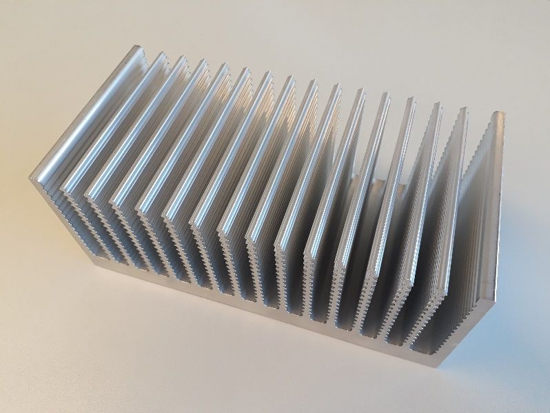
Table of Contents
 Description and Features .............................................................................................. 8
1.1 Description .............................................................................................................................................. 8

1.2 Features .................................................................................................................................................. 8

1.3 System Requirements ............................................................................................................................ 8

 Introduction.................................................................................................................... 9
2.1 Purpose of this Document ...................................................................................................................... 9

2.2 Terminology ............................................................................................................................................ 9

2.3 Stereo Vision Depth Technology Overview .......................................................................................... 10

 Component Overview ...................................................................................................11
3.1 Stereo Depth Module ............................................................................................................................ 11

3.2 Left and Right Imagers ......................................................................................................................... 12

3.3 Infrared Projector .................................................................................................................................. 13

3.4 Color Sensor ......................................................................................................................................... 14

3.5 Inertial Measurement Unit .................................................................................................................... 15

3.6 Image Signal Processor ....................................................................................................................... 15

3.7 FRAMOS D4 Visual Processing Board ................................................................................................ 15

 FRAMOS Depth Camera D400e Series .......................................................................17
4.1 Depth Camera Properties ..................................................................................................................... 17

4.2 Mechanical Dimensions ........................................................................................................................ 18

4.3 Physical Interfaces................................................................................................................................ 20
 4.3.1 Ethernet M12 connector, X-Coded, Female .................................................................................... 20
 4.3.2 Power M8 connector, A-Coded, Male .............................................................................................. 21

4.4 Thermal Control .................................................................................................................................... 22

4.5 Storage and Operating Conditions ....................................................................................................... 22

4.6 Power Consumption ............................................................................................................................. 22

4.7 Depth Camera Depth Origin Reference ............................................................................................... 23

FRAMOS Industrial Depth Camera D400e Series - User Manual
Version 1.5.0 from 2021-07-15 2 of 63
4.8 Labels on the Camera .......................................................................................................................... 24

 FRAMOS Depth Camera D400e Module Variant .........................................................25
5.1 D400e Module Components ................................................................................................................. 25

5.2 D400e Module Variant Connectors Pinout ........................................................................................... 26
 5.2.1 Ethernet Connector J3 ..................................................................................................................... 27
 5.2.2 Power and IO Connector J6 ............................................................................................................. 28

5.3 Thermal Design Consideration ............................................................................................................. 29

5.4 Mechanical Drawings ........................................................................................................................... 29
 5.4.1 FRAMOS D4 Visual Processing Board ............................................................................................ 29
 5.4.2 Depth Module Interposer .................................................................................................................. 29
 5.4.3 Depth Module Cable Bracket ........................................................................................................... 30
 5.4.4 RGB Module Including Cover ........................................................................................................... 30
 5.4.5 RGB Interconnect ............................................................................................................................. 30

 Optimum Thermal Conditions .......................................................................................31
6.1 Fundamentals of the Camera’s Heat Dissipation ................................................................................. 31

6.2 Operating Conditions for Different Temperatures ................................................................................ 32

6.3 Maximum Operating Ambient Temperatures ....................................................................................... 35

6.4 Summary of Operating Conditions and Temperatures ......................................................................... 35

 Mounting and Deployment............................................................................................37
7.1 Camera Mounting ................................................................................................................................. 37

7.2 Application of External Cabling............................................................................................................. 38

7.3 Cleaning Procedures ............................................................................................................................ 38

 Functional Specification................................................................................................39
8.1 Stream Configurations Possible ........................................................................................................... 39

8.2 Depth Field of View (FOV) .................................................................................................................... 40

8.3 Minimum-Z Depth ................................................................................................................................. 40

8.4 Depth Quality Specifications................................................................................................................. 41

8.5 Depth Camera Functions ...................................................................................................................... 42

8.6 Color Camera Functions ....................................................................................................................... 42

8.7 Inertial Measurement Unit Streams ...................................................................................................... 43

FRAMOS Industrial Depth Camera D400e Series - User Manual
Version 1.5.0 from 2021-07-15 3 of 63
8.8 D400e Camera Specific Features ........................................................................................................ 43
 8.8.1 Packet Size ...................................................................................................................................... 43
 8.8.2 Inter Packet Delay ............................................................................................................................ 44
 8.8.3 Heartbeat Time ................................................................................................................................. 44
 8.8.4 Inter Cam Sync Mode....................................................................................................................... 44
 8.8.5 Output Trigger Enabled .................................................................................................................... 45
 8.8.6 User Output Level ............................................................................................................................ 45
 8.8.7 Line Debouncer Time ....................................................................................................................... 45
 8.8.8 RGB/Stereo Synchronization ........................................................................................................... 46
 8.8.9 Syncer Mode .................................................................................................................................... 47

 Firmware Updates ........................................................................................................49
9.1 Firmware Update Interactive Mode ...................................................................................................... 49
 9.1.1 Parallel Firmware Update ................................................................................................................. 50

9.2 Firmware Update Non-Interactive Mode .............................................................................................. 51

9.3 IP Address Conflict ............................................................................................................................... 51
 9.3.1 Interactive Mode ............................................................................................................................... 51
 9.3.2 Non-interactive Mode ....................................................................................................................... 52

 Software .......................................................................................................................53
10.1 FRAMOS Camera Suite SDK ............................................................................................................... 53
 10.1.1 Set IP Configuration ..................................................................................................................... 53
 10.1.2 Manage Camera Calibration Tables ............................................................................................ 56

10.2 Intel® RealSense™ Software Development Kit 2.0 ............................................................................. 57

 Troubleshooting ............................................................................................................58

 Regulatory Compliance ................................................................................................59

 Accessories ..................................................................................................................61

 References ...................................................................................................................62

 Revision History............................................................................................................63

FRAMOS Industrial Depth Camera D400e Series - User Manual
Version 1.5.0 from 2021-07-15 4 of 63
List of Figures
Figure 1 – M12 Connector PIN Layout ....................................................................................20
Figure 2 – Example of connecting M12 to RJ45, T568B termination .........................................21
Figure 3 – M8 Connector PIN Layout ......................................................................................21
Figure 4 – Depth Camera D415e Depth Origin Reference ........................................................23
Figure 5 – Depth Camera D435e Depth Origin Reference ........................................................23
Figure 6 – Depth Camera D455e Depth Origin Reference ........................................................24
Figure 7 – FRAMOS D400e Module Components Overview ....................................................25
Figure 8 – Connecting Interposer Cables to FRAMOS D4 Visual Processing Board ...................26
Figure 9 – FRAMOS D4 Visual Processing Board Ethernet Connector ......................................27
Figure 10 – FRAMOS D4 Visual Processing Board Power and IO Connector ............................28
Figure 11 – FRAMOS D4 Visual Processing Board Dimensions ................................................29
Figure 12 – Depth Module Interposer Dimensions....................................................................29
Figure 13 – D435e Depth Module Cable Bracket Dimensions ..................................................30
Figure 14 – D415e Depth Module Cable Bracket Dimensions ..................................................30
Figure 15 – D455e Depth Module Cable Bracket Dimensions ..................................................30
Figure 16 – RGB Module Including Cover Dimensions .............................................................30
Figure 17 – RGB Interconnect Dimensions ..............................................................................30
Figure 18 – Hottest Part of the Camera Housing ......................................................................31
Figure 19 – D400e Series Camera Body Back Side ................................................................37
Figure 20 – D400e M8 Pin 3 Behavior ....................................................................................45
Figure 21 – D400e Line Debouncer Time ................................................................................46
Figure 22 – D400e Series Camera Synchronized Streams .......................................................46
Figure 23 – D400e Series Camera Streams out of Synchronization ..........................................47
Figure 24 – Syncer Default Mode ...........................................................................................48
Figure 25 – Syncer Wait-For-Frameset Mode ..........................................................................48
Figure 26 - Tool UpdateFirmware Part 1 ..................................................................................49
Figure 27 – Tool UpdateFirmware Part 2 .................................................................................49
Figure 28 - Tool UpdateFirmware Parallel Part 1 ......................................................................50
Figure 29 – Tool UpdateFirmware Parallel Part 2 ......................................................................50
Figure 30 – Selecting one device in noninteractive mode .........................................................51
Figure 31 – IP address conflict ...............................................................................................52
Figure 32 - IP address conflict when selecting all devices ........................................................52
Figure 33 – IP address conflict, procedure terminated..............................................................52
Figure 34 – Tool ConfigureIp Part 1.........................................................................................54
Figure 35 – Tool ConfigureIp Part 2.........................................................................................54
Figure 36 – IP address conflict warning message ....................................................................55
Figure 37 – ConfigureIp tool arguments...................................................................................55
Figure 38 – Verification of status of DHCP protocol ..................................................................55
Figure 39 – Verification of status of permanent IP address ........................................................56
Figure 40 – Tool CalibrationTables Part1 .................................................................................56
Figure 41 – Tool CalibrationTables Part2 .................................................................................57

List of Tables
Table 1 - Terminology ............................................................................................................. 9

FRAMOS Industrial Depth Camera D400e Series - User Manual
Version 1.5.0 from 2021-07-15 5 of 63

Table 2 – D430 Depth Module Properties ...............................................................................11
Table 3 – D410 Depth Module Properties ...............................................................................11
Table 4 – D450 Depth Module Properties ...............................................................................11
Table 5 – D430 Imager Properties ..........................................................................................12
Table 6 – D410 Imager Properties ..........................................................................................12
Table 7 – D450 Imager Properties ..........................................................................................12
Table 8 – D430 infrared projector properties............................................................................13
Table 9 – D410 infrared projector properties............................................................................13
Table 10 – D415e/D435e Color Sensor Properties..................................................................14
Table 11 – D455e Color Sensor Properties .............................................................................14
Table 12 – IMU Specifications ................................................................................................15
Table 13 – ISP Properties .......................................................................................................15
Table 14 – FRAMOS D4 Visual Processing Board Key Components ........................................16
Table 15 – FRAMOS D4 Visual Processing Board Dimensions .................................................16
Table 16 – FRAMOS Depth Camera D400e Series Properties..................................................17
Table 17 – D400e Series Camera Dimensions ........................................................................19
Table 18 – M12 Connector PIN Layout and Description ...........................................................20
Table 19 – M8 Connector PIN Layout and Description .............................................................21
Table 20 – Storage and Operating Conditions .........................................................................22
Table 21 – D400e Series Camera Power Consumption ...........................................................22
Table 22 – Camera Label Information ......................................................................................24
Table 23 – J3 Pin Assignment ................................................................................................27
Table 24 – J6 Pin Assignment ................................................................................................28
Table 25 – D400e Maximum Power Consumption ...................................................................31
Table 26 – D400e Operating Temperature ..............................................................................32
Table 27 – Operating Conditions for Different Temperatures .....................................................32
Table 28 – Heat Dissipation Elements .....................................................................................34
Table 29 – Maximum Operating Ambient Temperatures ...........................................................35
Table 30 – Example of Possible Streams on Gigabit Ethernet Network......................................39
Table 31 – Depth FOV ...........................................................................................................40
Table 32 – Minimum-Z Depth .................................................................................................40
Table 33 – Depth Quality Specifications for FRAMOS D400e Series Camera ............................41
Table 34 – Depth Camera Functions ......................................................................................42
Table 35 – Color Camera Functions........................................................................................43
Table 36 - Inertial Measurement Unit Streams .........................................................................43
Table 37 – Revision History ....................................................................................................63

List of Abbreviations
 Abbreviation Explanation
 AR Anti-Reflective
 DC Direct Current
 DHCP Dynamic Host Communication Protocol
 DOF Degrees of Freedom
 FOV Field of View
 FOP Field of Projection
 GND Ground

FRAMOS Industrial Depth Camera D400e Series - User Manual
Version 1.5.0 from 2021-07-15 6 of 63

I/O Input/Output
 IN Input
 IP Internet Protocol
 IR Infrared
 ISP Image Signal Processor
 LLA Link-Local Address
 NIC Network Interface Card
 OUT Output
 PHY Physical Layer
 POE Power Over Ethernet
 RMA Return Material Authorization
 SDK Software Development Kit
 TBD To Be Determined

FRAMOS Industrial Depth Camera D400e Series - User Manual
Version 1.5.0 from 2021-07-15 7 of 63
Description and Features 1.1 Description The FRAMOS Industrial Depth Camera D400e Series (D400e Series) are built with Intel® RealSense™ technology. The depth cameras have industrial M12 ethernet and M8 power connectors. Its water and dust resistant housing is optimized for industrial environments. The D400e Series are ideal for OEMs and integrators who need 3D as well as 2D vision in their products and applications. The D400e Series are compatible with the Cross-platform SDK for Intel® RealSense™ devices, enabling multiple programming languages, wrappers, sample code and tools. D435e and D455e camera models, featuring global shutter, wide field of view sensors, are especially suitable for applications with fast motion. 1.2 Features Gigabit Ethernet data transmission Data transfer up to 100m in length Single cable solution for both power & data via PoE Increased data transmission reliability with packet resend functionality Intel® RealSense™ SDK 2.0 compatible Onboard depth calculation with Intel® RealSense™ Vision Processor D4 Projector with unstructured light in IR spectrum for enhanced depth quality IP66 dust and water-proof housing for industrial environments, IP67 on project basis Secure cable connections with threaded M12 and M8 plugs Synchronization with external events Simultaneous depth and RGB streaming at profile 1280 x 720 @ 30fps 1.3 System Requirements Host PC Operating System: Microsoft® Windows® 10 Linux Ubuntu 16.04 (or newer) Host PC Architecture: x86_64 ARM64 (NVIDIA® Jetson™ platform) Hardware: Gigabit Network Interface Card (NIC) FRAMOS Industrial Depth Camera D400e Series - User Manual Version 1.5.0 from 2021-07-15 8 of 63
Introduction
2.1 Purpose of this Document
This document captures the specifications and the design–in details for the FRAMOS Industrial
Depth Camera D400e Series. This document provides information necessary to understand and
implement the camera system.

2.2 Terminology
 Term Description
 6DOF Six degrees of freedom (6DoF) refers to the freedom of
 movement of a rigid body in three-dimensional space.
 Forward/back, up/down, left/right, pitch, yaw, roll.
 Stereo Depth The distance between the center of the left and right imagers in
 Baseline a stereo camera.
 Depth Depth video streams are like color video streams except each
 pixel has a value representing the distance away from the
 camera instead of color information.
 FOV Field of View (FOV) describes the angular extent of a given
 scene that is imaged by a camera. A camera's FOV can be
 measured horizontally, vertically, or diagonally.
 IR Projector This refers to the source of infrared (IR) light used for illuminating
 a scene, object, or person to collect depth data.
 Imagers Depth camera system uses a pair of cameras referred as imagers
 to calculate depth. They are identical cameras configured with
 identical settings.
 Image Signal Image processing functions to enhance color image quality.
 Processor (ISP)
 Left imager From the perspective of the stereo camera looking out at the
 world, the left imager is on the left side of the camera module.
 Thus, when the user is facing the D400e camera, the left imager
 is on the right side of the camera module.
 Lens This refers to the optical component of an imager in the D4
 camera. Its purpose is to focus the incoming light rays onto the
 CMOS chip in the imager.
 Table 1 - Terminology

FRAMOS Industrial Depth Camera D400e Series - User Manual
Version 1.5.0 from 2021-07-15 9 of 63
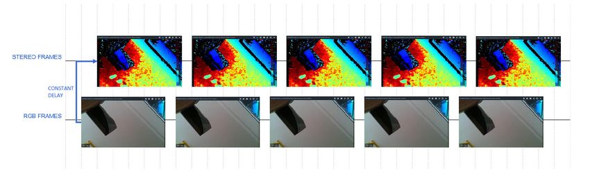
2.3 Stereo Vision Depth Technology Overview
The FRAMOS Industrial Depth Camera D400e Series use stereo vision to calculate depth. The
stereo vision implementation consists of a left imager, right imager, and an optional infrared
projector. The infrared projector projects non-visible static IR pattern to improve depth accuracy in
scenes with low texture. The left and right imagers capture the scene and send image data to the
vision processor. The vision processor calculates depth values for each pixel in the image by
correlating points on the left image to the right image. The depth pixel values are processed to
generate a depth frame. Subsequent depth frames create a depth video stream.

FRAMOS Industrial Depth Camera D400e Series - User Manual
Version 1.5.0 from 2021-07-15 10 of 63
Component Overview The information provided in this chapter on Intel RealSense components are taken from the Intel® RealSense™ D400 Series Product Family datasheet. For mechanical drawings and further details please refer to Intel® RealSense™ D400 Series Product Family [Ref-1]. 3.1 Stereo Depth Module The stereo depth module used in the D435e camera is the Intel® RealSense™ D430, D415e implements Intel® RealSense™ D410 depth module, while D455e implements Intel® RealSense™ D450 depth module. Properties of the Intel® RealSense™ depth modules are as follows: D430 Baseline 50mm Left/Right Imagers Type Wide Depth FOV HD H:87°±3° / V:58°±1° / D:95°±3° Depth FOV VGA H:75°±3° / V:62°±1° / D:89°±3° IR Projector Wide Module Dimensions (mm) X=70.7mm / Y=14mm / Z=10.53mm Table 2 – D430 Depth Module Properties D410 Baseline 55mm Left/Right Imagers Type Standard Depth FOV HD H:65°±2° / V:40°±1° / D:72°±2° Depth FOV VGA H:50°±2° / V:40°±1° / D:61°±2° IR Projector Standard Module Dimensions (mm) X:74.7mm / Y:10mm / Z:4.7mm Table 3 – D410 Depth Module Properties D450 Baseline 95mm Left/Right Imagers Type Wide Depth FOV HD H:87°±3° / V:58°±1° / D:95°±3° Depth FOV VGA H:75°±3° / V:62°±1° / D:89°±3° IR Projector Wide Module Dimensions (mm) X:119.5mm / Y:17.4mm / Z:10.53mm Table 4 – D450 Depth Module Properties Notes: H – Horizontal, V – Vertical, D – Diagonal, X – Length, Y – Breadth, Z – Thickness Depth FOV specified at 2 meters Due to mechanical tolerances of +/-5%, Max and Min FOV values can vary from lens to lens and module to module by ~ +/- 3° FRAMOS Industrial Depth Camera D400e Series - User Manual Version 1.5.0 from 2021-07-15 11 of 63
3.2 Left and Right Imagers
 D430
 Image Sensor OmniVision OV9282
 Active Pixels 1280 X 800
 Sensor Aspect Ratio 8:5
 Format 10-bit RAW
 F Number f/2.0
 Focal Length 1.93mm
 Filter Type None
 Focus Fixed
 Shutter Type Global Shutter
 Imager Field of View H:91.2° / V:65.5° / D:100.6°
 Distortion
3.3 Infrared Projector
The infrared projector improves the ability of the stereo camera system to determine depth by
projecting a static infrared pattern on the scene to increase texture on low texture scenes. The
infrared projector meets class 1 laser safety under normal operation. The power delivery and laser
safety circuits are on the stereo depth module. The infrared projector is referred as Standard or
Wide based on field of projection.

 D430 / D450
 Projector Infrared
 Pattern Type Static
 Vertical-cavity surface-emitting laser
 Illuminating Component
 (VCSEL) + Optics
 Laser Controller PWM
 Optical Power 360mW average, 4.25W peak
 Laser Wavelength 850nm ± 10 nm nominal @ 20°C
 Class 1, IEC 60825-1:2007 Edition 2, IEC
 Laser Compliance
 60825-1:2014 Edition 3
 Field of Projection H:90°±3° / V:63°±3° / D:99°±3°
 Table 8 – D430 infrared projector properties

 D410
 Projector Infrared
 Pattern Type Static
 Vertical-cavity surface-emitting laser
 Illuminating Component
 (VCSEL) + Optics
 Laser Controller PWM
 Optical Power 360mW average, 440mW peak
 Laser Wavelength 850nm ± 10 nm nominal @ 20°C
 Class 1, IEC 60825-1:2007 Edition 2, IEC
 Laser Compliance
 60825-1:2014 Edition 3
 Field of Projection H:64°±3° / V:41°±3° / D:72°±3°
 Table 9 – D410 infrared projector properties

FRAMOS Industrial Depth Camera D400e Series - User Manual
Version 1.5.0 from 2021-07-15 13 of 63
3.4 Color Sensor
The color sensor on the stereo depth module in addition to color image provides texture information.
Usages for the texture information include overlay on a depth image to create a color point cloud
and overlay on a 3D model for reconstruction.

 D415e / D435e
 Image Sensor OmniVision OV2740
 Color Image Signal Processor Discrete
 Active Pixels 1920 X 1080
 Sensor Aspect Ratio 16:9
 Format 10-bit RAW RGB
 F Number f/2.0
 Focal Length 1.88mm
 Filter Type IR Cut Filter
 Focus Fixed
 Shutter Type Rolling Shutter
 Imager Field of View H: 69.4° / V:42.5° / D:77.0°
 Distortion
3.5 Inertial Measurement Unit
Inertial Measurement Unit (IMU) contains sensors which allow measurement of both directional
movement and rotation. Framos D400e depth cameras generate and transmit the gyro and
accelerometer samples independently, as the inertial sensors exhibit different FPS rates
(200/400Hz for gyro, 63/250Hz for accelerometer).

 D435e / D415e / D455e
 Degrees of Freedom 6
 Acceleration Range ±4g
 Accelerometer Sample Rate1 62.5, 250 (Hz)
 Gyroscope Range ±1000 deg/s
 Gyroscope Sample Rate2 200, 400 (Hz)
 Table 12 – IMU Specifications
NOTES:
1. The sample rate may differ from the absolute specified sample rate by ±5%. It is advised to rely
on the sample timestamp.
2. The sample rate may differ from the absolute specified sample rate by ±0.3%.

3.6 Image Signal Processor
The color sensor data is sent to an Image Signal processor (ISP) for a color image quality
enhancement. The enhanced image is sent to the onboard SoC for further processing.

 D435e / D415e / D455e
 ISP RTS5845
 Interface to Color Sensor MIPI CSI-2, 1x Lane
 Interface to SoC MIPI CSI-2, 2x Lanes
 Table 13 – ISP Properties

3.7 FRAMOS D4 Visual Processing Board
FRAMOS D4 Visual Processing Board with integrated Intel® RealSense™ Vision Processor D4 for
depth calculation, provides a Gigabit Ethernet interface, Power over Ethernet (PoE) and additional
GPIOs for external triggering or user output.

For a module variant, ethernet, power supply and GPIOs can be connected directly to the board
without soldering via wire to board connectors (see Chapter 5.2).

 FRAMOS D4 Visual Processing Board Key Components

 Processing unit that implements the control and
 System on Chip (SoC) image data processing, external triggering and data
 link layer of the Ethernet

FRAMOS Industrial Depth Camera D400e Series - User Manual
Version 1.5.0 from 2021-07-15 15 of 63
Intel® RealSense™ Vision Processor D4 for depth
 D4 Vision Processor
 calculation
 Image processing functions to enhance color image
 Color Image Signal Processor (ISP)
 quality
 Inertial Measurement Units allow measurement of
 Inertial Measurement Unit (IMU)
 directional movement and rotation
 Implements the physical layer of the Ethernet
 Gigabit Ethernet Transceiver
 (Ethernet PHY)
 Table 14 – FRAMOS D4 Visual Processing Board Key Components

 FRAMOS D4 Visual Processing Board Dimensions
 Module Dimensions (mm) X=93mm / Y=40mm / Z=15mm
 Table 15 – FRAMOS D4 Visual Processing Board Dimensions

FRAMOS Industrial Depth Camera D400e Series - User Manual
Version 1.5.0 from 2021-07-15 16 of 63
FRAMOS Depth Camera D400e Series
4.1 Depth Camera Properties
 FRAMOS Depth FRAMOS Depth FRAMOS Depth
 Camera D415e Camera D435e Camera D455e
 Intel® RealSense™ Intel® RealSense™ Intel® RealSense™
 Depth Module
 Depth Module D410 Depth Module D430 Depth Module D450
 Left/Right
 Standard Wide Wide
 Imagers Type
 1280 x 720 px 1280 x 720 px 1280 x 720 px
Depth Resolution
 (rolling shutter) (global shutter) (global shutter)
 H:65°±2° / V:40°±1° / H:87°±3° / V:58°±1° / H:87°±3° / V:58°±1° /
 Depth FOV HD
 D:72°±2° D:95°±3° D:95°±3°
 H:50°±2° / V:40°±1° / H:75°±3° / V:62°±1° / H:75°±3° / V:62°±1° /
 Depth FOV VGA
 D:61°±2° D:89°±3° D:89°±3°
 IR Projector Standard Wide Wide
 IR Projector H:64°±3° / V:41°±3° / H:90°±3° / V:63°±3° / H:90°±3° / V:63°±3° /
 FOP D:72°±3° D:99°±3° D:99°±3°
 Color Sensor OV2740 OV2740 OV9782
 1920 x 1080 px 1920 x 1080 px 1280 x 720 px
 Color Resolution
 (rolling shutter) (rolling shutter) (global shutter)
 Color Camera H: 69.4° / V:42.5° / H: 69.4° / V:42.5° / H:90.0° / V:65.0° /
 FOV D:77.0° D:77.0° D:98.0°
 Bosch BMI055 6-axis Bosch BMI055 6-axis Bosch BMI055 6-axis
 IMU
 inertial sensor inertial sensor inertial sensor
 Operating range 0,2m – 10m 0,2m – 10m 0,3m – 20m
 Power
 6W (AUX) / 7W (PoE) 6W (AUX) / 7W (PoE) 6W (AUX) / 7W (PoE)
 consumption
 Dimensions 100mm x 47mm x 100mm x 47mm x 132mm x 47mm x
 (L x H x W) 38mm 38mm 41mm
 Mounting holes
 4 x M3 ↧ 3,2mm 4 x M3 ↧ 3,2mm 4 x M4 ↧ 5,0mm
 (backside)
 Camera Weight 250 grams 250 grams 395 grams
 Protection Glass AR coating, scratch resistant (6H)
Housing material Aluminum, anodized
 Table 16 – FRAMOS Depth Camera D400e Series Properties

FRAMOS Industrial Depth Camera D400e Series - User Manual
Version 1.5.0 from 2021-07-15 17 of 63
4.2 Mechanical Dimensions
Front View D435e

Front View D415e

Front View D455e

FRAMOS Industrial Depth Camera D400e Series - User Manual
Version 1.5.0 from 2021-07-15 18 of 63
Side View D435e/D415e

Side View D455e

Back View D435e/D415e

Back View D455e

 Table 17 – D400e Series Camera Dimensions

FRAMOS Industrial Depth Camera D400e Series - User Manual
Version 1.5.0 from 2021-07-15 19 of 63
4.3 Physical Interfaces FRAMOS D400e series cameras are equipped with two physical interfaces: M12 Ethernet connector for data interface M8 Power connector for power and I/O interfaces 4.3.1 Ethernet M12 connector, X-Coded, Female The Ethernet interface provides configuration access to the camera and is also used for image data transmission. Figure 1 – M12 Connector PIN Layout The M12 connector is a circular connector, pins assigned like shown in Table 18. Ethernet 1000BaseT, 802.3 compliant, ANSI/TIA-568 T568B termination M12 Pin Signal ID/T568B color Description 1 1 (BI_DA+, White/orange stripe) Bi-directional pair A+ 2 2 (BI_DA-, Orange solid) Bi-directional pair A- 3 3 (BI_DB+, White/green stripe) Bi-directional pair B+ 4 6 (BI_DB-, Green solid) Bi-directional pair B- 5 7 (BI_DD+, White/brown stripe) Bi-directional pair D+ 6 8 (BI_DD-, Brown solid) Bi-directional pair D- 7 5 (BI_DC-, White/blue stripe) Bi-directional pair C- 8 4 (BI_DC+, Blue solid) Bi-directional pair C+ Table 18 – M12 Connector PIN Layout and Description Example of connecting the M12 to RJ45 with the T568B termination is shown in the Figure 2. FRAMOS Industrial Depth Camera D400e Series - User Manual Version 1.5.0 from 2021-07-15 20 of 63
Figure 2 – Example of connecting M12 to RJ45, T568B termination

4.3.2 Power M8 connector, A-Coded, Male

Beside the Ethernet interface for communication and data transmission, FRAMOS D400e series
cameras are equipped with M8 connector providing I/O-interface and power input.

 Figure 3 – M8 Connector PIN Layout

Via this interface cameras provide access to opto-isolated input and opto-isolated output.

 M8 Pin Description
 1 DC Power supply, 12-24V DC (+/- 10%)
 2 Opto isolated IN
 3 Opto isolated OUT
 4 GND for opto isolated I/O
 5 Not connected
 6 Not connected
 7 Not connected
 8 Power GND
 Table 19 – M8 Connector PIN Layout and Description

FRAMOS Industrial Depth Camera D400e Series - User Manual
Version 1.5.0 from 2021-07-15 21 of 63
4.4 Thermal Control
The camera has thermal sensors implemented that prevent the camera from taking damage by
overheating. The temperature is mainly regulated by the measured housing temperature. Once it
exceeds 60°C, the intensity of the projector is reduced and eventually it will be switched OFF.

Most of the heat is conducted to the rear plate of the camera. Therefore, heat conductive material
for mounting the camera is recommended.

4.5 Storage and Operating Conditions
 Condition Description Min Max Unit
 Temperature
 (Sustained, -20 70 °C
 Storage (not
 Controlled)
 operating)
 Relative % non
 5 95
 Humidity condensing
 Case Temperature
 Temperature 0 60 °C
 (operating)
 Table 20 – Storage and Operating Conditions

4.6 Power Consumption
 Condition Typical Max
 Power via M8 5.5W 7W
 Power via M12 (PoE) 6.9W 8W
 Table 21 – D400e Series Camera Power Consumption

 Information: FRAMOS D400e Series Camera is IEEE 802.3af compliant PD
 (Powered Device) so it requires IEEE 802.3af compliant PSE (Power Sourcing
 Equipment).

FRAMOS Industrial Depth Camera D400e Series - User Manual
Version 1.5.0 from 2021-07-15 22 of 63
4.7 Depth Camera Depth Origin Reference

 Figure 4 – Depth Camera D415e Depth Origin Reference

 Figure 5 – Depth Camera D435e Depth Origin Reference

FRAMOS Industrial Depth Camera D400e Series - User Manual
Version 1.5.0 from 2021-07-15 23 of 63
Figure 6 – Depth Camera D455e Depth Origin Reference

4.8 Labels on the Camera
The information about camera Product Code and Serial Number is available on camera label:

 FRAMOS Depth FRAMOS Depth FRAMOS Depth
 Camera D415e Camera D435e Camera D455e

 PC = Product
 10009031 10007930 300433
 Code

 SN = Serial This is the unique identifier of a single camera. For support and RMA cases,
 Number this number is necessary.

 Table 22 – Camera Label Information

FRAMOS Industrial Depth Camera D400e Series - User Manual
Version 1.5.0 from 2021-07-15 24 of 63
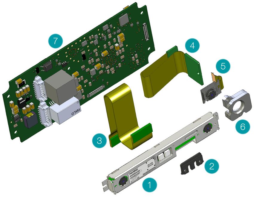
FRAMOS Depth Camera D400e Module Variant FRAMOS Depth Camera D400e module variant is a module version of the D400e series camera, providing the same functionality and connectivity without housing. The module variant aims for the easy design-in and integration into compact form factor products. The module variants have the same technical specifications as housed camera variants. 5.1 D400e Module Components FRAMOS D400e Module consist of: 1. Intel RealSense Depth Module: D415e: Intel D410 Depth Module D435e: Intel D430 Depth Module D455e: Intel D450 Depth Module 2. Depth Module Cable Bracket 3. Depth Module Interposer 4. RGB Module Interposer (D415e/D435e only) 5. RGB Module (D415e/D435e only) 6. RGB Module Cover (D415e/D435e only) 7. FRAMOS D4 Visual Processing Board Figure 7 – FRAMOS D400e Module Components Overview FRAMOS Industrial Depth Camera D400e Series - User Manual Version 1.5.0 from 2021-07-15 25 of 63
Figure 8 – Connecting Interposer Cables to FRAMOS D4 Visual Processing Board Caution: Care should be taken when connecting RGB and Depth Interposer cables to FRAMOS D4 Visual Processing Board, as the wrong connection, position or orientation, can cause permanent damage to the device. The correct cables position and orientation are shown in the Figure 8. 5.2 D400e Module Variant Connectors Pinout Molex Pico Blade Standard Connector 53398-0871 is an interface connector for the ethernet, power supply and GPIOs: J3 Ethernet Connector J6 Power and IO Connector FRAMOS Industrial Depth Camera D400e Series - User Manual Version 1.5.0 from 2021-07-15 26 of 63
5.2.1 Ethernet Connector J3

 Figure 9 – FRAMOS D4 Visual Processing Board Ethernet Connector

 J3 Pin Description
 P1 BI_DA+

 P2 BI_DA-

 P3 BI_DD+

 P4 BI_DD-

 P5 BI_DC+

 P6 BI_DC-

 P7 BI_DB+

 P8 BI_DB-
 Table 23 – J3 Pin Assignment

FRAMOS Industrial Depth Camera D400e Series - User Manual
Version 1.5.0 from 2021-07-15 27 of 63
5.2.2 Power and IO Connector J6

 Figure 10 – FRAMOS D4 Visual Processing Board Power and IO Connector

 J6 Pin Description
 DC Power supply, 12-24V DC (+/-
 P1 10%)
 P2 Power GND

 P3 Not connected

 P4 Not connected

 P5 Not connected

 P6 GND for opto-isolated I/O

 P7 Opto-isolated OUT

 P8 Opto-isolated IN
 Table 24 – J6 Pin Assignment

FRAMOS Industrial Depth Camera D400e Series - User Manual
Version 1.5.0 from 2021-07-15 28 of 63
5.3 Thermal Design Consideration
When integrating D400e Module variant in a custom design, thermal mechanical design must be
considered.

 Recommendation: A heat sink should be designed to have optimal contact with
 all elements of the PCBs backside. The back cover of the housed version can
 be used as reference design. When designed according to the
 recommendation, the D400e Module Variant can achieve the thermal conditions
 described in the "Optimum Thermal Conditions" chapter.

5.4 Mechanical Drawings

5.4.1 FRAMOS D4 Visual Processing Board

Top and side views and dimensions [mm] for the FRAMOS D4 Visual Processing Board are shown
in the image below.

 Figure 11 – FRAMOS D4 Visual Processing Board Dimensions

5.4.2 Depth Module Interposer

 Figure 12 – Depth Module Interposer Dimensions

FRAMOS Industrial Depth Camera D400e Series - User Manual
Version 1.5.0 from 2021-07-15 29 of 63
5.4.3 Depth Module Cable Bracket

 Figure 13 – D435e Depth Module Cable Bracket Dimensions

 Figure 14 – D415e Depth Module Cable Bracket Dimensions

 Figure 15 – D455e Depth Module Cable Bracket Dimensions

5.4.4 RGB Module Including Cover

 Figure 16 – RGB Module Including Cover Dimensions

5.4.5 RGB Interconnect

 Figure 17 – RGB Interconnect Dimensions

FRAMOS Industrial Depth Camera D400e Series - User Manual
Version 1.5.0 from 2021-07-15 30 of 63
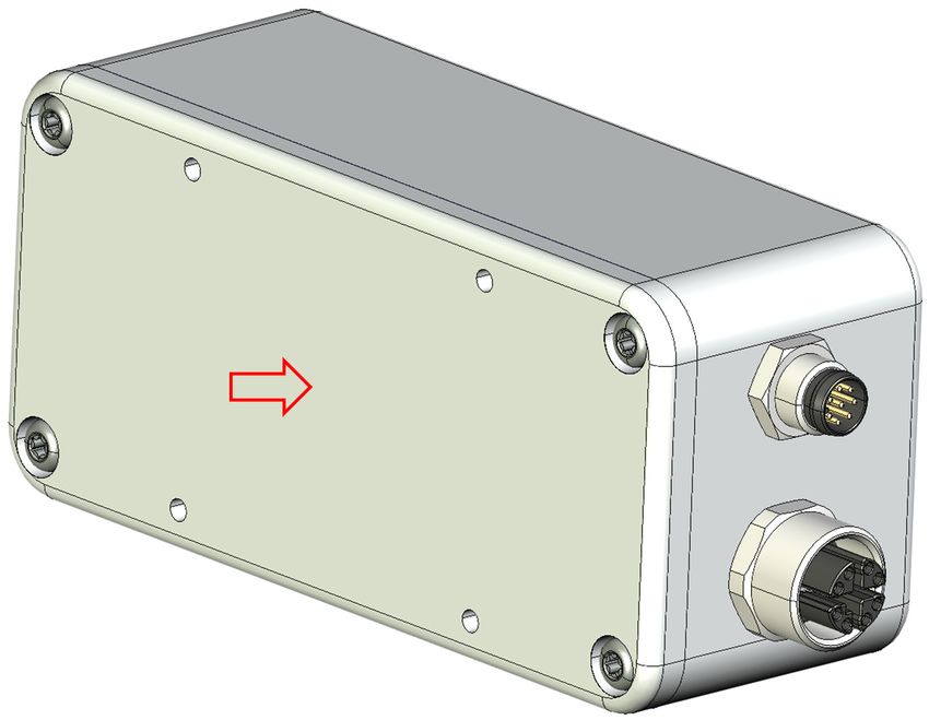
Optimum Thermal Conditions
6.1 Fundamentals of the Camera’s Heat Dissipation
The power consumption of the D400e cameras is the main determining factor for heat creation
inside the camera, which depends on the operation mode of the camera. In the case that all
available functionality of the camera (i.e. frame rates or projector intensity) is used at maximum
capacity, the power consumption and thus the heat generation increases accordingly. Aside from
the resource utilization of the camera, the power supply option also has a large effect on power
consumption. PoE (power over Ethernet) has a higher power consumption due to the uneven
efficiency of circuitry compared to the circuitry used when powering the camera via the M8
connector.
 Power Supply Option Max.
 Power via M8 7W
 Power via M12 (PoE) 8W
 Table 25 – D400e Maximum Power Consumption

Most of the power consumed by the camera is converted to heat and consequently, the camera
will generate heat that is released to the ambient via the camera’s housing.
Due to the internal structure of the camera, most heat dissipation will happen via the back side.
Therefore, this part of the camera body is intended for thermal coupling with an external dissipative
element such as a camera holder or stand. In tabletop applications, a simple heatsink element can
be used. It is recommended to use metal parts for camera mounts to assure a good thermal
conductivity on the back side of the camera body. Four threaded holes (M3 for D415e/D435e, M4
for D455e) are available on the camera back side to attach the camera to a mounting facility. It is
recommended to use thermal paste on the contact surface between the camera and the heatsink
for maximum thermal conductivity.

 Figure 18 – Hottest Part of the Camera Housing

FRAMOS Industrial Depth Camera D400e Series - User Manual
Version 1.5.0 from 2021-07-15 31 of 63
The maximum allowed operating temperature of the camera is defined as the temperature
measured on the camera housing on the back side of the case, as shown in the figure above.

 Operating Temperature Min. Max.
 Temperature of the case (measured on the back side of 0 °C 60 °C
 the camera)
 Table 26 – D400e Operating Temperature

Exceeding the maximum operating temperature defined in the table above can lead to permanent
damage of the camera. The thermal dynamic of the camera is relatively slow due to the mass of
the housing and its internal construction. Therefore, more than 1.5h of steady operation under an
unchanged ambient condition, is necessary for the camera to reach the thermal steady state.
The camera operator should be aware of the camera settings that affect power consumption
(framerate, laser usage, …), the power supply options and environmental conditions, to assure that
the camera remains in a safe temperature range at all time. Examples of using appropriate heatsinks
are discussed in the following chapter.

6.2 Operating Conditions for Different Temperatures
Depending on the ambient conditions, the camera can either operate without any additional heat
dissipation element or with an adequate heatsink attached. The allowed maximum ambient
temperatures are given for different operating modes of the camera, to indicate at which
configuration the camera can run in several application use cases.

 Use case: Description:
 Typical1 Power supply: M8, 12V
 Exposure time: 5 ms
 Framerate: 30 fps
 Laser projector power: 150 mW
 Typical2 Power supply: M12, PoE
 Exposure time: 5ms
 Framerate: 30 fps
 Laser projector power: 150mW
 Max1 Power supply: M8, 12V
 Exposure time: 30 ms
 Framerate: 30 fps
 Laser projector power: 360 mW
 Max2 Power supply: M12, PoE
 Exposure time: 30 ms
 Framerate: 30 fps
 Laser projector power: 360 mW
 Table 27 – Operating Conditions for Different Temperatures

FRAMOS Industrial Depth Camera D400e Series - User Manual
Version 1.5.0 from 2021-07-15 32 of 63
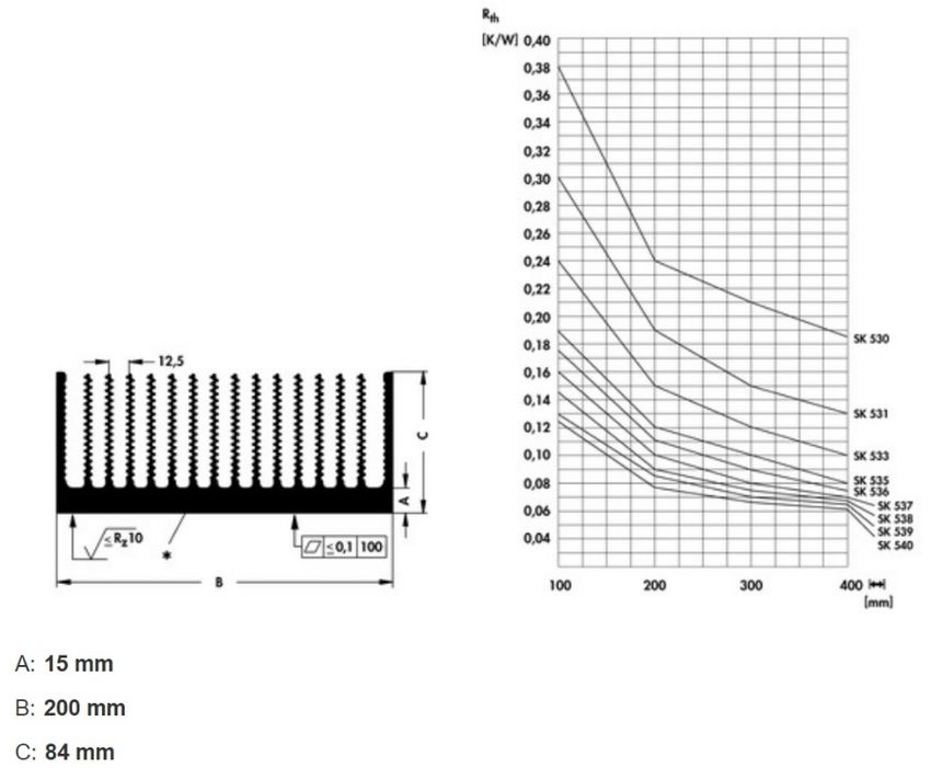
The table below lists several heat dissipation elements that can be used to keep the camera in a
safe operation mode.

 Heatsink: Description:
 H0 No heatsink attached
 H1 - passive SK 424 75 ME
 Heatsink length: 75 mm
 Thermal resistance: approx. 3.8 K/W

 H2 - passive SK 408 50 ME
 Heatsink length: 50 mm
 Thermal resistance: approx. 2.3 K/W

 H3 - passive SK 530 100 AL
 Heatsink length: 100 mm
 Thermal resistance: approx. 0.38 K/W

FRAMOS Industrial Depth Camera D400e Series - User Manual
Version 1.5.0 from 2021-07-15 33 of 63
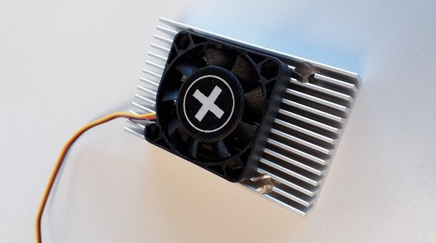
H4 - active SK 424 75 ME
 Heatsink length: 75 mm
 Cooling fan: Xilence XPF40

 Table 28 – Heat Dissipation Elements

FRAMOS Industrial Depth Camera D400e Series - User Manual
Version 1.5.0 from 2021-07-15 34 of 63
6.3 Maximum Operating Ambient Temperatures
The table below is showing maximal allowed ambient temperatures that keep the camera working
within its safe operating temperature range. These results can be used when defining a cooling
solution for a specific camera use case.
The given information is based on testing the camera in its thermal steady state using a thermal test
chamber. In the chamber, there was no airflow at all. A temperature measurement error of ±1°C is
possible.

 Operating mode Typical1 Typical2 Max1 Max2

 Cooling option

 H0 – no heatsink 32 °C 28 °C 26 °C 25 °C
 H1 – passive 37 °C 33 °C 33 °C 31 °C
 H2 – passive 45 °C 44 °C 44 °C 42 °C
 H3 – passive 53 °C 52 °C 52 °C 51 °C
 H4 – active 54 °C 53 °C 53 °C 52 °C
 Table 29 – Maximum Operating Ambient Temperatures

6.4 Summary of Operating Conditions and Temperatures
Depending on the operation mode of the camera and the applied heat dissipation elements,
ambient temperatures between 25°C and 54°C are possible. Table 29 shows that camera can
operate in normal indoor environments (up to 31°C – 37°C) with very small heatsink such as H1.
For moderately increased ambient temperatures, larger heat sinks must be used. H2 is showing
the tradeoff between heatsink size and maximal allowed ambient temperatures at 42°C – 45°C. For
very high ambient temperatures either large heatsink elements (H3) or active cooling (H4) must be
used.
Without any heatsink attached, the camera can sustain ambient temperature 25°C – 32°C,
depending on its utilization rate. Considering the fact, that in most cases the camera will be fixed
on a mount, the inherent heat dissipation will likely be better than shown in H0. Consequently, the
allowed ambient temperature will be higher than indicated in the H0 column. By choosing the
appropriate camera holder, sufficient thermal conductivity for most typical applications can be
achieved.
The specific customer application will differ from the examples shown above and every solution will
require a thermal analysis to ensure safe and reliable operation of the camera. Given information
should be used as a guideline at customers system design time.

 Recommendation: Use metal camera mount to assure optimal heat conductivity
 (avoid plastic mounts).

FRAMOS Industrial Depth Camera D400e Series - User Manual
Version 1.5.0 from 2021-07-15 35 of 63
Recommendation: In case there is a problem with overheating it is
 recommended to supply power to the camera via M8 connector rather than
 using PoE.

 Recommendation: Minimize the resource utilization (i.e. fps, exposure, projector
 intensity) of the camera, which will positively affect heat generation and longevity
 of the product.

FRAMOS Industrial Depth Camera D400e Series - User Manual
Version 1.5.0 from 2021-07-15 36 of 63
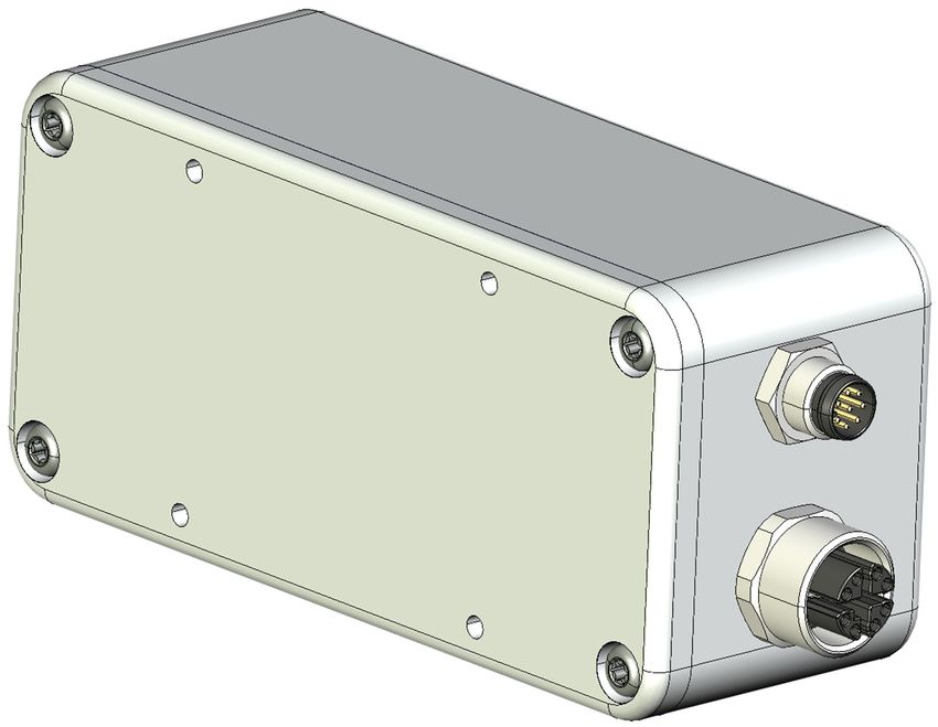
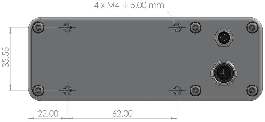
Mounting and Deployment
7.1 Camera Mounting
D400e cameras are designed to support mounting on the back side of the housing. The internal
structure of the device is designed to dissipate most of the generated heat through this part of
camera housing. Therefore, it is recommended to use a holder or stand which will ensure good
mechanical stability of the camera but also act as a thermal drain. For this purpose, metal parts with
high thermal conductivity and which are physically connected to a large part of the camera back
side, are recommended. Please avoid materials like plastic, rubber or similar materials with high
thermal resistance.
On the back side of the D415e/D435e camera body, four M3 thread holes are available for
mounting. Since the housing is made of aluminum and M3 thread holes depth is 3.2mm, care is
required when tightening the screws to avoid thread damage. Applied tightening torque should not
exceed 100 cNm for these screws.

 Figure 19 – D400e Series Camera Body Back Side
The D455e camera features four robust M4 thread holes for mounting, with stainless steel thread
inserts and maximum insertion depth of 5mm. Applied tightening torque for mounting screws should
not exceed 100 cNm, to avoid thread damage.
The camera is constructed for operation in industrial environments and can be used with moving
objects. For this purpose, it is tested and compliant according to: EN 60068-2-6, EN 60068-2-64
and EN 60068-2-27 norms. However, stronger shock and vibration can lead to damage of sensitive
optical and electronic components inside the camera. Dropping the camera or colliding it with any
surface can lead to severe damage.

FRAMOS Industrial Depth Camera D400e Series - User Manual
Version 1.5.0 from 2021-07-15 37 of 63
7.2 Application of External Cabling
The camera interface has a M8 and a M12 industrial grade connector. The M8 connector is used
for power supply and external synchronization while the M12 connector serves for data transmission
and power over Ethernet (in case the M8 connector is not used for power supply). Both are
receptacles for relatively large external cable connectors.

When connecting the camera with external cable connectors (either M8 or M12), the corresponding
camera connector nut should be held with an appropriate wrench. In the case the nut is not held
by a wrench, the respective connector could be turned together with the cable if excessive force
is applied. This should be prevented as it could cause damage to the internal camera wiring.
The FRAMOS D400e series camera is supplied with the M8 connector covered with a protective
plastic cap. The function of the protective cap is to protect the M8 connector against impurities and
moisture in the case the connector is not used, thus keeping it clean and ready for future.

 Recommendation: When attaching M8 and M12 cables to camera, connectors
 should be fixed with a tool (wrench/key) so that the connectors do not rotate
 under force.

 Recommendation: Use the protective cap on the M8 connector in the case the
 M8 connector is not used to protect it from environmental influences (exposure
 of connector pins to humidity, dust, and other particles). Note that protective cap
 does not influence the IP rating of the camera.

7.3 Cleaning Procedures
Depending on the operating environment, the camera needs to be cleaned from time to time. For
cleaning the camera housing, it is recommended to use a soft camera cleaning brush or a soft
cleaning cloth.

Using an eyeglass cleaning cloth is recommended for cleaning the camera glass window. Although
the hardness of used glass is grade 6H, special attention is required when cleaning the window to
prevent long term decreasing of optical properties. Using inadequate cleaning materials can cause
micro scratches of the camera window.
Ethyl alcohol can be used for light wiping of the entire camera housing. Using strong solvents is not
recommended and can lead to aesthetic or functional damage of the camera.

FRAMOS Industrial Depth Camera D400e Series - User Manual
Version 1.5.0 from 2021-07-15 38 of 63
You can also read