SOLSTICE SURGICAL TECHNIQUE GUIDE - Designs for Life - SPINEMarketGroup
←
→
Page content transcription
If your browser does not render page correctly, please read the page content below
SOLSTICE
                                             ®

 OCCIPITO-CERVICO-THORACIC (OCT) SYSTEM
   SURGICAL TECHNIQUE GUIDE

                                      Designs for Life.®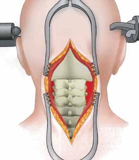
SOLSTICE
                                                                                                                               ®

                         OCCIPITO-CERVICO-THORACIC (OCT) SYSTEM
                              SURGICAL TECHNIQUE GUIDE

Introduction.......................................................................................................... 4

Features and Benefits........................................................................................ 4

Implants.................................................................................................................. 5

Standard Instruments........................................................................................ 8

Surgical Technique...........................................................................................13

Occipital Plate Surgical Technique..............................................................21

Product Information.........................................................................................26

                                                                                                                                   3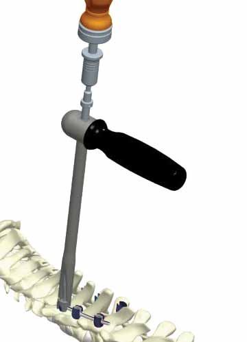
INTRODUCTION
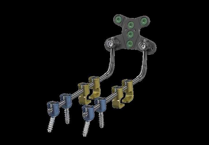
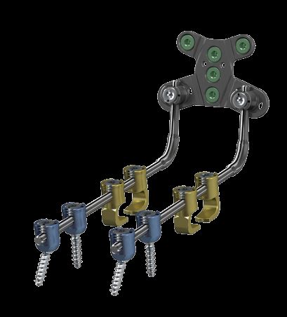
The SOLSTICE® OCT System provides rigid stabilization and promotes fusion of the posterior occipito-cervico-thoracic
regions (Occiput -T3) of the spine. The system contains easy to use implants and instruments that address simple and
complex cases and unique patient anatomies.
The SOLSTICE OCT System incorporates a number of engineered features that make the system uniquely designed to
increase the speed, ease of use, and reliability of posterior occipito-cervico-thoracic fixation of the spine.
features and benefits
The SOLSTICE® System offers the following features and benefits.
features benefits
90° Polyaxial head angulation Provides for optimal screw placement
Polyaxial “Friction head” Maintains screw head position within the surgical wound
Pre-timed Locking Cap Reduces chance of cross threading
Laser marked 3.5mm rods (straight or Pre-
Simplifies contoured rod placement
Lordosed)
3.5mm, 4.0mm, & 4.5mm Polyaxial screw
Accommodates various patient anatomies and revision surgeries
diameter
10mm - 20mm screws in 2mm increments
Full spectrum of Polyaxial screw lengths
25mm - 50mm screws in 5mm increments
Reduced inner diameter screw tip Allows for easier insertion into the bone
Low profile system Reduced construct height reduces soft tissue irritation
Facilitates easy rod placement from the occipital plate to the
2 points of translation/rotation
Cervico-Thoracic region.
Important: All referenced implants and instruments are designed and tested for use only with the Solstice OCT
System. This surgical technique guide sets forth detailed, recommended procedures for using the Solstice OCT
implants and instruments. It offers guidance that you should heed but, as with any such technical guide, each
surgeon must consider the particular needs of each patient and make appropriate adjustments when required.
Note: This manual is intended as a guide only. There are multiple techniques for the implantation of spinal fixation
systems and, as with any surgical procedure, the surgeon should be trained and thoroughly familiar with the implant
system components before proceeding.
4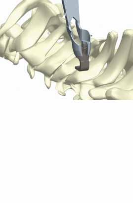
system configuration - polyaxial screws
catalog number               measurement                      description                                   qty/set

9035-10                      3.5mm x 10mm                     SOLSTICE Poly Screw Assembly                    12
9035-12                      3.5mm x 12mm                     SOLSTICE Poly Screw Assembly                    12
9035-14                      3.5mm x 14mm                     SOLSTICE Poly Screw Assembly                    12
9035-16                      3.5mm x 16mm                     SOLSTICE Poly Screw Assembly                    12
9035-18                      3.5mm x 18mm                     SOLSTICE Poly Screw Assembly                     6
9035-20                      3.5mm x 20mm                     SOLSTICE Poly Screw Assembly                     6
9035-25*                     3.5mm x 25mm                     SOLSTICE Poly Screw Assembly                     6
9035-30*                     3.5mm x 30mm                     SOLSTICE Poly Screw Assembly                     6
9035-35*                     3.5mm x 35mm                     SOLSTICE Poly Screw Assembly                     6
9035-40*                     3.5mm x 40mm                     SOLSTICE Poly Screw Assembly                     6
9035-45*                     3.5mm x 45mm                     SOLSTICE Poly Screw Assembly                     6
9035-50*                     3.5mm x 50mm                     SOLSTICE Poly Screw Assembly                     6
9040-10                      4.0mm x 10mm                     SOLSTICE Poly Screw Assembly                     6
9040-12                      4.0mm x 12mm                     SOLSTICE Poly Screw Assembly                     6
9040-14                      4.0mm x 14mm                     SOLSTICE Poly Screw Assembly                     6
9040-16                      4.0mm x 16mm                     SOLSTICE Poly Screw Assembly                     6
9040-18                      4.0mm x 18mm                     SOLSTICE Poly Screw Assembly                     6
9040-20                      4.0mm x 20mm                     SOLSTICE Poly Screw Assembly                     6
9040-25*                     4.0mm x 25mm                     SOLSTICE Poly Screw Assembly                     6
9040-30*                     4.0mm x 30mm                     SOLSTICE Poly Screw Assembly                     6
9040-35*                     4.0mm x 35mm                     SOLSTICE Poly Screw Assembly                     6
9040-40*                     4.0mm x 40mm                     SOLSTICE Poly Screw Assembly                     6
9040-45*                     4.0mm x 45mm                     SOLSTICE Poly Screw Assembly                     6
9040-50*                     4.0mm x 50mm                     SOLSTICE Poly Screw Assembly                     6
9045-10*                     4.5mm x 10mm                     SOLSTICE Poly Screw Assembly                     6
9045-12*                     4.5mm x 12mm                     SOLSTICE Poly Screw Assembly                     6
9045-14*                     4.5mm x 14mm                     SOLSTICE Poly Screw Assembly                     6
9045-16*                     4.5mm x 16mm                     SOLSTICE Poly Screw Assembly                     6
9045-18*                     4.5mm x 18mm                     SOLSTICE Poly Screw Assembly                     6
9045-20*                     4.5mm x 20mm                     SOLSTICE Poly Screw Assembly                     6
9045-25*                     4.5mm x 25mm                     SOLSTICE Poly Screw Assembly                     6
9045-30*                     4.5mm x 30mm                     SOLSTICE Poly Screw Assembly                     6
9045-35*                     4.5mm x 35mm                     SOLSTICE Poly Screw Assembly                     6
9045-40*                     4.5mm x 40mm                     SOLSTICE Poly Screw Assembly                     6
9045-45*                     4.5mm x 45mm                     SOLSTICE Poly Screw Assembly                     6
9045-50*                     4.5mm x 50mm                     SOLSTICE Poly Screw Assembly                     6

system configuration - locking cap
catalog number                        description                                                           qty/set

900-003                               SOLSTICE Locking Cap Assembly                                           12

             * Items are special order. Please contact customer service at 847.884.6117 for availability.

                                                                                                                      5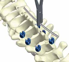
system configuration - hooks
    catalog number               measurement                      description                                   qty/set

    900-045                      4.5mm                            SOLSTICE Inline Hook                             4
    900-060                      6.0mm                            SOLSTICE Inline Hook                             4

    system configuration - rods
    catalog number               measurement                      description                                   qty/set

    3350-040*                    3.5mm x 40mm                     Rod                                              4
    3350-080                     3.5mm x 80mm                     Rod                                              4
    3350-120                     3.5mm x 120mm                    Rod                                              4
    3350-240                     3.5mm x 240mm                    Rod                                              4
    3551-200*                    400mm (200/200)                  Transitional Rod                                 4
    3551-300*                    600mm (300/300)                  Transitional Rod                                 4
    4350-080*                    3.5mm x 80mm                     Pre-Lordosed Rod                                 4

    system configuration - occipital set - occipital bone screws
    catalog number                measurement                     description                                   qty/set

    9250-06                       5.0mm x 6mm                     SOLSTICE Occipital Bone Screw                    4
    9250-07                       5.0mm x 7mm                     SOLSTICE Occipital Bone Screw                    4
    9250-08                       5.0mm x 8mm                     SOLSTICE Occipital Bone Screw                    4
    9250-09                       5.0mm x 9mm                     SOLSTICE Occipital Bone Screw                    4
    9250-10                       5.0mm x 10mm                    SOLSTICE Occipital Bone Screw                    4
    9250-11                       5.0mm x 11mm                    SOLSTICE Occipital Bone Screw                    4
    9250-12                       5.0mm x 12mm                    SOLSTICE Occipital Bone Screw                    4
    9250-13                       5.0mm x 13mm                    SOLSTICE Occipital Bone Screw                    4
    9250-14                       5.0mm x 14mm                    SOLSTICE Occipital Bone Screw                    4
    9250-15                       5.0mm x 15mm                    SOLSTICE Occipital Bone Screw                    2
    9250-16                       5.0mm x 16mm                    SOLSTICE Occipital Bone Screw                    2
    9250-17*                      5.0mm x 17mm                    SOLSTICE Occipital Bone Screw                    4
    9250-18*                      5.0mm x 18mm                    SOLSTICE Occipital Bone Screw                    4
    9255-06                       5.5mm x 6mm                     SOLSTICE Occipital Bone Screw                    4
    9255-07                       5.5mm x 7mm                     SOLSTICE Occipital Bone Screw                    4
    9255-08                       5.5mm x 8mm                     SOLSTICE Occipital Bone Screw                    4
    9255-09                       5.5mm x 9mm                     SOLSTICE Occipital Bone Screw                    4
    9255-10                       5.5mm x 10mm                    SOLSTICE Occipital Bone Screw                    4
    9255-11                       5.5mm x 11mm                    SOLSTICE Occipital Bone Screw                    4
    9255-12                       5.5mm x 12mm                    SOLSTICE Occipital Bone Screw                    4
    9255-13                       5.5mm x 13mm                    SOLSTICE Occipital Bone Screw                    4
    9255-14                       5.5mm x 14mm                    SOLSTICE Occipital Bone Screw                    4
    9255-15                       5.5mm x 15mm                    SOLSTICE Occipital Bone Screw                    2
    9255-16                       5.5mm x 16mm                    SOLSTICE Occipital Bone Screw                    2
    9255-17*                      5.5mm x 17mm                    SOLSTICE Occipital Bone Screw                    4
    9255-18*                      5.5mm x 18mm                    SOLSTICE Occipital Bone Screw                    4

                 * Items are special order. Please contact customer service at 847.884.6117 for availability.

6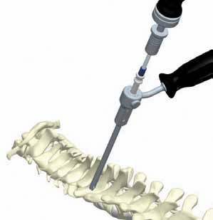
system configuration - occipital set - smooth shaft screws
catalog number               measurement                      description                                   qty/set

9135-20                      3.5 x 20mm                       SOLSTICE Smooth Shaft Assembly                   4
9135-22                      3.5 x 22mm                       SOLSTICE Smooth Shaft Assembly                   4
9135-24                      3.5 x 24mm                       SOLSTICE Smooth Shaft Assembly                   4
9135-26                      3.5 x 26mm                       SOLSTICE Smooth Shaft Assembly                   4
9135-28                      3.5 x 28mm                       SOLSTICE Smooth Shaft Assembly                   4
9135-30                      3.5 x 30mm                       SOLSTICE Smooth Shaft Assembly                   4
9140-20                      4.0 x 20mm                       SOLSTICE Smooth Shaft Assembly                   4
9140-22                      4.0 x 22mm                       SOLSTICE Smooth Shaft Assembly                   4
9140-24                      4.0 x 24mm                       SOLSTICE Smooth Shaft Assembly                   4
9140-26                      4.0 x 26mm                       SOLSTICE Smooth Shaft Assembly                   4
9140-28                      4.0 x 28mm                       SOLSTICE Smooth Shaft Assembly                   4
9140-30                      4.0 x 30mm                       SOLSTICE Smooth Shaft Assembly                   4

system configuration - occipital set - occipital plates
catalog number               measurement                      description                                   qty/set

9200-10*                     21mm-32mm                        SOLSTICE Occipital Plate                         2
9200-11                      25mm-36mm                        SOLSTICE Occipital Plate Small                   2
9200-12                      29mm-40mm                        SOLSTICE Occipital Plate Medium                  2
9200-13                      36mm-47mm                        SOLSTICE Occipital Plate Large                   2

system configuration - occipital set - occipital rods
catalog number     measurement                                description                                   qty/set

9350-170           170mm                                      Pre-Bent Occipital Rod 110 Degrees               4

             * Items are special order. Please contact customer service at 847.884.6117 for availability.
                                                                                                                      7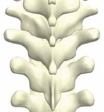
STANDARD INSTRUMENTS - SOLSTICE
    Various instruments are available for use with the Solstice Occipito-Cervico-Thoracic System to facilitate implantation.

     113-112             Mini Axial Ratcheting Handle w/ A/O
                         Quick Couple

                                                                             117-922              Kerrison Rod Reducer, Solstice

     113-161             20 in. lbs. Torque Limiting Driver w/ A/O
                         Quick Couple
                                                                             117-892              Rod Pusher/Rod Holder

     117-894             Solstice Hook Impactor

                                                                             117-928             3.5mm/4.5mm Rod Bender, Solstice

     117-895             Solstice Hook Holder

                                                                             117-941              Polyaxial Screw Inserter, Solstice

     117-896             Head Positioner/Hook Inserter

8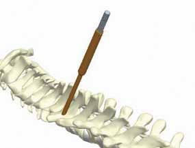
STANDARD INSTRUMENTS - SOLSTICE

                                                        117-961      Awl

117-953      Adjustable Drill Guide
117-953-1    with Depth Gauge

                                                          117-962      Counter Torque Tube, Solstice
117-955      3.5mm Drill (Single Use Only), Solstice

117-956      4.0mm Drill (Single Use Only), Solstice

                                                       117-963      Lenke Bone Probe Straight, Solstice

117-958      Solstice Tap 3.5mm

                                                        117-964       Sounding Probe, Solstice

117-959      Solstice Tap 4.0mm

                                                        117-965      Depth Gauge

                                                                                                          9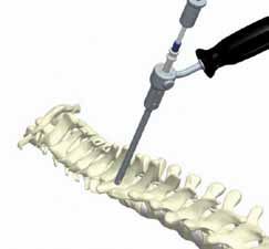
STANDARD INSTRUMENTS - SOLSTICE

     117-966      Rod Holder/Inserter, Solstice

                                                           117-970    Compressor -Around the Rod, Solstice

     117-967      Locking Cap Final Torque Driver Shaft

                                                          117-971    Distractor -Around the Rod, Solstice

     117-968      Switching Stick/Locking Cap Inserter

                                                           117-973    Rod Template, Solstice

     117-969      3.5mm insitu Rod Cutter, Solstice

10
STANDARD INSTRUMENTS - SOLSTICE OCCIPITAL SET
113-106 Fixation Pin Inserter 117-983 Fixation Pin
(Large Hole)
117-979 5.0mm Occipital Drill
(Single Use Only)
113-169 Spin Cap Handle w/ AO
Quick Couple
117-980 5.0mm Flexible Occipital Drill
117-981 5.0mm Occipital Tap 117-986 Occipital Adjustable Drill Guide
117-986-1 with Depth Gauge
117-982 5.0mm Flexible Occipital Tap
117-987 Occipital Plate Holder
117-996 3.5mm Cervical Drill (Smooth Shaft)
117-997 4.0mm Cervical Drill (Smooth Shaft)
11STANDARD INSTRUMENTS - SOLSTICE OCCIPITAL SET
117-988 Flexible Instrument Holder 117-991 Occipital Plate Bending Pliers
117-989 Occipital Screw Driver
117-992 Occipital Tube Benders
117-990 Flexible Occipital Screw Driver
117-993 Occipital Counter Torque Tube
117-978 Occipital Plate Bender
121. Preoperative Planning and
Patient Positioning
Preoperative planning is critical in the preparation for spinal
surgery. Due to the anatomic variability of each patient, the
surgeon must have the range of necessary images in order to be
equipped to plan the operation appropriately. Carefully place the
patient in the prone position with head and neck held securely
in proper alignment.
2. Exposure
A midline vertical skin incision can be made (as necessary)
extending from the occipital protuberance past the spinous
process of the seventh cervical vertebra (prominent vertebra).
(Figure 1)
The nuchal ligament is divided in the midline and incised as far
as the tips of the spinous processes.
The deep muscle layer is stripped off the spinous processes close
Figure 1
to the bone with the aid of electrocautery.
Subperiosteal dissection is carried to the lateral boundary of the
articular masses.
3. Placement of Laminar Hooks
There are two hook options: 4.5mm and 6.0mm. Determine
the appropriate hook size based on the thickness of the lamina.
Prepare attachment point for the hook using a standard
preparation technique.
Place the hook in the desired location utilizing the .
Hook Holder. The Hook Impactor may be used to
facilitate placement of the hook. (Figure 3)
See Steps 7-13 for rod placement and final tightening
instructions.
4.5 6.0
A. Throat Height 4.5mm
B. Blade Length 10.4mm
A C C. Throat Height 6.0mm
D. Blade Length 10.4mm
B D
Indications for Use of Laminar Hooks Figure 3
Solstice Laminar Hooks are FDA cleared for use throughout the
cervical and upper thoracic (C3-T3) spine.
134. Polyaxial Screw Preparation
Following preparation of the relevant posterior spinal elements
by removing all soft tissue and decorticating the facets and
laminae, determine and mark the ideal entry point for all
Polyaxial Screws with a burr or marking pen. (Figure 4)
Figure 4
Once the entry point is determined, a pilot hole .
may be prepared with the Awl w/ Stop. This will help
to prevent displacement of the Drill bit during initial
insertion. The Awl w/ Stop has a 10mm depth stop
distance to prevent over-plunging. (Figure 4a)
.
Figure 4a
The Adjustable Drill Guide allows for a single drill
bit to be used for preparation of variable depths. To set the
Adjustable Drill Guide depth, depress the adjustment
button and slide depth stop to desired depth as indicated on the
calibrated depth stop. The depth is defined by the position of the
Drill Guide Stop relative to the scale of the Adjustable Drill
Guide. (Figure 4b)
To drill a hole, place the appropriate Drill into the barrel of
the Adjustable Drill Guide and apply downward pressure
while turning the Drill clockwise until the step of the Drill 8
10
shaft contacts the guide. (Figure 4c) The Drill bit depth shown 12
in the inset of Figure 4c will match the depth assigned to The 14
16
Adjustable Drill Guide Depth Gauge. 18
20
22
Figure 4b
Each size drill bit has a color ring that corresponds to the color of
each Polyaxial Screw head diameter.
3.5mm = Blue
4.0mm = Green
*4.5mm = Magenta
* Special order, please contact customer service for availability.
Indications for Use of Polyaxial Screws
Solstice Polyaxial Screws are FDA cleared for .
use in the upper thoracic spine (T1-T3).
Figure 4c
14If the surgeon prefers, a path may be prepared with the
Straight Thoracic Lenke Bone Probe. The probe
should be in contact with the bone at all times. By gently
following the path of least resistance, the Straight Thoracic
Lenke Bone Probe is inserted without violating the walls of the
pedicle. Re-evaluate the entry point and trajectory if significant
resistance is encountered.
The Straight Thoracic Lenke Bone Probe is calibrated and
laser etched in 5mm increments to help indicate the depth to
which the probe is inserted as well as to help determine proper
screw length. (Figure 4d)
Figure 4d
Verify Pathway
Check the prepared pathway with the Sounding Probe to
verify that all walls of the pedicle are intact and cancellous bone
is felt at the distal end of the path. The Sounding Probe is
calibrated and laser etched in 5mm increments to help indicate
the depth to which the probe is inserted as well as to help
determine proper screw length. (Figure 4e)
Figure 4e
Measure Pathway
he depth of the pilot hole can be confirmed using
T
the Depth Gauge. (Figure 4f)
NOTE: The Depth Gauge reflects the actual screw thread
length, therefore select the same screw length as indicated
by gauge, e.g., 10mm Depth Gauge reading, select 10mm
Polyaxial Screw.
Figure 4f
15Tapping Technique (optional)
Tapping is optional since screws have a self-tapping .
starter tip. Tap diameters are a 1:1 ratio with screw
outer diameters. The appropriate Tap may be used to
prepare the pedicle canal when the surgeon is having .
difficulty starting the self-tapping screw.
To tap, apply downward pressure while turning the Tap
clockwise until desired number of threads are created within .
the pedicle pathway. (Figure 4g) The taps are laser etched in
2mm increments to help determine proper screw length.
Figure 4g
Each size Tap has a color sleeve that corresponds to
the color of each Polyaxial Screw head diameter.
3.5mm = Blue
4.0mm = Green
*4.5mm = Magenta
* Special order, please contact customer service for availability.
.
With the pedicle pathways prepared and the proper .
screw length and diameter determined, the screw is .
prepared for insertion.
5. Verify Screw Diameter
Each Polyaxial Screw head is color coded by diameter
matching the diameters of the Drills and Taps.
3.5mm = Blue
4.0mm = Green
*
4.5mm = Magenta
Special order, please contact
*
customer service for availability.
Verify Screw Length
Figure 5
The screw length may be verified by placing the screw in the
screw-sizing slot. Place the screw in the slot making sure the
screw seat is flush with the top of the screw-sizing slot. Verify the
length by using the length indicator located on the side of the
screw sizing slot. (Figure 5)
166. Polyaxial Screw Insertion
Lock
Place the tip of the Polyaxial Screw Inserter into the screw
head. Push the inserter shaft downward and turn knurled knob
clockwise to engage the screw head. During this attachment
confirm that the screw is aligned with the inserter shaft. .
(Figure 6)
Unlock
Pull the Polyaxial Screw Inserter shaft upward and turn
knurled knob counterclockwise to disengage the screw head
from the Inserter. .
(Figure 6a)
Figure 6 Figure 6a
Bone Insertion
To insert the screw into the pedicle, apply gentle downward
force to the Polyaxial Screw Inserter and rotate the Inserter
clockwise. (Figure 6b)
. Figure 6b
The Head Positioner / Hook Inserter may be used to align
the Polyaxial Screw heads prior to rod placement. (Figure 6c)
Figure 6c
IP: If minor screw height adjustment is needed, the Locking
T
Cap Final Torque Driver Shaft may be used. (Figure 6d)
Insert all remaining Polyaxial Screws. Adjust the height of the
screw to allow a contoured rod to seat completely.
Figure 6d
177. Determine Spinal Curve Configuration
rior to rod insertion, verify the cervical and/or thoracic
P
configuration of the spine. Place the Rod Template into the
screw/hook seat(s) and mold the template by bending it to fit.
Remove the Rod Template and choose the appropriate length
pre-cut rod. Bend the rod (if necessary) using the Rod Bender
to match the Rod Template.
The Rod Template is calibrated and etched in 10mm
Figure 7
increments to help determine proper rod length. (Figure 7)
NOTE: Do not implant Rod Template.
8. Rod Cutting
he rod length may be altered using the In Situ Rod Cutter.
T
Place rod in circular opening and squeeze handles. (Figure 8)
For in situ rod cutting, place rod in between distal tips and
squeeze handles. Use forceps to prevent loss of cut segment .
in situ.
Figure 8
.
9. Rod Contouring
The rod may be contoured using the Rod Bender. Place the rod
on the appropriate side of the Rod Bender and squeeze the
handles. (Figures 9 and 9a)
Insert
Once the rod is bent to the desired contour, the . Figure 9 Figure 9a
Rod Holder/Inserter may be used to place the rod
into the screw/hook. (Figure 9b) If the rod is not
firmly placed in the screw/hook, follow the Rod .
Reduction technique, Step 11.
NOTE: Rods are laser marked to simplify rod placement in situ.
Figure 9b
1810. Locking Cap Insertion
Attach
Attach the Locking Cap to the tip of the Switching Stick/
Locking Cap Inserter and insert the Locking Cap into the
screw/hook. (Figure 10)
Position
If the laser etch marks are not lined up, turn the Locking Cap
counterclockwise until the timing marks on the Locking Cap
and screw/hook line up. In this position, the threads are .
pre-timed to align automatically and thereby minimize the
chance of cross threading. (Figure 10a) Figure 10
Tighten
Turn the Locking Cap clockwise to provisionally tighten the
Locking Cap down into the screw/hook. Do not over tighten.
In the event that physical assistance is required to hold the
rod down while tightening the Locking Cap, follow the rod
reduction technique, Step 11.
Extra caution is advised when:
• The rod is not horizontally placed into the screw/hook
• The rod is high in the screw/hook
• An acute convex or concave bend is contoured into the rod
near the screw-rod interface Figure 10a
Optional Locking Cap Insertion Technique
Attach
Place Counter Torque Tube over the screw/hook head. Attach
the Locking Cap on the tip of the Switching Stick / Locking
Cap Inserter and insert the Locking Cap into the Counter
Torque Tube, using it as your guide for accurate screw
placement. (Figure 10b)
Position
When using the Counter Torque Tube, the threads are
automatically aligned to minimize the chance of cross threading.
Tighten Figure 10b
Provisionally tighten the Locking Cap down into the screw/
hook. Do not over tighten.
1911. Rod Reduction
Persuasion
Use the Rod Pusher or Kerrison Rod Reducer when
additional physical assistance is required to ease the rod .
to the screw/hook. Both instruments push the rod .
into the screw/hook and allow for simultaneous .
insertion of the Locking Cap.
Figure 11
Kerrison Rod Reducer
Engage the Kerrison Rod Reducer with the external slots on
the screw/hook. Squeeze the handle to introduce the rod into
the screw/hook. (Figures 11-11b)
Attach the Locking Cap to the Switching Stick / Locking
Cap Inserter. Insert the Locking Cap through the distal tip of
the Kerrison Rod Reducer, into the screw/hook.
Provisionally tighten the Locking Cap.
Disengage the Kerrison Rod Reducer from the screw/hook Figure 11a Figure 11b
and repeat as necessary.
NOTE: The Kerrison Rod Reducer generates a great amount
of force. Be cautious not to exert too much pressure. This may
lead to implant or bone failure.
Rod Pusher
Place the slots of the Rod Pusher onto the rod while aligned
with the screw/hook. (Figure 11c)
Attach the Locking Cap to the Switching Stick / Locking
Cap Inserter. Insert the Locking Cap through the Rod
Pusher, into the screw/hook.
Provisionally tighten the Locking Cap.
Figure 11c
12. Distraction / Compression
Loosen the Locking Cap of the level to be adjusted.
Use the Distractor - Around the Rod (Figure 12) to achieve
distraction or the Compressor - Around the Rod (Figure 12a)
to achieve compression.
Tighten Locking Cap after distraction/compression is achieved.
Repeat for each segment as required.
Figure 12 Figure 12a
2013. Final Tightening
Attach the Locking Cap Final Torque Driver Shaft to the
20 in-lbs. Torque Limiting Driver w/ AO Quick Couple.
NOTE: The 20 in-lbs. Torque Limiting Driver w/ AO Quick
Couple Handle is orange. (Figure 13)
Place the Counter Torque Tube over the screw/hook seat.
Insert the Locking Cap Final Torque Driver Shaft
and Torque Limiting Driver Handle into the Counter
Torque Tube.
Firmly hold the 20 in-lbs. Torque Limiting Driver w/ AO
Quick Couple Handle and perform final tightening of the
Locking Cap until the 20 in-lbs. Torque Limiting Driver w/
AO Quick Couple “clicks”.
14. Closure
Wound closure is performed in the customary manner.
Revision/Implant Removal (If Required)
All implants can be removed by performing the insertion steps .
in reverse. Figure 13
Occipital Plate Technique
1. Occipital Plate Selection
Select the plate size to best fit the occiput. The Occipital .
Plate is available in three sizes, maximizing versatility in .
the medial-lateral position of the rods.
Place the occipital plate with the Plate Holder below
the exterior occipital protuberance and below the superior
nuchal lines. (Figure 1)
Small 25-36mm (width)
Medium 29-40mm (width) Figure 1
Large 36-47mm (width)
212. Occipital Plate Contouring Bend Zones
ach occipital plate may be contoured to fit the patient’s
E
anatomy. The contouring should only be performed in the .
bend zones. (Figure 2) Use caution to not over bend the plate.
Bend Zones
Figure 2
o bend, place the selected occipital plate securely in the
T
Occipital Plate Bender and gently bend to achieve desired
radius. (Figure 2a)
The Occipital Plate Bending Pliers may also be utilized.
Figure 2a
3. Temporary Occipital Plate Holding Pin Insertion
emporary Fixation Pins can be used to fixate the plate to the
T
occiput.
Utilizing the Fixation Pin Driver, drive the Occipital Plate
Holding Pin (Large Hole) into the occiput by placing the pin
through the bone screw holes. (Figure 3)
The Temporary Fixation Pin has a self-drilling tip to allow the pin
to be placed without additional hole preparation.
Figure 3
4. Occipital Plate Fixation
S tandard or flexible instruments may be utilized for Occipital
plate fixation.
Flexible Drill
Attach the Flexible Instrument Holder to the 5.0mm
Flexible Occipital Drill to use as a guide. (Figure 4) The
Flexible Occipital Drill is laser etched in 2mm increments
to help determine proper screw length.
Figure 4
22Flexible Tap
Attach the Flexible Instrument Holder to the 5.0mm
Flexible Occipital Tap to use as a guide. (Figure 4a)
The Flexible Occipital Tap is laser etched in 2mm
increments to help determine proper screw length.
Figure 4a
Drill
To set the Occipital Adjustable Drill Guide depth, depress
the adjustment button and slide depth stop to desired depth as
indicated on the calibrated depth stop. The depth is defined by
the position of the Drill Guide Stop relative to the scale of the
Occipital Adjustable Drill Guide. (Figure 4b)
Insert the Occipital Adjustable Drill Guide into the desired
hole in the plate. (Figure 4b)
Attach the 5.0mm Occipital Drill securely into the Spin Cap
Handle w/ AO Quick Couple. Insert the 5.0mm Occipital
Figure 4b
Drill through the Occipital Adjustable Drill Guide and drill
to the appropriate depth. (Figure 4c)
A positive stop on the drill will prevent over-drilling.
Intraoperative imaging should be used to confirm appropriate
drill depth.
Figure 4c
Tap
Attach the 5.0mm Occipital Tap securely into the Spin Cap
Handle w/ AO Quick Couple and tap to the appropriate
depth. (Figure 4d) The 5.0mm Occipital Tap is laser etched in
2mm increments to help determine proper screw length.
Figure 4d
235. Occipital Bone Screw Insertion
Use the Occipital Screw Driver or the Flexible Occipital
Screw Driver in conjunction with the Flexible Instrument
Holder and insert the appropriate length occipital bone screw
into the prepared hole. (Figure 5)
Repeat drill and tap occipital bone screw placement for
remaining occipital bone screws. (Figure 5a)
Confirm screw placement with intraoperative imaging.
Figure 5
Figure 5a
6. Occipital Rod Placement
Determine the appropriate contour and length of the occipital
rod with the Rod Template. Once the length is determined, cut
the occipital rod to the desired length.
Place the rod into the saddle of the occipital plate. (Figure 6)
For rod cutting, contouring and insertion, refer to Steps 8 and 9.
Figure 6
7. Locking Cap Placement
Use the Switching Stick/Locking Cap Inserter to position
and tighten the Locking Cap on the occipital plate. (Figure 7)
Prior to initial insertion, ensure the laser etch marks on both the
locking cap and screw assembly line up. This will minimize the
chance of cross threading. (Figure 7a)
All Locking Caps should be inserted prior to final tightening.
Figure 7
Figure 7a
248. Final Tightening
Attach the Locking Cap Final Torque Driver Shaft
to the 20in-lbs. Axial Torque Limiting Driver w/ AO
Quick Couple.
NOTE: The 20in-lbs. Axial Torque Limiting Driver w/
AO Quick Couple Handle is orange.
Place the Occipital Counter Torque Tube over the
screw head.
Insert the Locking Cap Final Torque Driver Shaft and Figure 8
20in-lbs. Axial Torque Limiting Driver w/ AO Quick
Couple into the Occipital Counter Torque Tube.
(Figure 8)
Firmly hold the 20in-lbs. Axial Torque Limiting Driver
w/ AO Quick Couple and perform final tightening of the
Locking Cap until the 20in-lbs. Axial Torque Limiting
Driver w/ AO Quick Couple “clicks”.
Repeat on remaining occipital screw head. (Figure 8a)
9. Closure
Figure 8a
Wound Closure is performed in the customary manner.
Removal (If Required)
All implants can be removed by performing the insertion steps in
reverse.
25Important Information on the SOLSTICE OCT System 21. Non-union (or pseudarthrosis). Delayed union. Mal-union.
22. Cessation of any potential growth of the operated portion of the spine. Loss of spinal
Description:
mobility or function.
The SOLSTICE OCT System is a temporary, titanium alloy (6AL-4V-ELI per ASTM F 136), 23. Inability to perform the activities of daily living.
multiple component system comprised of a variety of non-sterile, single use implantable 24. Paralysis
components. The system consists of an assortment of occipital plates, occipital bone screws, 25. Death
polyaxial screws, hooks, rods, and locking breakaways. Note: Additional surgery may be necessary to correct some of these anticipated adverse
events
Indications, Contraindications, and Possible Adverse Effects.
Warnings and Precautions:
Indications: A successful result is not always achieved in every surgical case. This fact is especially true
When intended to promote fusion of the cervical spine and occipito-cervico-thoracic junction in spinal surgery where many extenuating circumstances may compromise the results. The
(Occiput – T3), the SOLSTICE OCT System, when properly used, is intended for: Degenerative SOLSTICE OCT System is only a temporary implant used for the correction and stabilization of
Disc Disease (as defined by neck pain of discogenic origin with degeneration of the disc the spine. This system is intended to be used to augment the development of a spinal fusion
confirmed by history and radiographic studies); spondylolisthesis; spinal stenosis; fracture/ by providing temporary stabilization. This device is not intended to be the sole means of spinal
dislocation; Atlanto/axial fracture with instability; occipitocervical dislocation; revision of support. Bone grafting must be part of the spinal fusion procedure in which the SOLSTICE
previous cervical spine surgery; OCT System is utilized. Use of this product without a bone graft or in cases that develop into
and tumors. a non-union will not be successful. This spinal implant cannot withstand body loads without
When used with occipital plate, the bone screws are limited to occipital fixation only. The bone the support of bone. In this event, bending, loosening, disassembly and/or breakage of the
screws are not intended to be used in the cervical spine. device(s) will eventually occur. Preoperative planning and operating procedures, including
knowledge of surgical techniques, proper reduction, and proper selection and placement of
The use of polyaxial screws is limited to placement in T1-T3 in treating thoracic conditions only. the implant are important considerations in the successful utilization of the SOLSTICE OCT
They are not intended to be placed in the cervical spine. System by the surgeon. Further, the proper selection and compliance of the patient will greatly
The hooks and rods are also intended to provide stabilization to promote fusion following affect the results. Patients who smoke have been shown to have an increased incidence of non-
reduction of fracture/dislocation or trauma in the cervical/upper thoracic (C1-T3) spine. unions. These patients should be advised of this fact and warned of this consequence. Obese,
malnourished, and/or alcohol and/or other drug abuse patients are also not good candidates
Contraindications: for spine fusion. Patients with poor muscle and bone quality and/or nerve paralysis are also not
Contraindications include, but are not limited to: good candidates for spine fusion.
1. Infection, local to the operative site.
2. Signs of local inflammation. PHYSICIAN NOTE: Although the physician is the learned intermediary between the
3. Fever or leukocytosis. company and the patient, the indications, contraindications, warnings and precautions
4. Morbid obesity. given in this document must be conveyed to the patient.
5. Pregnancy. CAUTION: FEDERAL (USA) LAW RESTRICTS THESE DEVICES TO SALE BY OR ON THE
6. Mental illness, alcoholism, drug abuse. ORDER OF A PHYSICIAN.
7. Any medical or surgical condition which would preclude the potential benefit of spinal
implant surgery, such as the elevation of sedimentation rate unexplained by other diseases, Other preoperative, intraoperative, and postoperative warnings are as follows:
elevation of white blood count (WBC), or a marked left shift in the WBC differential count. Implant Selection:
8. Rapid joint disease, bone absorption, osteopenia, and/or osteoporosis. Osteoporosis is a The selection of the proper size, shape and design of the implant for each patient is crucial to
relative contraindication since this condition may limit the degree of obtainable correction, the the success of the procedure. Metallic surgical implants are subject to repeated stresses in use,
amount of mechanical fixation, and/or the quality of the bone graft. and their strength is limited by the need to adapt the design to the size and shape of human
9. Suspected or documented metal allergy or intolerance. bones. Unless great care is taken in patient selection, proper placement of the implant, and
10. Any case not needing a bone graft and fusion or where fracture healing is not required. postoperative management to minimize stresses on the implant, such stresses may cause
11. Any case requiring the mixing of metals from different components. metal fatigue and consequent breakage, bending or loosening of the device before the healing
12. Any patient having inadequate tissue coverage over the operative site or where there is process is complete, which may result in further injury or the need to remove the device
inadequate bone stock, bone quality, or anatomical definition. prematurely.
13. Any condition that totally precludes the possibility of fusion, i.e. cancer, kidney dialysis
14. Any case not described in the Indications. Preoperative:
15. Any patient unwilling to cooperate with the post-operative instructions. 1. Only patients that meet the criteria described in the indications should be selected.
16. Any time implant utilization would interfere with anatomical structures or expected 2. Patient conditions and/or predispositions such as those addressed in the aforementioned
physiological performance contraindications should be avoided.
3. Care should be used in the handling and storage of the implant components. The implants
should not be scratched or otherwise damaged. Implants and instruments should be protected
Potential Adverse Events: during storage especially from corrosive environments.
A listing of possible adverse events includes, but is not limited to: 4. The type of construct to be assembled for the case should be determined prior to beginning
1. Early or late loosening of any or all of the components. the surgery. An adequate inventory of implant sizes should be available at the time of surgery,
2. Disassembly, bending, and/or breakage of any or all of the components. including sizes larger and smaller than those expected to be used.
3. Foreign body (allergic) reaction to implants, debris, corrosion products, graft material, 5. Since mechanical parts are involved, the surgeon should be familiar with the various
including metallosis, staining, tumor formation, and/or auto-immune disease. components before using the equipment and should personally assemble the devices to verify
4. Pressure on the skin from component parts in patients with inadequate tissue coverage over that all parts and necessary instruments are present before the surgery begins. The SOLSTICE
the implant possibly causing skin penetration, irritation, and/or pain. Bursitis. Tissue damage OCT System components are not to be combined with the components from another
caused by improper positioning and placement of implants or instruments. manufacturer. Different metal types should not be used together.
5. Post-operative change in spinal curvature, loss of correction, height, and/or reduction.
6. Infection. 6. All sets should be carefully checked for completeness and all components should be carefully
7. Dural tears. checked for lack of damage prior to all surgeries.
8. Loss of neurological function, including paralysis (complete or incomplete), dysesthesias,
7. All components and instruments should be cleaned and sterilized before use. Additional
hyperesthesia, anesthesia, paraesthesia, appearance of radiculopathy, and/or the development
sterile components should be available in case of an unexpected need.
or continuation of pain, numbness, neuroma, or tingling sensation.
9. Neuropathy, neurological deficits (transient or permanent), bilateral paraplegia, reflex Intraoperative:
deficits, and/or arachnoiditis.
1. Any instruction manuals should be carefully followed.
10. Loss of bowel and/or bladder control or other types of urological system compromise.
11. Scar formation possibly causing neurological compromise around nerves and/or pain. 2. At all times, extreme caution should be used around the spinal cord and nerve roots. Damage
12. Fracture, microfracture, resorption, damage, or penetration of any spinal bone and/or bone to nerves will cause loss of neurological functions.
graft or bone graft harvest site at, above, and/or below the level of surgery.
13. Herniated nucleus pulposus, disc disruption, or degeneration at, above, or below the level 3. When the configuration of the bone cannot be fitted with an available temporary internal
of surgery fixation device, and contouring is absolutely necessary, it is recommended that such contouring
14. Interference with radiographic, CT, and/or MR imaging because of the presence of the be gradual and great care be used to avoid notching or scratching the surface of the device(s).
implants. The components should not be repeatedly or excessively bent any more than absolutely
15. Graft donor site complications including pain, fracture, or wound healing problems. necessary. The components should not be reverse bent at the same location.
16. Atelectasis, ileus, gastritis, herniated nucleus pulposus, retropulsed graft. 4. The implant surfaces should not be scratched or notched, since such actions may reduce the
17. Hemorrhage, hematoma, seroma, embolism, edema, stroke, excessive bleeding, phlebitis, functional strength of the construct.
wound necrosis, wound dehiscence, or damage to blood vessels.
18. Gastrointestinal and/or reproductive system compromise, including sterility and loss of 5. Bone grafts must be placed in the area to be fused and the graft must be extended from the
consortium. upper to the lower vertebrae to be fused.
19. Development of respiratory problems, e.g. pulmonary embolism, bronchitis, pneumonia, 6. Bone cement should not be used since this material will make removal of the components
etc. difficult or impossible. The heat generated from the curing process may also cause neurological
20. Change in mental status damage and bone necrosis.
267. Before closing the soft tissues, recheck the tightness of all screws, ensuring that none have brush to remove soil from all surfaces of the instrument while fully immersed in the solution.
loosened during the tightening of the other screws. Caution: Excessive torque on the threads Remove soil from hinges, jaws, tips, box locks, and ratchets. Never use steel wool, wire
may cause the threads to strip in the bone, reducing fixation. brushes, or highly abrasive detergents or cleaners to remove soil from instruments. If there is
any visual contamination, repeat the steps as necessary until the instruments are visually clean.
8. Breakage, slippage, or misuse of the instruments or implant components may cause injury to
Rinse instruments under running water for at least 1 minute to remove solutions.
the patient or the operative personnel.
If contamination is unable to be removed, return the instrument to Life Spine in a sealed
9. Do not overtap or use a screw that is either too long or too large. Over-tapping or using an
container clearly marked “contaminated.”
incorrectly sized implant may cause nerve damage, hemorrhage, or the other possible adverse
events listed elsewhere in this package insert. Instruments should never be exposed to cleaning agents containing any peroxides.
Note: Certain cleaning solutions such as those containing caustic soda, formalin,
glutaraldehyde, bleach and/or other alkaline cleaners may damage some devices; these
Postoperative:
solutions should not be used.
The physician’s postoperative directions and warnings to the patient and the corresponding
All products should be treated with care. Improper use or handling may lead to damage and
patient compliance are extremely important.
possible improper functioning of the device.
1. Detailed instructions on the use and limitations of the device should be given to the patient.
Sterilization:
If partial weight-bearing is recommended or required prior to firm bony union, the patient must
Unless noted otherwise on the package labeling, the SOLSTICE OCT System components
be warned that bending, loosening or breakage of the components are complications which
are provided non-sterile. These products need to be steam sterilized by the hospital using the
can occur as a result of excessive or early weight-bearing or excessive muscular activity. The risk
following method:
of bending, loosening, or breakage of a temporary internal fixation device during postoperative
rehabilitation may be increased if the patient is active, or if the patient is debilitated, demented
or otherwise unable to use crutches or other such weight supporting devices. The patient Method Cycle Temperature Exposure Time Dry Time
should be warned to avoid falls or sudden jolts in spinal position. Steam Gravity Displacement 270°F(132°C) 30 minutes 60 minutes
2. To allow the maximum chances for a successful surgical result, the patient or device should Method Cycle Temperature Exposure Time Dry Time
not be exposed to mechanical vibrations that may loosen the device construct. The patient
should be warned of this possibility and instructed to limit and restrict physical activities, Steam Prevacuum 270°F(132°C) 4 minutes 60 minutes
especially lifting and twisting motions and any type of sport participation. The patient should
be advised not to smoke or consume alcohol during the bone graft healing process. The Sterility Assurance Level (SAL) is 1 x 10⁻⁶, via the indicated methods.
3. The patient should be advised of their inability to bend at the point of spinal fusion and No claims of pyrogenicity are made.
taught to compensate for this permanent physical restriction in body motion.
Remove all packaging materials prior to sterilization. Use only sterile products in the operative
4. If a non-union develops or if the components loosen, bend, and/or break, the device(s) should field.
be revised and/or removed immediately before serious injury occurs. Failure to immobilize a
delayed or non-union of bone will result in excessive and repeated stresses on the implant. By Always immediately re-sterilize all implants and instruments used in surgery. This process must
the mechanism of fatigue these stresses can cause eventual bending, loosening, or breakage of be performed before handling or (if applicable) returning to Life Spine.
the device(s). It is important that immobilization of the spinal surgical site be maintained until
firm bony union is established and confirmed by roentgenographic examination. The patient
must be adequately warned of these hazards and closely supervised to insure cooperation until Product Complaints:
bony union is confirmed. Any Health Care Professional (e.g., customer or user of this system of products), who has
any complaints or who has experienced any dissatisfaction in the product quality, identity,
5. The SOLSTICE OCT System implants are temporary internal fixation devices. Internal fixation durability, reliability, safety, effectiveness and/or performance, should notify the distributor,
devices are designed to stabilize the operative site during the normal healing process. After Life Spine. Further, if any of the implanted SOLSTICE OCT System component(s) ever
the spine is fused, these devices serve no functional purpose and should be removed. In most “malfunctions”, (i.e., does not meet any of its performance specifications or otherwise does
patients removal is indicated because the implants are not intended to transfer or support not perform as intended), or is suspected of doing so, the distributor should be notified
forces developed during normal activities. If the device is not removed following completion immediately. If any Life Spine product ever “malfunctions” and may have caused or contributed
of its intended use, one or more of the following complications may occur: (1) Corrosion, with to the death or serious injury of a patient, the distributor should be notified immediately by
localized tissue reaction or pain, (2) Migration of implant position possibly resulting in injury, (3) telephone, fax or written correspondence.
Risk of additional injury from post-operative trauma, (4) Bending, loosening and/or breakage,
which could make removal impractical or difficult, (5) Pain, discomfort, or abnormal sensations When filing a complaint, please provide the component(s) name, part number, lot number(s),
due to the presence of the device, (6) Possible increased risk of infection, and (7) Bone loss due your name and address, the nature of the complaint and notification of whether a written
to stress shielding. While the surgeon must make the final decision on implant removal, it is report from the distributor is requested.
the position of the Orthopedic Surgical Manufacturers Association that whenever possible and
Further Information:
practical for the individual patient, bone fixation devices should be removed once their service
Recommended directions for use of this system (surgical operative techniques) are available at
as an aid to healing is accomplished, particularly in younger and more active patients. Any
no charge upon request. If further information is needed or required, please contact:
decision to remove the device should take into consideration the potential risk to the patient of
a second surgical procedure and the difficulty of removal. Implant removal should be followed
by adequate postoperative management to avoid fracture.
6. Any retrieved devices should be treated in such a manner that reuse in another surgical Life Spine, Inc. Tel: 847-884-6117
procedure is not possible. As with all orthopedic implants, none of the retrieved SOLSTICE OCT 2401 W. Hassell Road, Suite 1535 Fax: 847-884-6118
System components should ever be reused under any circumstances. Hoffman Estates, IL 60169 www.lifespine.com
USA
Packaging:
Packages for each of the components should be intact upon receipt. If a loaner or consignment
system is used, all sets should be carefully checked for completeness and all components The SOLSTICE OCT System is a trademark of Life Spine. Patents Pending.
should be carefully checked for lack of damage prior to use. Damaged packages or products
should not be used, and should be returned to Life Spine.
Cleaning and Decontamination:
Precleaning:
Remove debris from instruments with sterile water and sponge during the procedure to
prevent drying of blood and bodily fluids. Blood and bodily fluids are highly corrosive and
can produce stains that are difficult to remove.
Cleaning:
All instruments must be cleanded before sterilization and introduction into a sterile
surgical field.
Immediately after the procedure, place the instruments in a tray and cover with a towel
moistened with sterile water and transport to decontamination environment. An enzymatic
cleaner bath (soak) or a solution of water and neutral pH detergent are effective in removing
organic material from instruments. Use distilled (demineralized) water if possible. Instruments
should be fully submerged for at least 10 minutes.
Instruments must be thoroughly cleaned. Be sure dissimilar metal instruments are separated.
Immerse instruments fully opened and flush all cannulas until rinse water runs clear. Use a small
27Life Spine, Inc. 2401 W. Hassell Road, Suite 1535 Hoffman Estates, IL 60169 Phone (847) 884-6117 Fax (847) 884-6118 www.lifespine.com Copyright © 2012 by Life Spine U.S. & Foreign Patents Pending Products referenced with ™ are trademarks of Life Spine. Doc. No. ST-081209 Products referenced with ® are registered trademarks of Life Spine. Rev. D
You can also read