FOXTEL MANAGEMENT PTY LIMITED - BUSINESS IQ (BIQ) SET-BACK-BOX INSTALLATION GUIDE
←
→
Page content transcription
If your browser does not render page correctly, please read the page content below
FOXTEL MANAGEMENT PTY LIMITED
Business iQ (BiQ) Set-Back-Box Installation
                  Guide
                      FBIQ-001
          Last Updated: 4/10/2020 6:32:00 PM
                     Revision 1.1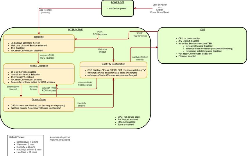
Business iQ (BiQ) Set-Back-Box Installation Guide

Document Control
© Copyright FOXTEL Management Pty Ltd. All rights reserved. This document
contains information proprietary to FOXTEL Management Pty Ltd. Except for the
purposes of evaluation, this document may not be reproduced, in whole or in part, in
any form, or distributed to any party outside of FOXTEL Management Pty Ltd, by any
means, without permission in writing, from FOXTEL Management Pty Ltd.
This document is classified to the level indicated at the top of this page. Any
classification containing the word confidence or confidential means the document is to
be placed out of sight when not in use and placed in a drawer or cupboard when the
room will be unattended. Any classification containing the word secret means the
document is always to be in someone’s hand or under secure lock when not in use.

History
  Version        Date              Author                         Description
     1.1     03/10/2020 Graham Briscoe             2ndrevision drafted from
                                                   BUS0403_BiQ_SBB_Installation_Guide_A4_F
                                                   A_Digital.pdf. Included casting setup and
                                                   hosted in-house channels.

Approval

                                                                   4 OCT 2020

 Graham Briscoe, Commercial Product Manager                             Date

Distribution List
 Name                              Position                               Company
 Christopher Smith                 Commercial Product Solutions Manager   Foxtel
 Doug Fewtrell                     Head of Field Operations               Foxtel
 Adam Brown                        Field Area Manager, VIC                BSA
 John Mitsios                      Commercial Manager, VIC                BSA
 Enver Vasfi                       Hardware Development Manager           Foxtel
 Steve Circosta                    Customer Technology Field Engineer     Foxtel

Printed: 4 OCT 2020
© FOXTEL Management Pty Ltd 2020              2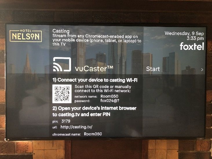
Business iQ (BiQ) Set-Back-Box Installation Guide

Disclaimer
This document is correct at time of publication. Foxtel reserves the right to modify items
within the document without prior notice to the field.
Refer to the Foxtel website for the latest version.

Printed: 4 OCT 2020
© FOXTEL Management Pty Ltd 2020           3

Business iQ (BiQ) Set-Back-Box Installation Guide

                                                  Table of Contents
Sections
1.      INTRODUCTION ............................................................................................................... 7
2.      THE SET-BACK-BOX ....................................................................................................... 7
     2.1.      OVERVIEW ................................................................................................................... 7
     2.2.      PHYSICAL ATTRIBUTES ................................................................................................. 7
     2.3.      ACCESSORIES.............................................................................................................. 8
     2.4.      SPECIFICATION ............................................................................................................ 9
     2.5.      SERIAL NUMBERING SCHEME ..................................................................................... 10
     2.6.      SAFETY INFORMATION ................................................................................................ 10
3.      PRE-INSTALLATION ...................................................................................................... 11
     3.1.      PROPERTY CREATION ................................................................................................ 11
     3.2.      SBB ASSIGNMENT ..................................................................................................... 11
     3.3.      FIRMWARE UPGRADES ............................................................................................... 11
     3.4.      ACCESSORIES............................................................................................................ 11
4.      ONSITE PREPARATION ................................................................................................ 12
5.      MOUNTING THE SET BACK BOX ................................................................................. 12
     5.1.      REQUIRED TOOLS ...................................................................................................... 13
5.1         SMALL FREE-STANDING TV (EST. 32” TO 45”) ..................................................... 13
6.      LARGE FREE-STANDING TV (EST. +45”) ................................................................... 15
     6.1.      WALL MOUNT TV ....................................................................................................... 16
7.      HARDWARE CONFIGURATION .................................................................................... 17
     7.1.      RF USE CASES .......................................................................................................... 17
     7.2.      CABLE CONNECTIONS ................................................................................................ 18
8.      SOFTWARE CONFIGURATION ..................................................................................... 19
     8.1.   BOOT SCREENS ......................................................................................................... 19
     8.2.   INSTALLATION SCREENS ............................................................................................. 20
       8.2.1.    Room Assignment Screen ............................................................................... 20
       8.2.2.    Premises Assignment Screen.......................................................................... 21
     8.3.   MAIN APPLICATION SCREENS ..................................................................................... 21
       8.3.1.    Welcome Screen ............................................................................................. 21
       8.3.2.    Casting ............................................................................................................. 22
     8.4.   STANDBY LOW POWER BEHAVIOUR ............................................................................ 23
9.      REMOTE CONTROL....................................................................................................... 24
     9.1.   PROGRAMMING THE REMOTE...................................................................................... 24
       9.1.1.   Setup Method 1 – Popular Brands .................................................................. 25
       9.1.2.   Setup Method 2 – Direct Code Entry ............................................................... 25
       9.1.3.   Setup Method 3: Code Search ........................................................................ 27
       9.1.4.   Setup Method 4: Learning from Other Remotes.............................................. 27
       9.1.5.   Resetting to Factory Default ............................................................................ 28
     9.2.   BATTERY REPLACEMENT ............................................................................................ 28
10.         IN ROOM SMOKE TEST............................................................................................. 28
11.         HIDDEN FEATURES................................................................................................... 29
     11.1.         SPECIAL KEY SEQUENCES ...................................................................................... 29
     11.2.         SETUP SCREENS.................................................................................................... 29

Printed: 4 OCT 2020
© FOXTEL Management Pty Ltd 2020                                    4
Business iQ (BiQ) Set-Back-Box Installation Guide

     11.2.1. Home Network ................................................................................................. 30
     11.2.2. Wifi Setup......................................................................................................... 30
     11.2.3. Video Resolution .............................................................................................. 32
   11.3.    MAINTENANCE SCREEN .......................................................................................... 32
     11.3.1. Casting Setup .................................................................................................. 33
     11.3.2. Move SBB to another Room ............................................................................ 37
   11.4.    DIAGNOSTIC SCREENS ........................................................................................... 37
12.       INTERNET CONNECTIVITY ....................................................................................... 38
   12.1.         OVERVIEW ............................................................................................................. 38
   12.2.         NETWORK CONFIGURATION .................................................................................... 38
   12.3.         NETWORK SECURITY .............................................................................................. 39
   12.4.         NETWORK BANDWIDTH ........................................................................................... 39
13.       IN-HOUSE CHANNELS .............................................................................................. 39
14.       PMS (PROPERTY MANAGEMENT SYSTEM)........................................................... 41
15.       DEFINITIONS, ACRONYMS AND ABBREVIATIONS ............................................... 41
16.       RELATED DOCUMENT .............................................................................................. 43
17.       CONTACTS ................................................................................................................. 43

Figures
Figure 1 Physical Outlook .......................................................................................................... 7
Figure 2 Front Panel View ......................................................................................................... 7
Figure 3 Back Panel View ......................................................................................................... 8
Figure 4 Installation Stage 1 - Small Free-Standing TV .......................................................... 13
Figure 5 Installation Stage 2 - Small Free-Standing TV .......................................................... 14
Figure 6 Installation Stage 1 - Large Free-Standing TV .......................................................... 15
Figure 7 Installation Stage 2 - Large Free-Standing TV .......................................................... 15
Figure 8 Installation Stage 1 - Wall Mounted TV ..................................................................... 16
Figure 9 Installation Stage 2 - Wall Mounted TV ..................................................................... 16
Figure 10 SBB Connections (RF Use Case 2) ........................................................................ 18
Figure 11 Position of IR Prism ................................................................................................. 19
Figure 12 Boot Screen ............................................................................................................. 19
Figure 13 Room Assignment Screen....................................................................................... 20
Figure 14 Premises Assignment Screen ................................................................................. 21
Figure 15 Example Welcome screen....................................................................................... 21
Figure 16 Casting Screen ........................................................................................................ 22
Figure 17 Casting Captive Portal............................................................................................. 22
Figure 18 Standby Low-Power Mode ...................................................................................... 23
Figure 19 BiQ Remote Control ................................................................................................ 24
Figure 20 Set-up Screen Main Menu....................................................................................... 30
Figure 21 Home Network Screen ............................................................................................ 30
Figure 22 Wifi Set-up Screen .................................................................................................. 31
Figure 23 Virtual Keyboard ...................................................................................................... 31
Figure 24 Maintenance Screen ............................................................................................... 33
Figure 25 Casting Config Screen ............................................................................................ 34
Figure 26 Casting Web Portal ................................................................................................. 35
Figure 27 Diagnostic Summary Page ...................................................................................... 37
Figure 28 Diagnostic Home Networking Page ........................................................................ 37
Figure 29 Diagnostic Tuner Information Page ......................................................................... 38

Printed: 4 OCT 2020
© FOXTEL Management Pty Ltd 2020                                  5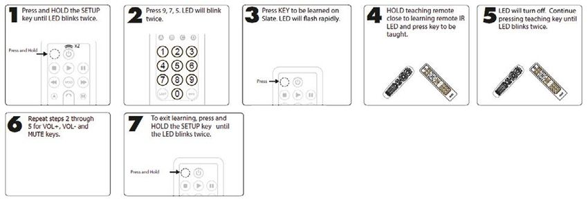
Business iQ (BiQ) Set-Back-Box Installation Guide

Tables
Table 1 Special Key Sequences .............................................................................................. 29
Table 2 In-house DTT Channel Centre Frequencies .............................................................. 41
Table 3 Definitions, Acronyms, and Abbreviations ................................................................. 42

Printed: 4 OCT 2020
© FOXTEL Management Pty Ltd 2020                              6

Business iQ (BiQ) Set-Back-Box Installation Guide

1.           Introduction
This document provides information and instructions to stage, install, and support
Business iQ (BiQ) enabled Set-Back-Boxes (SBBs) for Foxtel. The intended audiences
for this information include service provider management and install technicians.

2.           The Set-Back-Box

2.1.         Overview
The BiQ SBB is a 4k/HD hybrid satellite & terrestrial SBB with Wi-Fi capability designed
for the commercial market. The SBB is designed to operate on broadcast satellite,
terrestrial, and IP networks carrying TV signals encrypted by Irdeto Cloaked CA. VOD
services are carried over Ethernet using Google Widevine encrypt/decrypt. Irdeto
encryption and decryption is handled automatically as Irdeto keys are embedded into
the BiQ client software loaded on the box. Entitlement Management Messages (EMMs)
are sent over a dedicated satellite channel providing the decryption keys to view
programming on the SBBs.

2.2.         Physical Attributes
The physical outlook of SBB can be seen in Figure 1.

Figure 1 Physical Outlook

Figure 2 Front Panel View

Printed: 4 OCT 2020
© FOXTEL Management Pty Ltd 2020          7
Business iQ (BiQ) Set-Back-Box Installation Guide

Front panel features (see Figure 2):
(1) Embedded Chromecast device to support mobile device screen-casting.
(2) LED Indicator. The SBB is equipped with a dual color LED for the power state
    indication:
    • Green for operation mode, blinks green for Remote Control Unit (RCU) signal
       reception, LED will remain steady green if the set-back-box boots but is not
       assigned to a property. The LED turns off once assigned to a property.
    • Red for standby mode, displays for initial boot.
    Note: If the LED remains on after being assigned to a property, that indicates an
    issue with the SBB. Constant red typically indicates a hardware issue that may
    require replacement of the device.

Figure 3 Back Panel View
Rear panel features (see Figure 3):
(1) RF1-IN (DVB-S2) - connector for satellite signal reception.
(2) RF2-IN (DVB-S2, DVB-T2) - connector for satellite and/or terrestrial signal
    reception.
    Note: The SBB box has only 1 terrestrial tuner which is always tied to the external
    RF2-IN port. 4 satellite tuners are tied through an internal multiplexer to either the
    external RF1-IN port or the RF2-IN port.
(3) Ethernet port - recommend for BiQ deployments as this is the most reliable method
    by which BiQ 2-way application traffic flows.
    Note: If Ethernet is not available at a property, the SBB’s Wi-Fi interface must be
    configured for internet connectivity via the Setup Screens in Home Network 11.2.1.
(4) IR - connector for the external infra-red receiver input port. Since the SBB is
    typically mounted to the back of a TV — or otherwise kept out of sight an IR Eye
    Prism Extender Cable is used to pass RCU signals to the SBB.
(5) USB - USB port is used to upgrade the BiQ firmware via a USB stick. Refer to
    Firmware Upgrades in section 3.3 for more information.
(6) HDMI Out - HDMI output to the TV.
(7) POWER - check the power specifications before connecting the set-back-box to
    the wall outlet. See Safety Information in section 2.6.
(8) Embedded Google Chromecast device to support screen casting from mobile
    device.

2.3.         Accessories
The list of accessories that are included in the SBB product packaging are as follows:
(1) Power Supply Unit (PSU)
    • Wall-mount type
    • Outputting 12V DC to the SBB (1.5m cable)
    • Australian AS-3112 AC Plug
(2) Remote Control Unit (RCU), AA batteries included

Printed: 4 OCT 2020
© FOXTEL Management Pty Ltd 2020           8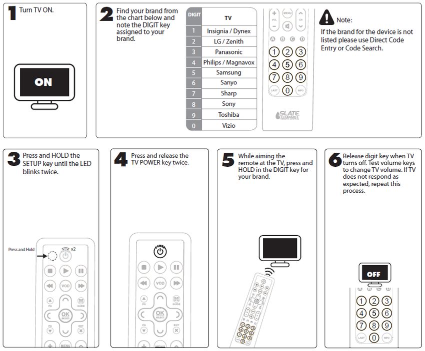
Business iQ (BiQ) Set-Back-Box Installation Guide

(3) Cables
    • 1 x IR Eye Prism type Extender Cable (1.0m)
    • 1 x HDMI 2.0 cable (1.0m)
    • 1 x Ethernet cable (1.0m)
(4) Mounting Brackets Kit, which allows SBB mounting to standard VESA points on
    back of TVs (32 inch and larger)
(5) Safety Guide

2.4.         Specification
 GENERAL
 Hardware platform                 ADB Ariel v2
                                   M-Star K7P, ARM based, dual core/1400DMIPS, 4K
 Chipset
                                   hardware
 RAM Memory                         2GB DDR4 system memory minimum
 Flash Memory                      16GB eMMC
 Mass Storage for DVR-Lite         eMMC
                                    Hybrid Satellite & Terrestrial front-end:
                                   • Quad DVB-S2 with DiSEqC 2.1 on RF1-IN /
 Front-End                             DiSEqC 1.1 on RF2-IN and Unicable SCR
                                   • Single DVB-T2
                                   • No RF loop-through
                                   (1) Ethernet (10/100 Mbps), (2) Wi-Fi client 802.11ac
 Network Connectivity
                                   dualband 2.4GHz/5GHz switchable
                                   (1) Irdeto Cardless Cloaked CA, (2) Widevine Level 1
 Security CA/DRM                   DRM, (3) HDCP 2.2 for HDMI 2.0b, (4) HW ready for
                                   watermarking (Irdeto compatible)
 Google Chromecast                 Casting functionality compliant with Chromecast-
 module                            enabled apps
 Software                          ADB vuTyme Client
 Environmental                     Operating Temperature Range from 5 to 45*C
 Anti-tamper                       Sticker (label/seal) + torx screws

 DECODER
 Classification                    4K HEVC / VP9 / HDR-10 / HLG
                                   • SD: PAL (576i)
 Video Output                      • HD: 576p60, 720p60, 1080i60, 1080p60
                                   • 4K/UHD: 2160p60
                                   • MP@L4.1, HP@L4.2, bitrate up to 20Mbps
                                   • H.265 (HEVC) Main-10 Level 5.1, bitrate up to
 Video Decoders
                                      30Mbps
                                   • VP9 bit rate up to 20Mbps
                                   • MPEG-1 layer 1, 2, 3 (MP3)
 Audio Decoders                    • Dolby Digital and Dolby Digital Plus
                                   • High-Efficiency AAC (Profile v1)

 INTERFACES
 Indicators                        2x Color LED (Power State)

Printed: 4 OCT 2020
© FOXTEL Management Pty Ltd 2020             9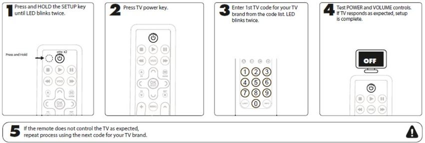
Business iQ (BiQ) Set-Back-Box Installation Guide

    Infra-Red                      IR 38kHz with support for Motorola RCU protocol
    Wi-Fi                          802.11ac Dual band 2.4/5GHz switchable
    Bluetooth                      4.2
                                   2 x F-Type Connectors (ANSI/SCTE 02 2006 for “F”
                                   Port):
                                   • One connector dedicated to DVB-S2 satellite
    RF Inputs
                                       contents only (RF1)
                                   • One connector for both mixed DVB-S2 satellite
                                       and DVB-T2 terrestrial contents (RF2)
                                   1x HDMI type A connector, version v2.0b with HDCP
    HDMI OUT
                                   2.2
    IR Jack                        1 x Mini-Jack 3.5” for IR Extender
    Ethernet                       1 x RJ-45 for Fast Ethernet (10/100 Mbps)
    Power                          12V DC Power Jack
    USB                            1 x USB 3.0

    ENCLOSURE
                                   210 x 235 (291) x 36 mm (W x H x D), (291) in case
    Dimensions
                                   of Chromecast
    Mounting kit                   Bracket kit to connect to TV set

2.5.            Serial Numbering Scheme
Example:
       BFTV A 9 09 12345
Where:
•     BFTV = account code
•     A = Advanced
•     9 = Last number in manufacturing year (2019 = 9, 2020 = 0)
•     09 = Two-digit week number
•     12345 = Five-digit unit number (from 00001-99999)

2.6.            Safety Information
Please review the following key safety instructions before handling and operating the
SBB. Also read the safety guide included within the SBB.
(1) The SBB is designed for use only with the supplied external power supply adapter.
    Do not use any other power supply.
(2) The order of connecting the power supply is as follows:
    • Connect the 12V cable to the SBB first.
    • Insert the power supply into the power outlet.
(3) To disconnect the SBB from the power, remove the external power supply adapter
    from the power outlet (not by removing the 12V cable from the SBB).
(4) Disconnect the power supply from the power outlet before you disconnect any
    equipment from the rear panel of the SBB.
(5) The product shall be used and installed indoor with a maximum ambient
    temperature of 45°C.

Printed: 4 OCT 2020
© FOXTEL Management Pty Ltd 2020            10
Business iQ (BiQ) Set-Back-Box Installation Guide
Note: Operating the SBB above 45°C shall void warranty and reduce the lifespan
of the product.
(6) Allow some free space above and around the SBB to ensure a free flow of air
around it.
(7) Don’t block the ventilation holes of the SBB.
3. Pre-Installation
3.1. Property Creation
The property where the SBBs will be installed must be built out in the BiQ back-office
system and made active by Foxtel before SBB install. Property setup includes creating
the property, enabling features, setting up channel line-ups, creating property areas
(e.g. Room, Public Viewing & Digital Signage), configuring broadcast settings (e.g.
multistacker or 5-wire), and more.
3.2. SBB Assignment
Foxtel will not allow any SBB on to the BiQ service unless the boxes are preloaded
into the BiQ server’s inventory. Boxes not preloaded into the BiQ inventory cannot be
installed. The process is as follows:
(1) When a new Foxtel customer schedules an install, the SBB order is sent to the
Foxtel warehouse vendor (Acer). The Foxtel warehouse picks the SBBs to be
installed to a property and sends the SBBs to the property (or install team). The
warehouse provides Foxtel with a list all SBB serial numbers sent to the property
(or install team).
(2) Using the back-office system Foxtel logically moves all those SBBs to the property
into room 0 (designated as the inventory room). This way, when technicians
physically install the SBBs, they only have to choose the area and set the room
number of each SBB to install them (see section 8.2.1).
3.3. Firmware Upgrades
SBBs shall typically be installed on-site with original factory firmware and then either
upgraded to the most current version remotely after the installation by Foxtel Business.
However, SBBs may be upgraded beforehand automatically by Foxtel if required.
SBBs are required to be connected via Ethernet or Wi-Fi and powered on. Automatic
download will then occur if the SBB has old firmware.
A USB stick can also be used to manually initiate an upgrade of software on-site or in
a pre-install environment. The firmware file is made available by Foxtel for the
technician to download. The technician copies the file to an empty USB stick (FAT32
format). The USB stick can then be inserts it into the SBB and the on-screen prompts
followed to complete the firmware upgrade.
3.4. Accessories
The required length of cables for the installation should be checked prior to installation.
If longer than the standard lengths supplied with the SBB (refer to section 2.3) then
alternative cables or extenders shall need to be sourced prior to install.
Printed: 4 OCT 2020
© FOXTEL Management Pty Ltd 2020 11Business iQ (BiQ) Set-Back-Box Installation Guide
4. Onsite Preparation
Perform an internet speed test on the property’s:
Ethernet network (if to be used) at the wall plate a SBB is to be connected to.
Wifi network (if to be used) allocated to Foxtel.
Note: The internet download bandwidth of the speed test is required to be greater
than 256Kbps for the SBB to boot. A minimal 512Kbps is required for every 10
SBB. If On Demand is required by the property, a minimum of 2.7Mbps is required
for the SBB to playback SD quality VOD and 6.3Mbps for Full HD VOD. See section
12.4 for more information regarding bandwidth requirements.
Check the DVB‐S/S2 satellite signal (if used) at the wall-plate is between 59dBuV
and 76dBuV.
Check the DVB‐T/T2 terrestrial signal (if used) at the wall-plate is between 54dBuV
to 77dBuV.
Configure one SBB as per Hardware Configuration in chapter 7 and Software
Configuration in chapter 8.
Contact Foxtel's Business support team on 1300 874 403 to send Foxtel channels
entitlement hit to the SBB.
Confirm branding of the Welcome screen UI (property logo, property background
image, colours, etc.) is appropriate for the property.
Confirm there are no TV video resolution issues (i.e. clear UI picture and video).
If FTA is available at the wall plate confirm the SBB automatically performs a linear
TV scan during first installation.
Note: To initiate a manual scan press the remote control key sequence Red C, Red
C, 8, 8, 8, .
Tune to every FTA terrestrial channel in channel line-up (ch# 1-99) to check which
do not have signal. Compile a list of any channels that do not have signal in order
that Foxtel's Business support team can resolve the issues.
Note: FTA availability is location and antenna dependent. Which FTA channels
have no signal can only be determined on-site.
Tune to every channel Ch 100 - 999 to test AV playback. Compile a list of any
channels that do not have signal in order that Foxtel's Business support team can
resolve the issues.
Note: No channels should display ‘No Signal’ after receiving their entitlement hit.
Initiate playback of an On Demand title to test VOD audio/video playback.
Cast YouTube (if casting required by the property).
5. Mounting the Set Back Box
This chapter explains the recommended methods of installing a SBB dependent of the
position and/or size of TV. In all cases the recommended position of the SBB is with
cables pointed downwards.
Note: Depending upon your local installation situation, you may want to mount the SBB
before or after performing Hardware Configuration in chapter 7 and Software
Configuration in chapter 8.
WARNING
In case the SBB is installed within a limited space or with other electrical equipment
aside from a TV (e.g. stacked with other SBBs) the following should be observed:
• The environment should be air-conditioned with ambient temperature 25⁰C or
lower.
Printed: 4 OCT 2020
© FOXTEL Management Pty Ltd 2020 12Business iQ (BiQ) Set-Back-Box Installation Guide
• The SBB should be mounted in vertical position, preferably with the side panel
having cable connections facing down.
• If the SBB cannot be mounted vertically, it should stand horizontally on a perforated
surface to improve air circulation.
• Additional electrical equipment (e.g. other SBBs) should be placed at a minimum
distance of 50 cm from the SBB.
• The ambient temperature halfway between the SBB and other electrical equipment
should be confirmed to be no more than 45°C. If over 45°C, extend the distance
between units.
5.1. Required Tools
The following tools are required to install a SBB:
P0 screwdriver (diameter 4.5mm) for spacer screws
P1 screwdriver (diameter 3mm) for small screws
Cordless drill with 5mm step cone drill bit (in case holes in TV brackets need to be
expanded to fit mounting screws)
Terrestrial (FTA) & Satellite Digital TV signal meter for measuring signal strength
Mobile device (smart phone, tablet or laptop) with:
Latest version of OS
Latest version of Google Home application (if casting required by property)
Latest version of Ookla internet speed test application
5.1 Small Free-Standing TV (est. 32” to 45”)
Stage 1 (Figure 4)
(1) Gather the set-back-box, the large mounting bracket, spacers, washers and
screws.
(2) Mount the mounting bracket to the set-back-box as shown.
(3) Secure the bracket to the set-back-box by using the smallest screws (4) in the
mounting kit.
Figure 4 Installation Stage 1 - Small Free-Standing TV
Printed: 4 OCT 2020
© FOXTEL Management Pty Ltd 2020 13Business iQ (BiQ) Set-Back-Box Installation Guide
Stage 2 (Figure 5)
(4) Gather 2 long screws, 2 spacers and 2 washers from the mounting kit. These will
be used to connect the SBB to the back of the TV.
(5) 3 long screw sizes are provided. If you are unsure which one to use, test screwing
each one in the mount holes to determine which size to use.
(6) Fasten the long screws on the back of the TV in the following order from top to
bottom: Long Screw >> Washer >> Spacer >> SBB & Bracket
Figure 5 Installation Stage 2 - Small Free-Standing TV
Printed: 4 OCT 2020
© FOXTEL Management Pty Ltd 2020 14Business iQ (BiQ) Set-Back-Box Installation Guide
6. Large Free-Standing TV (est. +45”)
Stage 1 (Figure 6)
(1) Gather the set-back-box, both mounting brackets, mounting cylinders, washers
and screws
(2) Mount the mounting brackets to the set-back-box.
(3) Secure the brackets to the set-back-box by using the smallest screws in the
mounting kit.
Figure 6 Installation Stage 1 - Large
Free-Standing TV
Stage 2 (Figure 7)
(4) Gather 2 long screws, 2 spacers and 2 washers from the mounting kit. These will
be used to connect the SBB to the back of the TV.
(5) 3 long screw sizes are provided. If you are unsure which one to use, test screw in
the mount holes to determine which size to fits.
(6) Fasten the long screws on the back of the TV in the following order from top to
bottom: Long Screw >> Washer >> Spacer >> SBB & Bracket
Figure 7 Installation Stage 2 -
Large Free-Standing TV
Printed: 4 OCT 2020
© FOXTEL Management Pty Ltd 2020 15Business iQ (BiQ) Set-Back-Box Installation Guide
6.1. Wall Mount TV
Stage 1
(1) Whether mounting to a small or larger TV, gather 2 more long screws, 2 spacers
and 4 washers from the mounting kit.
(2) You will have a total of 4 screws, 4 spacers, and 6 washers to install.
(3) Mount items to the TV in the following order (from top to bottom).
a. SBB Side (not shown in Figure 8): Long Screw >> Lock Washer >> Washer
>> Wall Mount Rail >> Spacer >> SBB Mounting Bracket(s)
b. Non SBB Side (shown in Figure 8): Long Screw >> Lock Washer >> Washer
>> Wall Mount Rail >> Spacer >>Washer
Note: If the wall-mounting kit excludes lock washers, exclude them from these
instructions.
Figure 8 Installation Stage 1 -
Wall Mounted TV
Stage 2 (Figure 9)
(4) Mount the TV to the main mount plate and then to the wall.
Figure 9 Installation Stage 2 -
Wall Mounted TV
Note: The SBB is installed between the TV and the TV’s mounting bracket.
Printed: 4 OCT 2020
© FOXTEL Management Pty Ltd 2020 16Business iQ (BiQ) Set-Back-Box Installation Guide
7. Hardware Configuration
Follow the procedures in the subsections bellow to connect the SBBs on-site.
7.1. RF Use Cases
It is important to understand the satellite and terrestrial setup at the property as well
as the wiring in the property prior to installation. Depending upon what this
configuration is will determine how the SBB shall be connected. Furthermore, this
configuration determines what settings need to be made for the property in the BiQ
back-office system. The key questions to answer are the following:
• Is there property using Ethernet IP for live TV video distribution to the wall plate
(via the vuStreamer IPTV Headend)? If so, skip this section unless there is FTA or
in-house terrestrial (COFDM) TV to the wall plate, as there are no RF connections
to be made.
• Is the property distributing FTA or in-house terrestrial (COFDM) TV to the wall
plate? If it is, that means that this signal is either on its own RF cable or may be
combined (diplexed) with a satellite lateral RF cable.
• Is the property distributing satellite using a Multi-stacker (combining satellite
laterals to one RF cable) to the wall plate? This means that only one RF cable
connects to the SBB for satellite live TV reception.
Note: FTA terrestrial TV may also be diplexed into this cable.
• Is the property wired for and using dual satellite laterals (Horizontal [18V] + Vertical
[13V])? This means that there are two satellite RF cables for each room that
connects to the SBB.
Find the use case below (1 to 6) that applies to your specific installation and use the
RF.
Note: The broadcast setting in the BiQ back-office should be configured by Foxtel
Business to reflect the use case before on-site installation.
Use Case 1: Multi-stacker Satellite Combined (Diplexed) with Terrestrial
Description: Single lateral (with horizontal + vertical stacked) for full Foxtel satellite
service with terrestrial stations diplexed on same feed
Connections: Connect the multi-stacked satellite RF cable that also combines the
terrestrial stations to RF2; RF1 is unused
Use Case 2: Multi-stacker Satellite + Terrestrial
Description: Single lateral (with horizontal + vertical stacked) for full Foxtel satellite
service. SBB terrestrial on a separate RF cable for local over-the-air services
Connections: Connect the multi-stacked satellite RF cable to RF1, and connect the
terrestrial RF cable to RF2
Use Case 3: Dual Satellite Laterals + Terrestrial
Description: Two laterals for full Foxtel satellite service (horizontal [18V] + vertical
[13V]). Terrestrial diplexed on 1 satellite lateral for local over-the-air services
Connections: Connect one RF cable to RF1, and connect the other cable that carries
the diplexed terrestrial signal with a satellite lateral to RF2
Printed: 4 OCT 2020
© FOXTEL Management Pty Ltd 2020 17Business iQ (BiQ) Set-Back-Box Installation Guide
Use Case 4: Dual Satellite Laterals No Terrestrial
Description: Two laterals for full Foxtel satellite service (horizontal [18V] + vertical
[13V]). No terrestrial.
Connections: Connect one RF cable to RF1, and connect the other cable to RF2
Use Case 5: Multi-stacker Satellite Only (No Terrestrial)
Description: Single Lateral (with horizontal + vertical stacked) for full Foxtel satellite
service
Connections: Connect the multi-stacked satellite RF cable to RF2; RF1 is unused
Use Case 6: Terrestrial (COFDM) Only
Description: No satellite. Terrestrial on a separate RF cable for local over-the-air
services.
Connections: Connect the terrestrial cable to RF2; RF1 is unused.
7.2. Cable Connections
Connect the SBB in the order listed below, as illustrated in Figure 10.
Figure 10 SBB Connections (RF Use Case 2)
(1) Connect RF cable(s) for the appropriate use case from the previous section.
(2) Connect the supplied Ethernet cable from the SBB’s Ethernet port to Ethernet port
in the room (if used).
(3) Connect the IR prism dongle into the IR port on the SBB. This provides line-of-sight
RCU control of the SBB (if the SBB will be mounted behind the TV). Affix the prism
end of the IR dongle to the TV. This may be done now or after install and mounting
of the SBB. Follow the instructions below and refer to Figure 11:
• Peel the backing off the adhesive tape on the IR prism dongle to affix to the TV,
ideally to the bottom center of the back of the screen. Make sure the area on
the TV is clean and dry. You may want to wait until the SBB is mounted before
affixing the IR prism to the TV.
• The IR prism should be mounted facing downward so the 45⁰ angle is facing
toward the back of the TV and the wire is coming out towards the top. Route
the wire so there isn’t any pressure pulling on the bonded prism dongle.
Printed: 4 OCT 2020
© FOXTEL Management Pty Ltd 2020 18Business iQ (BiQ) Set-Back-Box Installation Guide
• Between ⅛ and ¼ of the prism should protrude below the TV and have clear
line-of-sight access to the room.
Figure 11 Position of IR Prism
Note: If the IR extender cable is not firmly clicked into place at both ends (into the
prism and SBB’s IR port) the SBB shall not receive any IR commands.
(4) Connect the HDMI cable from the SBB to the TV’s default HDMI port (typically
HDMI 1). Ensure the TV is powered on and set to the TV’s default HDMI port.
(5) Connect the power in this order:
a. connect the power supply to the back of the SBB;
b. connect the power supply to the power outlet.
Note: Reverse the order when disconnecting the SBB from power.
(6) As the SBB boots, observer the LED behaviour:
• Green for operation mode, blinks green for RCU signal reception, LED will
remain steady green if the box boots but is not attached to a property. The LED
turns off once attached to a property.
• Red for standby mode, displays quickly for initial boot.
Note: If the LED remains on after being assigned to a property, it may indicate an
issue with the SBB. Constant red typically indicates a hardware issue that may
require a replacement of the device.
(7) Refer to chapter 8 software boot sequence and behaviour on the TV screen
thereafter.
8. Software Configuration
8.1. Boot Screens
When the SBB boots the splash screen in Figure 12 is displayed.
Figure 12 Boot Screen
Printed: 4 OCT 2020
© FOXTEL Management Pty Ltd 2020 19Business iQ (BiQ) Set-Back-Box Installation Guide
Boot progresses is shown as follows:
(1) 1 dot means the Booter software has been launched.
(2) 2 dots mean that Drivers plus Middleware software has been launched.
(3) 3 dots mean that the client application/UI (user interface) software has been
launched.
If a SBB boots successfully one of the screens in the sections below shall be displayed,
dependent on if the SBB has been previously configured for the property.
Note: For the client application to load successfully internet connectivity must be
established with the BiQ server for the SBB to obtain its configuration. Refer to section
11.2.1 to configure the SBB for either Ethernet (default) or Wi-Fi connection to the
internet. Refer to section 12.4 for internet bandwidth requirements for the SBB to
successfully boot and expected boot time.
8.2. Installation Screens
8.2.1. Room Assignment Screen
Spare SBBs at a property are assigned to room 0. They are moved from the spare
inventory to the desired room using the room assignment screen. After the SBB boots
the room assignment screen in Figure 13 should automatically be displayed.
Figure 13 Room Assignment Screen
(1) Select an Area for the SBB (e.g. Room, Public Viewing or Digital Signage). Press
the OK key to open the list of areas and use the arrow buttons to select the desired
area. Press OK again to confirm selection.
(1) Unless otherwise instructed enter the room number as it physically appears on the
door. Remove the default leading zero by pressing the left button on the remote if
the room number does not have a leading zero. For non-room locations (such as
public areas) use the following numbering conventions scheme: 70000 and up –
common spaces; 80000 and up – restaurant or bar-restaurant; 90000 and up –
standalone bar.
Note: Room numbers must be unique across areas. For example, there cannot be
a room 100 in a Room area and a room 100 in a Public Viewing area. The install
screen will alert you if you try to use the same room number in different areas.
(2) The riser number is optional and can be left as default, or a number entered as
appropriate.
(3) Enter the premises PIN. If not 1234 (default), contact the Foxtel Business support
team.
Printed: 4 OCT 2020
© FOXTEL Management Pty Ltd 2020 20Business iQ (BiQ) Set-Back-Box Installation Guide
Note: Foxtel requires all SBBs to be preloaded into the BiQ back-office system for
security. If a SBB is not preloaded you will get an error when you Submit. Refer to
section 3.2 for more information.
8.2.2. Premises Assignment Screen
If the premises assignment screen in Figure 14 is displayed, contact Foxtel Business
to move the SBB to the desired premises. Once the SBB has been moved to a premise,
the room assignment screen in Figure 13 should automatically be displayed. Assign
the SBB to a room as per section 8.2.1.
Figure 14 Premises Assignment Screen
8.3. Main Application Screens
8.3.1. Welcome Screen
Once a SBB is assigned to a room (as per 8.2.1) a SBB in the ‘Room’ or ‘Public
Viewing’ area should boot to the Welcome screen (see Figure 15).
Figure 15 Example Welcome screen
If casting is required for the property (typically the case for SBBs in the ‘Room’ area)
refer to section 11.2.3 for how to configure the SBB and embedded Google
Chromecast.
Printed: 4 OCT 2020
© FOXTEL Management Pty Ltd 2020 21Business iQ (BiQ) Set-Back-Box Installation Guide
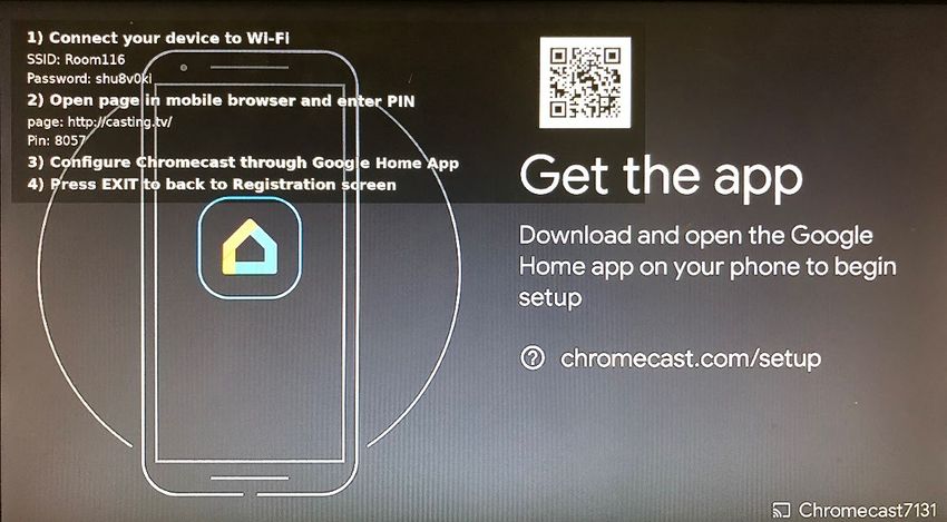
8.3.2. Casting
Foxtel’s casting solution prevents a guest in one room casting to a TV in another
room. A SBB generates a WiFi AP (Access Point) when a guest selects the “Casting”
Figure 16 Casting Screen
option from the Welcome screen’s main menu on the TV. Once selected a casting
screen displays instruction on how a guest connects their mobile device to the SBB
unique WiFi AP (see Figure 16).
Since more than one guest may checked into a room, multiple guest mobile devices
can connect to the WiFi AP, but no mobile devices shall have internet access. Once
a guest connects to the WiFi AP a captive portal (casting.tv) is displayed on the
guest’s mobile devices requesting a PIN code (see Figure 17). A guest can start
casting to Google Chromecast once they enter a one-time use PIN from the casting
screen on the TV into the captive portal on their mobile device. Any other mobile
Figure 17 Casting Captive
Portal
Printed: 4 OCT 2020
© FOXTEL Management Pty Ltd 2020 22Business iQ (BiQ) Set-Back-Box Installation Guide devices are automatically disconnected from the WiFi AP once a guest enters the correct PIN. During a casting session the guest shall have limited internet access on their mobile device via the WiFi AP. Internet access through the WiFi AP allows a guest to control the casting session on the integrated Chromecast (e.g. play/stop/pause streaming, change casted content or the casting app uses), whilst still being able to receive mails and remain on social media. The internet access is limited to 1Mbps. The bandwidth is throttled back intentionally to force the guest to use the property’s guest WiFi network for any significant internet usage, plus save as much of the internet bandwidth available to the SBB as possible for the Chromecast device whilst casting. A guest’s mobile device is disconnected from the WiFi AP one minute after casting is exited on the TV (e.g. when the guest switches to watching FTA or Foxtel TV channels, plays VOD or uses other features). A minute’s grace allows the guest to resume casting if they inadvertently exited casting. During SBB installation the channel for the Wifi AP (1 to 7 for 2.4GHz, and 36, 40 or 44 for 5GHz) is selected to avoid interference with other Wifi APs within the property (e.g. guest Wi-Fi). Refer to section 11.2.3 for how to configure the SBB and embedded Google Chromecast for casting. 8.4. Standby Low Power Behaviour Figure 18 illustrates how the SBB enters and exits standby low-power mode. Figure 18 Standby Low-Power Mode Note: • If no remote-control key is pressed within 5 minutes after power on the SBB will prompt the user to continue watching. Otherwise if a remote-control button is Printed: 4 OCT 2020 © FOXTEL Management Pty Ltd 2020 23
Business iQ (BiQ) Set-Back-Box Installation Guide

  pressed within 5 minutes, the SBB will prompt the user to continue watching TV
  after 4 hours of no other remote-control activity. If there is no remote-control activity
  after the prompt for a further 5 mins, the SBB shall enter standby state.
• Please contact Foxtel Business to request the standby state for SBBs installed
  assigned to the Public Viewing areas is disabled in the BiQ back-office.

9.           Remote Control

9.1.         Programming the Remote
For the BiQ remote control unit (see Figure 19) to control the Power, Mute and Volume
on the TV, it must be programmed to support the specific TV using one of the methods
described in the sections below. By default, the remote control is pre-programmed for
a Samsung TV.

Figure 19 BiQ Remote Control

Printed: 4 OCT 2020
© FOXTEL Management Pty Ltd 2020           24
Business iQ (BiQ) Set-Back-Box Installation Guide

9.1.1.       Setup Method 1 – Popular Brands

9.1.2.       Setup Method 2 – Direct Code Entry

Printed: 4 OCT 2020
© FOXTEL Management Pty Ltd 2020          25
Business iQ (BiQ) Set-Back-Box Installation Guide

Printed: 4 OCT 2020
© FOXTEL Management Pty Ltd 2020          26
Business iQ (BiQ) Set-Back-Box Installation Guide

9.1.3.       Setup Method 3: Code Search

9.1.4.       Setup Method 4: Learning from Other Remotes
For TV’s that are not supported by Popular Brands, Direct Code Entry or Code Search
methods of programming the BiQ’s Slate remote can learn from the TV’s remote
(teaching remote). There are two stages to programming the Slate remote from a
teaching remote. The first stage is to program the Slate remote’s SETUP (hidden key,
to left of Power key), VOL+, VOL- and MUTE keys from the learning remote’s POWER,
VOL+, VOL- and MUTE keys respectively:

The second stage is to program a macro for the Slate remote’s POWER key to control
the SBB.

Printed: 4 OCT 2020
© FOXTEL Management Pty Ltd 2020          27
Business iQ (BiQ) Set-Back-Box Installation Guide Note: The learning method can also be used if the remote is to power on/off the TV but control the volume via another device (e.g. sound bar). In which case in stage one the SETUP key would be learnt from the TV remote and volume keys from other device’s remote. 9.1.5. Resetting to Factory Default (1) Press and hold SETUP until the LED blinks twice (2) Press 9-7-7 The remote should now control a Samsung TV and the SBB. 9.2. Battery Replacement 10. In Room Smoke Test The following test shall be performed to check correct operation of the TV and SBB prior to notifying a customer the Foxtel service in a room is ready for use: Confirm the SBB remote control Vol+/- and Mute keys control the TV Exit to live TV and confirm the SBB remote control Power key momentarily displays the Welcome screen prior to the TV going into standby. Note: If the Welcome screen not displayed remote is incorrectly programmed and will not bring SBB out of standby. Confirm the SBB remote control Power key powers on the TV to the HDMI input the SBB is connected to (normally HDMI 1). Confirm the SBB automatically performs a linear TV scan during first installation. Note: To initiate a manual scan press the remote-control key sequence Red C, Red C, 8, 8, 8, from the Welcome screen. Initiate playback of an On Demand title (if On Demand is present in the main menu) to test VOD audio/video playback. Tune to an available terrestrial channel (any available for ch#1 – 99) to test AV playback. Tune to Ch 176 - TVSN (H-Pol) to test AV playback. Printed: 4 OCT 2020 © FOXTEL Management Pty Ltd 2020 28
Business iQ (BiQ) Set-Back-Box Installation Guide
Tune to Ch 652 - TRT World (V-Pol) to test AV playback.
Cast YouTube from a mobile device (optional if Casting is present in the main
menu)
Confirm there are no TV video resolution issues (i.e. clear UI picture and video).
Note: Contact Foxtel's Business support team on 1300 874 to send bulk Foxtel channel
entitlements to SBBs that are online after smoke testing (e.g. at end of day/installation).
11. Hidden Features
11.1. Special Key Sequences
Table 1 list the special key sequences to access hidden features, which are available
for troubleshooting and/or configuring the SBB. Some features are explained in more
detail within sections in the remainder of this chapter
Screen Remote Control Key Code Remark
Setup Screens Please contact Foxtel for confidential • Configure Wifi
key sequence • Factory Reset
• Manual satellite and/or
terrestrial (FTA) channel
scan
• Change video resolution
• Change CEC control
Maintenance Please contact Foxtel for confidential • Setup Chromecast
Screen key sequence • View firmware and
application/UI version
• View box telemetry
• Move SBB to another
room
• View the state of VOD
server connectivity
Channel Scan 8 8 8 • Manual terrestrial (FTA)
frequency scan
Diag Screens Press MENU to display the Welcome • Software versions
screen and then: • Serial number
3 4 2 4 • Ethernet & IP Information
• WiFi information (if
configured)
• Tuner signal information
Table 1 Special Key Sequences
11.2. Setup Screens
Refer to Table 1 for remote control key sequence to enter the main menu for the hidden
set-up screens in Figure 20. Use the Up/Down arrow remote control keys to select an
option and press OK to enter the option. Use the Left/Right arrow keys and OK to make
settings changes within an option. Press Exit to go back.
Printed: 4 OCT 2020
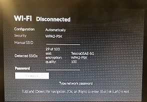
© FOXTEL Management Pty Ltd 2020 29Business iQ (BiQ) Set-Back-Box Installation Guide Figure 20 Set-up Screen Main Menu 11.2.1. Home Network Where Ethernet is not available for BiQ deployments the Wi-Fi interface on the SBB must be enabled in the Home Network screen by changing the Home Network option in Figure 21 from Ethernet (default) to Wifi (see also section 11.2.2 to configure Wi-Fi settings). The reverse can also be performed to switch from Wi-Fi back to Ethernet connectivity. Note: There should be to need to change options other than the Home Network on this screen unless instructed by Foxtel Business. Figure 21 Home Network Screen 11.2.2. Wifi Setup After switching internet connectivity to Wi-Fi as per section 11.2.1, the Wi-Fi interface is configured via the Wi-Fi setup screen (see Figure 22) using the instructions below, dependent on if the network (SSID) in visible (typically the case during first time institution at a property) or hidden. Printed: 4 OCT 2020 © FOXTEL Management Pty Ltd 2020 30
Business iQ (BiQ) Set-Back-Box Installation Guide

Figure 22 Wifi Set-up Screen
Visible Network
(1) Set Configuration to Automatic in Wi-Fi setup screen (if it is not already) by
    pressing OK on Configuration, using the left-arrow key to select Automatic and
    then pressing OK to confirm the selection.
(2) Navigate down to Detected SSIDs. Wait for Wi-Fi networks to be detected,
    then press OK key.
(3) Use the right/left arrow keys to choose the SSID allocated by the property to
    Foxtel and press OK to confirm.
    Note: The quality should be a minimum of 50 for correct operation of the SBB. If it
    is not, please inform Foxtel Business.
(4) Navigate down to Password and press OK to display the virtual keyboard in
    Figure 23.

    Figure 23 Virtual Keyboard
(5) Enter the password for the Wi-Fi network using the Left/Right arrow keys to
    select characters followed by the OK key to add the character to the
    password. When finished use the Left arrow key to select the ACCEPT
    button and press the OK key to confirm the password.
    Note: Press up arrow key changes to uppercase letters. Press down arrow key to
    revert to lower case.
(6) Press the down arrow key and select the Connect button. Then press the OK
    key. The SBB shall attempt to connect to the Wi-Fi network and if successful
    “Connected” shall be displayed at the top of screen. If unsuccessful,
    Disconnected shall be displayed.
    Note: If the SBB does not connect, please repeat the above steps and confirm
    the information entered is correct.
(7) Press the EXIT key twice to exit the hidden setup screens. The SBB will then
    proceed to boot as described in section 8.1.
Hidden Network
(1) Confirm what SSID (network name) and password is to be used by Foxtel at the
    property, plus the security used (None, WEP, WPA2-PSK, WPA-PSK).

Printed: 4 OCT 2020
© FOXTEL Management Pty Ltd 2020          31
Business iQ (BiQ) Set-Back-Box Installation Guide
(2) Set Configuration to Manual in Wi-Fi setup screen (if it is not already) by pressing
OK on Configuration, using the right-arrow key to select Manually and then
pressing OK to confirm the selection.
(3) Navigate down to Security and press OK. Use the right/left arrow key to select
the desired Wi‐Fi security option (None, WEP, WPA2‐PSK, WPA‐PSK) and press
the OK key to confirm.
(4) Navigate down to Manual (SSID) and press OK to display the virtual keyboard in
Figure 23.
(5) Enter the network name (SSID) for the Wi-Fi network using the Left/Right arrow
keys to select characters followed by the OK key to add the character to the
SSID. When finished use the Left arrow key to select the ACCEPT
button and press the OK key to confirm the password.
Note: Press up arrow key changes to uppercase letters. Press down arrow key to
revert to lower case.
(6) Navigate down to Password and press OK, which shall again display the virtual
keyboard in Figure 23 again.
(7) Enter the password for the Wi-Fi network using the Left/Right arrow keys to
select characters followed by the OK key to add the character to the
password. When finished use the Left arrow key to select the ACCEPT
button and press the OK key to confirm the password.
Note: Press up arrow key changes to uppercase letters. Press down arrow key to
revert to lower case.
(8) Press the down arrow key and select the Connect button. Then press the OK
key. The SBB shall attempt to connect to the Wi-Fi network and if successful
“Connected” shall be displayed at the top of screen. If unsuccessful,
Disconnected shall be displayed.
Note: If the SBB does not connect, please repeat the above steps and confirm
the information entered is correct.
(9) Press exit key twice to exit the hidden setup screens. The SBB will then proceed
to boot as described in section 8.1.
11.2.3. Video Resolution
EDID is the HDMI data exchange that occurs between the SBB and the TV which,
among other things, negotiates a resolution the SBB shall use that is supported by the
TV. However, if this fails (e.g. incompatibility with some TVs or non-original HDMI cable
is used) it may cause video display issues. The resolution can be manually configured
using the video resolution screen. 3840 × 2160 is required to display 4K/UHD channels
and 1920 x 1080 for Full HD channel. Please inform Foxtel Business in order that there
is a record on the change from the norm.
11.3. Maintenance Screen
Refer to Table 1 for remote control key sequence to enter the main menu for the hidden
maintenance screen in Figure 24. The maintenance screen is useful to make software
configuration changes while on‐site. These include:
• Setup of the Chromecast to use the Wi‐Fi access point within the SBB.
• View some box telemetry (e.g. MAC, IP address, software version, serial number)
• View the firmware and application/UI software version on the SBB
• Moving a SBB to/from a room/inventory
• View the state of VOD server connectivity
Printed: 4 OCT 2020
© FOXTEL Management Pty Ltd 2020 32Business iQ (BiQ) Set-Back-Box Installation Guide
Figure 24 Maintenance Screen
11.3.1. Casting Setup
Follow the steps below to set-up or reconfigure the SBBs integrated Wi‐Fi access point
and embedded Google Chromecast.
(1) Check the versions under Software in the maintenance screen (see Figure 22):
a. Is the firmware version is 5.2.3.2 or above? Under Software, a “FW vers:
unknown_parameter” usually means its above. Refer to section 3.3 if a
firmware upgrade is required.
Note: New factory fresh boxes delivered directly from the warehouse shall need
their firmware upgraded.
Note: Firmware version can also be checked from the Welcome screen’s main
menu (see section 8.3.1) by selecting Settings then About.
b. Is the application version 5.2.3.1 or above? If not, contact Foxtel Business to
change it to the latest in the BiQ back-office.
(2) Check the vuCaster button is present onscreen. If not, contact Foxtel Business to
enable casting for the property in the BiQ back-office.
(3) Navigate down to the vuCaster button and press OK on the remote control.
(4) If this is not a first-time installation and the room number has changed, select the
Default button and press OK to return the SBB configuration to default casting
values.
(5) Make sure Enabled is selected. If not, press OK on the Enable field and select
Enabled on the resulting pull‐down menu.
(6) The Chromecast Name and SSID defaults to area & room number configured in
the room assignment screen (see section 8.2.1) and shall normally not need to be
changed. However, if there are multiple SBBs assigned to a room, append A, B,
C, etc. to the Name and SSID (e.g. Room100A, Room100B).
Note: It is important the Name and SSID reflect the room number in order that a
guest will associate the Chromecast with the room number, which appears on the
Welcome screen.
Printed: 4 OCT 2020
© FOXTEL Management Pty Ltd 2020 33You can also read