User's Guide TIDA-00293 DLP 3D Printer User's Guide
←
→
Page content transcription
If your browser does not render page correctly, please read the page content below
TIDA-00293 DLP® 3D Printer User's Guide

User's Guide

                 Literature Number: DLPU025
                        September 2014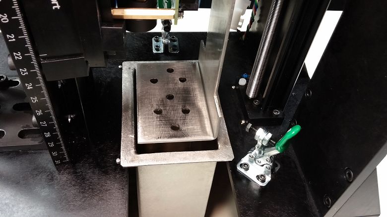
Contents

Preface ........................................................................................................................................ 6
1       Introduction to the DLP® 3D Printer Reference Design                         ............................................................. 7
        1.1      ................................................................................................................................. 7
        1.2    Stereolithography ............................................................................................................ 7
        1.3    How the DLP 3D Printer Reference Design Works ..................................................................... 7
               1.3.1 DLP Structured Light SDK ......................................................................................... 7
               1.3.2 Photo-resins ........................................................................................................ 7
               1.3.3 DLP LightCrafter™ 4500 Evaluation Module.................................................................... 7
               1.3.4 Velmex XSlide™ Translation Stage .............................................................................. 7
               1.3.5 Mechanical Structure ............................................................................................... 8
               1.3.6 DLP 3D Printer Microcontroller.................................................................................... 8
               1.3.7 Front Panel User Interface ........................................................................................ 8
               1.3.8 DLP 3D Printer Graphical User Interface ........................................................................ 8
               1.3.9 Object Layer Images ............................................................................................... 8
2       Installing the DLP® 3D Printer Reference Design...................................................................... 9
        2.1      ................................................................................................................................. 9
        2.2    Future Technology Devices International D2XX Driver Installation ................................................... 9
        2.3    Downloading the DLP 3D Printer Reference Design .................................................................. 13
        2.4    Installing the DLP 3D Printer Reference Design ....................................................................... 13
3       Using the DLP® 3D Printer Reference Design ......................................................................... 17
        3.1     ................................................................................................................................ 17
        3.2    Programming The MSTP Cape........................................................................................... 17
        3.3    Preparing The Hardware For Printing ................................................................................... 21
        3.4    Printing An Object .......................................................................................................... 27
4       Building the DLP® 3D Printer Reference Design from Source .................................................. 34
        4.1     ................................................................................................................................ 34
        4.2    Qt Creator Installation ..................................................................................................... 34
        4.3    OpenCV Build and Installation ............................................................................................ 41
        4.4    DLP 3D Printer Reference Design Project File Setup ................................................................. 52
5       DLP® 3D Printer Design Considerations ................................................................................ 56
        5.1     ................................................................................................................................ 56
        5.2    Hardware Design ........................................................................................................... 56
               5.2.1 Illumination Source ................................................................................................ 56
               5.2.2 Build Orientation ................................................................................................... 56
               5.2.3 Build Envelope And Voxel Resolution .......................................................................... 58
               5.2.4 Build Platform ...................................................................................................... 59
               5.2.5 Mechanical Structure ............................................................................................. 59
        5.3    Microcontroller Firmware Design ......................................................................................... 59
               5.3.1 State Machine ..................................................................................................... 59
               5.3.2 Communications With The PC .................................................................................. 60
               5.3.3 Motor Drive Functionality ......................................................................................... 60
               5.3.4 LCD Interface ...................................................................................................... 60
        5.4    DLP 3D Printer GUI Design ............................................................................................... 60
               5.4.1 DLP Structured Light SDK ....................................................................................... 60

2       Contents                                                                                                    DLPU025 – September 2014
                                                                                                                Submit Documentation Feedback
                                                  Copyright © 2014, Texas Instruments Incorporated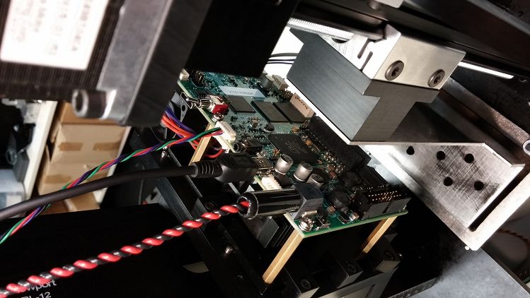
www.ti.com

               5.4.2   Multithreading ...................................................................................................... 60
               5.4.3   Qt Design Environment ........................................................................................... 61
6      Troubleshooting ................................................................................................................. 62
       6.1     General Troubleshooting Steps .......................................................................................... 62

DLPU025 – September 2014                                                                                                     Contents        3
Submit Documentation Feedback
                                               Copyright © 2014, Texas Instruments Incorporated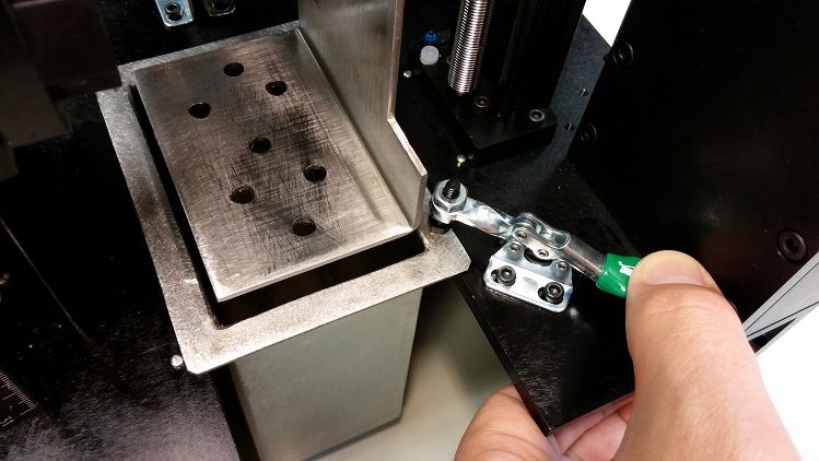
www.ti.com

                                                            List of Figures
    2-1.    FTDI D2XX Download ....................................................................................................... 9
    2-2.    Extracted FTDI Driver Files................................................................................................. 9
    2-3.    Devices and Printers In The Windows Start Bar ....................................................................... 10
    2-4.    TTL-232R-3V3 Properties Menu ......................................................................................... 10
    2-5.    Hardware Properties Button     ..............................................................................................   11
    2-6.    Change Settings Button For Hardware Properties .....................................................................            11
    2-7.    Update Driver Option ......................................................................................................     12
    2-8.    Browse Computer For Driver Files .......................................................................................        12
    2-9.    Select Driver File Folder ...................................................................................................   13
    2-10.   Begin The Update Of Drivers .............................................................................................       13
    2-11.   DLP 3D Printer Reference Design Installation Executable ...........................................................             14
    2-12.   DLP 3D Printer Reference Design Setup Wizard Screen .............................................................               14
    2-13.   DLP 3D Printer Reference Design License Agreement Screen......................................................                  15
    2-14.   DLP 3D Printer Reference Design Installation Path Selection .......................................................             15
    2-15.   DLP 3D Printer Reference Design Installation Confirmation .........................................................             16
    2-16.   DLP 3D Printer Reference Design File Installation Progress.........................................................             16
    2-17.   DLP 3D Printer Reference Design Installation Completion ...........................................................             16
    3-1.    Importing The DLP 3D Printer Firmware Project .......................................................................           18
    3-2.    CCS Project Import Source Selection ...................................................................................         19
    3-3.    CCS Project Importation Search .........................................................................................        19
    3-4.    DLP 3D Printer Firmware Project Path Selection ......................................................................           20
    3-5.    DLP 3D Printer Project Importation And Discovery ....................................................................           20
    3-6.    Uploading the DLP 3D Printer Firmware To The MSTP Cape .......................................................                  21
    3-7.    DLP 3D Printer Built Hardware ...........................................................................................       22
    3-8.    Resin Vat Placement ......................................................................................................      23
    3-9.    Resin Vat Locked In Position .............................................................................................      23
    3-10.   TTL-232R-3V3 Connected To DLP 3D Printer .........................................................................              24
    3-11.   LightCrafter 4500 USB Connection ......................................................................................         24
    3-12.   LightCrafter 4500 And TTL-232R-3V3 Cable Connected To PC ....................................................                   25
    3-13.   Connecting 12 V Power To The Printer .................................................................................          25
    3-14.   DLP 3D Printer Initialization Message ...................................................................................       26
    3-15.   DLP 3D Printer Initialized And Waiting ..................................................................................       26
    3-16.   Perforated Aluminum Build Plate In Place ..............................................................................         27
    3-17.   Executing The DLP 3D Printer Program ................................................................................           28
    3-18.   Setting The Image Folder .................................................................................................      29
    3-19.   Layer Image Folder Selection ............................................................................................       30
    3-20.   Printer Settings Check Before Sending Images To The Printer......................................................               31
    3-21.   Starting The Print Sequence ..............................................................................................      32
    3-22.   Object Layer Image Sequence Upload Completed ....................................................................               33
    3-23.   Beginning Of Object Printing..............................................................................................      33
    4-1.    Qt Creator IDE Installation ................................................................................................    34
    4-2.    Qt Creator IDE Installation Path Selection ..............................................................................       35
    4-3.    Qt Creator IDE Installation Component Selection .....................................................................           35
    4-4.    Qt Creator IDE End User License Agreement..........................................................................             36
    4-5.    Qt Creator IDE Ready To Install .........................................................................................       36
    4-6.    Qt Creator IDE Installing ..................................................................................................    37
    4-7.    Qt IDE Installation Completed ............................................................................................      37

4   List of Figures                                                                                            DLPU025 – September 2014
                                                                                                           Submit Documentation Feedback
                                             Copyright © 2014, Texas Instruments Incorporated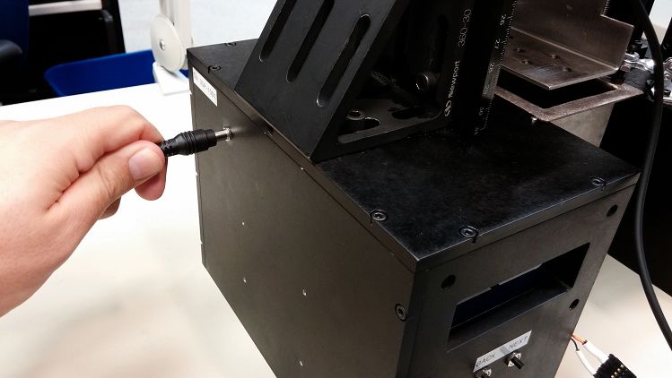
www.ti.com

       4-8.    Finding the MinGW Installation Path     ....................................................................................   38
       4-9.    System Environment Variables Editing ..................................................................................        39
       4-10.   System Properties Window ...............................................................................................       39
       4-11.   Editing the PATH Variable ................................................................................................     40
       4-12.   MinGW Directory Added to the PATH Variable ........................................................................            40
       4-13.   OpenCV Source Extraction Path .........................................................................................        41
       4-14.   OpenCV Source Extraction ...............................................................................................       41
       4-15.   Cmake Installation Entry ..................................................................................................    41
       4-16.   Cmake User License Agreement .........................................................................................         42
       4-17.   Cmake Installation Options ...............................................................................................     42
       4-18.   Cmake Installation Path ...................................................................................................    42
       4-19.   Cmake Installation Completed ............................................................................................      43
       4-20.   Cmake GUI Execution From Windows Start Button ...................................................................              43
       4-21.   Cmake GUI Source Selection ............................................................................................        44
       4-22.   OpenCV Source Selection In Cmake ....................................................................................          45
       4-23.   Cmake GUI Build Selection ...............................................................................................      46
       4-24.   Cmake GUI Configure Build ..............................................................................................       46
       4-25.   Cmake Compiler Configuration ...........................................................................................       47
       4-26.   Cmake Install Option Configuration ......................................................................................      48
       4-27.   Cmake Build Options Input ...............................................................................................      49
       4-28.   Cmake Make File Generation.............................................................................................        49
       4-29.   Opening a Command Line Window ......................................................................................           50
       4-30.   Starting the OpenCV Build Process .....................................................................................        51
       4-31.   Long OpenCV Build Process .............................................................................................        51
       4-32.   Installing the OpenCV Libraries ..........................................................................................     51
       4-33.   Opening the DLP 3D Printer Reference Design Project In Qt Creator ..............................................               52
       4-34.   QT .pro File Location ......................................................................................................   53
       4-35.   Configuring the QT .pro for Building .....................................................................................     53
       4-36.   Opening the QT .pro for Editing ..........................................................................................     54
       4-37.   Editing The Include Paths For OpenCV and FTDI Libraries..........................................................              54
       4-38.   Running The DLP 3D Printer Reference Design GUI .................................................................              55
       5-1.    Top-Down Build Method ...................................................................................................      57
       5-2.    Bottom-Up Build Method ..................................................................................................      58

DLPU025 – September 2014                                                                                                List of Figures        5
Submit Documentation Feedback
                                               Copyright © 2014, Texas Instruments Incorporated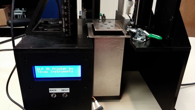
Preface
                                                                                          DLPU025 – September 2014

                                                                                        Read This First

About This Guide
     The DLP™ 3D Printer Reference Design enables faster development of 3D printing applications utilizing
     DLP platforms. This guide walks the user through the installation, operation, and recommended use
     settings of the DLP 3D Printer Reference Design, as well as building the GUI and microcontroller firmware
     from source code.

Related Documentation from Texas Instruments
     DLPC350 Datasheet: DLP Digital Controller for the DLP4500 DMD, DLPS029
     DLP4500 Datasheet: DLP® 0.45 WXGA DMD, DLPS028
     User's Guide: DLP® LightCrafter 4500™ Evaluation Module, DLPU011
     User's Guide: MSP430x2xx Family, SLAU144
     DRV8825 Datasheet: Stepper Motor Controller IC, DRV8825

If You Need Assistance
     Refer to the DLP and MEMS TI E2E Community support forums

Minimum System Requirements
     •   PC with 1GHz, or faster, 32-bit (x86) processor
     •   2 GB RAM
     •   10 GB of free hard-disk space
     •   Microsoft® Windows® 7 SP 1
     •   Microsoft Visual C++ 2010 Redistributable
     •   Microsoft Visual C++ 2012 Redistributable
     •   2x USB 2.0 port
     •   Qt Creator 5.3.0 Integrated Design Environment (IDE)
     •   OpenCV v2.4.9 Libraries
     •   DLP® LightCrafter 4500™ Evaluation Module
     •   Code Composer Studio™ v6
     •   Future Technology Devices International Ltd. D2XX Drivers 2.10.00
     •   Freesteel Z-level Slicer
     Note: The DLP 3D Printer Reference Design installation and setup is written for users that are familiar
     with navigating through Windows command line prompts and building executable binaries from source
     code.
     Note: The DLP 3D Printer Reference Design was created with the above listed versions of each software
     tool. Using newer versions of the software tools may render the code inoperable, and it shall be up to the
     user to make appropriate changes to the source code for compatibility.

6    Read This First                                                                         DLPU025 – September 2014
                                                                                         Submit Documentation Feedback
                                     Copyright © 2014, Texas Instruments Incorporated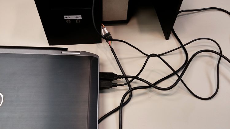
Chapter 1
                                                                                                      DLPU025 – September 2014

          Introduction to the DLP® 3D Printer Reference Design

1.1     The DLP 3D Printer Reference Design is a full hardware design enabling 3-dimensional printing of objects
        from cross-sectional images from meshed models. The reference design includes a lightweight GUI,
        electrical schematics, cable assembly drawings, and mechanical drawings to create the printer.

1.2     Stereolithography
        Stereolithography is an additive manufacturing method that employs a photo-curable resin. Exposing the
        photo-resin to successive 2-dimensional object cross sections create the 3-dimensional objects a single
        layer at a time. The resin, composed of monomers, cross-links when exposed to light of a sufficient energy
        level. The cross-linking of the monomers generates a polymer chain, creating a solid material where the
        resin was exposed. Stereolithography was traditionally achieved by outlining the object layer with a laser;
        DLP technology allows an entire layer to be exposed at once by dynamically masking a broad light source.

1.3     How the DLP 3D Printer Reference Design Works
        The DLP 3D Printer Reference Design consists of a LightCrafter 4500 evaluation module, a translation
        stage driven by a stepper motor, and a microcontroller at its core. The DLP 3D Printer Reference Design
        utilizes the DLP Structured Light SDK to perform the printed image creation and layer sequence for
        printed objects.

1.3.1    DLP Structured Light SDK
        A GUI on a host PC allows the user to upload the sliced object images to the DLP 3D Printer for storage
        and exposure. The sliced layers are combined into composite images and uploaded to the LightCrafter
        4500 along with their exposure sequence. The DLP Structured Light SDK prepares the layer images and
        contains development modules for preparing image sequences. The SDK source code is made available
        along with the GUI source code in the TIDA-00293 DLP 3D Printer design files package.

1.3.2 Photo-resins
        A host of photo-resins are available in the SLA market, offered by a handful of commercial manufacturers.
        Each resin has different physical properties lending themselves to specific applications. The DLP 3D
        Printer is built with a 420 nm light source, which allows the use of any resin that is curable at this
        wavelength or above. The resin used during the development of the DLP 3D Printer was sourced from
        www.buy3dink.com

1.3.3    DLP LightCrafter™ 4500 Evaluation Module
        The DLP 3D Printer Reference Design uses a modified LightCrafter 4500 projector to expose the photo-
        resin. The LightCrafter 4500 is modified with a 420 nm Philips Lumileds Luxeon® UV LED. The projection
        optics are also modified to allow the projector to focus at shorter distances, enabling higher resolution
        printed objects.

1.3.4 Velmex XSlide™ Translation Stage
        The printed objects form on a platform that translates on one axis only. The translation stage lowers the
        build platform a precise and accurate distance for each printed layer. This reference design uses the
        Velmex XSlide, which accepts NEMA 17 or 23 sized stepper motors and has integrated limit switches. The
        stage is highly rigid for it's small size to ensure repeatable positioning of the build platform.

DLPU025 – September 2014                                                 Introduction to the DLP® 3D Printer Reference Design   7
Submit Documentation Feedback
                                        Copyright © 2014, Texas Instruments Incorporated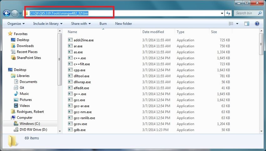
How the DLP 3D Printer Reference Design Works                                                                      www.ti.com

1.3.5 Mechanical Structure
        The DLP 3D Printer mechanical assembly is constructed from 0.25" thick aluminum plates to make the
        structure as rigid as possible. The structure's role is to hold the orientation of the build platform/translation
        stage, photo-resin vat, and projector tightly, in relation to each other, to reduce dimensional errors in the
        printed objects. The mechanical assembly features an easily removable photo-resin vat.

1.3.6     DLP 3D Printer Microcontroller
        The DLP 3D Printer has to synchronize motor control along with exposure of the object layers, as well as
        supply an interface with a front panel LCD screen and user buttons. An MSP430F2410 controls the
        operation of the DLP 3D Printer onboard a stand-alone capable BeagleBone Black MSTP Cape. The
        MSTP cape contains the microcontroller and a DRV8825 stepper motor control IC. The
        MSP430/DRV8825 combination is capable of driving bipolar and unipolar stepper motors with phase
        voltages between 8.2 V to 45 V. The DRV8825 can output up to 2.5 A of current at 24 V. The MSTP cape
        must be modified by the addition of connections between the microcontroller and header pins. The
        connections that must be added are highlighted in red in the cape schematic in the TIDA-00293 design file
        package.

1.3.7 Front Panel User Interface
        Users can interface with the DLP 3D Printer through a front panel once the print has been started. A 4-line
        LCD screen with 20 characters per line displays information to the user such as the number of print layers
        and the current layer in the print sequence. The LCD screen is controlled by the MSP430 through an
        HD44780 controller. The front panel also has two buttons allowing users to interact with the printer, either
        by responding to LCD prompts or pausing -- and even cancelling -- the print sequence.

1.3.8     DLP 3D Printer Graphical User Interface
        Object layer images are uploaded to the DLP 3D Printer hardware utilizing a GUI. Object layer images
        must be 912 × 1140 resolution due to the native resolution of the LightCrafter 4500. The images are
        processed by the DLP Structured Light SDK into a firmware file containing the sequence of layer images.
        The GUI takes a basic set of parameters from the user including: LED current setting, layer exposure time,
        z-layer step resolution, resin settling time, and the directory where object layer images are kept.

1.3.9 Object Layer Images
        Object layer images can be made by hand using a drawing utility, or created by slicing STL file models.
        STL files are the de facto standard input file for 3D printers, and are readily available in multiple online
        libraries. STL files can be sliced using the Freesteel slicer utility found here:
        http://www.freesteel.co.uk/wpblog/slicer/. The output image file format recommended is BMP. The output
        images should have a 16:10 aspect ratio as output from the slicer, but be resized to 912 × 1140. Resizing
        the images will change the aspect ratio, but the diamond array of the DLP4500 DMD will return the image
        to the proper 16:10 aspect ratio once projected. Object features should be colored white and the
        background should be black. Any white pixels in the object layer images will be printed in the resin.
        The object layer images must be isolated in a file directory and stored in alpha-numeric order. Freesteel
        slicer will handle this for the user if a static output file name is supplied. No other files should be kept in
        the directory with the layer images.

8       Introduction to the DLP® 3D Printer Reference Design                                         DLPU025 – September 2014
                                                                                                 Submit Documentation Feedback
                                              Copyright © 2014, Texas Instruments Incorporated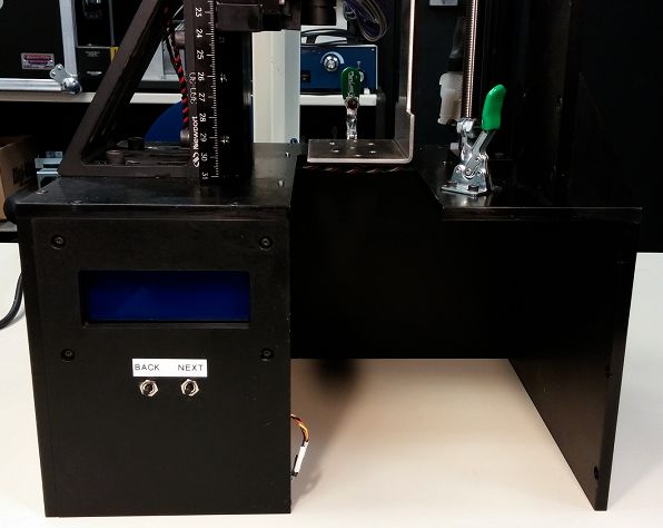
Chapter 2
                                                                                                      DLPU025 – September 2014

                      Installing the DLP® 3D Printer Reference Design

2.1    Before using the DLP 3D Printer Reference Design GUI, a few software dependencies and the reference
       design software itself, must be installed. The host PC communicates with the DLP 3D Printer controller
       through a USB to Serial adaptor by FTDI. The FTDI drivers must be installed before the GUI will run
       properly. Please read the following sections for more detailed instructions.

2.2    Future Technology Devices International D2XX Driver Installation
       The TTL-232R-3V3 device by FTDI allows a USB port on a Windows computer to communicate with TTL
       devices. The drivers are not automatically installed by Windows. Follow the procedure below to install the
       proper drivers.
       1. Go to the FTDI D2XX driver download site, located at http://www.ftdichip.com/Drivers/D2XX.htm and
          download the 32-bit Windows, as shown in Figure 2-1.

                                       Figure 2-1. FTDI D2XX Download
       2. Extract the downloaded .zip file into a convenient folder, as shown in Figure 2-2.

                                    Figure 2-2. Extracted FTDI Driver Files

DLPU025 – September 2014                                                      Installing the DLP® 3D Printer Reference Design   9
Submit Documentation Feedback
                                       Copyright © 2014, Texas Instruments Incorporated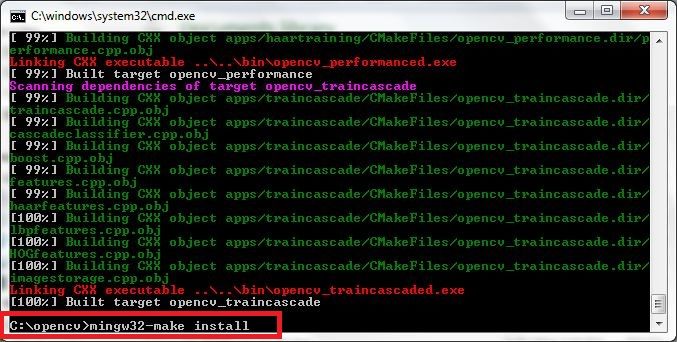
Future Technology Devices International D2XX Driver Installation                                                 www.ti.com

       3. After extraction of the driver files, click the Windows button and open Devices and Printers, as shown
          in Figure 2-3.

                             Figure 2-3. Devices and Printers In The Windows Start Bar

       4. Find the device labeled TTL232R-3V3 in the list of devices attached to the computer. Right click the
          device, and select Properties, as shown in Figure 2-4.

                                       Figure 2-4. TTL-232R-3V3 Properties Menu

       5. Enter the Hardware tab and click the Properties button, shown in Figure 2-5.

10     Installing the DLP® 3D Printer Reference Design                                              DLPU025 – September 2014
                                                                                                Submit Documentation Feedback
                                             Copyright © 2014, Texas Instruments Incorporated
www.ti.com Future Technology Devices International D2XX Driver Installation
Figure 2-5. Hardware Properties Button
6. Click the Change Settings button, highlighted in Figure 2-6. Click Yes on the prompt for administrator
privileges.
Figure 2-6. Change Settings Button For Hardware Properties
7. Enter the Driver tab, and click the Update Driver button, as shown in Figure 2-7.
DLPU025 – September 2014 Installing the DLP® 3D Printer Reference Design 11
Submit Documentation Feedback
Copyright © 2014, Texas Instruments IncorporatedFuture Technology Devices International D2XX Driver Installation www.ti.com
Figure 2-7. Update Driver Option
8. Click the Browse my computer option, shown in Figure 2-8.
Figure 2-8. Browse Computer For Driver Files
9. Click the Browse button that is highlighted in Figure 2-9. Select the folder containing the extracted
driver files from step 2, then click the OK button, as shown in Figure 2-9.
12 Installing the DLP® 3D Printer Reference Design DLPU025 – September 2014
Submit Documentation Feedback
Copyright © 2014, Texas Instruments Incorporatedwww.ti.com Downloading the DLP 3D Printer Reference Design
Figure 2-9. Select Driver File Folder
10. Click the Next button, shown in Figure 2-10.
Figure 2-10. Begin The Update Of Drivers
11. Windows will select the proper drivers from the extracted files and install them. The FTDI D2XX driver
installation is complete. Close all associated windows.
2.3 Downloading the DLP 3D Printer Reference Design
Compiled binaries for the DLP 3D Printer Reference Design are offered for convenience if the user does
not want to build them from source. The binaries are distributed along with the source code in a single
executable file which can be downloaded from the Texas Instruments Reference Design site. The source
code and pre-built program are distributed with the TI Design files in a .zip package.
2.4 Installing the DLP 3D Printer Reference Design
1. Decompress the "tidc***.zip" file in a convenient location.
2. Install the DLP 3D Printer Reference Design by executing the file "TIDA00293-***-windows-
installer.exe," as shown in Figure 2-11.
DLPU025 – September 2014 Installing the DLP® 3D Printer Reference Design 13
Submit Documentation Feedback
Copyright © 2014, Texas Instruments IncorporatedInstalling the DLP 3D Printer Reference Design www.ti.com
Figure 2-11. DLP 3D Printer Reference Design Installation Executable
3. Click the Next button on the install wizard setup screen, as shown in Figure 2-12.
Figure 2-12. DLP 3D Printer Reference Design Setup Wizard Screen
4. Read and review the license agreement for the DLP 3D Printer Reference Design, as shown in
Figure 2-13. Click the I accept the agreement radio button and then click the Next button to continue
installing the software.
14 Installing the DLP® 3D Printer Reference Design DLPU025 – September 2014
Submit Documentation Feedback
Copyright © 2014, Texas Instruments Incorporatedwww.ti.com Installing the DLP 3D Printer Reference Design
Figure 2-13. DLP 3D Printer Reference Design License Agreement Screen
5. Select an installation path where the reference design software will be located. Click the Next button,
as shown in Figure 2-14. Click the Next button to continue installing the software. Warning: Do not
include any spaces in the installation path for the reference design. Spaces will cause errors if the
software is built from source as described in Chapter 4!
Figure 2-14. DLP 3D Printer Reference Design Installation Path Selection
6. The installer is ready to install, click the Next button to start the process, as shown in Figure 2-15.
DLPU025 – September 2014 Installing the DLP® 3D Printer Reference Design 15
Submit Documentation Feedback
Copyright © 2014, Texas Instruments IncorporatedInstalling the DLP 3D Printer Reference Design www.ti.com
Figure 2-15. DLP 3D Printer Reference Design Installation Confirmation
7. Wait for the files to install in the location specified, as shown in Figure 2-16.
Figure 2-16. DLP 3D Printer Reference Design File Installation Progress
8. Once the files have been extracted and installed, click the Finish button to close the installer, as
shown in Figure 2-17.
Figure 2-17. DLP 3D Printer Reference Design Installation Completion
16 Installing the DLP® 3D Printer Reference Design DLPU025 – September 2014
Submit Documentation Feedback
Copyright © 2014, Texas Instruments IncorporatedChapter 3
DLPU025 – September 2014
Using the DLP® 3D Printer Reference Design
3.1 The DLP 3D Printer Reference Design application allows users to upload images that represent the cross-
sectional layers of a 3-dimensional object. The layers can be generated in a few methods including by
hand, automatically through a CAD utility, or a specific slicing tool designed for cutting a 3-dimensional
model into layers. Freesteel Slicer was used and can be found here:
http://www.freesteel.co.uk/wpblog/slicer/.
3.2 Programming The MSTP Cape
This section demonstrates how the DLP 3D Printer firmware is uploaded to the MSP430 on the MSTP
Cape. This method requires an MSP-FET430UIF JTAG debugging tool and Code Composer Studio v4 or
later.
1. Connect the MSP-FET430UIF ribbon cable to J5 of the BeagleBone MSTP cape.
2. Connect the MSP-FET430UIF USB connector to the PC loaded with Code Composer Studio v4 or
later.
3. Run Code Composer Studio.
4. Click the File tab in the menu bar, then click Import... as shown in Figure 3-1.
DLPU025 – September 2014 Using the DLP® 3D Printer Reference Design 17
Submit Documentation Feedback
Copyright © 2014, Texas Instruments IncorporatedProgramming The MSTP Cape www.ti.com
Figure 3-1. Importing The DLP 3D Printer Firmware Project
5. Expand the Code Composer Studio folder then click the CCS Projects item, as shown in Figure 3-2.
18 Using the DLP® 3D Printer Reference Design DLPU025 – September 2014
Submit Documentation Feedback
Copyright © 2014, Texas Instruments Incorporatedwww.ti.com Programming The MSTP Cape
Figure 3-2. CCS Project Import Source Selection
6. Click the Browse... button next to the search directory box, as shown in Figure 3-3.
Figure 3-3. CCS Project Importation Search
DLPU025 – September 2014 Using the DLP® 3D Printer Reference Design 19
Submit Documentation Feedback
Copyright © 2014, Texas Instruments IncorporatedProgramming The MSTP Cape www.ti.com
7. Select the folder "DLP_3D_Printer_Firmware" located in the TIDA-00293 Software installation path, as
shown in Figure 3-4, then click the OK button.
Figure 3-4. DLP 3D Printer Firmware Project Path Selection
8. After the project appears in the Discovered projects section, click the Finish button, as shown in
Figure 3-5.
Figure 3-5. DLP 3D Printer Project Importation And Discovery
9. The project DLP 3D Printer will display as Active in the Project Explorer window, as shown in
Figure 3-6. Click the start debug button in the toolbar, also shown in Figure 3-6.
20 Using the DLP® 3D Printer Reference Design DLPU025 – September 2014
Submit Documentation Feedback
Copyright © 2014, Texas Instruments Incorporatedwww.ti.com Preparing The Hardware For Printing
Figure 3-6. Uploading the DLP 3D Printer Firmware To The MSTP Cape
10. Code Composer Studio will build and upload the DLP 3D Printer microcontroller firmware to the
MSP430.
NOTE: During the project build and upload process, the user will likely be prompted to upgrade the
firmware on the MSP-FET430UIF. Do not accept the upgrade. Click the Ignore button to
upload the firmware.
11. After the firmware has been uploaded to the MSTP cape, disconnect the the MSP-FET430UIF from
the MSTP cape and reset the cape.
3.3 Preparing The Hardware For Printing
This section describes how to setup the DLP 3D Printer, and connect it to a PC for printing objects. The
instructions from Chapter 2 must be completed prior to these steps.
1. After constructing the hardware for the DLP 3D Printer using the TIDA-00293 design files, the printer
should look similar to Section 2.4.
DLPU025 – September 2014 Using the DLP® 3D Printer Reference Design 21
Submit Documentation Feedback
Copyright © 2014, Texas Instruments IncorporatedPreparing The Hardware For Printing www.ti.com
Figure 3-7. DLP 3D Printer Built Hardware
2. Place the resin vat in the printer base and place it securely against the alginment tabs, as shown in
Figure 3-8.
22 Using the DLP® 3D Printer Reference Design DLPU025 – September 2014
Submit Documentation Feedback
Copyright © 2014, Texas Instruments Incorporatedwww.ti.com Preparing The Hardware For Printing
Figure 3-8. Resin Vat Placement
3. Secure the vat in place by securing the latches on the base, as shown in Figure 3-9.
Figure 3-9. Resin Vat Locked In Position
4. Connect the TTL-232R-3V3 cable to the RS232 to MSTP Cape Cable Assembly (TI Drawing #
2514179), as shown in Figure 3-10. The black wire from the TTL cable aligns with the single wire pin
DLPU025 – September 2014 Using the DLP® 3D Printer Reference Design 23
Submit Documentation Feedback
Copyright © 2014, Texas Instruments IncorporatedPreparing The Hardware For Printing www.ti.com
on the cable to the printer.
Figure 3-10. TTL-232R-3V3 Connected To DLP 3D Printer
5. Connect the USB mini connector to the LightCrafter 4500, as shown in Figure 3-11.
Figure 3-11. LightCrafter 4500 USB Connection
24 Using the DLP® 3D Printer Reference Design DLPU025 – September 2014
Submit Documentation Feedback
Copyright © 2014, Texas Instruments Incorporatedwww.ti.com Preparing The Hardware For Printing
6. Connect both the USB cable from the LightCrafter 4500, and the TTL-232R-3V3 cable to a Windows 7
based PC, as shown in Figure 3-12.
Figure 3-12. LightCrafter 4500 And TTL-232R-3V3 Cable Connected To PC
7. Plug the 12 V power supply into the jack on the side of the DLP 3D Printer, as shown in Figure 3-13.
Figure 3-13. Connecting 12 V Power To The Printer
8. The DLP 3D Printer will power up, and the build platform will start to index. The platform will move all
DLPU025 – September 2014 Using the DLP® 3D Printer Reference Design 25
Submit Documentation Feedback
Copyright © 2014, Texas Instruments IncorporatedPreparing The Hardware For Printing www.ti.com
the way down to its limit, then up out of the resin vat. The display will initialize and display the
message shown in Figure 3-14.
Figure 3-14. DLP 3D Printer Initialization Message
9. Once the build platform has completed its travel -- and is located above the vat -- the LCD will display
the printer's name, as shown in Figure 3-15.
Figure 3-15. DLP 3D Printer Initialized And Waiting
26 Using the DLP® 3D Printer Reference Design DLPU025 – September 2014
Submit Documentation Feedback
Copyright © 2014, Texas Instruments Incorporatedwww.ti.com Printing An Object
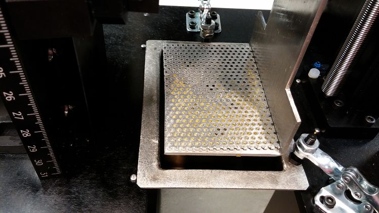
10. Place a piece of perforated aluminum on the build platform, as shown in Figure 3-16. This step can be
skipped IF the build platform is created out of aluminum. The photo-resin from www.buy3DInk.com,
tested during this design, had very poor adhesion to stainless steel.
Figure 3-16. Perforated Aluminum Build Plate In Place
11. The DLP 3D Printer is now ready to accept layer sequences from the PC.
3.4 Printing An Object
This section guides the user through using the DLP 3D Printer GUI to upload layer images to the printer
and start a print sequence. Ensure the steps from Section 3.3 have been completed.
1. Start the DLP 3D Printer Reference Design program, installed in Section 2.4, by running the
executable file, as shown in Figure 3-17.
DLPU025 – September 2014 Using the DLP® 3D Printer Reference Design 27
Submit Documentation Feedback
Copyright © 2014, Texas Instruments IncorporatedPrinting An Object www.ti.com
Figure 3-17. Executing The DLP 3D Printer Program
2. The DLP 3D Printer GUI will appear loaded with the default settings. Click the Set button to the right of
the Object Images Folder text box, as shown in Figure 3-18.
28 Using the DLP® 3D Printer Reference Design DLPU025 – September 2014
Submit Documentation Feedback
Copyright © 2014, Texas Instruments Incorporatedwww.ti.com Printing An Object
Figure 3-18. Setting The Image Folder
3. In the dialog box, select the folder where the cross-sectional images are located, as shown in Figure 3-
19. Highlight the folder and click the Select Folder button.
NOTE: The layer images must be 912 × 1140 resolution. Best results have been achieved with
BMP images. JPG images may be used, but layer quality will suffer due to lossy
compression methods employed in JPG.
DLPU025 – September 2014 Using the DLP® 3D Printer Reference Design 29
Submit Documentation Feedback
Copyright © 2014, Texas Instruments IncorporatedPrinting An Object www.ti.com
Figure 3-19. Layer Image Folder Selection
4. After the layer image folder has been selected, double check the settings for the print. The GUI should
look like Figure 3-20.
NOTE: The default settings are derived experimentally with resin produced by 3D Ink™,
purchasable here: http://www.buy3dink.com/p/59/uv-resin
Step resolution should be kept between 30 and 60 microns for best results but can be set
between 5 and 100 microns.
LED current should never be set above 35, and should only be set at 35 when the 420 nm
LED is placed on a metal core PCB.
Exposure time will be driven by a combination of layer thickness and LED current.
Resin settling time is the amount of time required for the resin's surface to return to level
after the build platform has moved.
30 Using the DLP® 3D Printer Reference Design DLPU025 – September 2014
Submit Documentation Feedback
Copyright © 2014, Texas Instruments Incorporatedwww.ti.com Printing An Object
Figure 3-20. Printer Settings Check Before Sending Images To The Printer
5. After verifying the print settings, click the Start Printing button, as shown in Figure 3-21.
DLPU025 – September 2014 Using the DLP® 3D Printer Reference Design 31
Submit Documentation Feedback
Copyright © 2014, Texas Instruments IncorporatedPrinting An Object www.ti.com
Figure 3-21. Starting The Print Sequence
6. The print sequence will take up to 10 minutes to prepare, and upload to, the projector. Do not
disconnect the PC from the DLP 3D Printer or close the GUI during this process. Either could corrupt
the firmware on the LightCrafter 4500. Wait for the message "You may now disconnect the PC from
the DLP 3D Printer" to be displayed, as shown in Figure 3-22.
32 Using the DLP® 3D Printer Reference Design DLPU025 – September 2014
Submit Documentation Feedback
Copyright © 2014, Texas Instruments Incorporatedwww.ti.com Printing An Object
Figure 3-22. Object Layer Image Sequence Upload Completed
7. The DLP 3D Printer will begin to move the build platform down and into the vat, and display the
message shown in Figure 3-23.
Figure 3-23. Beginning Of Object Printing
DLPU025 – September 2014 Using the DLP® 3D Printer Reference Design 33
Submit Documentation Feedback
Copyright © 2014, Texas Instruments IncorporatedChapter 4
DLPU025 – September 2014
Building the DLP® 3D Printer Reference Design from
Source
4.1 The DLP 3D Printer Reference Design application's source code is made available in the design files
installed in Chapter 2. The availability of the source allows users to modify, and build, the scanning
application on their own. Complete the installation of the necessary files before attempting to build the
application from source.
4.2 Qt Creator Installation
This section guides the user through the installation of the Qt Creator integrated development environment
(IDE.)
1. Download the Qt Creator IDE from the project webpage located here. Download the 32-bit Windows
version of Qt 5.2.1, or higher, that is bundled with MinGW. Note: This SDK uses C++11 and will not
compile using an out-of-date compiler. Use Qt 5.2.1, or later!
2. Execute the downloaded install file.
3. Click the Next button as shown in Figure 4-1.
Figure 4-1. Qt Creator IDE Installation
34 Building the DLP® 3D Printer Reference Design from Source DLPU025 – September 2014
Submit Documentation Feedback
Copyright © 2014, Texas Instruments Incorporatedwww.ti.com Qt Creator Installation
4. Select an installation path for the Qt IDE. Click the Next button as seen in Figure 4-2.
Figure 4-2. Qt Creator IDE Installation Path Selection
5. Choose the install components as shown in Figure 4-3. Make sure that MinGW is selected and click
the Next button.
Figure 4-3. Qt Creator IDE Installation Component Selection
DLPU025 – September 2014 Building the DLP® 3D Printer Reference Design from Source 35
Submit Documentation Feedback
Copyright © 2014, Texas Instruments IncorporatedQt Creator Installation www.ti.com
6. Review the license agreement and indicate you agree with the terms, shown in Figure 4-4. Then click
the Next button.
Figure 4-4. Qt Creator IDE End User License Agreement
7. Click the Next button as shown in Figure 4-5.
Figure 4-5. Qt Creator IDE Ready To Install
36 Building the DLP® 3D Printer Reference Design from Source DLPU025 – September 2014
Submit Documentation Feedback
Copyright © 2014, Texas Instruments Incorporatedwww.ti.com Qt Creator Installation
8. Wait for the installation to complete. Figure 4-6 shows the installation status bar.
Figure 4-6. Qt Creator IDE Installing
9. Once the Qt IDE installation has completed, click the Finish button as shown in Figure 4-7.
Figure 4-7. Qt IDE Installation Completed
DLPU025 – September 2014 Building the DLP® 3D Printer Reference Design from Source 37
Submit Documentation Feedback
Copyright © 2014, Texas Instruments IncorporatedQt Creator Installation www.ti.com
10. Using Windows Explorer, navigate to the Qt installation location and find the MinGW binary location.
Copy the path as shown in Figure 4-8.
Figure 4-8. Finding the MinGW Installation Path
38 Building the DLP® 3D Printer Reference Design from Source DLPU025 – September 2014
Submit Documentation Feedback
Copyright © 2014, Texas Instruments Incorporatedwww.ti.com Qt Creator Installation
11. Click the Windows button and type "edit the system environment" into the search box, shown in
Figure 4-9. Click the option labeled "Edit the system environment variables".
Figure 4-9. System Environment Variables Editing
12. Click the Environment Variables... button in the lower right corner, shown in Figure 4-10.
Figure 4-10. System Properties Window
DLPU025 – September 2014 Building the DLP® 3D Printer Reference Design from Source 39
Submit Documentation Feedback
Copyright © 2014, Texas Instruments IncorporatedQt Creator Installation www.ti.com
13. In the System variables section, browse to the entry labeled PATH. Highlight the entry and click the
Edit button, shown in Figure 4-11.
Figure 4-11. Editing the PATH Variable
14. Insert the path to the MinGW compiler binary directory in the PATH variable as shown in Figure 4-12,
then click the OK button. Note: Make sure that the entries are separated by a semicolon.
Figure 4-12. MinGW Directory Added to the PATH Variable
15. Click the OK button for the System properties window, then restart your computer. The installation of
the Qt IDE and MinGW is now complete.
40 Building the DLP® 3D Printer Reference Design from Source DLPU025 – September 2014
Submit Documentation Feedback
Copyright © 2014, Texas Instruments Incorporatedwww.ti.com OpenCV Build and Installation
4.3 OpenCV Build and Installation
This section details the steps taken to build the OpenCV libraries required for MinGW from the OpenCV
source files. Careful attention must be paid in this section for a successful build.
1. Download the OpenCV Version 2.4.6, or higher, Windows installation from http://opencv.org/.
2. Download the Cmake Version 2.8.12.2, or higher, Windows (Win32 Installer) from
http://www.cmake.org/cmake/resources/software.html.
3. Run the downloaded OpenCV file and click on the Extract button, shown in Figure 4-13.
Figure 4-13. OpenCV Source Extraction Path
4. Wait for the OpenCV libraries and source files to install. The installation path is shown in Figure 4-14.
Figure 4-14. OpenCV Source Extraction
5. Run the Cmake installation program downloaded in step 2. Click the Next button as shown in Figure 4-
15.
Figure 4-15. Cmake Installation Entry
DLPU025 – September 2014 Building the DLP® 3D Printer Reference Design from Source 41
Submit Documentation Feedback
Copyright © 2014, Texas Instruments IncorporatedOpenCV Build and Installation www.ti.com
6. Review the end-user license agreement for Cmake and accept the terms to continue with the
installation. The license agreement is higlighted in Figure 4-16.
Figure 4-16. Cmake User License Agreement
7. Accept the default settings for the Cmake installation. Select Do not add Cmake to the system PATH
variable as shown in Figure 4-17.
Figure 4-17. Cmake Installation Options
8. Choose an installation path for Cmake. Click the Next button, highlighted in Figure 4-18.
Figure 4-18. Cmake Installation Path
42 Building the DLP® 3D Printer Reference Design from Source DLPU025 – September 2014
Submit Documentation Feedback
Copyright © 2014, Texas Instruments Incorporatedwww.ti.com OpenCV Build and Installation
9. Once the Cmake installation is complete, click the Finish button highlighted in Figure 4-19.
Figure 4-19. Cmake Installation Completed
10. Search for, and run, the Cmake GUI that was installed in the previous step, an example of finding it is
shown in Figure 4-20.
Figure 4-20. Cmake GUI Execution From Windows Start Button
DLPU025 – September 2014 Building the DLP® 3D Printer Reference Design from Source 43
Submit Documentation Feedback
Copyright © 2014, Texas Instruments IncorporatedOpenCV Build and Installation www.ti.com
11. Inside of the Cmake GUI, check the box labeled "Grouped." Then click the Browse Source... button
highlighted in Figure 4-21.
Figure 4-21. Cmake GUI Source Selection
44 Building the DLP® 3D Printer Reference Design from Source DLPU025 – September 2014
Submit Documentation Feedback
Copyright © 2014, Texas Instruments Incorporatedwww.ti.com OpenCV Build and Installation
12. Browse to the /opencv/sources folder installed in step 3. Click the /sources folder as highlighted in
Figure 4-22, then click the OK button.
Figure 4-22. OpenCV Source Selection In Cmake
DLPU025 – September 2014 Building the DLP® 3D Printer Reference Design from Source 45
Submit Documentation Feedback
Copyright © 2014, Texas Instruments IncorporatedOpenCV Build and Installation www.ti.com
13. Click the Browse Build... button and select a path for the built libraries to be installed, shown in
Figure 4-23.
Figure 4-23. Cmake GUI Build Selection
14. Click the Configure button in the Cmake GUI, highlighted in Figure 4-24.
Figure 4-24. Cmake GUI Configure Build
46 Building the DLP® 3D Printer Reference Design from Source DLPU025 – September 2014
Submit Documentation Feedback
Copyright © 2014, Texas Instruments Incorporatedwww.ti.com OpenCV Build and Installation
15. A window will appear prompting the user to select the compilers to make the OpenCV libraries for.
Select MinGW makefiles from the drop down list, and select use default native compilers radio button.
The correct selections are highlighted in Figure 4-25. Click the Finish button.
Figure 4-25. Cmake Compiler Configuration
DLPU025 – September 2014 Building the DLP® 3D Printer Reference Design from Source 47
Submit Documentation Feedback
Copyright © 2014, Texas Instruments IncorporatedOpenCV Build and Installation www.ti.com
16. Cmake uses the instruction files located in the OpenCV source directory to configure build options.
This step may take a while and should complete with no errors in the lower status window as shown in
Figure 4-26. Note: If an error occurs immediately, check the PATH variable and ensure that the
directory to the MinGW compilers is correct, and the computer was restarted to make the changes
take effect.
Figure 4-26. Cmake Install Option Configuration
48 Building the DLP® 3D Printer Reference Design from Source DLPU025 – September 2014
Submit Documentation Feedback
Copyright © 2014, Texas Instruments Incorporatedwww.ti.com OpenCV Build and Installation
17. Cmake will provide the user with a host of options for the OpenCV build. The options will appear in
red before they are accepted by Cmake. Expand the group called CMAKE and find the variable
named CMAKE_BUILD_TYPE, as shown in Figure 4-27. Populate the empty Value box next to
CMAKE_BUILD_TYPE with "Release" then click the Configure button. All the options should turn
white, and no errors should be reported in the lower status window.
Figure 4-27. Cmake Build Options Input
18. Cmake is ready to create the make file for building OpenCV. Once all options are white in the option
window, click the Generate button shown in Figure 4-28.
Figure 4-28. Cmake Make File Generation
DLPU025 – September 2014 Building the DLP® 3D Printer Reference Design from Source 49
Submit Documentation Feedback
Copyright © 2014, Texas Instruments IncorporatedOpenCV Build and Installation www.ti.com
19. Once Cmake has completed generating the make file, click the Windows button to open the Start bar.
Open a command line window by typing "cmd" into the Window's search bar inside the Windows Start
button, as shown in Figure 4-29.
Figure 4-29. Opening a Command Line Window
50 Building the DLP® 3D Printer Reference Design from Source DLPU025 – September 2014
Submit Documentation Feedback
Copyright © 2014, Texas Instruments Incorporatedwww.ti.com OpenCV Build and Installation
20. Navigate to the OpenCV build path that was given to Cmake in step 13. From this path, run the
command "mingw32-make" as shown in Figure 4-30. Note: If the command "mingw32-make" is not
recognized, try using the command "make." This is dependent on the naming of the make.exe file
installed with Qt Creator.
Figure 4-30. Starting the OpenCV Build Process
21. Depending on your system specifications, this process could take from 1 hour to 6 hours. Allow the
build to complete normally, as shown in Figure 4-31.
Figure 4-31. Long OpenCV Build Process
22. After the mingw32-make command has finished running, the built libraries must be installed. Run the
command "mingw32-make install" as shown in Figure 4-32.
Figure 4-32. Installing the OpenCV Libraries
DLPU025 – September 2014 Building the DLP® 3D Printer Reference Design from Source 51
Submit Documentation Feedback
Copyright © 2014, Texas Instruments IncorporatedYou can also read