Microfluidic Device for Microinjection of Caenorhabditis elegans - MDPI
←
→
Page content transcription
If your browser does not render page correctly, please read the page content below
micromachines

Article
Microfluidic Device for Microinjection of
Caenorhabditis elegans
Reza Ghaemi 1 , Justin Tong 2 , Bhagwati P. Gupta 2      and P. Ravi Selvaganapathy 1, *
 1   Department of Mechanical Engineering, McMaster University, Hamilton, ON L8S 4L8, Canada;
     reza.rkh@gmail.com
 2   Department of Biology, McMaster University, Hamilton, ON L8S 4L8, Canada;
     homie_tong@hotmail.com (J.T.); guptab@mcmaster.ca (B.P.G.)
 *   Correspondence: selvaga@mcmaster.ca; Tel.: +1-905-525-9140 (ext. 27435)

 Received: 9 February 2020; Accepted: 9 March 2020; Published: 11 March 2020

 Abstract: Microinjection is an established and reliable method to deliver transgenic constructs and
 other reagents to specific locations in C. elegans worms. Specifically, microinjection of a desired DNA
 construct into the distal gonad is the most widely used method to generate germ-line transformation
 of C. elegans. Although, current C. elegans microinjection method is effective to produce transgenic
 worms, it requires expensive multi degree of freedom (DOF) micromanipulator, careful injection
 alignment procedure and skilled operator, all of which make it slow and not suitable for scaling to
 high throughput. A few microfabricated microinjectors have been developed recently to address
 these issues. However, none of them are capable of immobilizing a freely mobile animal such as
 C. elegans worm using a passive immobilization mechanism. Here, a microfluidic microinjector was
 developed to passively immobilize a freely mobile animal such as C. elegans and simultaneously
 perform microinjection by using a simple and fast mechanism for needle actuation. The entire process
 of the microinjection takes ~30 s which includes 10 s for worm loading and aligning, 5 s needle
 penetration, 5 s reagent injection and 5 s worm unloading. The device is suitable for high-throughput
 and can be potentially used for creating transgenic C. elegans.

 Keywords: C. elegans; microinjection; microfluidics; compliant mechanism

1. Introduction
     Caenorhabditis elegans worm is a well-developed model organism for neurodegenerative diseases
such as Alzheimer and Parkinson’s [1,2] due to its small size (∼1000 somatic cells), well-mapped
neuronal connectivity, transparency, short life cycle (∼2.5 days), and the ability to generate many
progeny in a relatively short time. Microinjection is the most reliable method to deliver chemicals,
biomolecules and toxins to specific locations inside the target cell or organs in order to probe or perturb
the biochemical networks inside the organisms. In case of C. elegans worm, microinjection is used
to deliver biological reagents such as transgenic constructs and other chemical compounds, into the
distal arm of the gonad for applications such as toxicological [3], transgenic [4], drug screening [5] and
genetic studies. Current C. elegans microinjection methods operate in free space, requires expensive
multiple degree of freedom (DOF) manipulators, detailed injector alignment procedures and skilled
operator, which makes the injection process slow (10’s of min/worm) and not suitable for scaling
to high-throughput. High-throughput microinjection allows larger number of chemical, genetic or
pharmacological candidates to be rapidly tested. Through this process, active compounds, antibodies
or genes, which modulate a particular bio-molecular pathway, can be identified quickly. For example,
high-throughput microinjection can speed up the assays that requires the delivery of the transgenic
constructs into the worm, which generally creates mutations in the worm’s offspring.

Micromachines 2020, 11, 295; doi:10.3390/mi11030295                     www.mdpi.com/journal/micromachines
Micromachines 2020, 11, 295                                                                         2 of 17

     Recently, microfluidic technology have been used to automate handling of cells, embryos and
small organisms as these are of the same size as the microfluidic channels [6–20]. More specifically,
microfluidic devices have also been used to increase the speed of injection process [21–29]. For example,
Zhao et. al. [27] demonstrated a microfluidic device with an open chamber for on-chip microinjection
of C. elegans. In their design, worms were immobilized long-term on the side wall of an open chamber
by suction. This can replace the need of halocarbon oil, which is used in conventional microinjection
to halt the locomotion of the worm during microinjection. Then an external micro-manipulator was
used to perform the microinjection. Although the microfluidic device allowed rapid immobilization
of the worms, the system still required active suction to position the worms for injection and precise
axial positioning of the gonad was difficult to achieve. Alternatively, Gilleland et. al. [28] presented a
computer-assisted microinjection platform, which immobilized the worms in a temperature-sensitive
hydrogel using a standard multiwell platform. Then, microinjections were performed under control of
an automated microscope using precision robotics. This system could operate at an injection rate of
~25 s/worm with minimal user fatigue. However, the process still needs complex robotic hardware to
manipulate the needle-worm in multi-DOF space for obtaining this rate of injection.
     In summary, the existing systems either require active immobilization mechanisms that use
complex controls or still use multi DOF manipulators to perform accurate injection. An active
immobilization mechanisms such as suction [28] or dynamic temperature gradient [29] adds more
complexity to the microinjection process while the use of halocarbon oil may not be well suited for
high throughput injection and processing of the worms. Therefore, a microinjection device, which can
simultaneously immobilize the worm in a passive manner and inject reagents via a simple injection
mechanism that is suitable for high throughput microinjection, is required. To achieve this aim, a
simple in-plane design that allows visualization of the injection process and increases the speed of the
microinjection process was designed, fabricated and tested.

2. Device Design
      The design of the microfluidic microinjector is composed of six parts as shown in Figure 1:
(i) Loading channel to transfer the worms from the inlet into the chip, (ii) immobilization channel to
stop the movement and locomotion of the worm for injection, (iii) microneedle to create a passage
through the worms’ body, (iv) needle actuation mechanism to precisely insert the microneedle into the
gonad, (v) reagent delivery system to transfer the desired reagent into worm after needle insertion
and (vi) unloading channel (washing channel) to transfer the injected worms from the immobilization
channel to the outlet reservoir. To perform this process, first, the young adult C. elegans worms
were transferred from the agar plate to the device via the loading system. A passive immobilization
mechanism (narrowed channel) was used to trap and immobilize the mobile worm for needle insertion.
Once the worm was immobilized, the injection needle was precisely moved into the worm for
delivery of the reagents by using a single degree of freedom (DOF) compliant mechanism coupled
to a micropositioner. Then, the reagent was delivered into the gonad of the worm by means of a
capillary pressure microinjection (CPM) technique, which uses pressure driven flow. Finally, the worms
were transported to the outlet chamber using M9 buffer from washing channel, and then they were
transferred on a feeding agar plate using a micropipette.

2.1. Loading System
     A loading channel was designed to transfer the young adult C. elegans worms (with the length
and diameter of 45 µm and 1000 µm, respectively and in-plane sinusoidal swimming pattern with the
amplitude of 100 µm) from their feeding culture plate on which they were grown to the injection zone.
To do this, a loading system consisting of a syringe, flexible plastic tube and the microchannels on the
microfluidic chip was designed (Figure 1). Initially, the worms were washed and transferred from
the agar plate by using M9 buffer (3.0 g KH2 PO4 , 6.0 g Na2 HPO4 , 0.5 g NaCl, 1.0 g NH4 Cl Bring to
1 L with H2 O) into a syringe, which was attached to the inlet of the device. Next, the worms were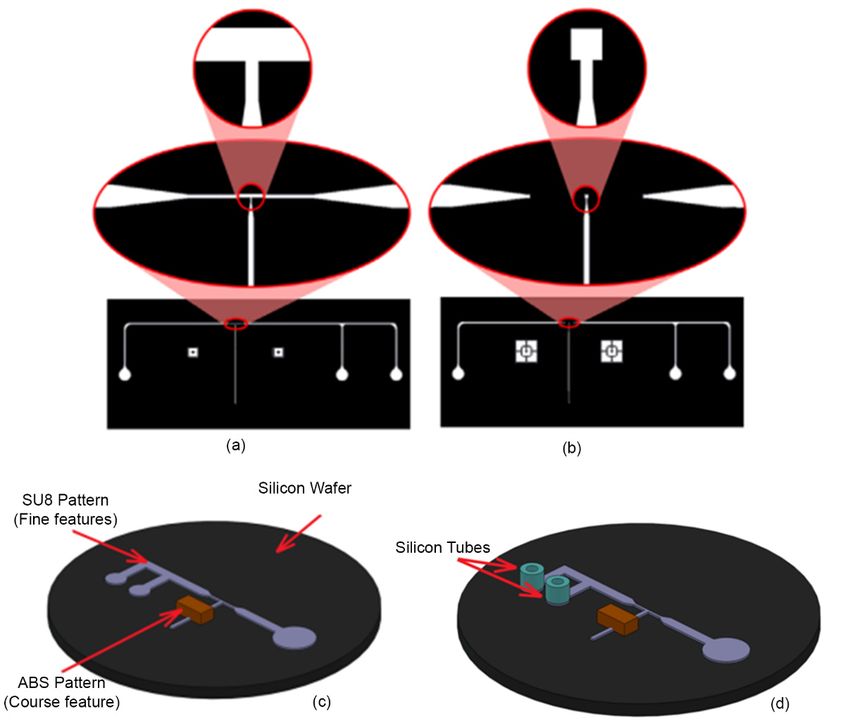
Micromachines 2020, 11, 295                                                                                          3 of 17

introduced into the device by pressurizing the syringe. The width and depth of loading channel was
defined to be 300 µm and 65 µm, respectively. The reservoir diameter was set as 3 mm and the inner
and outer diameter of the flexible tube (ID of 1/32” and OD of 3/32”) were chosen. To transfer the
 Micromachines
worms  to the2020, 11,ax3 mL syringe was selected which was controlled by a syringe pump.
               tube,                                                                           2 of 17

      Figure 1. Schematic of the five parts of the microinjector including a loading channel, immobilization
       Figure 1. Schematic of the five parts of the microinjector including a loading channel,
      mechanism, needle actuation mechanism, reagent delivery system and unloading channel.
       immobilization mechanism, needle actuation mechanism, reagent delivery system and unloading
       channel.
2.2. Immobilization  Channel

  2.1. An   immobilization
       Loading   System         mechanism was required to trap and immobilize the mobile young adult
C. elegans worm for needle insertion, after loading the worm into the device. To meet this need,
        A loading channel
an immobilization        channelwas    designedoftotwo
                                   consisting        transfer  the young
                                                         narrowed          adult
                                                                     portions  at C.theelegans  worms
                                                                                         beginning    and(with
                                                                                                            end the
                                                                                                                 (thelength
                                                                                                                       blue
  and   diameter    of  45  µm  and    1000 µm,   respectively   and  in-plane  sinusoidal      swimming
channels in Figure 2a,b), and one enlarged region at the middle of the immobilization channel (the             pattern  with
  the   amplitude    of   100   µm)    from  their  feeding   culture   plate  on    which
yellow channels between two narrowed channels in Figure 2a,b), was developed. The two narrowedthey  were     grown    to  the
  injection   zone.  To    do  this,  a loading   system   consisting   of a syringe,     flexible
channel has a depth and width of 25 µm and 55 µm, respectively. Meanwhile, the depth in the enlargedplastic   tube  and   the
  microchannels
region               on the microfluidic
          of the immobilization      channel,chip   was
                                               called  as designed
                                                          “injection (Figure  1). aInitially,
                                                                     area”, had      length ofthe  worms
                                                                                                 100 µm and  were   washed
                                                                                                                a depth   of
  and   transferred    from   the agar   plate  by  using  M9   buffer (3.0 g KH    2PO4, 6.0 g Na2HPO4, 0.5 g NaCl,
65 µm. The worm was loaded into the immobilization channel by application of a positive pressure
at1.0
    theg inlet
          NH4Cl   Bring
               using   thetosyringe
                              1 L with    H2O)Furthermore,
                                       pump.     into a syringe,duewhich   was attached
                                                                     to compression           to theofinlet
                                                                                          loading            of the in
                                                                                                        the worm     device.
                                                                                                                        the
  Next,   the  worms    were   introduced    into  the device   by pressurizing    the  syringe.   The
channel, the friction between the worm and the channel walls allow precise micrometer scale position     width   and  depth
ofofthe
     loading    channel
         worm2020,
Micromachines    axially   was defined to be 300 µm and 65 µm, respectively. The reservoir diameter
                    11, x along the channel so that the gonad of the worm can be aligned to the needle.
                                                                                                                         was
                                                                                                                     3 of 17
  set as 3 mm and the inner and outer diameter of the flexible tube (ID of 1/32” and OD of 3/32”) were
  chosen. To transfer the worms to the tube, a 3 mL syringe was selected which was controlled by a
  syringe pump.

 2.2. Immobilization Channel
       An immobilization mechanism was required to trap and immobilize the mobile young adult
  C.elegans worm for needle insertion, after loading the worm into the device. To meet this need, an
  immobilization channel consisting of two narrowed portions at the beginning and end (the blue
  channels in Figure 2a,b), and one enlarged region at the middle of the immobilization channel (the
  yellow channels between two narrowed channels in Figure 2a,b), was developed. The two
      Figure 2.
      Figure 2. (a,b)
                (a,b) The
                       The schematic design   ofofthe immobilization    system. The  narrowed  channel  hadhad
                                                                                                            25 µm
  narrowed    channel   hasschematic
                              a depth design
                                       and width    theofimmobilization
                                                          25 µm and 55system.     The   narrowed
                                                                            µm, respectively.     channel
                                                                                                Meanwhile,       25 depth
                                                                                                               the
      depth with   55 µm width.  The  depth  in the  middle   of the narrowed  channel  with length
      µm depth with 55 µm width. The depth in the middle of the narrowed channel with length of 100 of 100 µm  was
  in the enlarged region of the immobilization channel, called as “injection area”, had a length of 100
      increased
      µm         to 65 µm where
           was increased    to 65 called as “injection
                                   µm where       called area”.  (c) The microinjector
                                                           as “injection               channels
                                                                          area”. (c) The        composed
                                                                                           microinjector    of four
                                                                                                         channels
  µm and a depth of 65 µm. The worm was loaded into the immobilization channel by application of
      channels: Loading
      composed     of fourchannel,  needle
                             channels:      channel,
                                        Loading        immobilization
                                                     channel,    needle channel
                                                                         channel,and  unloading channel.
                                                                                   immobilization    channel and
  a positive pressure at the inlet using the syringe pump. Furthermore, due to compression loading of
      unloading channel.
  the worm in the channel, the friction between the worm and the channel walls allow precise
  micrometer scale position of the worm axially along the channel so that the gonad of the worm can
2.3. Needle Size
  be aligned to the needle.
      The function of needle tip is to create a passage through the tissue in which it is inserted. The
shape of the tip and its size (inner (ID) and outer diameter (OD) at the tip) play significant roles in
tissue-needle interaction and tissue damage. Needles with tip sizes in the range of 3 µm to 6 µm
were considered suitable to minimize tissue damage while being large enough to allow easy
delivery of reagents into cylindrical shape C. elegans worm with diameter of ~45 µm. Unlike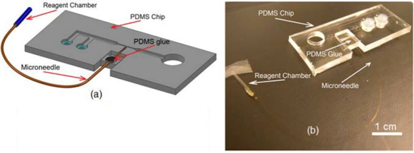
Micromachines 2020, 11, 295                                                                                                 4 of 17

2.3. Needle Size
     The function of needle tip is to create a passage through the tissue in which it is inserted. The shape
of the tip and its size (inner (ID) and outer diameter (OD) at the tip) play significant roles in tissue-needle
interaction and tissue damage. Needles with tip sizes in the range of 3 µm to 6 µm were considered
suitable to minimize tissue damage while being large enough to allow easy delivery of reagents
into cylindrical shape C. elegans worm with diameter of ~45 µm. Unlike conventional C. elegans
microinjection which uses capillaries with OD/ID of 1000/500 µm for needle fabrication, fused silica
microcapillaries with OD/ID of 90/20 µm were chosen for needle fabrication. This selection allows an
optimal fit and simple integration of the needle with microfluidic devices where the channel dimensions
are 50–100 µm, which was not possible with the needle used in conventional C. elegans microinjection.
To pull fused silica microcapillaries, a custom-built fused silica capillary pulling machine was designed
and built which allows to fabricate conical microneedle with tip sizes in the range of 3 µm to 6 µm.

2.4. Needle Actuation
     The goal of the microinjection is to inject biomolecules into the gonad of the worm, when it is
immobilized. The gonad of C. elegans worm is cylindrical in shape with the diameter and length of
20 µm and 200 µm, respectively. A simple single DOF complaint mechanism (as shown in Figure 3a,b)
was used in the place of conventional multiDOF micromanipulator to inject into the distal arm of the
gonad. The system was composed of three parts: a movable block, a fixed block and a thin flexible
membrane that connects the two blocks (see Figure 3a,b). The microneedle was attached to the movable
block and it could move relative to the fixed block inside the needle channel in a manner similar to
prismatic joints. When the movable block was pushed by a micropositioner (the displacement “D”
in Figure 3b), it deflects the flexible membrane and subsequently, moves the microneedle inside the
needle channel (the displacement “d” in Figure 3b). After unloading the movable block, the stored
potential energy in membrane (PDMS membrane was used as a spring) drives back the movable block
to the stationary
   Micromachines    point
                 2020, 11, x (similar to the condition in Figure 3a).                         4 of 17

     Figure  3. (a,b)
        Figure        TheThe
                 3. (a,b)  conceptual  design
                               conceptual     of theofcompliant
                                           design                  mechanism.
                                                        the compliant            (a) Before
                                                                          mechanism.         actuation.
                                                                                         (a) Before      (b) After
                                                                                                     actuation.    actuation.
                                                                                                                 (b) After
     Theactuation.
         motion ofThe themotion
                          micromanipulator     “D”   deflected    the  PDMS   membrane      subsequently
                                  of the micromanipulator “D” deflected the PDMS membrane subsequently      moved    “d” the
     needle
        movedinside
                 “d”thetheneedle
                            needlechannel
                                    inside in
                                           thefixed  block.
                                                needle        (c) This
                                                         channel         schematic
                                                                     in fixed  block.shows    how
                                                                                       (c) This     compliant
                                                                                                  schematic     mechanism
                                                                                                              shows   how
     wascompliant
          integrated   to loadingwas
                     mechanism     and integrated
                                        immobilization     mechanism.
                                                    to loading              The fixed block
                                                                   and immobilization          was extended
                                                                                           mechanism.          and loading
                                                                                                         The fixed   block
     andwas
         immobilization
             extended andchannel
                              loadingwere   created on it. (d)
                                       and immobilization         Bottomwere
                                                               channel      viewcreated
                                                                                  of the complaint    mechanism.
                                                                                          on it. (d) Bottom   view of(e)the
                                                                                                                         The
        complaint
     geometry        mechanism.
                of the             (e) TheThe
                        needle channel.     geometry
                                              thickness of of
                                                           thetheneedle
                                                                   channelchannel.  The thickness
                                                                             was uniformly     65 µm.of the channel was
        uniformly 65 µm.

   2.5. Reagent Chamber
        The design of the reagent delivery system is shown in Figure 4. It consists of a reagent chamber
   and microneedle. In conventional microinjection, the microneedle itself was used as reagent
   reservoir since the holding volume of the pulled microneedle (typically 50 mm in length and ID of
   0.5 mm) was ~9 µL which is larger than the total volume of the reagent required for a set of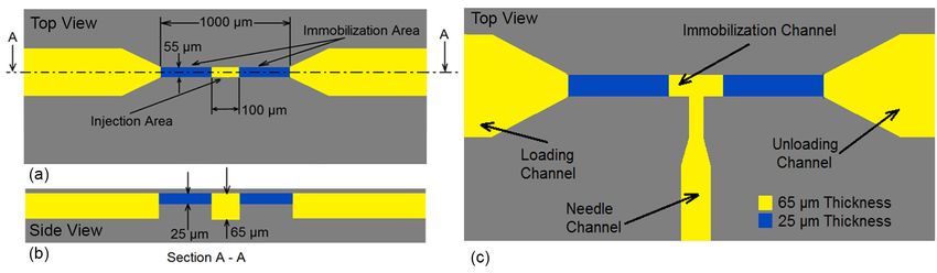
Micromachines 2020, 11, 295 5 of 17
In order to integrate the complaint mechanism with loading and immobilization system, the fixed
blockFigure
was extended and
3. (a,b) The the loading
conceptual andofimmobilization
design channel were
the compliant mechanism. integrated
(a) Before on it(b)
actuation. as shown
After in
Figure 3c. ThisThe
actuation. design allowed
motion of thethe needle to be well
micromanipulator “D”inserted into
deflected theimmobilization
PDMS membrane channel while its tip
subsequently
was centered
moved “d” with
theimmobilization
needle inside the channel. Since the
needle channel inouter
fixed diameter
block. (c) of theschematic
This shank of shows
the needle
how was
90 µm,compliant
it gentlymechanism
tapers downwas to
integrated to loading
the needle tip of 3and
to 6immobilization
µm, the dimension mechanism.
of theThe fixedchannel
needle block on
was extended
the fixed and loading
and the movable andwas
block immobilization
selected as channel
shown in were created
Figure on it. depth
3e (The (d) Bottom
of theview of the was
channels
complaint
65 µm). mechanism.
This ensured (e) The
that the geometry could
microneedle of the smoothly
needle channel.
moveThe thickness
in fixed blockofatthe
thechannel wasbeing
tip while
uniformly 65 µm.
tightly attached to the movable block.
2.5. Reagent Chamber
The design of the reagent delivery system is shown in Figure Figure 4.
4. It consists of a reagent chamber
microneedle.InInconventional
and microneedle. conventional microinjection,
microinjection, the microneedle
the microneedle itselfused
itself was wasas used
reagentasreservoir
reagent
reservoir
since since the
the holding holding
volume of volume
the pulled of microneedle
the pulled microneedle
(typically 50(typically
mm in length50 mm andinIDlength
of 0.5 and
mm)ID of
was
0.5µL
~9 mm)whichwasis ~9 µL than
larger whichtheistotal
larger thanofthe
volume thetotal
reagentvolume of the
required for areagent required for (usually
set of microinjection a set of
microinjection
~2 µL). However, (usually ~2 µL).
the holding However,
volume theneedle
of the holding
(with OD =of
volume 90the ID = 20
µm,needle (with
µm,OD = 90ofµm,
length ID =
80 mm)
20 µm,
used length
in this design of is80 mm) used
extremely smallin(~25
thisnL)design is extremely
and could small (~25
not accommodate all thenL) and needed
reagent could not
for
a set of injections. Therefore, the microneedle was connected to a larger glass capillary (ID = 0.5 mm,
accommodate all the reagent needed for a set of injections. Therefore, the microneedle was
OD = 1 mm,
connected larger=glass
to alength capillary
25 mm) (ID to
in order = 0.5 mm,
store theOD = 1 mm,
reagent length
during = 25 mm) in order
microinjection to store the
as schematically
reagentinduring
shown Figuremicroinjection
4. The reservoir as schematically
can be connected shown in Figure 4.toThe
subsequently reservoir
either can be source
to a pressure connected
for
subsequently to
pressure driven flow.either to a pressure source for pressure driven flow.
Figure 4. Schematic of the microneedle (OD = 90 µm, ID = 20 µm, length = 80 mm) connected to the
Figure 4. Schematic of the microneedle (OD = 90 µm, ID = 20 µm, length = 80 mm) connected to the
reagent chamber (ID = 0.5 (mm), OD = 1 (mm), length = 25 (mm)).
reagent chamber (ID = 0.5 (mm), OD = 1 (mm), length = 25 (mm)).
2.6. Worm Unloading and Plating
2.6. Worm Unloading and Plating
Once the reagent was delivered, the worm should be unloaded from the immobilization channel
Once on
and plated thestandard
reagent agar
was plate
delivered, the worm
for recovery. should
Towards be unloaded
this task, the outletfrom the was
reservoir immobilization
left open to
atmosphere by punching a hole such that there are no dead zones for accumulation of reservoir
channel and plated on standard agar plate for recovery. Towards this task, the outlet the worms was
as
left open to atmosphere by punching a hole such that there are no dead zones for accumulation
shown previously in Figure 1. When an individual worm was injected, the loading channel was closed of
the worms
and the worm as was
shown previously
manually in Figure
pushed out by 1. When
using an individual
a syringe connectedworm was
to the injected,
washing the loading
channel to the
open outlet reservoir. The open reservoir also allowed easy pick up of individual worms immediately
after injection by using a micropipette and then plate it on agar plate as shown in Figure 1. Then,
the injection cycle was repeated to another worm.
3. Device Fabrication
The fabrication of microinjector device is a multi-step process consisting of PDMS chip fabrication
using soft-lithography technique, fabrication of the compliant mechanism and final assembly of the
microneedle with the PDMS chip. The process flow for the device fabrication is shown in Figure 5.
First, the master mold was fabricated using combination of photolithography process and 3D printer
(Figure 5a–c). Next, interconnectors were placed on the master mold and PDMS prepolymer was cast
on it (Figure 5d,e). Subsequently, a microneedle was created using a custom-made needle puller and
prepared for reagent loading (Figure 5g,h). Then, the PDMS elastomeric chip was peeled of the mold
and it was assembled with microneedle. Finally, the chip was bonded to a glass slide (Figure 5f–k).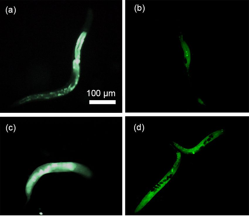
shown in Figure 5. First, the master mold was fabricated using combination of photolithography
process and 3D printer (Figure 5a–c). Next, interconnectors were placed on the master mold and
PDMS prepolymer was cast on it (Figure 5d,e). Subsequently, a microneedle was created using a
custom-made needle puller and prepared for reagent loading (Figure 5g,h). Then, the PDMS
elastomeric chip was peeled of the mold and it was assembled with microneedle. Finally, the chip
Micromachines 2020, 11, 295                                                               6 of 17
was bonded to a glass slide (Figure 5f–k).

     Figure 5. The process flow for device fabrication. (a) Pattering of the first SU8 layer with thickness of
      Figure 5. The process flow for device fabrication. (a) Pattering of the first SU8 layer with thickness of
     40 µm. (b) Pattering of the second SU8 layer with thickness of 25 µm on the first layer. (c) Attachment of
      40 µm. (b) Pattering of the second SU8 layer with thickness of 25 µm on the first layer. (c)
     the ABS part (thickness of 2 mm) created by 3D printer to fabricate a hybrid master mold. (d) Placement
      Attachment of the ABS part (thickness of 2 mm) created by 3D printer to fabricate a hybrid master
     of the interconnectors (silicone tubes) on SU8 pattern. (e) Casting of PDMS (1:10) on the mater mold to
      mold. (d) Placement of the interconnectors (silicone tubes) on SU8 pattern. (e) Casting of PDMS
     create a 3 mm device layer and 1mm PDMS membrane for compliant mechanism. (f) Peeling off of the
      (1:10) on the mater mold to create a 3 mm device layer and 1mm PDMS membrane for compliant
     PDMS substrate from the master mold. (g) Pulling of the microneedle from fused silica capillary and (h)
      mechanism. (f) Peeling off of the PDMS substrate from the master mold. (g) Pulling of the
     Connection of the microneedle to larger capillary to store the reagent. (i) Assembly of the microneedle
      microneedle from fused silica capillary and (h) Connection of the microneedle to larger capillary to
     and PDMS chip. (k) Bonding of the PDMS chip to the glass slide using dry oxygen bonding.
      store the reagent. (i) Assembly of the microneedle and PDMS chip. (k) Bonding of the PDMS chip to
      thebegin
     To   glass slide using drythe
                the process,     oxygen  bonding.
                                   first layer of the photomask (Figure 6a) was patterned on a 40 µm SU8
(SU-8-2075, Microchem Corp, Newton, MA, USA) that was spun on a silicon wafer (76 mm diameter,
University Wafer, South Boston, MA. USA). The same process was repeated to create the second layer
of the pattern (Figure 6b) over the first layer with a thickness of 25 µm. In order to create the features
related to compliant mechanism, an ABS block with the dimension of 3.5 × 3 mm2 base and 2 mm
height was 3D printed and attached to the SU8 structures on silicon wafer (at a distance of 1cm from
the immobilization channel) to create the final composite mold as shown in Figure 6c. A thin layer
(~50 µm) of 1:2 (PDMS to curing agent) PDMS pre polymer was used as the glue. Finally, the mold
was heated (75 ◦ C for 1h) to cure the PDMS. In order to have access to the inlet and washing channel,
silicone tubes with ID 1.5 mm and OD of 4.8 mm and 10 mm length were used. The tubes were placed
on the corresponding reservoirs on the SU8 mold (see in Figure 6c,d). This method allowed complete
integration of the interconnects with PDMS device with excellent sealing.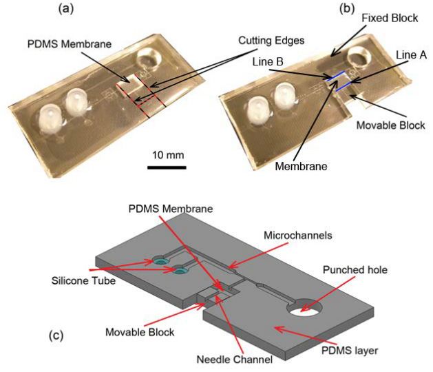
Figure 6c. A thin layer (~50 µm) of 1:2 (PDMS to curing agent) PDMS pre polymer was used as the
glue. Finally, the mold was heated (75 °C for 1h) to cure the PDMS. In order to have access to the
inlet and washing channel, silicone tubes with ID 1.5 mm and OD of 4.8 mm and 10 mm length
were used. The tubes were placed on the corresponding reservoirs on the SU8 mold (see in Figure
6c,d). This method allowed complete integration of the interconnects with PDMS device7 of
Micromachines 2020, 11, 295
with
17
excellent sealing.
Figure6.6. The
Figure The microchannel
microchannel pattern for (a) (a) the
thefirst
firstand
and(b)
(b)the
thesecond
secondlayer
layerofof
the microchannels.
the microchannels. (c)
The
(c) Themaster
mastermold
moldcomposed
composedofoftwo twotypes
types ofof molds (course and and fine
fine features).
features). The
TheSU8
SU8pattern
patternon on
Siliconwafer
Silicon waferdefined
defined the
the fine
fine features
features with
with resolution
resolution of µm
of 10 10 µm
andand the ABS
the ABS pattern
pattern usedused to create
to create the
the course
course features
features with minimum
with minimum resolution
resolution of 100of 100(d)
µm. µm.The(d) The master
master moldputting
mold after after putting silicon
silicon tubes
tubes
(ID (ID 1.5
1.5 mm mmOD
of and of of
and4.8ODmmofand4.810mmmmand 10 mm
length) length)
on the on the SU8
SU8 patterns patterns
in order in order
to have accesstoto have
the
inlet andtowashing
access the inletchannel after PDMS
and washing channel casting.
after PDMS casting.
The
Thenext step
next after
step mold
after fabrication
mold was PDMS
fabrication was PDMScasting. To do this,
casting. To do Polydimethylsiloxane (PDMS)
this, Polydimethylsiloxane
pre-polymer mixture (Sylgard
(PDMS) pre-polymer mixture184 kit, Dow
(Sylgard 184Corning
kit, DowCorp.,
Corning Midland,
Corp., MI, USA; 10:
Midland, MI,1USA;
ratio10:
of the baseof
1 ratio
and
the crosslinker) was cast on
base and crosslinker) wasthecast
master
on themold andmold
master curedand at room
curedtemperature for 24 h. The
at room temperature for 24volume
h. The
ofvolume
the dispended PDMS pre
of the dispended polymer
PDMS (25 mL) (25
pre polymer intomL)
10 cminto(diameter) Petri dish
10 cm (diameter) corresponded
Petri to an
dish corresponded
approximate thickness
to an approximate of 3 mm
thickness ofand
3 mm 1 mm andin1 the
mmPDMSin thechipPDMSandchipcompliant mechanism
and compliant section,
mechanism
respectively. Next, the Next,
section, respectively. PDMSthe elastomer was peeledwas
PDMS elastomer off from
peeled theoff
master
from mold, the extra
the master mold,PDMSthe was
extra
trimmed and the outlet chambers was punched out with a biopsy tool with
PDMS was trimmed and the outlet chambers was punched out with a biopsy tool with diameter of diameter of 8 mm. Then,
the PDMS
8 mm. substrate
Then, was cutsubstrate
the PDMS along thewasred lines as shown
cut along the in
redFigure
lines7aastoshown
make thein compliant
Figure 7a mechanism.
to make the
Incompliant
this configuration, the movable and fixed blocks were connected to the
mechanism. In this configuration, the movable and fixed blocks were connectedPDMS membrane via “Line
to the
A” and “Line
PDMS B” (blue
membrane lines),
via “Linerespectively
A” and “Line as shown in Figure
B” (blue 7b. respectively
lines), Usually, a small as amount
shown in of the PDMS
Figure 7b.
prepolymer seepsamount
Usually, a small into theofsilicone
the PDMS tubeprepolymer
during PDMS casting
seeps process
into the duetube
silicone to itsduring
low surface
PDMSenergy.
casting
Therefore, after curing and peeling off the PDMS, the insides of the interconnectors were punched
using a biopsy tool to open them.
The next step is the integration of the microneedle into the PDMS substrate. To do this, the
PDMS substrate was inverted and placed under optical microscope (10–20x Objective) such that the
microchannel features were accessible from the top for needle integration. Next, the microneedle was
gently placed on the PDMS substrate, positioned and aligned so that the tip of the microneedle was at
a distance of ~100 µm to 200 µm from the immobilization channel. Then, the shank of the microneedle
assembly was inserted into needle channel on the movable block as schematically shown in Figure 8a.
Since the size of the needle channel on the movable block was a good fit with the outer diameter of the
needle itself, it held the needle tightly at that location and prevented any further movement of the
needle during subsequent processes. Next, a droplet (~1 µL) of the PDMS pre polymer (4:1 ratio of the
base and crosslinker) was spread on the movable block to fully attach the microneedle to the movable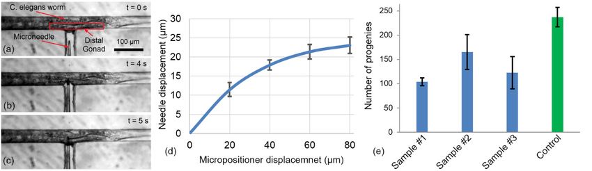
Micromachines 2020, 11, 295 8 of 17
Micromachines 2020, 11, x 7 of 17
block. After
process rapid
due to curing
its low the PDMS
surface energy.glue (see the black
Therefore, after dot on the
curing andmovable
peeling block
off theinPDMS,
Figure the
8a) insides
using a
flame, the PDMS chip was taken off from the microscope for bonding
of the interconnectors were punched using a biopsy tool to open them. (Figure 8b).
Figure 7. Steps and schematic of PDMS chip cutting and pouching (a) The PDMS chip after
trimming and pouching. (b) The PDMS chip after cutting and releasing the movable block. (c)
Schematic of different parts of the PDMS chip after casting.
The next step is the integration of the microneedle into the PDMS substrate. To do this, the
PDMS substrate was inverted and placed under optical microscope (10–20x Objective) such that the
microchannel features were accessible from the top for needle integration. Next, the microneedle
was gently placed on the PDMS substrate, positioned and aligned so that the tip of the microneedle
was at a distance of ~100 µm to 200 µm from the immobilization channel. Then, the shank of the
microneedle assembly was inserted into needle channel on the movable block as schematically
shown in Figure 8a. Since the size of the needle channel on the movable block was a good fit with
the outer diameter of the needle itself, it held the needle tightly at that location and prevented any
further movement of the needle during subsequent processes. Next, a droplet (~1 µL) of the PDMS
pre polymer (4:1 ratio of the base and crosslinker) was spread on the movable block to fully attach
the microneedle
Figure 7.
Figure to and
7. Steps
Steps the movable
andschematic
schematicblock.
of PDMS After
of PDMS rapid
chipchip
cuttingcuring thepouching
and pouching
cutting and PDMS glue
(a) The (see
PDMS
(a) theafter
Thechip
PDMS black dot
trimming
chip on the
after
movable block
and pouching.
trimming in Figure 8a)
(b) The PDMS
and pouching. using a flame,
chipPDMS
(b) The the PDMS
after cutting chip
and cutting
chip after was
releasing taken off
thereleasing
and movable the from
block. the microscope
(c) Schematic
movable of for
block. (c)
bonding (Figure
different
Schematic of 8b).
parts of the PDMS
different chip
parts of theafter
PDMS casting.
chip after casting.
The next step is the integration of the microneedle into the PDMS substrate. To do this, the
PDMS substrate was inverted and placed under optical microscope (10–20x Objective) such that the
microchannel features were accessible from the top for needle integration. Next, the microneedle
was gently placed on the PDMS substrate, positioned and aligned so that the tip of the microneedle
was at a distance of ~100 µm to 200 µm from the immobilization channel. Then, the shank of the
microneedle assembly was inserted into needle channel on the movable block as schematically
shown in Figure 8a. Since the size of the needle channel on the movable block was a good fit with
the outer diameter of the needle itself, it held the needle tightly at that location and prevented any
further movement of the needle during subsequent processes. Next, a droplet (~1 µL) of the PDMS
pre polymer (4:1 ratio of the base and crosslinker) was spread on the movable block to fully attach
Figure
Figure 88.(a)
the microneedle (a)Ato
Aschematic
the movable
schematic ofofthe
theneedle
block.
needle assembly
After processes
rapid
assembly and
curing the
processes different
andPDMS parts
glue
different of
of the
(see
parts the chip.
the black(b)
chip. dot
(b) The
on the
The
PDMS
movablePDMS chip
block after
chip in needle
Figure
after assembly.
needle8a) using a flame, the PDMS chip was taken off from the microscope for
assembly.
bonding (Figure 8b).
Bonding
Bondingwas wasthe thefinal
finalstep
stepininthe
thefabrication
fabricationofofthe
theinjection
injectiondevice.
device.The ThePDMS
PDMS substrate and
substrate anda
75 × 25
a 75 × 25mmmmglass
2 2 slide
glass slidewere
were exposed
exposedtoto5050WWoxygen
oxygenplasma
plasmafor for7070s.s.Since
Sincethetheplasma
plasma machine
machine
worked in low level of the pressure, the DI water present inside the reagent chamber
worked in low level of the pressure, the DI water present inside the reagent chamber when opening when opening
the tip evaporated. Therefore, after taking off the PDMS chip from the plasma machine, the reagent
chamber was filled with reagent that is required for microinjection. A thin layer of grease was
then spread on the movable block to reduce the friction of the motion during the needle actuation.
Afterwards, the PDMS chip was placed under microscope and a 10 mL syringe was connected to the
reagent chamber. By pressurizing the reagent chamber, the needle was tested for suitable operation
and clogging. If the needle was clogged, a sharp and clean scalpel was used to gentle touch the tip of
the microneedle which dislodges any residue accumulated at the tip and opens the microneedle. It is
important to be note that the force during the touching should not be high that it breaks the needle.
Finally, the8glass
Figure (a) Aslide was placed
schematic on theassembly
of the needle PDMS chip and the
processes and bonding process
different parts waschip.
of the completed
(b) The (see
Figure 9).
PDMS chip after needle assembly.
Bonding was the final step in the fabrication of the injection device. The PDMS substrate and a
75 × 25 mm2 glass slide were exposed to 50 W oxygen plasma for 70 s. Since the plasma machine
worked in low level of the pressure, the DI water present inside the reagent chamber when opening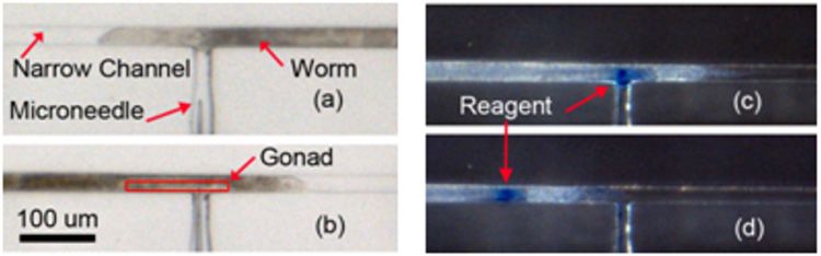
the reagent
the reagent chamber.
chamber. By By pressurizing
pressurizing thethe reagent
reagent chamber,
chamber, the
the needle
needle was
was tested
tested for
for suitable
suitable
operation and clogging. If the needle was clogged, a sharp and clean scalpel was
operation and clogging. If the needle was clogged, a sharp and clean scalpel was used to gentle used to gentle
touch the
touch the tip
tip of
of the
the microneedle
microneedle which
which dislodges
dislodges any
any residue
residue accumulated
accumulated atat the
the tip
tip and
and opens
opens the
the
microneedle. It is important to be note that the force during the touching should not be
microneedle. It is important to be note that the force during the touching should not be high that it high that it
breaks the
Micromachinesneedle.
2020, 11, Finally,
295 the glass slide was placed on the PDMS chip and the
breaks the needle. Finally, the glass slide was placed on the PDMS chip and the bonding process bonding process
9 of 17
was completed
was completed (see(see Figure
Figure 9)
9)
Figure
Figure999.(a)
Figure (a) AAschematic
(a)A schematic and
schematicand (b)
and(b) PDMS
(b)PDMS chip
PDMSchip ofoffinal
chipof final C.C.elegans
finalC. elegans microinjector
microinjector...
elegansmicroinjector
4. Experimental
4.Experimental
4. Setup
ExperimentalSetup
Setup
The
The experimental setup
The experimental
experimental setup(Figure
setup (Figure10)10)
(Figure 10) consisted
consisted
consisted of three
of three
of three
major major parts:
parts:parts:
major FluidicFluidic
system,
Fluidic system, optical
opticaloptical
system, system
system
and the and the microfluidic
microfluidic device. device.
The The
fluidic fluidic
system system
which which
was used was
to used
introduce
system and the microfluidic device. The fluidic system which was used to introduce the worms to introduce
the worms the worms
into the into
device
into
the device
anddevice
the and
deliverand deliver
reagents
deliver reagents
intoreagents
the worm, into
into the worm,
consisted
the worm, consisted of
of a pressurized
consisted ofair
aa tank
pressurized
at 4 (bar),
pressurized airpressure
air tank at
tank atregulator
44 (bar),
(bar),
pressure
(2000 regulator
Series (2000
Regulator, Series
ARO, Regulator,
Ingersoll Rand, ARO, Ingersoll
Bryan, OH, Rand,
USA) and Bryan,
a Ohio
solenoid
pressure regulator (2000 Series Regulator, ARO, Ingersoll Rand, Bryan, Ohio , USA) and a solenoid , USA)
valve and a solenoid
(S10MM-30-12-3,
valve
valve (S10MM-30-12-3,
3-Way(S10MM-30-12-3,
Normally Closed,3-Way3-Way
Pneumadyne, Normally
Normally Closed,
Inc., Plymouth,
Closed, Pneumadyne,
MN, USA).Inc.,
Pneumadyne, Inc., Plymouth,
The Plymouth,
optical systemMN,
MN, USA).
that was used
USA). The
The
optical
optical system
to observe,
system that was
control
that was record
and used to
used totheobserve,
injection
observe, control
process
control and
and record the
consisted
record the
of an injection process
opticalprocess
injection microscope consisted
(Model
consisted of 500
of an
an
optical microscope
LumaScope, (Model
Etaluma, Inc., 500 LumaScope,
Carlsbad, CA, Etaluma,
USA), digitalInc, Carlsbad,
camera (Flea3 CA, USA), digital
FLs-U3-32S2C, ® Systems,
camera
FLIR (Flea3
optical microscope (Model 500 LumaScope, Etaluma, Inc, Carlsbad, CA, USA), digital camera (Flea3
FLs-U3-32S2C, FLIR®
Inc., Pittsburgh,FLIR®
FLs-U3-32S2C, PA, USA)Systems,
and software
Systems, Inc. (Labview©
Inc. ,, Pittsburgh,
Pittsburgh, PA, USA) and
, flyCapture2
PA, USA) and©software
software (Labview
software,(Labview ©, flyCapture2
Version ©2.13.3.61,
, flyCapture2FLIR©©®
software,
software, Version
Systems, Inc.,
Version 2.13.3.61,
Pittsburgh,
2.13.3.61, FLIR®
PA,FLIR® Systems,
USA). Systems, Inc. ,, Pittsburgh,
The microfluidic
Inc. Pittsburgh,
device, which PA,was
PA, USA).
used
USA). The
The microfluidic
to microfluidic
perform device,
the injection
device,
which
into C. was used
elegans to
worm, perform
consisted the of injection
a into
microinjector C. elegans
chip worm,
(whose consisted
fabrication
which was used to perform the injection into C. elegans worm, consisted of a microinjector chip wasof a microinjector
described in chip
previous
(whose
chapter)
(whose fabrication was described
described(Micrometer
and a micropositioner
fabrication was in previous
in previous chapter)
chapter)
fine focus and
and aa micropositioner
linearmicropositioner
stage, Model A (Micrometer
LHFF, Linefine
(Micrometer fine
Tool focus
Co.,
focus
linear stage,
Allentown, Model
PA, USA).A LHFF, Line Tool Co., Allentown,
linear stage, Model A LHFF, Line Tool Co., Allentown, PA, USA). PA, USA).
Figure ExperimentalSetup
10. Experimental
Figure 10.
Figure Experimental Setupused
Setup used
used for
forfor C. elegans
C. C. elegans
elegans microinjection
microinjection consisted
consisted
microinjection of major
of three
consisted of three major
three major Fluidic
parts: parts:
parts:
Fluidic system,
system,system,
Fluidic optical
optical optical system
systemsystem and microchip.
and microchip.
and microchip.
The micropositioner
The
The micropositioner attached
micropositioner attachedto
attached tothe
to themovable
the movable
movable block
block
blockonon
microfluidic
on chip
microfluidic
microfluidic (see(see
chip
chip Figure
(see 9b) was
Figure
Figure 9b) used
9b) was
was
to
usedaccurately
to move
accurately the microneedle
move the with
microneedle resolution
with of 5 µm.
resolution The
of 5air
µm.pressure
The tank
air
used to accurately move the microneedle with resolution of 5 µm. The air pressure tank was was
pressureconnected
tank to
was
the reagent chamber on microinjector chip through a pressure regulator and a solenoid
connected to the reagent chamber on microinjector chip through a pressure regulator and aa
connected to the reagent chamber on microinjector chip through a pressure valve
regulatorand.
andThis
system allows
solenoid
solenoid valveone
valve to This
and.
and. generate an adjustable
This system
system allows one
allows pressure
one pulse for
to generate
to generate anreagent
an delivery.
adjustable
adjustable The solenoid
pressure
pressure forvalve
pulse for
pulse was
reagent
reagent
used to control the duration and number of the pulses for each individual injection. The microfluidic
injector was installed under optical microscope (Light Microscope, Leica, Concord, ON, Canada) and a
CMOS camera mounted on it was used to record the video of the injection processes. After injection, a
200 µL micropipette was used to transfer the injected worms into the standard nematode growth (NG)
agar plates for recover after injection.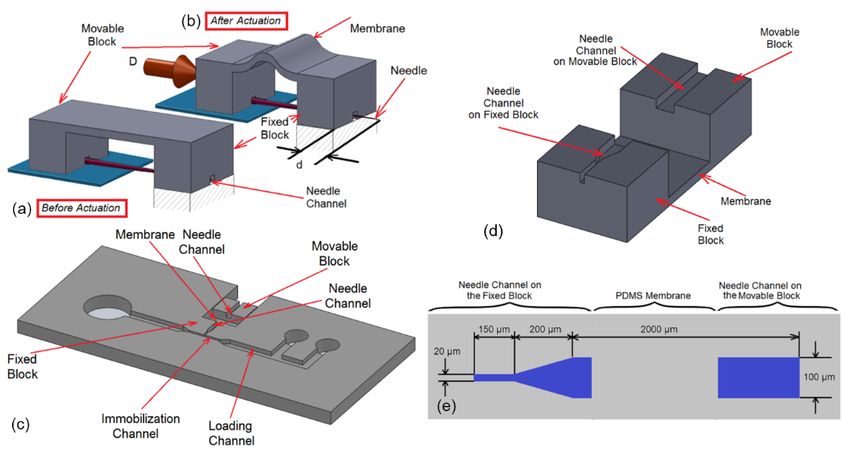
delivery. The solenoid valve was used to control the duration and number of the pulses for each
individual injection. The microfluidic injector was installed under optical microscope (Light
Microscope, Leica, Concord, ON, Canada) and a CMOS camera mounted on it was used to record
the video of the injection processes. After injection, a 200 µL micropipette was used to transfer the
injected worms
Micromachines 2020, into the standard nematode growth (NG) agar plates for recover after injection.10 of 17
11, 295
5. Results and Discussion
5. Results and Discussion
5.1. Characterization of the Immobilization System
5.1. Characterization of the Immobilization System
To immobilize the worm, first, the wild-type N2 C. elegans worms was moved into the mouth
of theTonarrowing
immobilizeregion
the worm,
of thefirst,
immobilization N2 C. elegans
the wild-typechannel worms channel
via loading was moved into the
(Figure 11b)mouth of the
by using a
narrowing region of the immobilization channel via loading channel (Figure
constant pressure on the syringe. Then, the pressure was applied to push the worm into the 11b) by using a constant
pressure on the channel
immobilization syringe. (Figure
Then, the pressure
11c). The wormwas applied to push the
was compressed on worm intovia
the sides theaimmobilization
two narrowed
channel (Figure
channel with the11c).
depthTheand
worm wasofcompressed
width 25 µm andon 55the
µm,sides via a two The
respectively. narrowed
enlargedchannel with
region the
of the
depth and width of 25 µm and 55 µm, respectively. The enlarged region of the
immobilization channel, called as “injection area”, had a length of 100 µm and a depth of 65 µmimmobilization channel,
called
(see as “injection
Figure area”, had a length
11a). Subsequently, of 100 µm
the position of theandworm
a depth of 65channel
in the µm (seeand Figure 11a). Subsequently,
its alignment with the
the position of the worm in the channel and its alignment with the position
position of the needle channel was adjusted by inserting (Figure 11d) or withdrawing (Figure of the needle channel
11e)
was adjusted by inserting (Figure 11d) or withdrawing (Figure 11e) the plunger
the plunger in the syringe as appropriate. The narrowed portions of the immobilization channel in the syringe as
appropriate.
would allow The
easynarrowed portions
visualization of the
of the immobilization
internal organs as channel
well as would allow easyimmobilization;
allow consistent visualization of
while the enlarged region at the center which is connected to the needle channel,atwill
the internal organs as well as allow consistent immobilization; while the enlarged region the center
allow
which is connected to the needle channel,
centered injection as shown in Figure 11f. will allow centered injection as shown in Figure 11f.
Figure 11. (a) A Aschematic
schematicofofthe theimmobilization
immobilization channel.
channel. The
Thenarrowed
narrowed channel
channel hadhad
25 µm 25 depth
µm depthwith
55 µm55width.
with The depth
µm width. The in the middle
depth in the of the narrowed
middle channel with
of the narrowed length
channel of 100
with µm was
length increased
of 100 µm was to
65 µm where
increased to 65called as “injection
µm where called area”. (b–e) image
as “injection area”.sequence
(b–e) imageof worm loading
sequence process.
of worm (b) The
loading worm
process.
wasThe
(b) introduced
worm was intointroduced
the immobilization channel, (c) thechannel,
into the immobilization worm was (c) pushed
the worm intowas
thepushed
immobilization
into the
channel, (d) the worm was fully inserted into the immobilization channel
immobilization channel, (d) the worm was fully inserted into the immobilization channel and (e) theand (e) the distal gonad of
the worm was aligned with needle channel for needle insertion. (f) an immobilized
distal gonad of the worm was aligned with needle channel for needle insertion. (f) an immobilized C. elegans worm
inside
C. the final
elegans worm design.
insideThethepicture shows that
final design. Thethe narrowed
picture showsportions
that the of the immobilization
narrowed portionschannel
of the
would allow easychannel
immobilization visualization
wouldofallowthe internal organs as wellof
easy visualization as the
allow consistent
internal organsimmobilization.
as well as (g) At
allow
the loading pressure less than 50 (kPa), the worms could not be fully inserted
consistent immobilization. (g) At the loading pressure less than 50 (kPa), the worms could not be into immobilization
channel.
fully Wheninto
inserted 50 (kPa) pressure was
immobilization appliedWhen
channel. on the50worms, only 1/3rd
(kPa) pressure of the
was length
applied onofthe
theworms,
worm couldonly
1/3rd of the length of the worm could be compressed into narrowed channel and the rest of(h)
be compressed into narrowed channel and the rest of worm was remained in loading channel. The
worm
loading
was time versus
remained the loading
in loading pressure.
channel. t = 120 time
(h) TheAtloading s, theversus
worm thewasloading
not fullypressure.
loaded and = 0 s,
At tat=t120 s, the
the
worm was not captured in the immobilization channel. (i) Viability of the worms
worm was not fully loaded and at t = 0 s, the worm was not captured in the immobilization channel. after immobilization.
Worms
(i) (n =of5 the
Viability for worms
each plate)
afterreproduction
immobilization. rateWorms
72 h after
(n = 55 min immobilization
for each compared
plate) reproduction rateto72not
h
immobilized control animals.
after 5 min immobilization compared to not immobilized control animals.
For a certain defined immobilization channel (25 µm depth and 55 µm width here), the required
time to introduce and align the worms (relative to the needle) into the immobilization channel was
dependent on the applied pressure. In order to characterize the required pressure with loading time,
constant pressure in range of 50–200 kPa was applied inside the loading channel to load the worm in
the immobilization channel. Subsequently, the immobilization process (Figure 11b–e) was observedMicromachines 2020, 11, 295 11 of 17
and recorded from which the required loading time was calculated. The result of the experiment,
loading time versus the loading pressure, has been plotted in Figure 11h. The results showed that at
50 kPa loading pressure or below, the worms could not be fully inserted into immobilization channel.
When 50 kPa pressure was applied on the worms, only 1/3rd of the length of the worm could be
compressed into narrowed channel and the rest of worm was remained in the loading channel as
shown in Figure 11g. The experiment was performed on 5 worms and after 120 s, the worms could not
be inserted more than 1/3rd of its length.
In the immobilization process, there are two forces acting on the worm. One is the force due
to pressure that pushes the worm through the narrow channel. The other is the frictional force on
the worm’s body. The fiction force is dependent to the length of the worm, inserted into the channel.
At low pressures (Micromachines 2020, 11, x 11 of 17
the micropositioner was characterized by applying a known displacement to the micropositioner
and measuring
Micromachines the295
2020, 11, actual movement of the microneedle tip. The needle motion was recorded12under of 17
microscope and then, the videos were analyzed to obtain needle displacement by using a custom
image processing procedure. The plot in Figure 12d shows the displacement applied by the
(x-axis) and the resultant
micropositioner needle
(x-axis) and the motion
resultantasneedle
measuredmotion through image analysis
as measured through(y-axis). Since the
image analysis (y-
initial position of the needle was not the same for all the devices, the needle position
axis). Since the initial position of the needle was not the same for all the devices, the needle position was normalized
to thenormalized
was original position. It can beposition.
to the original seen that It the
can microneedle
be seen that can the be moved in can
microneedle a controllable
be moved and in a
repeatable manner by using a micropositioner and a compliant mechanism.
controllable and repeatable manner by using a micropositioner and a compliant mechanism. The The relationship between
the displacement
relationship of thethe
between needle tip and that
displacement of the
of the micropositioner
needle tip and that of is the
not micropositioner
linear. This mayisbenotbecause
linear.
the
This may be because the stiffness of the micropositioner was not constant and varied with the
stiffness of the micropositioner was not constant and varied with the displacement. Similar to the
conventional
displacement.microinjection,
Similar to the the conventional
depth of the injection can be controlled
microinjection, the depthbyofoperator in this device.
the injection can be
An insertionby
controlled depth of about
operator 5–25device.
in this µm from Antheinsertion
body wall of theofworm
depth aboutis 5–25
generally aimedthe
µm from forbody
to achieve
wall ofa
successful injection. A marker for successful injection into the gonad would be the
the worm is generally aimed for to achieve a successful injection. A marker for successful injection physical expansion
of thethe
into gonad
gonadwhenwouldthe pressure pulse isexpansion
be the physical applied. In of the
the cases
gonadwhere
whensuch an expansion
the pressure pulseisismanifested
applied. In
the
thedelivered
cases wherereagents
suchhave remained in
an expansion is the gonad. An
manifested theunsuccessful injection have
delivered reagents leads remained
to spread ofin the
the
reagents into other body parts, notably the gut. Therefore, according the characteristics
gonad. An unsuccessful injection leads to spread of the reagents into other body parts, notably the shown in in
Figure 12d, the compliant system designed in this platform is capable to perform
gut. Therefore, according the characteristics shown in in Figure 12d, the compliant system designed accurate needle
insertion into theisgonad.
in this platform capable to perform accurate needle insertion into the gonad.
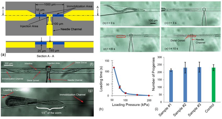
Figure12.
Figure 12. (a–c)
(a–c) image
imagesequence
sequenceofofthe needle
the insertion,
needle (a) (a)
insertion, the the
microneedle was was
microneedle aligned with with
aligned distal
gonadgonad
distal of theof worm,
the worm, (b) (b)
thethe
microneedle
microneedlewaswas moved
movedand andpenetrated
penetratedinto
into the
the worm, (c) (c) the
the
microneedlewas
microneedle was inserted
inserted intogonad
into the the and
gonad and for
suitable suitable for delivery.
the reagent the reagent delivery.
(d) The (d) The
characterization
ofcharacterization
the compliant mechanism. A known
of the compliant displacement
mechanism. has been
A known applied to has
displacement the micropositioner
been applied toand the
measuring the movement
micropositioner of the microneedle
and measuring the movementwas calculated using images
of the microneedle wasofcalculated
the tip of the microneedle.
using images of
The
the experiment has been repeated
tip of the microneedle. for 8 timeshas
The experiment on been
one device.
repeatedThefor minimum
8 times onresolution
one device.of the
The
micropositioner
minimum resolution was 20 ofµm. (e) Viability test was
the micropositioner of the20worms
µm. (e)after needletest
Viability insertion. (n =needle
Wormsafter
of the worms 5 for
each plate) Worms
insertion. reproduction
(n = 5 rate 72 h plate)
for each after needle insertion
reproduction compared
rate toneedle
72 h after not inserted control
insertion worms.to not
compared
inserted control worms.
In order to study the effect of the combination of immobilization and injection on the viability
and reproduction rate ofthe
In order to study theeffect
worms, a set
of the of experiment
combination was performed,and
of immobilization as described
injection onbelow. Young
the viability
adult Wild-type N2rate
and reproduction C. elegans worms (n
of the worms, = 15)
a set of were immobilized
experiment into narrowed
was performed, channelbelow.
as described and then the
Young
microneedle
adult Wild-type was inserted into the
N2 C. elegans gonad
worms (n for 2 s were
= 15) and then removed.into
immobilized Subsequently, the worms
narrowed channel andwere
then
unloaded and plated
the microneedle wastoinserted
examineintothe effect of the for
the gonad microneedle
2 s and theninsertion and the
removed. ensuing tissue
Subsequently, thedamage
worms
on the unloaded
were viability andandreproduction.
plated to examine the effect of the microneedle insertion and the ensuing tissue
The results
damage (see Figure
on the viability and12c) demonstrated that number of the progenies for the injected worms
reproduction.
were significantly (p-value < 0.00001)
The results (see Figure 12c) demonstratedreduced (105–165
that numberprogenies) comparedfor
of the progenies to the
the control
injectedworms
worms
(238
were progenies) due (p-value
significantly to the effect of immobilization
< 0.00001) and injection
reduced (105–165 (the error
progenies) bar in Figure
compared 12c shows
to the control wormsthe
standard deviation from three sample that were taken to count the number of the
(238 progenies) due to the effect of immobilization and injection (the error bar in Figure 12c showsprogenies). Since the
immobilization alone does
the standard deviation notthree
from causesample
any significant
that were difference
taken to in the number
count the numberof progenies, it can be
of the progenies).
concluded
Since the that the needle insertion
immobilization alone and
doesthenot ensuing
causetissue
any damage cause
significant the reduction
difference in thein the number
number of
ofprogenies,
progeniesitproduced by the worms. This decrease in the number of progenies was
can be concluded that the needle insertion and the ensuing tissue damage cause the similar to the case
of other microinjection
reduction in the number procedures for C. produced
of progenies elegans whereby thethe progeny size isdecrease
worms. This reducedin to the
10–50%
numberof theof
normal brood size. Observation of the worms post injection on agar plate
progenies was similar to the case of other microinjection procedures for C.elegans where the showed that the worms
were able to
progeny sizerecover normaltomotion
is reduced 10–50% andofwerethe indistinguishable
normal brood size. from the wild type
Observation of within 24 h after
the worms post
needle insertion.You can also read