Multi Eco Installation/Operating Manual - Centrifugal Pump - KSB Web-Shop
←
→
Page content transcription
If your browser does not render page correctly, please read the page content below

Centrifugal Pump

Multi Eco
Multi Eco
Multi Eco-Pro
Multi Eco-Top

Installation/Operating Manual
Legal information/Copyright
Installation/Operating Manual Multi Eco

Original operating manual

All rights reserved. The contents provided herein must neither be distributed, copied, reproduced,
edited or processed for any other purpose, nor otherwise transmitted, published or made available to a
third party without the manufacturer's express written consent.
Subject to technical modification without prior notice.

© KSB SE & Co. KGaA, Frankenthal 09/04/2019
Contents

                                        Contents
    Glossary .................................................................................................................................................. 5
1   General.................................................................................................................................................... 6
    1.1    Principles ...........................................................................................................................................................   6
    1.2    Installation of partly completed machinery....................................................................................................                           6
    1.3    Target group.....................................................................................................................................................        6
    1.4    Other applicable documents............................................................................................................................                   6
    1.5    Symbols .............................................................................................................................................................    6
    1.6    Key to safety symbols/markings.......................................................................................................................                    7

2   Safety ...................................................................................................................................................... 8
    2.1    General.............................................................................................................................................................. 8
    2.2    Intended use ..................................................................................................................................................... 8
    2.3    Personnel qualification and training............................................................................................................... 8
    2.4    Consequences and risks caused by non-compliance with this manual ......................................................... 9
    2.5    Safety awareness .............................................................................................................................................. 9
    2.6    Safety information for the operator/user ....................................................................................................... 9
    2.7    Safety information for maintenance, inspection and installation ................................................................ 9
    2.8    Unauthorised modes of operation ................................................................................................................ 10

3   Transport/Temporary Storage/Disposal............................................................................................. 11
    3.1    Checking the condition upon delivery ..........................................................................................................                         11
    3.2    Transport.........................................................................................................................................................      11
    3.3    Storage/preservation ......................................................................................................................................             11
    3.4    Return to supplier...........................................................................................................................................           13
    3.5    Disposal ...........................................................................................................................................................    13

4   Description of the Pump (Set) ............................................................................................................. 14
    4.1    General description ........................................................................................................................................            14
    4.2    Designation.....................................................................................................................................................        14
    4.3    Name plate......................................................................................................................................................        14
    4.4    Design details..................................................................................................................................................        14
    4.5    Configuration and function...........................................................................................................................                   15
    4.6    Scope of supply...............................................................................................................................................          17
    4.7    Dimensions and weights ................................................................................................................................                 18
    4.8    Noise characteristics .......................................................................................................................................           19

5   Installation at Site ................................................................................................................................ 20
    5.1    Safety regulations...........................................................................................................................................           20
    5.2    Checks to be carried out prior to installation...............................................................................................                           21
    5.3    Installing the pump set ..................................................................................................................................              21
    5.4    Piping ..............................................................................................................................................................   21
           5.4.1 Connecting the piping.......................................................................................................................                      21
    5.5    Protective equipment.....................................................................................................................................               27
           5.5.1 Overload protection device...............................................................................................................                         27
           5.5.2 Protection against overheating ........................................................................................................                           27
    5.6    Electrical system..............................................................................................................................................         27
           5.6.1 Electrical connection..........................................................................................................................                   27
    5.7    Checking the direction of rotation................................................................................................................                      28

6   Commissioning/Start-up/Shutdown................................................................................................... 30
    6.1    Commissioning/Start-up .................................................................................................................................                30
           6.1.1 Prerequisites for commissioning/start-up .........................................................................................                                30
           6.1.2 Priming the pump ..............................................................................................................................                   30
           6.1.3 Opening a consumer installation......................................................................................................                             31
           6.1.4 Setting the start-up und stop pressures (Multi Eco Top only).........................................................                                             31
           6.1.5 Start-up...............................................................................................................................................           32

                                        Multi Eco                                                                                                                        3 of 60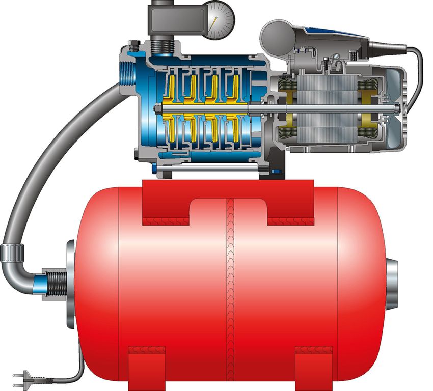
Contents
6.1.6 Shutdown ........................................................................................................................................... 33
6.2 Operating limits.............................................................................................................................................. 33
6.2.1 Ambient temperature........................................................................................................................ 33
6.2.2 Maximum operating pressure ........................................................................................................... 33
6.2.3 Fluid handled ..................................................................................................................................... 34
6.3 Shutdown/storage/preservation .................................................................................................................... 34
6.4 Returning to service ....................................................................................................................................... 35
7 Servicing/Maintenance ........................................................................................................................ 36
7.1 Safety regulations........................................................................................................................................... 36
7.2 Drainage/cleaning .......................................................................................................................................... 37
7.3 Inspection work .............................................................................................................................................. 37
7.3.1 Cleaning the suction strainer ............................................................................................................ 37
7.3.2 Checking the pre-charge pressure of the accumulator (Multi Eco Top only) ................................ 37
7.3.3 Checking the automatic devices for starting and stopping the pump........................................... 37
7.4 Dismantling the pump set.............................................................................................................................. 38
7.4.1 General information/Safety regulations........................................................................................... 38
7.4.2 Preparing the pump set..................................................................................................................... 38
7.4.3 Removing the complete pump set from the piping ........................................................................ 38
7.4.4 Removing the stage casings .............................................................................................................. 39
7.4.5 Removing the mechanical seal and rolling element bearings ........................................................ 41
7.4.6 General information/Safety regulations........................................................................................... 42
7.4.7 Fitting the rolling element bearings and the mechanical seal ....................................................... 43
7.4.8 Fitting the stage casings .................................................................................................................... 46
7.5 Reassembling the pump set ........................................................................................................................... 49
7.6 Spare parts stock............................................................................................................................................. 49
7.6.1 Ordering spare parts.......................................................................................................................... 49
7.6.2 Recommended spare parts stock for 2 years' operation to DIN 24296 .......................................... 49
8 Trouble-shooting.................................................................................................................................. 50
9 Related Documents .............................................................................................................................. 51
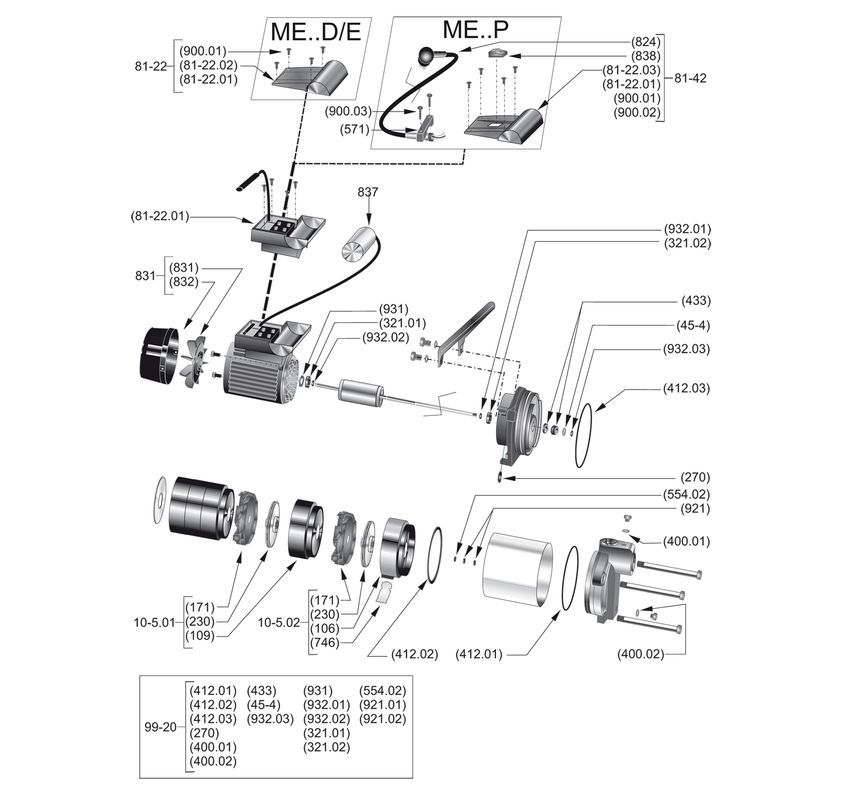
9.1 Exploded view and list of components ......................................................................................................... 51
9.2 Installation example ....................................................................................................................................... 52
9.2.1 Multi Eco-Pro...................................................................................................................................... 52
9.2.2 Multi Eco Top ..................................................................................................................................... 53
9.3 Dimensions...................................................................................................................................................... 53
10 EU Declaration of Conformity ............................................................................................................. 56
11 EU Declaration of Conformity ............................................................................................................. 57
12 Certificate of Decontamination........................................................................................................... 58
Index ..................................................................................................................................................... 59
4 of 60 Multi Eco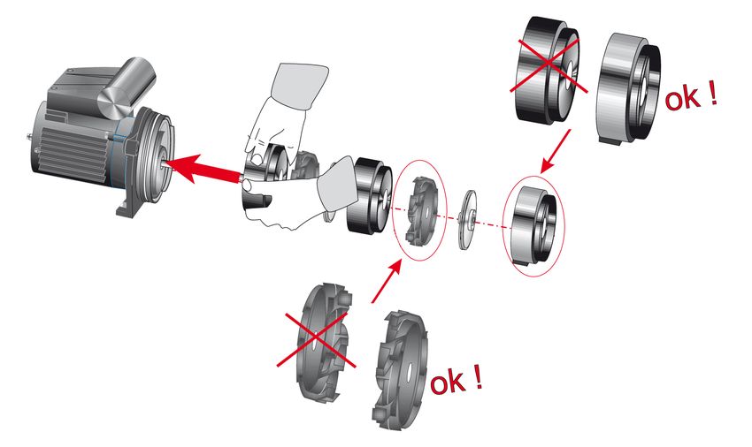
Glossary

                               Glossary

Certificate of decontamination
     A certificate of decontamination is enclosed by the
     customer when returning the product to the
     manufacturer to certify that the product has been
     properly drained to eliminate any environmental
     and health hazards arising from components in
     contact with the fluid handled.

Close-coupled design
     Motor directly fitted to the pump via a flange or a
     drive lantern

Pump
     Machine without drive, additional components or
     accessories

Pump set
     Complete pump set consisting of pump, drive,
     additional components and accessories

Self-priming ability
     Ability of a filled pump to evacuate a suction line,
     i.e. to self-prime from an unfilled suction line.

Suction lift line/suction head line
     The pipeline which is connected to the suction
     nozzle

                               Multi Eco                    5 of 60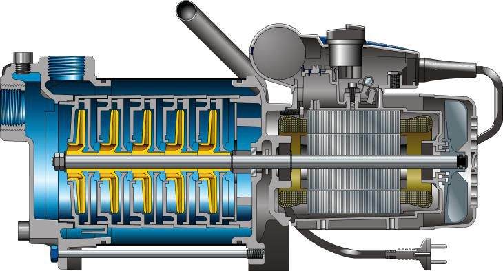
1 General

                                 1 General

                                 1.1 Principles
                                 This operating manual is valid for the type series and variants indicated on the front
                                 cover.
                                 The operating manual describes the proper and safe use of this equipment in all
                                 phases of operation.
                                 The name plate indicates the type series and size, the main operating data, the order
                                 number and the order item number. The order number and order item number
                                 clearly identify the pump set and serve as identification for all further business
                                 processes.
                                 In the event of damage, immediately contact your nearest KSBservice facility to
                                 maintain the right to claim under warranty.

                                 1.2 Installation of partly completed machinery
                                 To install partly completed machinery supplied by KSB refer to the sub-sections under
                                 Servicing/Maintenance.

                                 1.3 Target group
                                 This operating manual is aimed at the target group of trained and qualified specialist
                                 technical personnel. (ð Section 2.3, Page 8)

                                 1.4 Other applicable documents
                                 Table 1: Overview of other applicable documents
                                  Document                                 Contents
                                  Data sheet                               Description of the technical data of the pump (set)
                                  General arrangement drawing/             Description of mating and installation dimensions
                                  outline drawing                          for the pump (set), weights
                                  Hydraulic characteristic curve           Characteristic curves showing head, NPSHrequired,
                                                                           efficiency and power input
                                  General assembly drawing1)               Sectional drawing of the pump
                                  Sub-supplier product literature1)        Operating manuals and other product literature
                                                                           describing accessories and integrated machinery
                                                                           components
                                  Spare parts lists1)                      Description of spare parts
                                                 1)
                                  Piping layout                            Description of auxiliary piping
                                  List of components1)                     Description of all pump components
                                 For accessories and/or integrated machinery components, observe the relevant
                                 manufacturer's product literature.

                                 1.5 Symbols
                                 Table 2: Symbols used in this manual
                                  Symbol                Description
                                          ✓             Conditions which need to be fulfilled before proceeding with the
                                                        step-by-step instructions
                                           ⊳            Safety instructions
                                          ⇨             Result of an action
                                          ⇨             Cross-references

1)    If agreed to be included in the scope of supply

6 of 60                          Multi Eco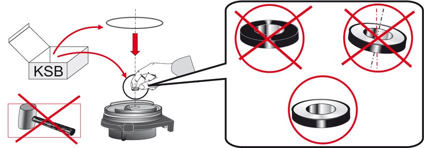
1 General

Symbol           Description
        1.       Step-by-step instructions
        2.
                 Note
                 Recommendations and important information on how to handle
                 the product

1.6 Key to safety symbols/markings
Table 3: Definition of safety symbols/markings
Symbol           Description
  !    DANGER    DANGER
                 This signal word indicates a high-risk hazard which, if not avoided,
                 will result in death or serious injury.
  !   WARNING    WARNING
                 This signal word indicates a medium-risk hazard which, if not
                 avoided, could result in death or serious injury.
      CAUTION    CAUTION
                 This signal word indicates a hazard which, if not avoided, could
                 result in damage to the machine and its functions.
                 Explosion protection
                 This symbol identifies information about avoiding explosions in
                 potentially explosive atmospheres in accordance with EU Directive
                 2014/34/EU (ATEX).
                 General hazard
                 In conjunction with one of the signal words this symbol indicates a
                 hazard which will or could result in death or serious injury.

                 Electrical hazard
                 In conjunction with one of the signal words this symbol indicates a
                 hazard involving electrical voltage and identifies information about
                 protection against electrical voltage.
                 Machine damage
                 In conjunction with the signal word CAUTION this symbol indicates
                 a hazard for the machine and its functions.

Multi Eco                                                                        7 of 60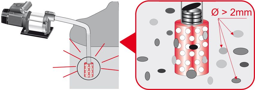
2 Safety

               2 Safety
               All the information contained in this section refers to hazardous situations.
  !   DANGER
               In addition to the present general safety information the action-related safety
               information given in the other sections must be observed.

               2.1 General
                ▪ This operating manual contains general installation, operating and maintenance
                  instructions that must be observed to ensure safe operation of the system and
                  prevent personal injury and damage to property.
                ▪ Comply with all the safety instructions given in the individual sections of this
                  operating manual.
                ▪ The operating manual must be read and understood by the responsible specialist
                  personnel/operators prior to installation and commissioning.
                ▪ The contents of this operating manual must be available to the specialist
                  personnel at the site at all times.
                ▪ Information and markings attached directly to the product must always be
                  complied with and kept in a perfectly legible condition at all times. This applies
                  to, for example:
                    – Arrow indicating the direction of rotation
                    – Markings for connections
                    – Name plate
                ▪ The operator is responsible for ensuring compliance with all local regulations not
                  taken into account.

               2.2 Intended use
                ▪ The pump (set) must only be operated in the fields of application and within the
                  use limits specified in the other applicable documents.
                ▪ Only operate pumps/pump sets which are in perfect technical condition.
                ▪ Do not operate the pump (set) in partially assembled condition.
                ▪ Only use the pump to handle the fluids described in the data sheet or product
                  literature of the pump model or variant.
                ▪ Never operate the pump without the fluid to be handled.
                ▪ Observe the minimum flow rates indicated in the data sheet or product literature
                  (to prevent overheating, bearing damage, etc).
                ▪ Observe the minimum flow rate and maximum flow rate indicated in the data
                  sheet or product literature (to prevent overheating, mechanical seal damage,
                  cavitation damage, bearing damage, etc).
                ▪ Do not throttle the flow rate on the suction side of the pump (to prevent
                  cavitation damage).
                ▪ Consult the manufacturer about any use or mode of operation not described in
                  the data sheet or product literature.

               2.3 Personnel qualification and training
               All personnel involved must be fully qualified to transport, install, operate, maintain
               and inspect the machinery this manual refers to.
               The responsibilities, competence and supervision of all personnel involved in
               transport, installation, operation, maintenance and inspection must be clearly
               defined by the operator.
               Deficits in knowledge must be rectified by means of training and instruction
               provided by sufficiently trained specialist personnel. If required, the operator can
               commission the manufacturer/supplier to train the personnel.
               Training on the pump (set) must always be supervised by technical specialist
               personnel.

8 of 60        Multi Eco
2 Safety

2.4 Consequences and risks caused by non-compliance with this manual
 ▪ Non-compliance with these operating instructions will lead to forfeiture of
   warranty cover and of any and all rights to claims for damages.
 ▪ Non-compliance can, for example, have the following consequences:
     – Hazards to persons due to electrical, thermal, mechanical and chemical
       effects and explosions
     – Failure of important product functions
     – Failure of prescribed maintenance and servicing practices
     – Hazard to the environment due to leakage of hazardous substances

2.5 Safety awareness
In addition to the safety information contained in this operating manual and the
intended use, the following safety regulations shall be complied with:
 ▪ Accident prevention, health regulations and safety regulations
 ▪ Explosion protection regulations
 ▪ Safety regulations for handling hazardous substances
 ▪ Applicable standards, directives and laws

2.6 Safety information for the operator/user
 ▪ Fit protective equipment (e.g. contact guards) supplied by the operator for hot,
   cold or moving parts, and check that the equipment functions properly.
 ▪ Do not remove any protective equipment (e.g. contact guards) during operation.
 ▪ Provide the personnel with protective equipment and make sure it is used.
 ▪ Contain leakages (e.g. at the shaft seal) of hazardous fluids handled (e.g.
   explosive, toxic, hot) so as to avoid any danger to persons and the environment.
   Adhere to all relevant laws.
 ▪ Eliminate all electrical hazards. (In this respect refer to the applicable national
   safety regulations and/or regulations issued by the local energy supply
   companies.)
 ▪ If shutting down the pump does not increase potential risk, fit an emergency-
   stop control device in the immediate vicinity of the pump (set) during pump set
   installation.

2.7 Safety information for maintenance, inspection and installation
 ▪ Modifications or alterations of the pump (set) are only permitted with the
   manufacturer's prior consent.
 ▪ Use only original spare parts or parts/components authorised by the
   manufacturer. The use of other parts/components can invalidate any liability of
   the manufacturer for resulting damage.
 ▪ The operator ensures that maintenance, inspection and installation are
   performed by authorised, qualified specialist personnel who are thoroughly
   familiar with the manual.
 ▪ Only carry out work on the pump (set) during standstill of the pump.
 ▪ Only perform work on the pump set when it has been disconnected from the
   power supply (de-energised).
 ▪ The pump (set) must have cooled down to ambient temperature.
 ▪ Pump pressure must have been released and the pump must have been drained.

Multi Eco                                                                         9 of 60
2 Safety

            ▪ When taking the pump set out of service always adhere to the procedure
              described in the manual.
            ▪ Decontaminate pumps which handle fluids posing a health hazard.
            ▪ As soon as the work has been completed, re-install and re-activate any safety-
              relevant devices and protective devices. Before returning the product to service,
              observe all instructions on commissioning. (ð Section 6.1, Page 30)

           2.8 Unauthorised modes of operation
           Never operate the pump (set) outside the limits stated in the data sheet and in this
           manual.
           The warranty relating to the operating reliability and safety of the supplied pump
           (set) is only valid if the equipment is used in accordance with its intended use.
           (ð Section 2.2, Page 8)

10 of 60   Multi Eco
3 Transport/Temporary Storage/Disposal
3 Transport/Temporary Storage/Disposal
3.1 Checking the condition upon delivery
1. On transfer of goods, check each packaging unit for damage.
2. In the event of in-transit damage, assess the exact damage, document it and
notify KSB or the supplying dealer and the insurer about the damage in writing
immediately.
3.2 Transport
DANGER
The pump (set) could slip out of the suspension arrangement
Danger to life from falling parts!
▷ Always transport the pump (set) in the specified position.
▷ Never attach the suspension arrangement to the free shaft end or the motor
eyebolt.
▷ Observe the information about weights, centre of gravity and fastening points.
▷ Observe the applicable local accident prevention regulations.
▷ Use suitable, permitted lifting accessories, e.g. self-tightening lifting tongs.
CAUTION
Improper pump transport
Damage to the pump!
▷ Never suspend the pump/pump set from the power cable.
▷ Prevent the pump (set) from getting knocked or dropped.
To transport the pump/pump set suspend it from the lifting tackle as shown.
Multi Eco Multi Eco-Pro Multi Eco-Top
3.3 Storage/preservation
If commissioning is to take place some time after delivery, we recommend that the
following measures be taken for pump (set) storage.
Multi Eco 11 of 603 Transport/Temporary Storage/Disposal
The pump set remains installed
1. Properly shut down the pump set.
CAUTION
Damage during storage due to frost, humidity, dirt, UV radiation or vermin
Corrosion/contamination of the pump!
▷ Store the pump (set) in a dry, dark, frost-proof room not exposed to sunlight
where the atmospheric humidity is as constant as possible.
2. Properly cover the pump set.
The pump set is removed from the system
1. Properly shut down the pump set.
2. Remove the suction and discharge lines from the pump.
WARNING
Fluids posing a health hazard
Hazard to persons and the environment!
▷ Collect and properly dispose of flushing liquid and any residues of the fluid
handled.
▷ Wear safety clothing and a protective mask, if required.
▷ Observe all legal regulations on the disposal of substances posing a health
hazard.
3. Drain the pump as per operating instructions.
4. Do not kink the power cables.
12 of 60 Multi Eco3 Transport/Temporary Storage/Disposal
5. Spray-coat any open connections with paraffin oil.
6. Store the pump (set) in a dry, dark, frost-proof room not exposed to sunlight
where the atmospheric humidity is as constant as possible.
3.4 Return to supplier
1. Drain the pump as per operating instructions. (ð Section 7.2, Page 37)
2. Flush and clean the pump, particularly if it has been used for handling noxious,
explosive, hot or other hazardous fluids.
3. If the pump has handled fluids whose residues could lead to corrosion damage
in the presence of atmospheric humidity or could ignite upon contact with
oxygen also neutralise the pump and blow through with anhydrous inert gas to
ensure drying.
4. Always complete and enclose a certificate of decontamination when returning
the pump.
Indicate any safety measures and decontamination measures taken.
(ð Section 12, Page 58)
NOTE
If required, a blank certificate of decontamination can be downloaded from the
following web site: www.ksb.com/certificate_of_decontamination
3.5 Disposal
WARNING
Fluids handled, consumables and supplies which are hot and/or pose a health
hazard
Hazard to persons and the environment!
▷ Collect and properly dispose of flushing fluid and any fluid residues.
▷ Wear safety clothing and a protective mask if required.
▷ Observe all legal regulations on the disposal of fluids posing a health hazard.
1. Dismantle the pump (set).
Collect greases and other lubricants during dismantling.
2. Separate and sort the pump materials, e.g. by:
- Metals
- Plastics
- Electronic waste
- Greases and other lubricants
3. Dispose of materials in accordance with local regulations or in another
controlled manner.
Multi Eco 13 of 604 Description of the Pump (Set)
4 Description of the Pump (Set)
4.1 General description
▪ Centrifugal pump
▪ Self-priming
▪ Multistage
▪ Clean to turbid water not containing aggressive, abrasive or solid substances
4.2 Designation
Example: Multi Eco-Top 35 E / 50
Table 4: Designation key
Code Description
Multi Eco-Top Type series
35 Size
E D Three-phase asynchronous motor
E Single-phase AC motor
50 Total volume of collecting tank [litres]
4.3 Name plate
1
7
2
8
3
KSB SAS
3 F-59 320 Sequedin
000000
Multi Eco 35.6 P 2014w38 9
4 220-240 V~ 3.7 A
50 Hz Classe F 10
5 800 W Hmax = 45 m
00027
C=12 µF / 450 V
IP44
LWA 59 dB
MADE IN FRANCE 2014 40982846
11
6
Fig. 1: Name plate (example)
1 Type series, size 2 Voltage
3 Nominal frequency 4 Nominal power
5 Capacitor capacity 6 Enclosure
7 Series code 8 Nominal current
9 Thermal class 10 Maximum head
11 Sound power [dB]
4.4 Design details
Design
▪ Centrifugal pump
▪ Close-coupled design
▪ Multistage
▪ Self-priming
Drive
Single-phase AC motor:
▪ Range of rated voltage: 220 - 240 V
▪ Frequency 50 Hz
▪ Thermal overload protection
14 of 60 Multi Eco4 Description of the Pump (Set)
Three-phase motor:
▪ Range of rated voltage: 380 - 415 V
▪ Frequency 50 Hz
▪ Enclosure IP44
▪ Thermal class F
Bearings
▪ Deep groove ball bearings
▪ Grease-lubricated for life
Multi Eco-Pro ▪ Multi Eco pump set
▪ Controlmatic E automatic control unit with glass-fibre reinforced polyamide
housing and integrated pressure gauge, with power cables for pump and mains
connection
or
▪ Controlmatic E.2 automatic control unit with glass-fibre reinforced polyamide
housing and integrated pressure gauge, with power cables for pump and mains
connection
Multi Eco-Top ▪ Multi Eco pump set
▪ Membrane-type accumulator, pressurised at the factory
▪ Metal-braided hose between pump and accumulator
▪ Pressure switch for automatic operation, factory-set
4.5 Configuration and function
Design Multistage, self-priming pump in close-coupled design with axial fluid inlet and
vertical fluid outlet.
The hydraulic system runs in common bearings and is connected to the motor via a
shaft.
Sealing The pump is sealed by a standardised mechanical seal. A thrower protects the
bearing and the motor in the event of leakage.
Multi Eco 15 of 604 Description of the Pump (Set)
Multi Eco
1 2 3 4
5 6 7
Fig. 2: Sectional drawing of Multi Eco
1 Suction nozzle 2 Discharge nozzle
3 Shaft 4 Shaft seal
5 Impellers 6 Diffusers
7 Discharge cover
Function of The fluid enters the pump via the suction nozzle (1) and is accelerated outward by
Multi Eco the rotating impellers (5). In the flow passage of the diffusers (6) and the pump
casing the kinetic energy of the fluid is converted into pressure energy. The fluid is
pumped to the discharge nozzle (2), where it leaves the pump. At the rear side of the
impeller, the shaft (3) enters the casing via the discharge cover (7). The shaft passage
is sealed by a shaft seal (4). The shaft runs in rolling element bearings.
Multi Eco-Pro
2 2
1 1
Fig. 3: Sectional drawing of Multi Eco-Pro
1 Pump 2 Pressure gauge
Function of The Controlmatic E.2 automatic control unit is used to start and stop the pump (1) in
Multi Eco-Pro line with consumer demand. Pressure is indicated by a pressure gauge (2).
16 of 60 Multi Eco4 Description of the Pump (Set)
Phase No. 1:
When the consumer installation is closed, the pump is stopped. The green "Power"
indicator lamp of Controlmatic E.2 is lit.
Phase No. 2:
When the consumer installation is opened, the water pressure in the system
decreases. The pump is started up.
Phase No. 3:
The pump is running, the yellow "On" indicator lamp is lit.
Phase No. 4:
When the consumer installation has been closed and the flow rate is zero, the pump
is stopped after 10 seconds. The pump is protected from dry running by simultaneous
pressure and flow monitoring. If there is a lack of water, Controlmatic E.2 stops the
pump and the red indicator lamp is lit.
Multi Eco-Top
3
1
2
Fig. 4: Sectional drawing of Multi Eco-Top
1 Pump 2 Membrane-type accumulator
3 Pressure gauge
Function of When the system pressure drops, the pump (1) is automatically started via the
Multi Eco-Top pressure switch (3). When the required pressure has been reached, the pump is
stopped automatically.
The membrane-type accumulator (2) serves to limit the frequency of pump starts by
providing smaller amounts of water from the volume stored.
4.6 Scope of supply
Depending on the model, the following items are included in the scope of supply:
▪ Pump
▪ Drive
Multi Eco E and D:
▪ Multi Eco pump set
▪ Without power cable (connected via motor's terminal strip)
Multi Eco P:
▪ Multi Eco pump set
▪ Power cable (length: 1.5 m) and CEE plug (2 phases + earth conductor)
▪ Handle
Multi Eco 17 of 604 Description of the Pump (Set)
Multi Eco-Pro:
▪ Multi Eco pump set
▪ Power cable (length: 1.5 m) and CEE plug (2 phases + earth conductor)
▪ Automatic control unit
Multi Eco-Top:
▪ Multi Eco pump set
▪ With single-phase AC motor (sizes 36 and 65 also available with three-phase
motor)
▪ Membrane-type accumulator, pressurised at the factory
▪ Pressure switch for automatic operation, factory-set
4.7 Dimensions and weights
Dimensions For pump set dimensions refer to (ð Section 9.3, Page 53) .
Weights Table 5: Multi Eco D weights
Size Weight
[kg]
Multi Eco 33 D 11
Multi Eco 34 D 11
Multi Eco 35 D 11
Multi Eco 36 D 12
Multi Eco 65 D 12
Table 6: Multi Eco E, P weights
Size Weight
[kg]
Multi Eco 33 E; P 11
Multi Eco 34 E; P 11
Multi Eco 35 E; P 11
Multi Eco 36 E; P 14
Multi Eco 65 E; P 14
Table 7: Multi Eco-Pro weights
Size Weight
[kg]
Multi Eco-Pro 34 13
Multi Eco-Pro 35 13
Multi Eco-Pro 36 16
Multi Eco-Pro 65 16
Table 8: Multi Eco-Top weights
Size Weight
[kg]
Multi Eco-Top 34 E 20 19
Multi Eco-Top 35 E 20 19
Multi Eco-Top 35 E 50 21
Multi Eco-Top 36 E 50 24
Multi Eco-Top 65 E 50 24
Multi Eco-Top 36 D 50 24
Multi Eco-Top 65 D 50 24
18 of 60 Multi Eco4 Description of the Pump (Set)
4.8 Noise characteristics
Table 9: Surface sound pressure level LwA
Size Noise characteristic
[dB]
Multi Eco 33 55
Multi Eco 34 55
Multi Eco 35 59
Multi Eco 36 67
Multi Eco 65 67
Multi Eco 19 of 605 Installation at Site
5 Installation at Site
5.1 Safety regulations
DANGER
Unsuitable electrical installation
Danger to life!
▷ Make sure the electrical installation meets the VDE 0100 and IEC 60364
installation rules (i.e. sockets with earthing terminals).
▷ Make sure the electric mains is equipped with a residual current device of
maximum 30 mA.
▷ If in doubt, contact a specialist electrical company.
DANGER
Use in an outdoor area
Danger of death from electric shock!
▷ The pump set must be installed at a distance of at least 3 metres from the fluid
reservoir.
▷ Do not expose electrical connections to any moisture.
▷ Any extension cord must match the quality of the supplied cable.
▷ Verify that all sealing elements at the pump's terminal box are properly fitted.
DANGER
Electrical connection work by unqualified personnel
Danger of death from electric shock!
▷ Always have the electrical connections installed by a trained and qualified
electrician.
▷ Observe regulations IEC 60364.
DANGER
Using damaged power cables
Danger of death from electric shock!
▷ Never connect any damaged power cables.
▷ Visually inspect the power cable before connecting it.
▷ Replace the power cable if it is damaged.
DANGER
Damaged terminal box
Danger of death from electric shock!
▷ Never operate a pump with a damaged terminal box.
WARNING
Excessive operating pressure
Fluid spurting out and parts flying off as a result of components bursting!
▷ If the pump is to be installed in pressurised piping, fit a pressure reducer
upstream of the pump.
20 of 60 Multi Eco5 Installation at Site
5.2 Checks to be carried out prior to installation
Place of installation
WARNING
Installation on mounting surface which is unsecured and cannot support the load
Personal injury and damage to property!
▷ Use a concrete of compressive strength class C12/15 which meets the
requirements of exposure class XC1 to EN 206-1.
▷ The mounting surface must be set, flat, and level.
▷ Observe the weights indicated.
1. Check the structural requirements.
All structural work required must have been prepared in accordance with the
dimensions stated in the outline drawing/general arrangement drawing.
5.3 Installing the pump set
WARNING
Excessive temperatures due to improper installation
Burns from touching hot surfaces!
Damage to the pump set!
▷ Install the pump set at distance of at least 30 mm from the wall in a dry, well-
ventilated room that is not at risk of flooding.
ü The place of installation has been properly prepared. (ð Section 5.2, Page 21)
1. Place the pump set in horizontal position.
2. Bolt down the feet of the pump set or membrane-type accumulator (Multi Eco-
Top).
(Except transportable version of Multi Eco)
5.4 Piping
5.4.1 Connecting the piping
WARNING
Impermissible loads acting on the pump nozzles
Burns from contact with fluid handled!
Damage to the pump set!
▷ Do not use the pump as an anchorage point for the piping.
▷ Anchor the pipes in close proximity to the pump casing.
▷ Observe the permissible forces and moments at the pump nozzles.
Multi Eco 21 of 605 Installation at Site
Connecting the suction line
ü Use a special suction line of at least the same nominal diameter as the pump's
suction nozzle.
ü A sand filter is connected to the suction line.
(The suction strainer must have a mesh size of more than 2 mm. For fluids
containing sand (max. 50 g/m³) the suction strainer must have a mesh size of less
22 of 60 Multi Eco5 Installation at Site
than 1 mm!)
NOTE
KSB offers G1" and G11/4" sand filters for installation on the suction side of the
pump. They can be ordered from specialist suppliers.
Multi Eco 23 of 605 Installation at Site
ü The suction lift line has been laid with a rising slope towards the pump, without
high point.
ü The piping has been anchored in close proximity to the pump and connected
without transmitting any stresses or strains, so that no impermissible loads act on
the suction nozzle.
1. Fit a swing check valve into the piping (Multi Eco Top/Pro: mandatory; Multi Eco
Pro: recommended).
The swing check valve is not included in the scope of supply.
2. If required, install a filter in the piping.
NOTE
Use a filter with laid-in wire mesh (mesh width 0.5 mm, wire diameter 0.25 mm) of
corrosion-resistant material.
Use a filter with a filter area three times the cross-section of the piping.
Conical filters have proved suitable.
3. Seal the suction line connection with Teflon tape.
24 of 60 Multi Eco5 Installation at Site
4. Screw the connection fitting into the pump.
(Screw plastic fittings in by hand.)
(Tighten metal connection fittings to a tightening torque of 100 Nm with a
wrench.)
5. Slide the suction line onto the connection fitting and fasten with a clamp.
Multi Eco 25 of 605 Installation at Site
Connecting the discharge line
ü The nominal diameter of the discharge line must be at least equal to the nominal
diameter of the pump's discharge nozzle.
1. Seal the discharge line connection with Teflon tape.
2. Screw the connection fitting into the pump.
(Screw plastic fittings in by hand.)
(Screw in metal connection fittings with a wrench (tightening torque: 100 Nm)).
3. Slide the discharge line onto the connection fitting and fasten with a clamp.
26 of 60 Multi Eco5 Installation at Site
5.5 Protective equipment
5.5.1 Overload protection device
CAUTION
Motor overload
Damage to the motor!
▷ Protect the motor by a thermal time-lag overload protection device in
accordance with IEC 60947 and local regulations.
1. Set the overload protection device to the rated motor current.
(ð Section 4.3, Page 14)
5.5.2 Protection against overheating
WARNING
Motor overheating due to poor ventilation
Burns from touching hot surfaces!
Damage to the pump set!
▷ Never cover the ventilation opening.
▷ Install the pump set at distance of at least 30 mm from the wall in a dry, well-
ventilated room.
▪ The single-phase motors of Multi Eco pump sets are equipped with a thermal
overload protection device with automatic reset and start-up.
▪ The three-phase motors of Multi Eco pump sets are not equipped with a thermal
overload protection device.
NOTE
KSB recommends that pump sets without thermal overload protection should be
connected via a thermal protective switch.
5.6 Electrical system
5.6.1 Electrical connection
DANGER
Electrical connection work by unqualified personnel
Danger of death from electric shock!
▷ Always have the electrical connections installed by a trained and qualified
electrician.
▷ Observe regulations IEC 60364.
WARNING
Incorrect connection to the mains
Damage to the mains network, short circuit!
▷ Observe the technical specifications of the local energy supply companies.
1. Check the available mains voltage against the data sheet.
2. Select an appropriate start-up method.
Multi Eco 27 of 605 Installation at Site
3. Remove terminal box cover 81-22.
4. Connect the pump set in accordance with the wiring diagram in the terminal
box cover.
5. Verify that the terminal box gasket has been properly fitted.
6. Close terminal box cover 81-22.
NOTE
A motor protection device is recommended.
5.7 Checking the direction of rotation
WARNING
Temperature increase caused by rotating parts
Risk of injuries! Damage to the pump set!
▷ Never check the direction of rotation by starting up the unfilled pump set.
WARNING
Hands inside the pump casing
Risk of injuries, damage to the pump!
▷ Always disconnect the pump set from the power supply and secure it against
unintentional start-up before inserting your hands or other objects into the
pump.
28 of 60 Multi Eco5 Installation at Site
CAUTION
Drive and pump running in the wrong direction of rotation
Damage to the pump!
▷ Observe the arrow indicating the direction of rotation on the pump's name
plate.
▷ Check the direction of rotation. If required, check the electrical connection and
correct the direction of rotation.
1. Start the motor and stop it again immediately to determine the motor's
direction of rotation.
2. Check the direction of rotation.
The motor's direction of rotation must match the arrow indicating the direction
of rotation on the pump's name plate.
3. If the motor runs in the wrong direction of rotation, check the electrical
connection of the motor and the control system, if applicable.
Multi Eco 29 of 606 Commissioning/Start-up/Shutdown
6 Commissioning/Start-up/Shutdown
6.1 Commissioning/Start-up
6.1.1 Prerequisites for commissioning/start-up
Before commissioning/starting up the pump set, make sure that the following
conditions are met:
▪ The pump set has been properly connected to the electric power supply and is
equipped with all protection devices.
▪ The pump has been primed with the fluid to be handled.
▪ The direction of rotation has been checked.
▪ All auxiliary connections required are connected and operational.
▪ After prolonged shutdown of the pump (set), the activities described in
(ð Section 6.4, Page 35) have been carried out.
6.1.2 Priming the pump
1. Unscrew the filler screw.
2. Fill in the fluid to be handled (min. 1.8 l)
3. Screw the filler screw back in and tighten to a torque of 10 Nm (max.).
30 of 60 Multi Eco6 Commissioning/Start-up/Shutdown 6.1.3 Opening a consumer installation 1. Open a consumer installation. 6.1.4 Setting the start-up und stop pressures (Multi Eco Top only) 1. Set start-up pressure P1. Fig. 5: Setting start-up pressure P1 2. Set differential pressure P. Fig. 6: Pressure control P1 Start-up pressure of pump P2 Stop pressure of pump ΔP Differential pressure Multi Eco 31 of 60
6 Commissioning/Start-up/Shutdown

           6.1.5 Start-up

                 DANGER
            Non-compliance with the permissible pressure and temperature limits if the pump
            is operated with the suction and discharge lines closed.
            Leakage of hot or toxic fluids!
              ▷ Never operate the pump with the shut-off elements in the suction line and/or
                discharge line closed.
              ▷ Only start up the pump set with the discharge-side gate valve slightly or fully
                open.

             CAUTION
            Excessive temperatures due to dry running or excessive gas content in the fluid
            handled
            Damage to the pump set!
              ▷ Never operate the pump set without liquid fill.
              ▷ Prime the pump as per operating instructions.
              ▷ Always operate the pump within the permissible operating range.

             CAUTION
            Abnormal noises, vibrations, temperatures or leakage
            Damage to the pump!
              ▷ Switch off the pump (set) immediately.
              ▷ Eliminate the causes before returning the pump set to service.

             1. Plug the mains plug into the mains socket.

             2. Switch on the pump set. (Multi Eco P)

32 of 60   Multi Eco
6 Commissioning/Start-up/Shutdown 6.1.6 Shutdown 1. Switch off the pump set. 2. Pull the mains plug out of the socket. 6.2 Operating limits 6.2.1 Ambient temperature CAUTION Operation outside the permissible ambient temperature Damage to the pump (set)! ▷ Observe the specified limits for permissible ambient temperatures. Observe the following parameters and values during operation: Table 10: Permissible ambient temperatures Permissible ambient temperature Value Maximum 50 °C Minimum See data sheet 6.2.2 Maximum operating pressure CAUTION Permissible operating pressure exceeded Damage to connections and seals! ▷ Never exceed the operating pressure specified in the data sheet. Table 11: Maximum operating pressure Size Maximum operating pressure Multi Eco 33, 34 6 bar Multi Eco 35, 36, 65 10 bar Multi Eco 33 of 60
6 Commissioning/Start-up/Shutdown

           6.2.3 Fluid handled

           6.2.3.1 Temperature of the fluid handled

             CAUTION
            Incorrect temperature of the fluid handled
            Damage to the pump (set)!
              ▷ Do not operate the pump (set) outside the specified temperature limits.

           Do not operate the pump at temperatures higher than 50°C.

           6.2.3.2 Minimum/maximum fluid level

             CAUTION
            Fluid level below the specified minimum
            Damage to the pump set by cavitation!
              ▷ Never allow the fluid level to drop below the specified minimum.

           6.3 Shutdown/storage/preservation

                 DANGER
            Electrical connection work by unqualified personnel
            Danger of death from electric shock!
              ▷ Always have the electrical connections installed by a trained and qualified
                electrician.
              ▷ Observe regulations IEC 60364.

                 DANGER
            Power supply not disconnected
            Danger to life!
              ▷ Pull the mains plug or disconnect all electrical connections and secure against
                unintentional start-up.

           The pump (set) remains installed
            ü Sufficient fluid is supplied for the functional check run of the pump.
             1. For prolonged shutdown periods, start up the pump (set) regularly between
                once a month and once every three months for approximately five minutes.
                ð This will prevent the formation of deposits within the pump and the pump
                  intake area.

           The pump (set) is removed from the pipe and stored
            ü The pump has been properly drained.
            ü The safety instructions for dismantling the pump have been observed.
             1. Spray-coat the inside wall of the pump casing and, in particular, the impeller
                clearance areas with a preservative.
             2. Spray the preservative through the suction nozzle and discharge nozzle.
                It is advisable to then close the pump nozzles (e.g. with plastic caps).
             3. Oil or grease all exposed machined parts and surfaces of the pump (with
                silicone-free oil or grease, food-approved if required) to protect them against
                corrosion.
                Observe the additional instructions on preservation.

34 of 60   Multi Eco
6 Commissioning/Start-up/Shutdown
If the pump set is to be stored temporarily, only preserve the wetted components
made of low-alloy materials. Commercially available preservatives (food-approved, if
required) can be used for this purpose. Observe the manufacturer's instructions for
application/removal.
Observe any additional instructions and information provided. (ð Section 3, Page 11)
6.4 Returning to service
For returning the equipment to service observe the sections on commissioning/start-
up and the operating limits. (ð Section 6.1, Page 30)
In addition, carry out all servicing/maintenance operations before returning the
pump (set) to service. (ð Section 7, Page 36)
WARNING
Failure to re-install or re-activate protective devices
Risk of injury from moving parts or escaping fluid!
▷ As soon as the work is completed, properly re-install and re-activate any safety-
relevant devices and protective devices.
NOTE
If the equipment has been out of service for more than one year, replace all
elastomer seals.
Multi Eco 35 of 607 Servicing/Maintenance
7 Servicing/Maintenance
7.1 Safety regulations
NOTE
All maintenance work, service work and installation work can be carried out by KSB
Service or authorised workshops. For contact details please refer to the enclosed
"Addresses" booklet or visit "www.ksb.com/contact" on the Internet.
The operator ensures that maintenance, inspection and installation are performed by
authorised, qualified specialist personnel who are thoroughly familiar with the
manual.
DANGER
Electrical connection work by unqualified personnel
Danger of death from electric shock!
▷ Always have electrical work performed by a trained and qualified electrician
only.
▷ Observe regulations IEC 60364 and HD 637 S1.
WARNING
Unqualified personnel performing work on the pump (set)
Risk of injury!
▷ Always have repair work and maintenance work performed by specially trained,
qualified personnel.
DANGER
Insufficient preparation of work on the pump (set)
Risk of injury!
▷ Properly shut down the pump set.
▷ Close the shut-off elements in the suction line and discharge line.
▷ Drain the pump and release the pump pressure.
▷ Shut off any auxiliary feed lines.
▷ Allow the pump set to cool down to ambient temperature.
WARNING
Unintentional starting of the pump set
Risk of injury by moving components and shock currents!
▷ Ensure that the pump set cannot be started unintentionally.
▷ Always make sure the electrical connections are disconnected before carrying
out work on the pump set.
WARNING
Insufficient stability
Risk of crushing hands and feet!
▷ During assembly/dismantling, secure the pump (set)/pump parts to prevent
tilting or tipping over.
36 of 60 Multi Eco7 Servicing/Maintenance
A regular maintenance schedule will help avoid expensive repairs and contribute to
trouble-free, reliable operation of the pump, pump set and pump parts with a
minimum of servicing/maintenance expenditure and work.
7.2 Drainage/cleaning
WARNING
Fluids handled, consumables and supplies which are hot and/or pose a health
hazard
Hazard to persons and the environment!
▷ Collect and properly dispose of flushing fluid and any fluid residues.
▷ Wear safety clothing and a protective mask if required.
▷ Observe all legal regulations on the disposal of fluids posing a health hazard.
1. For draining the fluid handled use the pump connections or a valve for residual
drainage, if fitted.
2. Always flush the pump if it has been used for handling harmful, explosive and
hot fluids or other fluids posing a risk.
Always flush and clean the pump before transporting it to the workshop.
Provide a certificate of decontamination for the pump.
7.3 Inspection work
7.3.1 Cleaning the suction strainer
The suction strainer should be cleaned regularly.
1. Disconnect the power supply (at the motor).
2. Open a consumer installation on the pump's discharge side to reduce the
pressure in the piping.
3. Disconnect and remove all auxiliary pipework.
4. Remove filter and clean.
5. Re-install the filter in the piping.
7.3.2 Checking the pre-charge pressure of the accumulator (Multi Eco Top only)
Check the pre-charge pressure of the accumulator once a year.
▪ Recommended pressure: 0.3 bar below the pump's start-up pressure.
▪ Pre-charged at the factory: The accumulator has been pre-charged (with air) at
the factory to a pre-charge pressure of 1.2 bar.
1. Disconnect the power supply (at the motor).
2. Open a consumer installation on the pump's discharge side to reduce the
pressure in the piping.
3. Unscrew the protective cap of the accumulator valve and check the pre-charge
pressure with the aid of a tyre pressure gauge.
4. Add pressure as required.
7.3.3 Checking the automatic devices for starting and stopping the pump
NOTE
KSB recommends to regularly check the automatic devices for starting and stopping
the pump to prevent any risk of dry running.
Multi Eco 37 of 607 Servicing/Maintenance
7.4 Dismantling the pump set
7.4.1 General information/Safety regulations
Observe the general safety instructions and information. (ð Section 7.1, Page 36)
For any work on the motor, observe the instructions of the relevant motor
manufacturer.
For dismantling and reassembly observe the exploded views and the general
assembly drawing.
Never use force when dismantling and reassembling the pump set.
WARNING
Hot surface
Risk of injury!
▷ Allow the pump set to cool down to ambient temperature.
WARNING
Improper lifting/moving of heavy assemblies or components
Personal injury and damage to property!
▷ Use suitable transport devices, lifting equipment and lifting tackle to move
heavy assemblies or components.
NOTE
After a prolonged period of operation the individual components may be hard to
pull off the shaft. If this is the case, use a brand name penetrating agent and/or - if
possible - an appropriate puller.
7.4.2 Preparing the pump set
WARNING
Excessive accumulator pressure
Liquid spurting out of the accumulator at operating temperature!
▷ Release accumulator pressure before opening.
1. Interrupt the power supply and secure the pump against unintentional start-up.
2. Reduce pressure in the piping by opening a consumer installation.
3. Disconnect and remove all auxiliary pipework.
7.4.3 Removing the complete pump set from the piping
1. Disconnect the discharge line from the discharge nozzle.
2. Disconnect the suction line from the suction nozzle.
3. Unbolt the motor foot from the foundation.
38 of 60 Multi Eco7 Servicing/Maintenance 7.4.4 Removing the stage casings ü The pump set has been disconnected from the power supply. ü The pump set has been removed from the system. 1. Undo the bolts at the pump casing. 2. Take off the pump casing. 3. Take off the pump shroud and O-ring 412.01 and discard O-ring 412.01. 4. Take off the fan hood and the O-ring. Discard the O-ring. Multi Eco 39 of 60
You can also read