Operator's Manual and Spare Parts - Rotary Hoe MODEL -XEOS XE SERIES - Betstco
←
→
Page content transcription
If your browser does not render page correctly, please read the page content below
Operator’s Manual and Spare Parts

                   Rotary Hoe
                 MODEL –XEOS
                   XE SERIES

                                1
CONGRATULATION

Dear Customer,

With the decision to buy a TIGER agriculture machinery, you have
made a wise choice.You will immediately note the ruggedness and
dependability of this machine. This manual contains information on
operation and maintenance of the machine. Observing all advice will
guarantee a regular working order a longer machine life and savings
on machine maintenance. To avoid injuries and to get the best results
from your machine, read it carefully and keep it around for future
reference.

GANESH AGRO EQUIPMENTS is always at your disposal to give you
quick and efficient assistance to maintain the correct operation and
maximum output of this machine.

With best Wishes

GANESH AGRO EQUIPMENTS
North Gujarat
India

Disclaim er :
GANESH AGRO EQUIPMENTS reserves the right to after the machine w ithout prior notice and w ithout immediately updating this
manual. The Rotary Hoe is designed exclusively for working the soil. Failure to use this machine other than as described in this
manual could result in human injury and / or equipment damage and / or equipment damage. GANESH AGRO EQUIPMENTS
declines any responsibility for damage or injury caused by, directly or indirectly, from breakage of the machine or parts thereof, as
w ell as those caused by proper or improper use of the same.

                                                                                                                                   2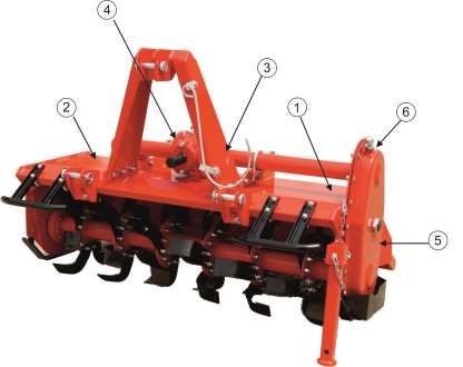
INDEX
 1 Introduction
          1.1) Identifying the machine………………………………………………                 4
          1.2) Technical Specification of Rotary Hoe …………………………….        5
 2 How to work Safety and prevent accidents…………………………...…….              6
   1) Recognize Safety Information…………………………………………………                    6
          2.2) Understand Signal……………………………………………………                     6
          2.3) Follow GENERAL Safety Instructions……………………………...          7
          2.4) Follow EQUIPMENT Safety Instructions…………………………..          8
          2.5) Follow OPERATING Safety Instructions…………………………...         9
          2.6) Follow TRANSPORTING Safety Instructions……………………..        10
          2.7) Follow MAINTENANCE Safety Instructions……………………….         11
          2.8) Follow STORAGE Safety Instructions…………………………….           11
          2.4) Safety Labels…………………………………………………………                      12
 3 Rotary Hoe Setup……………………………………………………..................               15
 4 Tractor Rotary Hoe Setup………………..……………………………………..                     16
 5 Attaching and Detaching of Machine to tractor…………………………….            17
          5.1) Lower Linkage positioning…………………………………………...             17
          5.2) Connecting to the tractor………………………………………........         18
          5.3) PTO Shaft Installation……………………………………….............       19
          5.4) Begin work……………………………………………………............               21
                  I) Operating Instructions……………………………………........       22
                 II) Adjustments…………………………………………….............          23
                          - Lower Linkage Point Adjustment……………………….    23
                          - Friction Clutch Adjustment………………………………      23
                          - Skids Adjustment…………………………………………            24
                          - Tail Flap Adjustment………………………………… ….        25
          5.5) Stopping and Disconnection………………………………………...             26
          5.6) Transporting………………………………………………….............             27
          5.7) Parking………………………………………………………..............               27
 6 Maintenance………………………………………………………………………                               28
          6.1) Recommended Lubrication…………………………………………                  28
                 - GEAR BOX LUBRICATION………………………………........             28
                 - SIDE CASE LUBRICATION………………………………........            29
                 - BEARING HOUSE LUBRICATION…………………………….                30
                 - PROPELLER SHAFT……………………………………………                     30
          6.2) Blade Replacement…………………………………………………..                   31
          6.3) Routine Maintenance………………………………………………...                 33
                 - Prior to Operation………………………………………………                 33
                 - First two hours……………………………………………………                  33
                 - Daily Maintenance (minimum of every 8 hours)………………   33
                 - Weekly Maintenance…………………………………………….                 33
                 - After every 250 hours of work…………………………………..         33
          6.4) Propeller Shaft……………………………………………………….                    33
 7 Troubleshooting and Solutions………………………………………………..                    35
 8 Torque Table……………………………………………………………………..                             37
 9 Parts Identification with Code…………………………………………………                    38
10 Warranty……………………………………………………..…………………….                              49

                                                                         3
SECTION – 1 INTRODUCTION

GANESH AGRO EQUIPMENTS welcomes you to the growing family of new product
owners. The Rotary Hoe is a machine which has been designed for preparing the soil in
nurseries, vineyards, orchards and open filed. The machine uses a chain of gear
transmission to transmit power from the tractor PTO to a rotor assembly.

Each rotor flange can hold 4 to 6 blades that act directly on the soil to uniformly break it
up. The working depth is set by means of the lateral skids. This guarantees a uniform
working depth and levelling of the ground.

The standard machine is equipped as follows:

       - Rear hood with lateral skids to regulate the working depth

       - PTO shaft and relative instruction manual

       - Spanner

1.1    Identifying the machine
       There is identifying registration plate fixed on the machine (fig.1).This plate gives
       you the following information.

              - Manufacturers’ name
              - Standard Weight
              - Model
              - Year of Manufacturing
              - Batch Number

                                                                                               4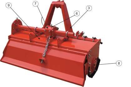
1.2   Technical Specification of Rotary Hoe

      MODEL

                     1020 Mm    902 Mm     15-28   Hp   155 Kg
       XE36   GEAR                                                L/C   24   4
                      40 Inch    36 Inch   11-19   Kw   342 Lbs
                     1195 Mm    1077 Mm    20-30   Hp   170 Kg
       XE42   GEAR                                                L/C   30   5
                      47 Inch    42 Inch   15-22   Kw   375 Lbs
                     1400 Mm    1282 Mm    20-35   Hp   185 Kg
       XE48   GEAR                                                L/C   36   6
                      55 Inch    50 Inch   15-26   Kw   408 Lbs
                     1643 Mm    1523 Mm    25-40   Hp   205 Kg
       XE60   GEAR                                                L/C   42   7
                      65 Inch    60 Inch   19-30   Kw   452 Lbs

                         (A)       (B)

                                           (A)

                                           (B)                                   5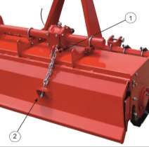
SECTION – 2 HOW TO WORK SAFETY AND PREVENT ACCIDENTS

      Safety is a primary concern in the design and manufacturing of our products.
      Unfortunately, our efforts to provide safe equipment can be wiped out by a single
      careless act of an operator.

      In addition to the design and configuration of equipment, hazard control and
      accident prevention are dependent upon the awareness, concern, prudence and
      proper training of personnel involved in the operation, transport, maintenance
      and storage of equipment.

      It has been said, “The best safety device is an informed, careful operator.” We
      ask you to be that kind of operator.

2.1   Recognize Safety Information

      This is a safety-alert symbol. A careful reading of this manual will allow you to
      understand this new piece of equipment and will provide you all the tools needed
      to use it safely.

      Proper maintenance and knowledge of the safety rules of use will ensure the
      best performance and extend the life of the machine.

      Follow recommended and safe operating practices.

2.2   Understand Signal

      Safety alert symbol is used in conjunction with following Signal words, according
      to the degree of possible injuries that may result operating the implement;

                                            DANGER identifies the most serious
                                            hazards, if not avoided, will result in death
                                            or serious injury.
                                            WARNING indicates a potentially
                                            hazardous situation that, if not avoided,
                                            could result in death or serious injury, and
                                            includes hazards that are exposed when
                                            guards are removed. It may also be used
                                            to alert against unsafe practices.
                                            CAUTION indicates a potentially
                                            hazardous situation that, if not avoided,
                                            may result in minor or moderate injury. It
                                            may also be used to alert against unsafe
                                            practices.
                                            IMPORTANT indicates instruction or
                                            procedure that, if not observed, can cause
                                            damage to equipment or environment.
                                            NOTE indicates helpful information.

                                                                                            6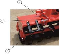
READ – UNDERSTAND – FOLLOW, the safety messages following the Safety
      Alert symbol and Signal Words. Failure to comply with safety messages could
      result in serious bodily injury or death.

2.3   Follow GENERAL Safety Instructions

                           The machine must be used only by authorised and well-trained
                           operators. The operators must have read and understood the
                           instructions of this manual. They must make adequate preparation for
                           the proper use of the machine and in case of doubt about the use of
                           the machine and/or the interpretation of this manual the operator must
                           contact the Manufacturer or the Dealer.

                           The manual must always remain with the machine. In case of loss or
                           damage, request a new copy to the manufacturer or your Dealer.

                           Follow strictly the rules prescribed by the safety pictograms applied to
                           the machine.

                           Be sure that all safety pictograms are legible. If pictograms are worn,
                           they be replaced with others obtained from the Manufacturer and
                           placed in the position indicated by this manual.

                           Before using the machine, make sure that all safety devices are
                           installed and in good working conditions. In case of damages of
                           shields of shields, replace them immediately.

                           Is forbidden to remove or alter safety devices.

                           Before starting and during operation of the implement make sure there
                           are no people or animals in the area of operation: the machine can
                           project material from the back, with risks of serious injury or death.

                           Pay maximum attention to avoid any accidental contact with rotating
                           parts of the machine.

                           During operation, adjustment, maintenance, repairing or transportation
                           of the machine, the operator must always use appropriate Personal
                           Protective Equipment (PPE)

                           Do not operate the implement while wearing loose-fitting clothing that
                           can give rise to entanglement in parts of the machine.

                           Do not operate the implement when tired, not in good condition or
                           under the influence of alcohol or drugs.

                                                                                                      7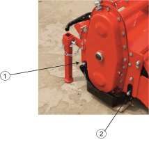
If the use of the machine is required at night or in conditions of
                         reduced visibility, use the lighting system of the tractor and possibly an
                         auxiliary lighting system.

2.4   Follow EQUIPMENT Safety Instructions
                         Use the implement for its intended purpose only. Improper use can
                         damage the implement and cause serious injury to persons, animals,
                         or death.

                         The machine should be used by a single operator driving the tractor.

                         Any unauthorised modification of the machine may cause problems in
                         safety and relieves the manufacturer from any liability for damages or
                         injuries that may result in operators, third parties, and objects.

                         Before using the machine, familiarise yourself with its controls and its
                         working capacity.

                         Do not leave the implement unattended with tractor engine running.

                         Do not operate implement on unstable (muddy or sandy) or rocky
                         ground.

                         Keep the machine clean from debris and foreign objects which may
                         damage functioning or cause injury.

                         Do not use the machine if the category of the connecting pins of the
                         Rotary Hoe does not match that of the tractor hitch system.

                         Do not use the machine with missing bolts, screws, pins or safety pins.

                         Never use the machine to transport or lift people, animals or objects.

                         Make certain that at least 20 % of the total weight (tractor, implement
                         and ballast) is on the front axle of the tractor to ensure stability. Add
                         front ballast if required.

                         Before engaging the tractor PTO, make sure the tractor PTO speed is
                         set as required for this implement (540 RPM). Do not over speed PTO
                         or machine breakage may result.

                         Do not operate the implement if the driveshaft is damaged. The
                         driveshaft could break during operation, causing serious injury or
                         death. Remove the driveshaft and repair or replace it before continuing
                         operation.

                                                                                                     8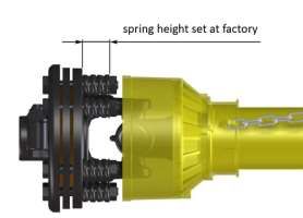
2.5   Follow OPERATING Safety Instructions

                         Before using the machine, be sure to have cleared the operating area
                         from obstacles (stones, branches, debris, etc). Mark all the obstacles
                         that cannot be removed (e.g., by means flags).

                         Never engage the tractor PTO in the presence of people close to the
                         driveshaft. The body, hair or clothing of a person can get caught in
                         rotating parts, causing serious injury or death.

                         Before engaging the PTO and during all operations, make sure that no
                         person or animal is in the immediate area of action of the machine.
                         Never use the Rotary Hoe if people are in his working area.

                         Its forbidden to stand near an implement like this when parts are
                         moving.

                         The operator must operate implement (lifting/lowering) only from the
                         driving seat of the tractor. Do not perform lifting manoeuvres on the
                         side or behind the tractor.

                         Before making changes in direction, turns or going in reverse, slightly
                         lift the implement off the ground after disengaging the power take-off,
                         to avoid damage to the machine.

                         In the presence of step or slopes (greater than 15 degree) the action of
                         this machine may cause instability of the tractor with a risk of tipping
                         off which a consequence may be serious injury or death hazard.
                         Consult the manual for the tractor to determine the maximum slope
                         that the tractor can handle.

                         Always disengage the PTO before raising the implement and never
                         engage the PTO with the implement raised. The machine might throw
                         objects at high speed, causing serious injury or death.

                         Never leave the driver’s seat when the tractor is turned on. Before
                         leaving the tractor, lower the Rotary Hoe to the ground, disengage the
                         PTO, insert the parking brake, stop the engine and remove the key
                         from the control panel.

                         The PTO shield of the tractor and implement side, the driveshaft
                         shielding and the driveshaft retaining chains must be properly installed
                         and in good condition, to avoid the risk of entanglement with serious
                         injury or death.

                         Before engaging the PTO of the tractor, always make sure that the
                         drive shaft is mounted in the correct direction, and that its clamping
                         elements are properly connected both to tractors side and to Rotary

                                                                                                   9
hoe side.
Stop operating immediately if blades strike a foreign object. Repair all
damage and make certain rotor and blades are in good condition
before resuming operation.
Always disengage the tractor PTO when the driveshaft exceed an
angle of 10 degrees up or down while operating. An excessive angle
with driveshaft rotating can break the driveshaft and cause flying
projectiles.
Avoid clutch’s overheating caused by too long or frequent slipping of
the clutch, since it can damage the clutch components. Before
checking slip clutch, make sure it has cooled. Clutch could be
extremely hot and cause a severe burn.
Prolonged use of the implement can cause overheating of the
gearbox. Do not touch the gearbox during use and immediately after, it
could be extremely hot and cause a severe burn.
All repairs to the implement must be performed by qualified and
trained operators, with the tractor engine OFF; the PTO disengaged,
the implement lowered to the ground or on secured stands, the ignition
key OFF and the parking brake set.
2.6 Follow TRANSPORTING Safety Instructions
Before transporting, determine the stopping characteristics of the
tractor and implement.
Transport only at speeds where you can maintain control of the
equipment.
When driving on roads, the implement must be in transport position
adequately raised from the road surface, with tractor lifting hydraulics
locked so that the Rotary hoe cannot be lowered accidentally.
The implement may be wider than the tractor. Pay attention to
transporting for people, animals, buildings/sheds and/or other
obstacles.
When turning, use extreme care and reduce tractor speed.
Do not operate the tractor with weak or faulty brakes or worn tires.
Always use tractor lighting system and auxiliary lighting system for an
adequate warning to operators of other vehicles, especially when
transporting at night or in conditions of reduced visibility.
10In the case of lifting this implement, make sure that any lifting device is
suitable to operate safely, and use only the lifting points prescribed on
Rotary Hoe.
2.7 Follow MAINTENANCE Safety Instructions
All maintenance and repair operations must be performed by qualified
and trained operators, with the tractor engine off; the PTO disengaged,
the Rotary Hoe lowered to the ground or on security stands, the
ignition key off and the parking brake set.
Perform repairs and replacements part should only be original spare
parts provided by the manufacturer, importer or your dealer.
Perform maintenance operations using appropriate Personal
Protective Equipment (protective eyeglasses, har hat, hearing
protection, safety shoes, overall and work gloves, filter mask).
Before any maintenance operation, make sure that the parts which
become hot during use (friction clutch, gearbox etc.) have cooled.
Do not perform repairs that you do not know. Always follow the manual
instructions and in case of doubt contact the Manufacturer or your
dealer.
Do not swallow fuels or lubricants. In case of accidental contact with
eyes, rinse well with water and consult a doctor.
2.8 Follow STORAGE Safety Instructions
Never leave the tractor unattended with the implement in the lifted
position. Accidental operation of lifting lever or a hydraulic failure may
cause a sudden drop in the unit which result in injury or death.
Following the operation, or before unhooking the implement, stop the
tractor, set the brakes, disengage the PTO, lower the attached
implement to the ground, shut off the engine, remove the ignition key
and wait for all moving parts to stop.
Make sure all parked machines are on a hard, level surface and
engage all safety devices.
Place support blocks under implement as needed to prevent the unit
from tipping over onto a child and/or an adult. An implement that tips
over can result in injury or death.
11Store the unit in an area away from human activity.
2.9 Safety Labels
The following safety labels are posted on the machine. Read them carefully and memorize their
meanings. Always replace them if they are det ached or damaged taking care of putting them as
indicated fig.7
12Disengage the PTO, turn OFF the tractor engine,
remove the key and ensure that all rotating parts
have stopped before approaching the implement.
Read the operator’s manual before performing any
1
maintenance operation. Thrown or flying objects
hazard.
Safety Equipment
2
Crushing hazards & Thrown or Flying objects
3
hazards.
4 Operate only with 540 rpm PTO
5 Rotating Gears
6 Oil filling point
7 Lifting point
138 Grease filling point
9 Hand Hazard
14SECTION – 3 ROTARY HOE SET UP
Preparing the machine for work must be done with the PTO disengaged the
machine on the ground and tractor OFF and blocked.
Before starting the machine, the SETUP includes following inspection at machine
level:
- Check the Rotary hoe is suited to the tractor horsepower.
- Check oil and grease lubrication point as per Manufacturer’s
requirement for relevant machine.
- Guards are properly installed and all parts subject to wear and tear
are in good working condition.
- Safety decals are on the machine and clean.
- Bolts and nuts are tightened.
15SECTION – 4 TRACTOR SETUP
4.1 Use your Tractor Operator’s Manual
Always refer to your Tractor Operator’s Manual for specific detailed
information regarding operation of your tractor.
Following tractor related information uses tractors to illustrate
preparation, attachment and operational procedures.
Use your tractor OM for detailed information, as procedures will
vary by equipment.
4.2 Tractor Stability and Lifting Capacity Check
When machine is jointed to tractor, It becomes an integral part of it. Attached
equipment’s weight is closely related with road position and stability of tractor. In
normal conditions, it is assumed that 20% of tractor weight is carried by front axle.
In this case, attached equipment’s weight should not be greater than 30% of
tractor weight. This factor can be summarized in following formulas:
When machine is attached to tractor, front weights should put through above
mentioned formula. These weights should be calculated according to capacity of
tractor’s lifting weight and packing.
16SECTION – 5 ATTACHING AND DETACHING TO THE TRACTOR
The implement is delivered fully assembled and equipped with a driveshaft with
friction clutch (clutch discs) and related operating manual.
When the machine is delivered, check that there is no damage to the implement
and driveshaft. In case of damage or missing parts immediately notify the
manufacturer, importer or your dealer.
5.1 Lower Linkage Positioning
The XEOS-Series Rotary Hoes are designed to be mounted on tractors equipped
with :
3-point Hitch Category I (ISO 730 standard);
Quick Hitch Category I (ASABE Standard).
The position of the lower hitches must be adjusted accordingly.
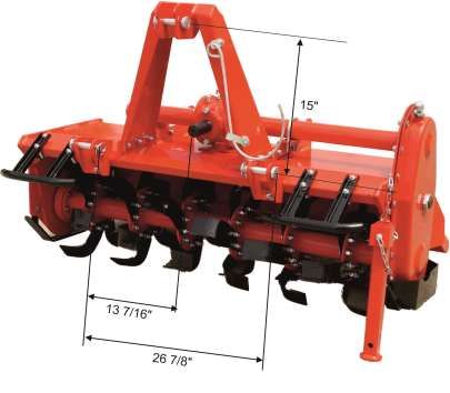
If the tractor is equipped with a Quick Hitch Category I (ASABE Standard), verify
that the lower linkage point shows the pins oriented up (see figure), so that the
distance between upper and the lower pins is 15” (381 mm), as required from the
standard.
If this does not occur, proceed as follows for each of the two linkage points:
17 Remove the U-Bolt and the linkage point from the square tube;
Invert the linkage point orientation and reposition it on the square tube at
distance of 13 7/16” from the centre of Rotary Hoe PTO. At the end of the
operation the lower linkage point should be positioned symmetrically to
Rotary Hoe PTO, at distance of 26 7/8” (683 mm);
Re-tighten the U-bolt, referring to the tightening table of this manual.
If the tractor is equipped with a 3 -point Hitch Category I (ISO 730 standard),
verify that the lower linkage point shows the pins oriented down (opposite than
figure above), so that the distance between upper and the lower pins is 18” (460
mm approx.), as required from the standard.
If this not occurs, proceed as follows for each of the two linkage points:
Remove the U-bolt and the linkage point from the square tube;
Invert the linkage point orientation and reposition it on the square tube at
distance of 13 7/16” from the centre of Rotary Hoe PTO. At the end of the
operation the lower linkage points should be positioned symmetrically to
the Rotary Hoe PTO, at distance of 26 7/8” (863 mm)
Re-tighten the U-Bolt, referring to the tightening table of this manual.
Remove from upper position and fit the lower pins bushings provided for
coupling with Quick Hitch, through the extraction of the pins. Replace the
pins when finished. Store the bushings for possible future use.
5.2 Connecting to the Tractor
Implement can be attached to the suitable category tractor. Follow below
procedure for attaching the implement to the tractor.
Disengage PTO Drive
Trained person is required to attach and detach
from the tractor. Else may cause major injury to
operator and severe damage to implement and
tractor.
Implement should always be park on level ground
for attaching and detaching to tractor safely and
easily.
Before attaching implement to the tractor, check
for any accessories fitted on tractor like drawbar,
swinging drawbar, automatic hitch etc. for any
hindrance, restriction, proper functioning and free
up and movement of equipment. If required
remove accessories before attaching equipment.
183
1 2
When using tractors with multi-speed PTO, be certain that PTO is set for
prescribed RPM.
1. Bring the tractor back and insert LH lower link (1) of the tractor to the
corresponding hitch pin of the equipment and lock it with the help of latch
pin (Fig.1)
2. Similarly attach RH lower link (2) of the tractor to the corresponding hitch
pin of the equipment. If required adjust height of lower link with the help of
adjustable lift rod.
3. Attach top link (3) of tractor to top hitch point of the equipment. Adjust
length of top link if required to reach and align to the required hole on the
top hitch point.
5.3 PTO Shaft Installation
The universal propeller shaft supplied, with the machine,
IMPORTANT is of standard length. Therefore it might be necessary to
adapt the universal drive shaft
The propeller shaft must have protective covers.
The propeller shaft without covers should never be
used.
IMPORTANT The tractor may not be running during the
mounting and dismounting of the shaft.
No other persons should be around the propeller
shaft during processes with the shaft.
Make sure the PTO shaft length is compatible with the different working positions
of the implement. If the PTO shaft is too long it might bend and damage may
occur to the tractor or implement.
19Place the tractor and the implement on a flat surface. Attach the 3 point linkage
of the tractor (see the section – 5.2 connecting to the tractors)
Distance
Find the length between the grove of PTO output on the tractor, and the PTO
input on the implement when the implement and tractor is in horizontal position.
Before operating the implement ensure that the size of the propeller shaft is
adequate. The PTO shaft supplied with the machine comes in a standard length.
Therefore it may need to be shortened depending on your tractor and implement.
When the propeller shaft is at its minimum length, there must be at least a 4 cm
of distance between the ends of each transmission tube and the yoke side.
When the propeller shaft is at maximum operational extension, there must be an
overlap between the tubes profiles of 15 cm at least.
Before operating the implement the first time,
make sure that the propeller shaft is lubricated in
IMPORTANT
accordance with how indicated in the instruction
booklet.
20 Before operating the implement the first time, and
after long periods of inactivity, make sure that the
propeller shaft clutch has not seized. It may be
necessary to ‘slip’ the clutch and reset due to
possible oxidation of the components that may
compromise the correct slipping during the usage.
Always engage the tractor PTO at low rpm to
minimise the effect of the peak torque on the
propeller shaft and the machine.
5.4 Begin work
Before the start-up and before each use, perform the following pre-operation
inspections and service of the implement;
Check that the implement has no damaged functional parts and has all
mechanical parts are good condition. Repair and / or replace the damage
parts;
Check that the implement has no missing parts (pins, safety pins, plug oil
so on). Restore the missing parts;
Check that all guards and safety devices have no damages and are
properly positioned. Repair and / or replace the damaged shields, restore
the correct position;
Verify that the PTO driveshaft is properly installed (see section :
connecting to the tractor);
Check that the propeller shaft clutch is in good condition, and that its
components are not subject to “sticking” (see section: Maintenance –
Propeller shaft);
Check the presence of lubricant in all greasing points of the implement
(propeller shaft, supports so on) (see section : Maintenance / Propeller
shaft and Maintenance / Support rotor);
Check for oil leaks from the gearbox or the transmission side cover.
Identify the reason of loss then repair and / or replace the damaged
components;
Check the correct oil level in the gearbox and in transmission side box
(see section : Maintenance)
Check that blades are not excessively worn and the relating hardware is
correctly tightened (see section : Maintenance)
Check that all hardware (nuts, bolts etc.) are properly tightened. Refer to
the tightening table in the manual for proper torque value;
Check that all safety labels are correctly positioned, in good condition and
legible. Replace any damaged labels;
Check that there is no constraint that may prevent the movement of
equipment. Remove any constraints.
Before the start-up and before each use, make the following checks on the
operating area you intend to operate;
21 Check that area is clear of foreign objects (rocks, branches or debris).
Remove any obstacle and visibility highlight obstacles that cannot be
removed (e.g., with flags);
Make sure that in the area you intend operate there are no people or
animals;
Make sure the soil to be worked is not too grassy, muddy, sandy or rocky.
Before conducting the above inspections and service,
make sure the tractor engine is OFF, all rotation parts
are completely stopped, and the tractor is in park with
the parking brake engaged. Make sure the implement
is resting on the ground or securely blocked up and
the tractor lifting hydraulics locked.
Once all the checks above have been done, start the tractor and the implement
as follows:
Start the tractor and engage the tractor PTO at low rpm, making sure that
the implement is NOT in the raised position but close to the ground, then
increase speed engine until to 540 rpm;
Lower the implement on the ground and simultaneously start driving the
tractor forward at low speed. Subsequently, increase the ground speed
depending on ground conditions;
If the outside temperature is very cold, its recommended to engage the
PTO and have the implement operate at low speed (with the tractor
stationary) to warm oil and lubricate parts;
Drive for a while operating the implement then stop the tractor to check
the quality of the work performed. If you need to get off the tractor, lift the
implement just out of the ground, reduce engine speed and disengage
PTO, stop engine and remove the ignition key;
If the working depth and / or soil texture are not as desired, correct by adjusting
the skids and/or the rear cover (see section: Adjustments)
I) Operating Instructions
During operations: OPERATE ACCORDING TO FOLLOWING
INSTRUCTIONS
Always keep the tractor engine at a speed that delivers 540 rpm to the
implement. Failure to do so will affect the performance of the
implement;
Always keep a tractor speed suitable to conditions of the soil (from 2 to
10 km/h approx.) Reduce speed in the case of hard or stony soils;
Choose a driving pattern that provides the maximum pass length and
minimizes turning;
When working in the hills, always work up and down the hill. Never
work cross the hill;
When changing directions or reversing, disengage the PTO and
slightly lift the implement from the ground to avoid damage to the
machine;
22 Periodically check for foreign objects wrapped around the rotor shaft
and remove them, after disengaging PTO, turning off tractor engine,
and removing ignition key;
If the blades strike foreign object, or in case of excessive friction clutch
slippage, stop operating immediately, idle the engine speed and
disengage the PTO. Wait for all rotating parts to come to a stop, then
raise the implement and proceed to inspect damage, after stopped the
tractor, set the parking brake, stopped engine and removed the ignition
key. Repair any damage immediately, and make sure rotor and blades
are in good condition before restarting operation;
Avoid friction clutch overheating. This is caused by operating in heavy
conditions or incorrectly adjusted clutch. If your clutch overheats, it can
damage clutch components which will them not operate correctly which
may then result in damage to your implement.
Typical problems that may occur operating the implement are described
in the Troubleshooting section, together with their solutions.
II) Adjustments
All adjustment operations must be performed
with the tractor engine OFF, the PTO
disengaged, the implement lowered to the
ground or on security stands, the parking
brake set and the ignition key off.
- Lower Linkage Point Adjustment
It is possible to adjust the lower linkage point position loosening
the bolts 1 (see picture) and sliding the linkage point 2. Tighten
the bolts after making any adjustment required.
- Friction Clutch Adjustment
The PTO shaft and friction clutch are designed to transmit adequate
power to the implement.
The clutch preserves the machine from overloads, through the
slipping of friction discs, and limits the max torque transmissible to
a calibrated value set at the factory. It is recommended, therefore,
23to set the clutch and regularly adjust to avoid damages to the
machine or the propeller shaft.
Friction clutches are designed to be adjusted. If slipping is too
frequent, it means that the calibration is too low and the clutch
needs to be adjusted (tightened).
In this case, the tightening of the nuts will compress the springs
which will increase the drive to the implement.
On the contrary, a loosening of the nuts will decrease the drive to
the implement.
For details about clutch adjustment, refere to
the user manual of the manufacturer of the
propeller shaft installed.
IMPORTANT
The manufacturer is not liable for damages
resulting from a wrong modification of the
clutch calibration.
Excessive tightening of the springs can
prevent the clutch from slipping and then
there is no protection for the machine from
overload.
NOTE
Make sure that the height of all the
compressed springs is equal to prevent the
clutch malfunctioning.
- Skids Adjustment
The working depth of the implement is determined by the position of the
side skids. It may be increase by raising the skids and decreased by
lowering them. Its important that both skids are adjusted to the same
height.
To adjust the working depth, perform the following steps;
24 Lift the machine, put it safely on security stands, then switch the
tractor engine off, disengage PTO, set the parking brake and off the
ignition key;
Loosen the bolt in the front of the skid (bolt 1 – see picture);
Unscrew and remove the bolt on the rear of the skid (bolt 2 – see
picture);
Adjust the height of the skid through the holes, as desired;
Reinstall the bolt 2 (refer to the tightening table of this manual for
proper torque values);
Tighten the bolt 1 (refer to the tightening table of this manual for
proper torque value);
When finished, verify that both skids are at same level, and check
if the front of the implement is levelled to the back, when lowered
to the ground. Adjust with the 3-point top link if necessary.
- Tail Flap Adjustment
The XEOS – Series Rotary Hoes are equipped with a tail flap with a
chain.
The position of the tail flap is adjustable by varying the number of chain
links included between distances ½, which should remain tensioned
under the weight of the flap. (i.e. links between the rear flap U-bolt 1 and
the slot of the frame 2 ).
25 To raise the tail flap, reduce the number of chain links in tension.
This operation, together with the increase of the tractor ground
speed, allows to have a coarser soil texture;
To lower the tail flap, increase the number of chain links in tension.
This operation, together with the reduction of the ground speed will
result in finer soil texture.
To avoid the risk of crushing or
cutting off fingers, raise or lower the
tail flap only from the lower edge, not
from the sides.
5.5 Stopping and Disconnection
To stop the implement at the end of a working session:
Bring the tractor to a complete stop;
Place the transmission in park or neutral;
Reduce the engine speed, then disengage the PTO;
Wait for stopping of all rotating parts;
Lower the implement to the ground;
Set the parking brake;
Shut down the engine and remove the key before existing the tractor;
Do the cleaning and maintenance required to make the machine ready for
later use (see Section – Maintenance)
Never leave the tractor unattended with
the implement in the lifted position
To disconnect the implement from the tractor (e.g. to make a change of
implement)
Adjust the skids to their lowest position (see section – adjustments);
Adjust the support stand to the lowest position, through the use of relative
retaining pin;
Park the tractor on a dry and level surface;
Reduce the engine speed, then disengage PTO;
Wait for stopping of all rotating parts with implement lowered to the ground;
Set the parking brake;
Shut down the engine and remove the key before exiting the tractor;
Place safety blocks under implement to prevent the unit from tipping over
onto a child and /or an adult. An implement that tips over can result in
injury or death;
Disconnect the driveline from the tractor PTO and rest if on the provided
support of the implement;
Disconnect the top link and rear lifting arms of the tractor from the
implement hitches;
Check the implement stability. If needed, place additional safety block;
26 Get on the tractor, start the engine and move away from the implement
slowly;
Make sure the implement remains stored in a protected area; to prevent
those unauthorised personnel can approach it.
If you do not intend to use your implement for a long period of time, (e.g., at the
end of the season), do cleaning and maintenance operations as specified in
Section – MAINTENANCE and STORAGE
5.6 Transporting
To set the implement for transportation, perform the following steps:
Idle tractor engine, disengage tractor PTO, and wait for stopping of all
rotating parts;
Lift the implement far enough off the ground to clear any objects BUT not
to a point where the PTO Shaft comes in contact with the tractor or
implement. A minimum gap of 2 cm should be left between the tubes and
tractor and Rotary Hoe (see also Section – PTO Shaft Installation)
Lock the tractor lifting hydraulics, turn off the engine, set the parking brake,
remove ignition key and get off the tractor;
Adjust the support stand to the highest position, through the use of the
retaining pin, to prevent its possible damage during transport.
When driving on public roads operators must strictly follow local laws and traffic
regulations.
When driving on public road, reduce your speed, be
aware of traffic around you and proceed in such a
way that faster moving vehicles may pass you
safely.
5.7 Parking
The following steps should be done when preparing to store the implement or
unhitch it from the tractor.
Wash and dry the machine
Put the PTO shaft on the proper place
Check all the moving wear parts; for damage and excessive wear, contact
your dealer or qualified service technician for repair.
Check bolts and nuts for proper tightness
Check oil levels
Protect and lubricate the non-painted parts.
Make sure that the Rotary Hoe is placed on a suitable flat hard standing.
27SECTION – 6 MAINTENANCE
Proper and regular maintenance ensures a long life of the implement avoids
failures and saves time and repair costs.
Periodic inspections and maintenance operations described in this section must
be performed by the operator in the times and terms prescribed. Failure to
comply with maintenance prescriptions can compromise the functioning and
duration of the machine, and consequently invalidate the warranty.
The frequency of maintenance indicated refers to normal conditions of use: it
must be intensified in severe operating conditions (frequent stops and starts,
prolonged winter season, etc)
Repairs, maintenance, and modifications other than those mentioned in this
paragraph should NOT be performed without consulting the manufacturer or your
dealer. Manufacturer, as the case, may give the authorisation to proceed with the
repair together with all necessary instructions.
Wrong or inappropriate repairs or maintenance may generate abnormal
operating conditions, equipment damage and generate risks for the operator.
For safety reasons, all maintenance operations must
be performed with tractor PTO disengaged,
implement stopped and completely lowered to the
ground or onto support blocks, parking brake set,
tractor engine shut off, and ignition key removed.
Respect the environment. Store or dispose of
IMPORTANT unused chemicals as specified by the chemical
manufacturer.
6.1) Recommended Lubrication
The various maintenance instructions are listed below. Doing these maintenance
jobs at regular intervals will not only lengthen the machine life but also reduce its
maintenance costs substantially.
GEAR BOX LUBRICATION
Lubricant : SAE EP 80W90 Gear Oil
Check the oil level every 50 hours, making sure the oil mark left on the dipstick of
the filling plug (top of the gearbox) is located between the two reference marks
(minimum and maximum).
28Filling Plug
1.5 LTr
If the oil is below the minimum, fill up to restore the correct level and oil change
must be performed:
After the first 50 working hours;
Each 500 working hours;
To carry out an oil change;
Place a tank under the oil drain plug (bottom of the gearbox);
Unscrew the oil drain plug and drain the oil completely into the tank;
Retighten the drain plug;
Unscrew the oil filling plug;
Fill with oil to achieve the correct level (between the two reference dipstick
marks);
Retighten the filling plug;
Dispose the discharged oil into containers for used oil.
SIDE CASE LUBRICATION
Lubricant : SAE EP 80W90 Gear Oil
Filling Plug
Level Plug
Check the oil level every 50 hours. Make sure it reaches the level plug on the
transmission cover.
29The oil change must be performed every 500 working hours.
To make the oil change:
Remove the skid from the transmission side;
Place a tank under the oil level plug;
Unscrew the oil level plug and drain the oil completely into the tank;
Retighten the level plug;
Unscrew the oil filling plug (top of transmission cover);
Fill up to the correct level (until level plug);
Retighten the filling plug;
Replace the side skid;
Dispose the discharged oil into containers for used oil.
BERAING HOUSE LUBRICATION
Lubricant: SAE multi-purpose lithium-type grease.
Grease the rotor hub support every eight (8) working, through a suitable grease
gun.
Grease
Nipple
Make sure you clean the grease nipple before using
a grease gun.
IMPORTANT
Do not let excess grease collect on or around these
parts especially when operating in sandy areas.
PROPELLER SHAFT MAINTENANCE
Lubricant: SAE Multi-purpose lithium-type grease
Grease crosses, sliding parts of protective shielding and driveshaft transmission
tubes.
30For details about maintenance and lubrication of the
IMPORTANT propeller shaft, refer to the user manual of the
propeller shaft manufacturer.
Propeller Shaft Clutch:
Exposure of the implement and propeller shaft to environmental elements,
as well as a long period of inactivity, generally results in oxidation (rust) of
some clutch components. This can result in a seized clutch which will offer
no protection to the implement.
To avoid a seized clutch, the operator must perform a short “run-in” of the
clutch, as follows:
Take not of the height of the compressed springs;
Loosen the nuts of the compress the springs;
Connect the implement to the tractor (see section : connecting to
the tractor);
Connect the propeller shaft (see section : Propeller shaft
installation);
Start the tractor and engage PTO for few seconds. You should hear
and/or see the clutch slip. If not, turn off the tractor, remove the key
and wait for all components are stopped before dismounting from
the tractor and loosen a little more;
Turn off the tractor, remove the key and wait for all components are
stopped before dismounting from the tractor;
Tighten the nuts (gradually) to compress springs and re-establish
torque (drive) to the implement as per instruction on page.
6.2 Blade Replacement
Frequently check the wear condition of blades through visual inspection.
The wear of blades is very variable depending on the type of soil.
Replacement of the blades is necessary when the operator notices
increase of power absorption during operation or when the blade
dimension is significantly reduced compared to the original.
The use of the machine with blades in bad condition compromises the
quality of work.
31Before performing replacement of the blades:
Idle tractor engine, set the parking brake, disengage tractor PTO,
and wait for all moving parts to come to a complete stop;
Slightly raise the implement from the ground or place on safety
blocks or mechanical stands;
Lock the height control level of tractor’s hydraulics;
Turn off the tractor and remove the key.
To perform the replacement of blades:
Remove the two bolts and washers clamping the blade to the rotor
flange, then remove the blade;
Position the new blade exactly where the worn blade was, then
tighten the bolts, referring to the tightening table of this manual for
proper torque values. Be sure to install the blade with cutting edge
in front of the direction of rotation;
Repeat the same procedure for all the other blades.
At the end of the replacement, make sure the blades have the right helical
arrangement, as shown in the figure:
Periodically check the tightness of screws and nuts, and tighten if
necessary.
Remove and install one blade at a time to ensure
IMPORTANT blades are correctly oriented when installed.
Replace worn blades only with original parts.
Remove and install one blade at a time to
ensure blades are correctly oriented when
installed. Replace worn blades only with origina l
parts.
326.3 Routine Maintenance
Before oiling, maintaining or adjusting the
implement, switch off the tractor engine.
The following routine maintenance procedures are recommended, to
ensure the efficient and safe operation of your Rotary Hoe, as well as
maximizing the work life of the machine.
- Prior to Operation
1. Ensure that gearbox is adequately lubricated
- First two hours
1. Check that all bolts are tightened correctly
2. Check oil level of gear box. Top up if necessary.
- Daily Maintenance (minimum of every 8 hours)
1. Separate and lubricate the drive shaft.
2. Grease universal joints.
3. Check the level of oil in the gearbox, and top up if necessary.
4. Check the underside of the Rotary hoe, in particular the blades.
Replace blades if there are visible signs of damage or excessive
wear.
5. Ensure bolts are tightened securely on the blades and skids.
6. Ensure cuttings have not built up around the gearbox or cutter
unit.
- Weekly Maintenance
1. Perform all steps as per daily service.
2. Check & tightened all nuts and bolts on the rotary hoe.
3. Clean away any residue on the rotary hoe.
4. After approximately every 50 hours of work, check universal
joints for excessive wear.
- After every 250 hours of work
1. Inspect thoroughly the universal joints, and replace any worn
parts.
2. Complete full service, as per daily and weekly procedures.
6.4 Propeller Shaft
Disconnect the propeller shaft from the tractor and slide apart.
Clean and coat the inner tube of the propeller shaft with a light film of
grease on daily basis or every 8 hours and then reassemble.
3334
SECTION – 7 TROUBLE SHOOTING

         PROBLEM                           CAUSE                         SOLUTIONS
Gearbox/transmission case      Low oil level.                  Add oil to the
noise noticeable and                                           gearbox/transmission case.
constant                       Worn gears.                     Replace gears
Intermittent                   Loose blades.                   Tighten blades hardware
noise from implement
                               Gear tooth damaged.             Replace damaged gear
Noise and/or vibration         Blades worn or damaged.         Replace blades.
from the implement
                               Bearings damaged.               Replace bearings.

                               The front of the implement is   Adjust 3-point top link of
                               not levelled to the back.       tractor making implement
                                                               PTO parallel to the ground.
                               Rotor damaged.                  Repair/replace rotor

                               Hard soil.                      Reduce ground speed
Driveline vibration            Worn driveshaft.                Replace driveshaft.

                               Machine lifted too high.        Lower machine and readjust
                                                               tractor lift stop.
                               Debris wrapped on the rotor.    Remove debris.
Rotor stops turning            Slip clutch is slipping.        Reduce load to implement or
                                                               Adjust slip clutch.
                               Broken chain in chain box.      Repair broken link.
Machine skip or leaves         Badly worn blades.              Replace worn blades.
crop residue
                               Slip clutch is slipping.        Adjust slip clutch or
                                                               reduce load.
                               Ground speed too fast for       Reduce ground speed.
                               Conditions.
Smoke and/or hot smell         Debris wrapped around in        Remove debris.
from the implement             blades and/or rotor.

                               Low oil level in the gearbox.   Add oil

                               Slip clutch is slipping.        Reduce load to machine or
                                                               adjust slip clutch.
Gearbox overheating            Low oil level.                  Add oil.

                               Hard soil.                      Reduce ground speed.
Blades wear frequently         Muddy or sandy soil.            Reduce ground speed.
Blades break frequently        Stony soil.                     Reduce ground speed.
Oil leaking from gearbox/      Gearbox/transmission case       Drain to the proper level.
transmission case              Overfilled.

                               Loose filling/drain plug.       Tighten filling/drain plug.

                               Damaged breather plug.          Replace breather plug.

                                                                                             35
Damaged seals. Replace seals.
Implement depth The implement is carried by a Lower tractor 3-point arms.
Insufficient tractor.
Tractor has insufficient power. Increase PTO speed
Skids need adjusting. Adjust skids.
Blades worn or bent. Replace blades.
Blades incorrectly installed. Install tines correctly.
Debris entangled in blades Clear rotor and/or blades
And/or rotor.
Soil texture too coarse Tail flap too high. Lower tail flap.
PTO speed too slowly. Increase PTO speed.
Ground speed too fast. Reduce ground speed.
Soil texture too fine Tail flap too low. Raise tail flap
Ground speed too slow. Increase ground speed.
Implement choking up Blades worn or bent. Replace blades.
with soil
Blades incorrectly installed. Install tines correctly.
Tail flap too low. Raise tail flap.
Soil too wet. Wait until the soil dries.
Implement ‘skipping’ on Blades incorrectly installed Install blades correctly
the ground or leaving crop (wrong helical arrangement, (replace right helical
residue cutting edge in the wrong arrangement, position cutting
Direction...) edge in front of rotation
direction...)
Debris entangled in blades Clear rotor and/or blades.
And/or rotor.
Ground speed too fast. Reduce ground speed.
Soil too hard. Reduce ground speed and
make tilling in more steps.
Soil not uniform Blades worn or damaged. Replace blades.
Skids not aligned.
Left side not levelled with the Align skids.
right side.
Adjust tractor 3-point arms.
Tractor struggling (under Excessive working depth. Lower skids.
too much load)
Excessive PTO speed. Reduce PTO speed.
36SECTION – 8 TORQUE TABLE
Check frequently Rotary Hoe hardware to make sure that screws and bolts are
tightened according to torque values listed in the following table:
37SECTION – 9 PARTS IDENTIFICATION WITH CODE
38STUB AXLE DRIVE PLATE ASSEMBLY (XEOS SERIES)
39Item Part Number Qty Part Name
1 12010001 6 Hex Bolt M10 x 1.5 x 30
2 12010002 6 Spring Washer 10 M
3 12010003 1 Stub Axle Cover
4 12010004 1 Stub Axle Drive Plate
5 12010005 1 Circlip 95 MM
6 12010006 1 Bearing 6308
7 12010007 1 Oil Seal 50 x 75 x10
8 12010008 1 Stub Axle Housing
9 12010009 1 Stub Axle Shaft
10 12010010 1 Dust Cover
11 12010011 6 Plain Washer 10 MM
12 12010012 6 Hex Bolt M10 x 1.5 x30
13 12010013 1 Gasket
14 12010014 1 Oil Nipple
40SIDE DRIVE TRANSMISSION ASSEMBLY (XEOS SERIES)
41Item Part Number Qty Part Name
1 12020001 20 Hex Bolt M10 x 1.5 x 30
2 12020002 20 Plain Washer – 10 mm
3 12020003 1 Side Drive Transmission Cover
4 12020004 1 Air Breather Threaded Plug
5 12020005 1 Air Breather
6 12020006 1 Oil Level Gauge
7 12020007 1 Oil Drain Out Plug
8 12020008 1 Cover Bush
9 12020009 1 Hex Nut M10 x 1.5 x 30
10 12020010 1 Side Drive Transmission Cover Gasket
11 12020011 1 Cotter Pin
12 12020012 1 Castle Nut
13 12020013 1 19 Teeth Spur Gear
14 12020014 1 Bearing 30207
15 12020015 1 29 Teeth Spur Gear
16 12020016 1 Bearing 30207
17 12020017 1 Bearing 6308
18 12020018 1 Circlip 95 MM
19 12020019 1 24 Teeth Spur Gear
20 12020020 1 Castle Nut
21 12020021 1 Cotter Pin
22 12020022 1 Side Drive Transmission Plate
23 12020023 1 O Ring 34 MM
24 12020024 1 Idle Pin
25 12020025 1 RD Axle Housing
26 12020026 1 Oil Seal 50 x 75 x 10
27 12020027 1 R D Axle Shaft
28 12020028 1 Dust Cover
29 12020029 6 Plain Washer 10 MM
30 12020030 6 Hex Bolt M10 x 1.5 x 30
31 12020031 1 RD Axle Housing Gasket
32 12020032 1 Circlip
33 12020033 20 Nylock Nut 10 MM
34 12020034 6 Hex Bolt M10X 1.5 x30
35 12020035 6 Spring Washer 10 MM
42GEAR BOX ASSEMBLY ( XEOS SERIES)
43Item Part Number Qty Part Name
1 12030001 2 Hex Bolt M10 x 1.5 x 25
2 12030002 2 Spring Washer 10 MM
3 12030003 1 Gear Box Front Cover
4 12030004 1 Gear Box Front Cover Gasket
5 12030005 1 Oil Seal 35 x 72 x 10
6 12030006 1 Bearing 30207
7 12030007 1 Input Shaft (XE/XP SERIES)
8 12030008 1 PTO Safety Cover (XE/XP SERIES)
9 12030009 1 13 Teeth Pinion (XE/XP SERIES)
10 12030010 1 Bearing 30209
11 12030011 1 Back Cover Gasket (XE/XP SERIES)
12 12030012 1 Gear Box Back Cover (XE/XP Series)
13 12030013 4 Spring Washer 10 MM
14 12030014 4 Hex Bolt M10 x 1.5 x 25
15 12030015 1 Gear Box Housing (XE/XP Series)
16 12030016 1 Gear Box Gasket (XE/XP Series)
17 12030017 1 Gear Side Support Pipe (XE Series)
18 12030018 8 Spring Washer 10 MM
19 12030019 8 Hex Bolt M10 x 1.5 x 25
20 12030020 2 Side Support Pipe Clamp
21 12030021 4 Hex Bolt M10 x 1.5 x 35
22 12030022 4 Nylock Nut 10 MM
23 12030023 1 Oil Level Plug
24 12030024 1 Air Breather
25 12030025 1 Cotter Pin
26 12030026 1 Castle Nut
27 12030027 1 23 Teeth Crown
28 12030028 1 Bearing 30210
29 12030029 1 Oil Seal 50 x 75 x 10
30 12030030 1 Spacer
31 12030031 1 Jack Shaft Housing Gasket
32 12030032 1 Jack Shaft Housing Pipe (XE36)
33 12030033 1 Jack Shaft Housing Pipe (XE42)
34 12030034 1 Jack Shaft Housing Pipe (XE48)
35 12030035 1 Jack Shaft Housing Pipe (XE60)
36 12030036 4 Hex Bolt M10 x 1.5 x 35
37 12030037 4 Nylock Nut 10 MM
38 12030038 1 Jack Shaft Housing Pipe Gasket
39 12030039 1 Jack Shaft (XE36)
40 12030040 1 Jack Shaft (XE42)
41 12030041 1 Jack Shaft (XE48)
42 12030042 1 Jack Shaft (XE60)
44You can also read