Assembly and Operating Manual - ERS 135 - 210 / 560V Electrical turning unit with torque motor - Schunk
←
→
Page content transcription
If your browser does not render page correctly, please read the page content below
Translation of Original Operating Manual

Assembly and Operating Manual
ERS 135 - 210 / 560V
Electrical turning unit with torque motor
Imprint

                         Imprint
Copyright:
This manual is protected by copyright. The author is SCHUNK GmbH & Co. KG. All rights
reserved.
Technical changes:
We reserve the right to make alterations for the purpose of technical improvement.
Document number: 389064
Version: 04.00 | 18/01/2021 | en

Dear Customer,
thank you for trusting our products and our family-owned company, the leading
technology supplier of robots and production machines.
Our team is always available to answer any questions on this product and other solutions.
Ask us questions and challenge us. We will find a solution!
Best regards,
Your SCHUNK team

Customer Management
Tel. +49-7133-103-2500
Fax +49-7133-103-2239
cms@de.schunk.com

     Please read the operating manual in full and keep it close to the product.

2              04.00 | ERS 135 - 210 / 560V | Assembly and Operating Manual | en | 389064
Table of Contents
Table of Contents
1 General.................................................................................................................... 5
1.1 About this manual ................................................................................................ 5
1.1.1 Presentation of Warning Labels ............................................................... 5
1.1.2 Applicable documents .............................................................................. 6
1.1.3 Sizes .......................................................................................................... 6
1.1.4 Versions .................................................................................................... 6
1.2 Warranty .............................................................................................................. 6
1.3 Scope of delivery .................................................................................................. 6
1.4 Accessories ........................................................................................................... 7
2 Basic safety notes ................................................................................................... 8
2.1 Intended use......................................................................................................... 8
2.2 Not intended use .................................................................................................. 8
2.3 Constructional changes ........................................................................................ 8
2.4 Spare parts ........................................................................................................... 8
2.5 Ambient conditions and operating conditions ..................................................... 9
2.5.1 Electromagnetic compatibility.................................................................. 9
2.6 Personnel qualification......................................................................................... 9
2.7 Personal protective equipment.......................................................................... 10
2.8 Notes on safe operation ..................................................................................... 10
2.9 Transport ............................................................................................................ 11
2.10 Malfunctions....................................................................................................... 11
2.11 Disposal .............................................................................................................. 11
2.12 Fundamental dangers......................................................................................... 11
2.12.1 Protection during handling and assembly .............................................. 12
2.12.2 Protection during commissioning and operation ................................... 12
2.12.3 Protection against dangerous movements............................................. 13
2.12.4 Protection against electric shock............................................................ 14
2.13 Notes on particular risks..................................................................................... 15
3 Technical data......................................................................................................... 17
3.1 Type key and name plate ................................................................................... 17
3.2 Basic data ........................................................................................................... 18
3.3 Diagram for variants without DDF and without IP54 ......................................... 20
3.4 Pneumatic holding brake variant........................................................................ 22
3.5 Rotary feed-through (DDF) variant..................................................................... 23
3.6 SCHUNK power and sensor cable ....................................................................... 23
04.00 | ERS 135 - 210 / 560V | Assembly and Operating Manual | en | 389064 3Table of Contents
4 Design and description............................................................................................ 24
4.1 Design ................................................................................................................. 24
4.1.1 Pneumatic holding brake variant............................................................ 24
4.1.2 Rotary feed-through (DDF) variant......................................................... 25
4.2 Description ......................................................................................................... 26
5 Assembly ................................................................................................................ 28
5.1 Installing and connecting.................................................................................... 28
5.1.1 Pneumatic holding brake variant............................................................ 29
5.1.2 Rotary feed-through (DDF) variant......................................................... 33
5.2 Connections........................................................................................................ 34
5.2.1 Mechanical connection........................................................................... 34
5.2.2 Electrical connection .............................................................................. 40
6 Troubleshooting ..................................................................................................... 46
6.1 Product not turning ............................................................................................ 46
6.2 Product is having control difficulties. ................................................................. 47
6.3 Product is vibrating............................................................................................. 47
6.4 Bearing noise ...................................................................................................... 47
6.5 Error message for the winding temperature...................................................... 47
7 Maintenance .......................................................................................................... 49
7.1 Maintenance intervals........................................................................................ 49
7.2 Servicing the product ......................................................................................... 49
7.3 Disassembly and assembling .............................................................................. 50
8 Translation of original declaration of incorporation ................................................ 51
8.1 Annex to Declaration of Incorporation............................................................... 52
4 04.00 | ERS 135 - 210 / 560V | Assembly and Operating Manual | en | 389064General
1 General
1.1 About this manual
This manual contains important information for a safe and
appropriate use of the product.
This manual is an integral part of the product and must be kept
accessible for the personnel at all times.
Before starting work, the personnel must have read and
understood this operating manual. Prerequisite for safe working is
the observance of all safety instructions in this manual.
Illustrations in this manual are provided for basic understanding
and may differ from the actual product design.
In addition to these instructions, the documents listed under
Applicable documents [} 6] are applicable.
1.1.1 Presentation of Warning Labels
To make risks clear, the following signal words and symbols are
used for safety notes.
DANGER
Danger for persons!
Non-observance will inevitably cause irreversible injury or death.
WARNING
Dangers for persons!
Non-observance can lead to irreversible injury and even death.
CAUTION
Dangers for persons!
Non-observance can cause minor injuries.
CAUTION
Material damage!
Information about avoiding material damage.
04.00 | ERS 135 - 210 / 560V | Assembly and Operating Manual | en | 389064 5General
1.1.2 Applicable documents
• General terms of business*
• Catalog data sheet of the purchased product*
• Assembly and Operating manuals of the accessories*
• Start-up instructions for ERS on IndraDrive CS *
• Start-up instructions for SIEMENS SINAMICS converter *
• Drive controller documentation
The documents marked with an asterisk (*) can be downloaded on
our homepage schunk.com
1.1.3 Sizes
This operating manual applies to the following sizes:
• ERS135, 560 V
• ERS170, 560 V
• ERS210, 560 V
1.1.4 Versions
This operating manual applies to the following variations:
• ERS
• ERS with pneumatic holding brake
• ERS with rotary feed-through (DDF)
• ERS with protection class IP54
1.2 Warranty
If the product is used as intended, the warranty is valid for 24
months from the ex-works delivery date under the following
conditions:
• Observe the specified maintenance and lubrication intervals
• Observe the ambient conditions and operating conditions
Parts touching the workpiece and wear parts are not included in
the warranty.
1.3 Scope of delivery
The scope of delivery includes
• Electrical turning unit with torque motor ERS in the version
ordered
• Start-up DVD for SCHUNK motors
• Accessory pack
Additionally for the variant with pneumatic brake:
• 2x micro valve, MVK 15 3/2
• Y distributor, 2x M8 3-pin to 1x M8 3-pin
• Sensor cable, connection plug M8 3-pin to open wire strands,
length 1.5 m
6 04.00 | ERS 135 - 210 / 560V | Assembly and Operating Manual | en | 389064General
1.4 Accessories
The following accessories, which must be ordered separately, are
required for the product:
• Power and sensor cables
• Drive controller
For operation, the following drive controllers are supported as
standard:
• Bosch IndraDrive C
• Bosch IndraDrive CS
• Siemens Sinamics S 120,
CU310-DP and S 120 CU320-DP control units
For information regarding which accessory articles can be used
with the corresponding product variants, see catalog data sheet.
04.00 | ERS 135 - 210 / 560V | Assembly and Operating Manual | en | 389064 7Basic safety notes
2 Basic safety notes
2.1 Intended use
The product was designed to rotate loads, workpieces and objects.
The poduct may only be operated in combination with a
controller.
• The product may only be used within the scope of its technical
data.
• The product is intended for installation in a machine/system.
The applicable guidelines must be observed and complied with.
• The product is intended for industrial and industry-oriented use.
• Appropriate use of the product includes compliance with all
instructions in this manual.
2.2 Not intended use
It is not intended use if the product is used, for example, as a
pressing tool, stamping tool, lifting gear, guide for tools, cutting
tool, clamping device or a drilling tool.
• Any utilization that exceeds or differs from the appropriate use
is regarded as misuse.
2.3 Constructional changes
Implementation of structural changes
By conversions, changes, and reworking, e.g. additional threads,
holes, or safety devices can impair the functioning or safety of the
product or damage it.
• Structural changes should only be made with the written
approval of SCHUNK.
2.4 Spare parts
Use of unauthorized spare parts
Using unauthorized spare parts can endanger personnel and
damage the product or cause it to malfunction.
• Use only original spare parts or spares authorized by SCHUNK.
8 04.00 | ERS 135 - 210 / 560V | Assembly and Operating Manual | en | 389064Basic safety notes
2.5 Ambient conditions and operating conditions
Required ambient conditions and operating conditions
Incorrect ambient and operating conditions can make the product
unsafe, leading to the risk of serious injuries, considerable material
damage and/or a significant reduction to the product's life span.
• Make sure that the product is used only in the context of its
defined application parameters, Technical data [} 17].
2.5.1 Electromagnetic compatibility
The product conforms to the requirements of the EMC directive
EU 2014/30 and satisfies the requirements of the following
standards:
Standard Title
EN 61000-6-2 Immunity for industrial environments
(2005)
EN 61000-6-3 Interference emissions in residential, commercial,
(2011) industrial and light industrial environments
EN 61000-6-4 Emission standard for industrial environments
(2007)
2.6 Personnel qualification
Inadequate qualifications of the personnel
If the personnel working with the product is not sufficiently qualified,
the result may be serious injuries and significant property damage.
• All work may only be performed by qualified personnel.
• Before working with the product, the personnel must have read
and understood the complete assembly and operating manual.
• Observe the national safety regulations and rules and general
safety instructions.
The following personal qualifications are necessary for the various
activities related to the product:
Trained electrician Due to their technical training, knowledge and experience, trained
electricians are able to work on electrical systems, recognize and
avoid possible dangers and know the relevant standards and
regulations.
Qualified personnel Due to its technical training, knowledge and experience, qualified
personnel is able to perform the delegated tasks, recognize and
avoid possible dangers and knows the relevant standards and
regulations.
Instructed person Instructed persons were instructed by the operator about the
delegated tasks and possible dangers due to improper behaviour.
Service personnel of Due to its technical training, knowledge and experience, service
the manufacturer personnel of the manufacturer is able to perform the delegated
tasks and to recognize and avoid possible dangers.
04.00 | ERS 135 - 210 / 560V | Assembly and Operating Manual | en | 389064 9Basic safety notes
2.7 Personal protective equipment
Use of personal protective equipment
Personal protective equipment serves to protect staff against
danger which may interfere with their health or safety at work.
• When working on and with the product, observe the
occupational health and safety regulations and wear the
required personal protective equipment.
• Observe the valid safety and accident prevention regulations.
• Wear protective gloves to guard against sharp edges and
corners or rough surfaces.
• Wear heat-resistant protective gloves when handling hot
surfaces.
• Wear protective gloves and safety goggles when handling
hazardous substances.
• Wear close-fitting protective clothing and also wear long hair in
a hairnet when dealing with moving components.
2.8 Notes on safe operation
Incorrect handling of the personnel
Incorrect handling and assembly may impair the product's safety
and cause serious injuries and considerable material damage.
• Avoid any manner of working that may interfere with the
function and operational safety of the product.
• Use the product as intended.
• Observe the safety notes and assembly instructions.
• Do not expose the product to any corrosive media. This does
not apply to products that are designed for special
environments.
• Eliminate any malfunction immediately.
• Observe the care and maintenance instructions.
• Observe the current safety, accident prevention and
environmental protection regulations regarding the product's
application field.
10 04.00 | ERS 135 - 210 / 560V | Assembly and Operating Manual | en | 389064Basic safety notes
2.9 Transport
Handling during transport
Incorrect handling during transport may impair the product's
safety and cause serious injuries and considerable material
damage.
• When handling heavy weights, use lifting equipment to lift the
product and transport it by appropriate means.
• Secure the product against falling during transportation and
handling.
• Stand clear of suspended loads.
2.10 Malfunctions
Behavior in case of malfunctions
• Immediately remove the product from operation and report the
malfunction to the responsible departments/persons.
• Order appropriately trained personnel to rectify the
malfunction.
• Do not recommission the product until the malfunction has
been rectified.
• Test the product after a malfunction to establish whether it still
functions properly and no increased risks have arisen.
2.11 Disposal
Handling of disposal
The incorrect handling of disposal may impair the product's safety
and cause serious injuries as well as considerable material and
environmental harm.
• Follow local regulations on dispatching product components for
recycling or proper disposal.
2.12 Fundamental dangers
General
• Observe safety distances.
• Never deactivate safety devices.
• Before commissioning the product, take appropriate protective
measures to secure the danger zone.
• Disconnect power sources before installation, modification,
maintenance, or calibration. Ensure that no residual energy
remains in the system.
• If the energy supply is connected, do not move any parts by hand.
• Do not reach into the open mechanism or movement area of
the product during operation.
04.00 | ERS 135 - 210 / 560V | Assembly and Operating Manual | en | 389064 11Basic safety notes
2.12.1 Protection during handling and assembly
Incorrect handling and assembly
Incorrect handling and assembly may impair the product's safety
and cause serious injuries and considerable material damage.
• Have all work carried out by appropriately qualified personnel.
• For all work, secure the product against accidental operation.
• Observe the relevant accident prevention rules.
• Use suitable assembly and transport equipment and take
precautions to prevent jamming and crushing.
Incorrect lifting of loads
Falling loads may cause serious injuries and even death.
• Stand clear of suspended loads and do not step into their
swiveling range.
• Never move loads without supervision.
• Do not leave suspended loads unattended.
2.12.2 Protection during commissioning and operation
Falling or violently ejected components
Falling and violently ejected components can cause serious injuries
and even death.
• Take appropriate protective measures to secure the danger
zone.
• Never step into the danger zone during operation.
12 04.00 | ERS 135 - 210 / 560V | Assembly and Operating Manual | en | 389064Basic safety notes
2.12.3 Protection against dangerous movements
Unexpected movements
Residual energy in the system may cause serious injuries while
working with the product.
• Switch off the energy supply, ensure that no residual energy
remains and secure against inadvertent reactivation.
• The faulty actuation of conected drives may cause dangerous
movements.
• Operating mistakes, faulty parameterization during
commissioning or software errors may trigger dangerous
movements.
• Never rely solely on the response of the monitoring function to
avert danger. Until the installed monitors become effective, it
must be assumed that the drive movement is faulty, with its
action being dependent on the control unit and the current
operating condition of the drive. Perform maintenance work,
modifications, and attachments outside the danger zone
defined by the movement range.
• To avoid accidents and/or material damage, human access to
the movement range of the machine must be restricted. Limit/
prevent accidental access for people in this area due through
technical safety measures. The protective cover and protective
fence must be rigid enough to withstand the maximum possible
movement energy. EMERGENCY STOP switches must be easily
and quickly accessible. Before starting up the machine or
automated system, check that the EMERGENCY STOP system is
working. Prevent operation of the machine if this protective
equipment does not function correctly.
04.00 | ERS 135 - 210 / 560V | Assembly and Operating Manual | en | 389064 13Basic safety notes
2.12.4 Protection against electric shock
Work on electrical equipment
Touching live parts may result in death.
• Work on the electrical equipment may only be carried out by
qualified electricians in accordance with the electrical
engineering regulations.
• Lay electrical cables properly, e. g. in a cable duct or a cable
bridge. Observe standards.
• Before connecting or disconnecting electrical cables, switch off
the power supply and check that the cables are free of voltage.
Secure the power supply against being switched on again.
• Before switching on the product, check that the protective
earth conductor is correctly attached to all electrical
components according to the wiring diagram.
• Check whether covers and protective devices are fitted to
prevent contact with live components.
• Do not touch the product's terminals when the power supply is
switched on.
Possible electrostatic energy
Components or assembly groups may become electrostatically
charged. When the electrostatic charge is touched, the discharge
may trigger a shock reaction leading to injuries.
• The operator must ensure that all components and assembly
groups are included in the local potential equalisation in
accordance with the applicable regulations.
• While paying attention to the actual conditions of the working
environment, the potential equalisation must be implemented
by a specialist electrician according to the applicable
regulations.
• The effectiveness of the potential equalisation must be verified
by executing regular safety measurements.
14 04.00 | ERS 135 - 210 / 560V | Assembly and Operating Manual | en | 389064Basic safety notes
2.13 Notes on particular risks
DANGER
Danger from electric voltage!
Touching live parts may result in death.
• Switch off the power supply before any assembly, adjustment
or maintenance work and secure against being switched on
again.
• Only qualified electricians may perform electrical installations.
• Check if de-energized, ground it and hot-wire.
• Cover live parts.
DANGER
Risk of fatal injury from suspended loads!
Falling loads can cause serious injuries and even death.
• Stand clear of suspended loads and do not step within their
swiveling range.
• Never move loads without supervision.
• Do not leave suspended loads unattended.
• Wear suitable protective equipment.
WARNING
Risk of injury from objects falling and being ejected!
Falling and ejected objects during operation can lead to serious
injury or death.
• Take appropriate protective measures to secure the danger
zone.
WARNING
Risk of injury due to unexpected movements!
If the power supply is switched on or residual energy remains in
the system, components can move unexpectedly and cause
serious injuries.
• Before starting any work on the product: Switch off the power
supply and secure against restarting.
• Make sure, that no residual energy remains in the system.
04.00 | ERS 135 - 210 / 560V | Assembly and Operating Manual | en | 389064 15Basic safety notes
WARNING
Risk of burns through contact with hot surfaces!
Surfaces of components can heat up severely during operation.
Skin contact with hot surfaces causes severe burns to the skin.
• For all work in the vicinity of hot surfaces, wear safety gloves.
• Before carrying out any work, make sure that all surfaces have
cooled down to the ambient temperature.
WARNING
Risk of injury due to moving parts if these are controlled
incorrectly
Possible causes for control errors:
• Incorrect cabling or wiring
• Removal of safety devices
• Software errors
• Sensor and signal transmitter errors
• Entry of incorrect parameters prior to start-up
• Defective product
16 04.00 | ERS 135 - 210 / 560V | Assembly and Operating Manual | en | 389064Technical data
3 Technical data
3.1 Type key and name plate
ERS 210 - 560 - 40 - B - N - I
size
ERS 135
ERS 170
ERS 210
voltage
rated motor voltage = 560 V
rated motor voltage = 48 V
IP rating
IP = 40
IP = 54
pneumatic holding brake
N = without pneumatic holding brake
B = with pneumatic holding brake
rotor
N = without rotor
D = with rotor
measuring system
I = incremental
Type key
The name plate is attached to the curve of the product.
Specifications on the name plate (example ERS 210 560V)
Designation Specification
Manufacturer SCHUNK GmbH & Co. KG
Type/model - protection class ERS210-560-40-B-N-I
ID 0310xxx
Rated torque (MN) 10 Nm
Voltage (UN) 560 V
Current (IN) 1.8 A
04.00 | ERS 135 - 210 / 560V | Assembly and Operating Manual | en | 389064 17Technical data
3.2 Basic data
Designation ERS 560V
135 170 210
Mechanical operating data
Weight [kg] 2.7 4.7 7.8
Dimension 137 x 63 170 x 66 210 x 77
Ambient temperature [°C]
Min. +5
Max. +55
IP rating 40
IP54 variant 54
Heat conduction surface [mm²] 57686 49302 37363
Mass moment of inertia of rotating 0.001431 0.003859 0.011278
parts [kgm²]
Max. permissible mass moment of 0.072 0.20 0.6
inertia [kgm²]
Rotation range [°] >360 (turning endlessly)
Repeat accuracy [°]* 0.01
Permissible operating mode S1 - continuous operation**
Specifications for the integrated motor
Motor type Synchronous
Circuit Star
Temperature sensor (type) KTY84-130
Max. permissible operating +95
temperature [°C]
Insulation class Class F DIN 57530
Output shaft power Pn [kW] 0.24 0.37 0.63
Intermediate circuit voltage UZK [V] 560
Rated torque Mn [Nm]*** 2.5 5.0 10
Nominal current [Arms] 1.2 1.6 1.68
Peak current Imax [Arms] 3.8 5.65 5.67
Torque constant K [Nm/Arms] 1.9 3.1 5.6
Rated speed nn [rpm] 1000 700 600
Max. speed nmax [rpm] 2300 1600 1000
Winding resistance (phase-phase) 26.5 17.1 16.6
R20 [ohm]
Winding inductivity (phase-phase) 42.68 24.9 58.12
L20 [mH]
Number of pole pairings N 15 16
18 04.00 | ERS 135 - 210 / 560V | Assembly and Operating Manual | en | 389064Technical data
Designation ERS 560V
135 170 210
Specifications for the integrated measuring system
Type 1V sin-cos signal (analog),
magnetic measuring system
with reference track
Measuring system Incremental
Power supply [VDC] 5 ±10%
Mean current input [mA] 25
Number of poles 160 216
* Distribution of the end positions of 100 successive motions. When approaching from the
same direction.
** Applies only if the preconditions in chapter "Mechanical connection" are
fulfilled,Mechanical connection [} 34]. Otherwise, S6 - continuous mode with
intermittent load is the permitted operating mode.
*** The rated torque is reduced for the DDF and IP54 variants.
More technical data is included in the catalog data sheet.
Whichever is the latest version.
04.00 | ERS 135 - 210 / 560V | Assembly and Operating Manual | en | 389064 19Technical data
3.3 Diagram for variants without DDF and without IP54
Swiveling time
diagram
Swiveling time diagram ERS 135 560V
Swiveling time diagram ERS 170 560V
Swiveling time diagram ERS 210 560V
ts swing time tp pulse off time
20 04.00 | ERS 135 - 210 / 560V | Assembly and Operating Manual | en | 389064Technical data
Torque
characteristic curve
Torque characteristic ERS 135 560V
Torque characteristic curve ERS 170 560V
Torque characteristic curve ERS 210 560V
04.00 | ERS 135 - 210 / 560V | Assembly and Operating Manual | en | 389064 21Technical data
3.4 Pneumatic holding brake variant
without micro valve Pneumatic brake without micro valve MV15
Designation ERS
135 170 210
Brake torque [Nm] 2.5 5.0 10.0
Opening/closing time of
the brake at 4.5 bar [ms]
Opening 100 200 100
Closing 100 200 100
Air connection Thread M5, depth 8mm
specifications
Pressure medium Filtered compressed air, oiled or dry,
compressed air purity
acc. to ISO 8573‐1:2010 [7:4:4]
Operating pressure P 4.5 - 6
[bar]
with micro valve Pneumatic brake with micro valve MV15
Designation ERS
135 170 210
Brake torque [Nm] 2.5 5.0 10.0
Opening/closing time of
the brake at 4.5 bar [ms]
Opening 100 200 100
Closing 100 200 100
Hose connection 4
diameter internal [mm]
Pressure medium Filtered compressed air, oiled or dry,
compressed air purity
acc. to ISO 8573‐1:2010 [7:4:4]
Operating pressure P 4.5 - 6
[bar]
Power consumption [W] 2.8
Nominal voltage [VDC] 24 (+10% / -5%)
22 04.00 | ERS 135 - 210 / 560V | Assembly and Operating Manual | en | 389064Technical data
3.5 Rotary feed-through (DDF) variant
Designation ERS
170 210
Rated torque Mn [Nm] 4.7 9.3
Max. speed nmax [rpm] 250 250
No. of fluid feed-throughs 1
Max. pressure [bar] 8
Max. flow quantity [l/min] 220
Number of signal feed-throughs 8
(incl. each 1x- power supply)
Max. Voltage [V] 24
Max. current [A] 2
(per connection plug)
3.6 SCHUNK power and sensor cable
Cable type Power Transducer
Number of wires/cross-section 4x0.75 mm² + 8x0.25 mm²
2x0.25 mm²
Max. voltage [V] 600 24
Shielded yes yes
Shield around individual wire no yes
strands
Twisted no yes
Temperature application range +5 to +55 +5 to +55
[°C]
Max. cable length [m] 20 20
Cable track compatible
Minimum bending radius 7.5 times the cable diameter
The catalog data sheet contains further information on the cable
as well as a drawing of it.
04.00 | ERS 135 - 210 / 560V | Assembly and Operating Manual | en | 389064 23Design and description
4 Design and description
4.1 Design
ERS components
1 Connection plug flange 5 Bearing flange (fixed)
2 Connection plug (encoder 6 Sealing flange (fixed)
system)
3 Connection plug (motor) 7 Rotor (moving)
4 Basic carrier (fixed)
4.1.1 Pneumatic holding brake variant
Micro valve MV15
1 Swivel fitting 4 Sound absorber
2 Cartridge 5 Connection cable
3 Valve cover
24 04.00 | ERS 135 - 210 / 560V | Assembly and Operating Manual | en | 389064Design and description
4.1.2 Rotary feed-through (DDF) variant
Assembly of the DDF
1 "Output side" flange
2 Basic module
3 "Input side" connection baseplate
4 Centering groove
04.00 | ERS 135 - 210 / 560V | Assembly and Operating Manual | en | 389064 25Design and description
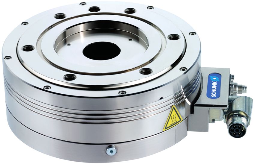
4.2 Description
The product is an electrical turning unit with torque motor and a
center bore. The center bore can be used as a media feed-through.
The product has an integrated position measuring system and a
temperature sensor.
The product must be operated using a drive controller. The
following operating modes can be set.
• Current-controlled
• Speed-controlled
• Position-controlled
The product is stored with the aid of a four point bearing. This
bearing is lubricated via one-time grease lubrication.
Under normal operating conditions, the grease lubrication is
sufficient for 20,000 operating hours, Maintenance intervals [} 49].
Rotary feed-through The variant with rotary feed-through (DDF), for sizes 170 and 210,
(DDF) variant is a combined pneumatic and electrical feed-through to supply
products on the ERS assembly.
Pneumatic holding For the variant with pneumatic holding brake, the rotary module is
brake variant held in the current position. To do this, the pneumatic holding
brake applies the rated torque for holding position at standstill.
NOTE
The pneumatic holding brake is not a service brake.
The pneumatic holding brake is actuated using the micro valve.
The micro valve is closed if there is no voltage at the micro valve.
In this state, the pneumatic holding brake is active. The micro
valve is opened if there is voltage at the micro valve. In this state,
the pneumatic holding brake is inactive.
Protection class IP54 With the protection class IP54 variant, an additional seal is built in
variant between the bearing flange and the rotor. During assembly, a seal
must also be attached in the groove on the top and bottom of the
ERS, to ensure the IP54 protection class is achieved.
26 04.00 | ERS 135 - 210 / 560V | Assembly and Operating Manual | en | 389064Design and description
Connection diagram
controller
UVW + PE encoder
supply encoder
voltage
encoder
8
encoder
plug connection basic
winding
2
temperature sensor KTY84
ERS schematic diagram
The schematic diagram shows the connection diagram of the
product between drive, encoder and drive controller.
04.00 | ERS 135 - 210 / 560V | Assembly and Operating Manual | en | 389064 27Assembly
5 Assembly
5.1 Installing and connecting
WARNING
Risk of injury due to unexpected movements!
If the power supply is switched on or residual energy remains in
the system, components can move unexpectedly and cause
serious injuries.
• Before starting any work on the product: Switch off the power
supply and secure against restarting.
• Make sure, that no residual energy remains in the system.
In order to achieve protection class IP 40, design the connection
structure so that no chips, cooling water or dirt can enter the
turning unit's connection area from the working area.
1. Protection class IP54 variant: insert seal into the groove,
Protection class IP54 variant [} 39].
2. Mount the product on a surface with good thermal conductive
properties, Mechanical connection [} 34].
3. Check the flatness of the mounting surface,
Mechanical connection [} 34].
4. Screw the turning unit to the machine/system,
Mechanical connection [} 34].
✓ Make sure that the interfaces to attachments are clean and
undamaged.
✓ Use suitable connecting elements (adapter plates) if
necessary.
✓ Observe the permissible depth of engagement.
✓ Observe the tightening torque for the mounting screws.
5. Connect the turning unit electrically,
Electrical connection [} 40].
✓ Screw the connection plug for power and sensor cable to
the turning unit.
✓ Connect the power and sensor cable to the drive controller.
6. Pneumatic holding brake variant: assemble and connect micro
valve, Installing the micro valve [} 31].
7. Assemble attachment output side.
28 04.00 | ERS 135 - 210 / 560V | Assembly and Operating Manual | en | 389064Assembly
5.1.1 Pneumatic holding brake variant
WARNING
Risk of injury when working on the micro valve!
Severe injuries can be caused with active power and compressed
air supply.
• Switch off the energy supply.
• Switch off the compressed air supply.
CAUTION
Damage to valve cartridges, valve cover and accessories!
Valve cartridge, valve cover and accessories can be damaged by
using tools.
• Only install or remove the valve cartridge, valve cover and
accessories by hand.
Comply with the following procedure when mounting the micro valve:
• If the micro valve is supplied as a complete component,
dismantle the micro valve into its individual components and
then install the individual components:
– Dismantling the micro valve into its individual components,
Dismantling micro valve [} 30].
– Installing the individual components,
Installing the micro valve [} 31].
• If the micro valve is supplied in individual components, install
the individual components, Installing the micro valve [} 31].
• Change the position of the screw cable,
Changing the position of the connection cable [} 32].
04.00 | ERS 135 - 210 / 560V | Assembly and Operating Manual | en | 389064 29Assembly
5.1.1.1 Dismantling micro valve
Dismantling micro valve
1. Undo the knurled screw on the valve cover (3).
NOTE
In valves with fixed covers, the valve cover with connection cable
cannot be removed.
2. Remove the valve cover (3) with connection cable and sound
absorber (4).
3. Unscrew the valve cartridge (2) from the swivel fitting (1).
30 04.00 | ERS 135 - 210 / 560V | Assembly and Operating Manual | en | 389064Assembly
5.1.1.2 Installing the micro valve
Micro valve
NOTE
Always carry out the assembly of the micro valve in the following
order, for example to avoid unscrewing the screw cap from the
valve cartridge if an accessory is fitted subsequently.
1. Screw the hollow screw of the swivel fitting (1) lightly into the
pneumatic unit (5), without tightening.
2. Turn the swivel fitting (1) to the desired position and hold it
firmly.
3. Tighten the hollow screw of the swivel fitting (1) in this
position, maximum tightening torque 1.5 Nm.
4. Screw the valve cartridge (2) into the swivel fitting (1) as far as
possible, maximum tightening torque 3 Nm.
5. Screw the sound absorber (4) into the valve cover (3),
maximum tightening torque: 3 Nm.
6. Put the valve cover (3) on the cartridge (2) with the connection
cable in the required position.
7. Push the valve cover (3) onto the cartridge (2) and screw tight
with the knurled nut onto the cartridge (2), maximum torque:
3 Nm.
8. Connect the pneumatic hose to the pneumatic connection of
the swivel fitting (1).
9. Push the Y‐distributor onto the M8 plug of the connection
cable and screw tight.
10. Push the cable extension onto the Y‐distributor and screw
tight.
11. Connect the cable extension to the electrical power supply,
Electrical connection [} 40].
12. Route the connection cable and cable extension and secure.
04.00 | ERS 135 - 210 / 560V | Assembly and Operating Manual | en | 389064 31Assembly
5.1.1.3 Changing the position of the connection cable
CAUTION
Risk of damage to the contacts!
The contacts can be damaged if the valve cover is screwed on
firmly and the alignment of the connection cable changed.
• Define the position of the connection cable when the valve
cover is put on.
Valve cover
1. Unscrew the knurled nut (1) of the valve cover (3) from the
valve cartridge (2).
2. Remove the valve cover (3) from the valve cartridge (2).
3. Put on the valve cover (3) again with the connection cable in
the required alignment and hold it in position.
4. Tighten the valve cover (3) on the valve cartridge (2) with the
knurled nut (1).
32 04.00 | ERS 135 - 210 / 560V | Assembly and Operating Manual | en | 389064Assembly
5.1.2 Rotary feed-through (DDF) variant
For the media feed-through, electrical connections and air
connections are available with the rotary feed-through (DDF)
variant.
Connections
1 Output-side connections
2 Input-side connections
3 Output-side air connections (Hose-free direct connection)
Air connection
1 Input-side air connection
04.00 | ERS 135 - 210 / 560V | Assembly and Operating Manual | en | 389064 33Assembly
5.2 Connections
5.2.1 Mechanical connection
NOTE
The ERS rotary unit must be mounted on a surface with good
thermal conductive properties, which corresponds to the
following sizes at minimum:
Size 135: 0.1024m2
Size 170: 0.0772m2
Size 210: 0.1296m2
Evenness of the The values apply to the whole mounting surface to which the
mounting surface product is mounted.
Requirements for evenness of the mounting surface (Dimensions in mm)
Edge length Permissible unevenness
< 100 < 0.02
> 100 < 0.05
NOTE
When mounting the product, the following must be observed:
• Position of the reference marks and thereby the zero pulse of
the sensor system
See catalog for dimensions to design the adapter plate, shape and
positional tolerances for radial and axial run-out.
Position of the reference marks and run-out accuracy acceptance
1 Centering surface for run- 2 Reference marks for zero
out accuracy acceptance pulse
34 04.00 | ERS 135 - 210 / 560V | Assembly and Operating Manual | en | 389064Assembly Centering groove 1 Centering groove With the rotary feed-through (DDF) variant, the run-out accuracy is accepted using the centering groove. 04.00 | ERS 135 - 210 / 560V | Assembly and Operating Manual | en | 389064 35
Assembly

                    Assembly view

                     Item Description                                       ERS
                                                            135             170         210
                     1       Mounting screws                M8              M10         M10
                             Tightening torque              24               48         48
                             [Nm]
                             Max. depth of                  10               10         10
                             engagement from
                             locating surface
                             [mm]
                     2       Centering pin                  Ø8              Ø10         Ø10
                     3       Centering pins                 Ø5              Ø5          Ø5
                     4       Mounting screws                M8              M10         M12
                             Tightening torque              24              48          84
                             [Nm]
                             Max. depth of                  13               14         18
                             engagement from
                             locating surface
                             [mm]

36         04.00 | ERS 135 - 210 / 560V | Assembly and Operating Manual | en | 389064
Assembly
5.2.1.1 Pneumatic holding brake variant
WARNING
Risk of injury due to unexpected movement of the machine/
system!
The pneumatic holding brake is not a service brake and only
applies the rated torque for holding position at standstill. With
active pneumatic holding brake and correspondingly high
moment load, components may move unexpectedly causing
severe injury.
• Do not use the pneumatic holding brake as a service brake.
• Do not use the pneumatic holding brake as a safety
component.
WARNING
Risk of injury when working on the micro valve!
Severe injuries can be caused with active power and compressed
air supply.
• Switch off the energy supply.
• Switch off the compressed air supply.
04.00 | ERS 135 - 210 / 560V | Assembly and Operating Manual | en | 389064 37Assembly
Rotary module with micro valve
1 Rotary module
2 Micro valve
3 Y distributor
With the pneumatic holding brake variant, both micro valves must
be mounted and used at all times. The micro valves are supplied
with electricity via the Y distributor.
NOTE
If both micro valves are not used, the time set in the parameter
sets for filling the pistons is exceeded.
38 04.00 | ERS 135 - 210 / 560V | Assembly and Operating Manual | en | 389064Assembly
5.2.1.2 Protection class IP54 variant
Sealing groove
In order to achieve protection class IP54, a seal (NBR70 O-ring)
must be inserted at the top and bottom of the product.
ID number of the O-ring
Size ID
NBR70 O-ring 135 170 210
Ø33x2 9942376 – –
Ø74x2 9907467 – –
Ø50x2 – 9871512 –
Ø103x2 – 9907464 –
Ø60x2 – – 9611058
Ø140x2 – – 9937935
04.00 | ERS 135 - 210 / 560V | Assembly and Operating Manual | en | 389064 39Assembly
5.2.2 Electrical connection
DANGER
Risk of fatal injuries due to electric shock!
If the power supply is not switched off before working on the
product, the drive controller is not separated from the power
cables, or cables are connected incorrectly, fatal injury may be
caused from electric shock.
• Switch off energy supply before carrying out all assembly,
adjustment and maintenance work and secure against re-
connection.
• Only allow qualified electricians to work on electrical
automated systems.
• Disconnect the drive controller from the power supply. The
intermediate circuit capacitors must be discharged. Wait for
approx. 15 minutes for the capacitors to discharge.
• Observe order when connecting the cables (first ground cable,
then conductors).
CAUTION
Damage to the connection cable is possible!
If the following preconditions are not observed when installing
the connection cables, the connection cable may become
damaged
• Install connection cables free from tensile and torsion loads. If
necessary, use cable guide chains.
• Comply with the minimum bending radius (7.5 times the cable
diameter).
• Install the connection cable so that the motor's range of
rotation and function are not impaired.
CAUTION
Material damage possible to lines!
If the following prerequisites are not observed for installation of
lines, the lines may be damaged.
• When installing the lines, observe the specifications in the line
manufacturer data sheet.
• During operation of the axes across the full stroke too, make
sure that the lines do not become crushed, sheared or torn off.
• Install the power cable and measuring system lines in separate
cable tracks.
40 04.00 | ERS 135 - 210 / 560V | Assembly and Operating Manual | en | 389064Assembly
Connection
assignment, power
connector
Power connector, M17
Pin Signal Pin Signal
PE Ground/motor housing 4 N. C.
1 U 5 Temperature sensor 1
2 V 6 Temperature sensor 2
3 W
Sensor plug
connection
assignment
Sensor plug, M9
Pin Signal Pin Signal
1 A (SIN +) 5 Z (Ref +)
2 /A (SIN -) 6 /Z (Ref -)
3 B (COS +) 7 GND
4 /B (COS -) 8 Vcc
04.00 | ERS 135 - 210 / 560V | Assembly and Operating Manual | en | 389064 41Assembly
Bosch power and The cable colors and designations in the following tables apply to
sensor cables the SCHUNK connection cable.
connection Connection assignment of the blue power cable for Bosch Rexroth IndraDrive
assignment
Function Signal Cable designation
Power U Black A1 (U)
V Black A2 (V)
W Black A3 (W)
PE Green /Yellow
Temperature sensor T1 Red
T2 Blue
Connection assignment of the white sensor cable for Bosch IndraDrive Basic/Advanced
Function Signal Pin allocation – 15-pin Sub-D
socket
Encoder /Z (Ref -) Pin 3
Z (Ref +) Pin 4
/B (COS -) Pin 5
B (COS +) Pin 6
A (SIN +) Pin 7
/A (SIN -) Pin 8
GND Pin 10
Vcc Pin 12
Connection assignment of the white sensor cable for Bosch Rexroth IndraDrive CS
Function Signal Pin allocation – 15-pin Sub-D
socket
Encoder A (SIN +) Pin 2
/A (SIN -) Pin 3
GND Pin 4
B (COS +) Pin 5
/B (COS -) Pin 6
Z (Ref +) Pin 9
/Z (Ref -) Pin 10
Vcc Pin 12
42 04.00 | ERS 135 - 210 / 560V | Assembly and Operating Manual | en | 389064Assembly
Siemens power and Connection assignment of the power cable for Siemens Sinamics (connection to drive
controller)
sensor cables
connection Function Signal Pin allocation – Siemens
assignment circular plug
Power U U2
V V2
W W2
PE Earth
Connection assignment of the white sensor cable for Siemens Sinamics
Function Signal Pin allocation – 12-pole M23
pin terminal
Encoder /B (COS -) Pin 1
Vcc Pin 2
Z (Ref +) Pin 3
/Z (Ref -) Pin 4
A (SIN +) Pin 5
/A (SIN -) Pin 6
B (COS +) Pin 8
GND Pin 10
04.00 | ERS 135 - 210 / 560V | Assembly and Operating Manual | en | 389064 43Assembly
5.2.2.1 Pneumatic holding brake variant
CAUTION
Damage to the cable is possible.
The bending radius of the cable is not allowed to be less than the
minimum amount:
• Static: 10 times the cable diameter.
• Dynamic: 15 times the cable diameter, suitable for cable tracks.
NOTE
Route and secure the connection cable so there are no tensile and
twisting forces on the valve cover. Tensile and twisting forces can
cause the screw cap to come loose and lead to contact problems.
PIN allocation M8 plug and cable color cable extension
PIN Cable color Assignment
1 Brown n.c.
3 Blue GND
4 Black Control voltage, + 24 VDC
Screw cap with LED:
If the connection cable of the micro valve has been connected
correctly to the electrical power supply, the LED in the screw cap
will light up when the 24 VDC voltage is applied.
Connection to Bosch Rexroth IndraDrive
Terminal Cable color Assignment
X6-3 Black +24 VDC
X6-4 Blue GND
Connection to Siemens Safe Brake Relay
Terminal Cable color Assignment
BR+ Black +24 VDC
BR- Blue GND
44 04.00 | ERS 135 - 210 / 560V | Assembly and Operating Manual | en | 389064Assembly
5.2.2.2 Rotary feed-through (DDF) variant
Rotary feed-through electrical connections
A M8 socket, 3-pin
B M8 connector, 3-pin
1 +24V 4 Signal
3 GND
With the rotary feed-through (DDF) variant, there are
8 connections on the input side and 8 connections on the output
side of the product (in each case 4 sleeves and 4 connection
plugs). If the voltage is applied on the input side at a connection,
the voltage is available at all connection plugs.
04.00 | ERS 135 - 210 / 560V | Assembly and Operating Manual | en | 389064 45Troubleshooting
6 Troubleshooting
6.1 Product not turning
Possible cause Corrective action
Interruption in the supply line. Check the supply lines for defects.
Check electrical connection.
Electrical connection [} 40]
No motion release Check the settings of the drive controller.
Drive controller defective. DANGER Risk of fatal injuries due to electric shock!
Check whether there is voltage at the drive
controller's output.
If there is no voltage:
Check connection assignment, see drive controller
operating manual.
Electrical connection [} 40]
Communication between higher- Check communication.
level controller and converter
interrupted.
Rotor mechanically blocked. Check mechanics.
Check that the mounting surface is flat.
Mechanical connection [} 34]
Encoder defective. Check encoder and encoder connection.
If defective:
Replace component or send it to SCHUNK for repair.
Short-circuit between turns in the Check terminal resistances with a multimeter.
motor. Technical data [} 17]
If the difference between the individual motor
phases is larger than 0.1 Ohm:
Replace component or send it to SCHUNK for repair.
Short-circuit to ground due to Check protective conductor.
moisture or short-circuit to ground If the product has a ground leak while the power
due to electrical malfunction. cable is disconnected:
Check the electrical connections and connectors for
ground leakage.
Replace component or send it to SCHUNK for repair.
Incorrect phase connections. Check electrical connection.
Electrical connection [} 40]
46 04.00 | ERS 135 - 210 / 560V | Assembly and Operating Manual | en | 389064Troubleshooting
Possible cause Corrective action
Drive controller settings are Check the parameters and setting values, see
incorrect. operating manual for the drive controller.
Motor phases or encoder signals Check electrical connection.
confused. Electrical connection [} 40]
Check the encoder signals and the shielding of the
sensor cable.
6.2 Product is having control difficulties.
Possible cause Corrective action
Driver controller is not optimally Check the settings (direction of rotation of motor
adjusted. and encoder direction of counting).
6.3 Product is vibrating.
Possible cause Corrective action
Load inertia is too high. Check the dimensioning.
Reduce the load.
Check the settings on the drive controller.
Drive controller is not optimally Check the settings on the drive controller.
adjusted.
6.4 Bearing noise
Possible cause Corrective action
Incorrect assembly. Check that the mounting surface is flat.
Mechanical connection [} 34]
Bearing defective due to overload. Replace component or send it to SCHUNK for repair.
6.5 Error message for the winding temperature
Possible cause Corrective action
Electrical connection to the Check resistance between drive controller and
temperature sensor faulty. temperature sensor.
If necessary:
Replace electrical connection.
Temperature sensor defective. Check the resistance of the temperature sensor.
If the resistance at room temperature is larger than
630 Ohm:
Replace component or send it to SCHUNK for repair.
Thermal motor overload. Reduce the load.
Mount the motor on heat-conducting materials to
dissipate excess motor heat.
04.00 | ERS 135 - 210 / 560V | Assembly and Operating Manual | en | 389064 47Troubleshooting
Possible cause Corrective action
Rotor mechanically blocked. Check mechanics.
Check that the mounting surface is flat.
Mechanical connection [} 34]
Encoder signals are faulty; encoder Check the encoder's power supply.
line shielding is not connected. Check the encoder signals and the shielding of the
sensor cable.
Electrical connection to the Check resistance between drive controller and
temperature sensor faulty. temperature sensor.
If necessary:
Replace the electrical connection.
Motor overload. Check the dimensioning.
Reduce the load.
Overvoltage or undervoltage is Check the settings on the drive controller.
present. Check the output power supply.
48 04.00 | ERS 135 - 210 / 560V | Assembly and Operating Manual | en | 389064Maintenance
7 Maintenance
7.1 Maintenance intervals
DANGER
Risk of fatal injuries due to electric shock!
If the electrical connections are released from the live product,
arcing may be the result.
• Before working on the product, switch off the energy supply.
• Only have work performed on the product by an expert
electrician.
Interval [Mio. cycles] Maintenance work
for
ERS 135 - 210
2.5 Check bearings for noise,
Servicing the product [} 49].
2.5 Dry clean all parts thoroughly, check for
damage and wear,
Servicing the product [} 49].
20 Grease all bearings,
Servicing the product [} 49].
20 Replace all seals,
Disassembly and assembling [} 50].
7.2 Servicing the product
NOTE
For maintenance work or repairs, send the product along with a
repair order to SCHUNK.
visual inspection
The regular visual inspection of all supply lines is required for the
perfect operation of the product.
1. Perform a visual inspection on all supply cables.
2. If supply lines are defective, put the machine/system out of
operation immediately.
3. Replace damaged connection cables.
04.00 | ERS 135 - 210 / 560V | Assembly and Operating Manual | en | 389064 49Maintenance
Acoustic bearing inspection
Bearing noise Further procedure
Smooth noise Product can continue to be operated.
Rough grinding noise The motor is not set up correctly:
• Check the evenness at mounting
surfaces.
Mechanical connection [} 34]
Loud and rough noise or The motor is not set up correctly:
motor not running • Check the evenness at mounting
smoothly surfaces.
Mechanical connection [} 34]
Bearings defective:
• Replace component or send it to
SCHUNK for repair.
7.3 Disassembly and assembling
This product must not be disassembled for maintenance.
CAUTION
Material damage due to improper disassembly!
Incorrect works can cause damage to the mechanics and internal
electronics.
• Disassembly or opening of the product is not permitted.
• Only allow SCHUNK to repair the product.
50 04.00 | ERS 135 - 210 / 560V | Assembly and Operating Manual | en | 389064Translation of original declaration of incorporation
8 Translation of original declaration of incorporation
in terms of the Directive 2006/42/EG, Annex II, Part 1.B of the European Parliament and of
the Council on machinery.
Manufacturer/ SCHUNK GmbH & Co. KG Spann- und Greiftechnik
Distributor Bahnhofstr. 106 – 134
D-74348 Lauffen/Neckar
We hereby declare that on the date of the declaration the following partly completed
machine complied with all basic safety and health regulations found in the directive
2006/42/EC of the European Parliament and of the Council on machinery. The declaration
is rendered invalid if modifications are made to the product.
Product designation: Electrical turning unit with torque motor / ERS 135 - 210 /
560V / electric
ID number 0310146 ... 0310224
The product also complies with LVD Directive (2014/35/EU).
Applied harmonized standards, especially:
EN ISO 12100:2010 Safety of machinery - General principles for design -
Risk assessment and risk reduction
EN 60204-1: 2006 Safety of machinery – Electrical equipment of machines, Part 1:
General requirements
DIN EN 61000-6-2: Electromagnetic compatibility (EMC) - Part 6-2: Generic
2011-06 standards- Immunity for industrial environments
EN 61000-6-4:2007 + Electromagnetic compatibility (EMC) - Part 6-4: Generic standards
A1:2011 - Emission standard for industrial environments
(IEC 61000-6-4:2006 + A1:2010);
ISO 9409-1:2004-03 Manipulating industrial robots - Mechanical interfaces - Part 1: plates
The partly completed machine may not be put into operation until conformity of the
machine into which the partly completed machine is to be installed with the provisions of
the Machinery Directive (2006/42/EC) is confirmed.
The manufacturer agrees to forward on demand the relevant technical documentation for
the partly completed machinery in electronic form to national authorities.
The relevant technical documentation according to Annex VII, Part B, belonging to the
partly completed machinery, has been created.
Person authorized to compile the technical documentation:
Robert Leuthner, Address: see manufacturer's address
Lauffen/Neckar, January 2021 Dr.-Ing. Manuel Baumeister,
Technology & Innovation,
Mechatronics & Sensors
04.00 | ERS 135 - 210 / 560V | Assembly and Operating Manual | en | 389064 51You can also read