Segway Personal Transporter Service Manual - i2 SE i2 SE Patroller x2 SE x2 SE Turf x2 SE Patroller - March 2014
←
→
Page content transcription
If your browser does not render page correctly, please read the page content below
Segway® Personal Transporter
       Service Manual
         i2 SE
         i2 SE Patroller
         x2 SE
         x2 SE Turf
         x2 SE Patroller

          March 2014
            24019-00001 aa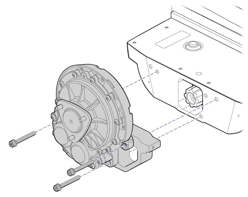
WARNING!
     To replace parts on the Segway Personal Transporter, you must read and follow all instructions
     and warnings in this Service Manual. Failure to do so could result in serious injury or death.

ii                                                                            Segway Personal Transporter SE Service Manual
Copyright, Disclaimer, Trademarks, Patent, and Contact Information
Copyright © 2014 Segway Inc. All rights reserved.

Trademarks
Segway owns a number of trademarks including, but not limited to, Segway and the Segway "Rider Design" logo that have been
registered in the United States and in other countries. Those trademarks followed by ® are registered trademarks of Segway.
All other marks are trademarks or common law marks of Segway. Failure of a mark to appear in this guide does not mean that
Segway does not use the mark, nor does it mean that the product is not actively marketed or is not significant within its relevant
market. Segway reserves all rights in its trademarks. All other trademarks are the property of their respective companies.

Segway Patent Information
The Segway PT is covered by U.S. and foreign patents.
For a patent listing, see http://www.segway.com/downloads/pdfs/patents.pdf.

Contact Information
For support, please contact the company from which you bought the Segway product. For a listing of Authorized Segway Dealers
and Distributors, refer to the Segway website at http://www.segway.com.

Segway Customer Care: 866-4SEGWAY (866-473-4929)
Fax: 603-222-6001
E-mail: technicalsupport@segway.com
Website: http://www.segway.com

Segway Personal Transporter SE Service Manual                                                                                   iii
iv Segway Personal Transporter SE Service Manual
Contents
     Copyright, Disclaimer, Trademarks, Patent, and Contact Information........................................................ iii

General Safety Precautions..................................................................................................ix
     Safety Conventions........................................................................................................................................ ix
     Important Safety Notices.............................................................................................................................. ix

Introduction....................................................................................................................... 0–1
     Purpose...................................................................................................................................................... 0–1
     Audience..................................................................................................................................................... 0–1
     Certification............................................................................................................................................... 0–1
     Organization...............................................................................................................................................0–2
     Terminology................................................................................................................................................0–3
     Customer Replaceable Kits and Technician Replaceable Parts...............................................................0–3
     Related User Materials...............................................................................................................................0–3
     Parts Diagram............................................................................................................................................0–4

1 LeanSteer.......................................................................................................................1–1
     Handlebar....................................................................................................................................................1–4
     LeanSteer Frame.........................................................................................................................................1–5
     LeanSteer Stem..........................................................................................................................................1–6
     InfoKey Controller.......................................................................................................................................1–7
     InfoKey Dock...............................................................................................................................................1–7
     InfoKey Controller Battery..........................................................................................................................1–8

2 Mats............................................................................................................................... 2–1
     Mats............................................................................................................................................................ 2–2

3 Batteries....................................................................................................................... 3–1
     Batteries..................................................................................................................................................... 3–2

4 Tire/Wheel Assembly.................................................................................................. 4–1
     i2 SE Wheel Assembly................................................................................................................................ 4–2
     x2 SE Wheel Assembly............................................................................................................................... 4–3
     x2 SE Turf Wheel Assembly........................................................................................................................4–4
     x2 SE Turf Hub Adapter.............................................................................................................................. 4–5
     i2 SE Tire Tube............................................................................................................................................4–6

Segway Personal Transporter SE Service Manual                                                                                                                          v
Contents
5 Fenders.......................................................................................................................... 5–1
i2 SE Fender................................................................................................................................................ 5–2
x2 SE Fender............................................................................................................................................... 5–3
x2 SE Fender Frame................................................................................................................................... 5–4
6 Powerbase Trim............................................................................................................ 6–1
Gearbox Cover............................................................................................................................................ 6–2
Console Cover............................................................................................................................................ 6–3
Front and Rear Fascia.................................................................................................................................6–4
7 Gearbox..........................................................................................................................7–1
Gearbox...................................................................................................................................................... 7–2
8 Serviceable Powerbase................................................................................................ 8–1
Establishing a Serviceable Powerbase...................................................................................................... 8–2
9 Console......................................................................................................................... 9–1
Console Components................................................................................................................................ 9–2
Radio Board................................................................................................................................................ 9–3
Console.......................................................................................................................................................9–4
Power Board............................................................................................................................................... 9–5
Interconnect Board.................................................................................................................................... 9–6
AC Input Filter............................................................................................................................................ 9–7
Pivot Assembly........................................................................................................................................... 9–9
Front Light Pipe........................................................................................................................................ 9–10
10 Chassis Cover............................................................................................................. 10–1
Chassis Cover........................................................................................................................................... 10–2
11 CU Board...................................................................................................................... 11–1
CU Board................................................................................................................................................... 11–2
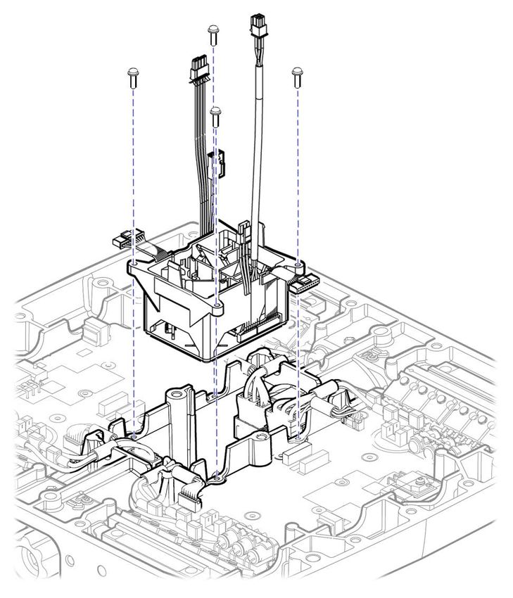
12 Balance Sensor Assembly..........................................................................................12–1
Balance Sensor Assembly........................................................................................................................12–2
13 Motor............................................................................................................................13–1
Motor.........................................................................................................................................................13–2
Elastomer Bushing................................................................................................................................... 13–4
14 Powerbase Chassis.....................................................................................................14–1
Powerbase Chassis...................................................................................................................................14–2
vi Segway Personal Transporter SE Service ManualContents
A Post-Service Tests........................................................................................................ A–1
Startup Test................................................................................................................................................ A–1
Standard Check.......................................................................................................................................... A–1
Operational Test......................................................................................................................................... A–1
B Parts List....................................................................................................................... B–1
Customer Replaceable Kits....................................................................................................................... B–1
Technician Replaceable Parts....................................................................................................................B–2
C Fasteners....................................................................................................................... C–1
D Tools and Equipment...................................................................................................D–1
E Glossary........................................................................................................................ E–1
Segway Personal Transporter SE Service Manual viiContents viii Segway Personal Transporter SE Service Manual
General Safety Precautions
Safety Conventions
The following safety messaging conventions are used throughout this document:

              WARNING!               Warns you about actions that could result in death or serious injury.
               CAUTION!              Warns you about actions that could result in minor or moderate injury.
                                     Indicates information considered important, but not related to personal injury. Examples
                NOTICE
                                     include messages regarding possible damage to the PT or other property, or usage tips.

Important Safety Notices
Read and follow all safety notices.

General
   WARNING!
    • Failure to follow these safety precautions could lead to electrical shock, serious injury, death, or damage to property.
     •    To replace parts on the Segway PT, you must read and follow all instructions and warnings in this Service Manual.
     •    Always power off the Segway PT before performing any maintenance or installing any part or accessory.
     •    Always unplug the AC power cord before performing any maintenance or installing any part or accessory.

Batteries
   WARNING!
    • Do not use the battery if the battery casing is broken or if the battery emits an unusual odor, smoke, or excessive
       heat, or leaks any substance. Avoid contact with any substance seeping from the battery. Batteries contain toxic and
       corrosive materials that could cause serious injury.
     •    As with all rechargeable batteries, do not charge near flammable materials. When charging, the batteries heat up and
          could ignite a fire.
     •    Keep out of reach of children and pets. Exposure to battery voltage could result in death or serious injury.
     •    Observe and follow all safety information on the warning label found on the battery.
     •    Use only Segway-approved charging devices to charge the batteries.
     •    Do not attempt to open batteries. Do not insert any object into the batteries or use any device to pry at the battery
          casing. If you insert an object into any of the battery ports or openings you could suffer electric shock, injury, burns,
          or cause a fire. Attempting to open the battery casing will damage the casing and could release toxic and harmful
          substances, and will render the battery unusable.
     •    Do not submerge the PT, batteries, or powerbases in water. Do not use a power washer or high-pressure hose to clean
          a PT. Avoid getting water into any of the connectors. Avoid exposing the Segway PT to heavy downpours or extended
          periods of heavy rain. If you suspect the batteries or powerbase have been submerged or experienced water intrusion,
          call Segway Technical Support immediately at 1-866-473-4929, prompt #2. Until you receive further instructions, store
          the PT upright, outdoors, and away from flammable objects. Failure to do so could expose you to electric shock, injury,
          burns, or cause a fire.
     •    Comply with all local and federal or individual country laws when disposing of and transporting Segway PT batteries.
     •    Failure to adhere to these warnings could lead to serious injury, death, fire, or damage to property.

Segway Personal Transporter SE Service Manual                                                                                         ix
General Safety Precautions
Fasteners
WARNING!
• Use only Segway-approved fasteners. Other fasteners may not perform as expected and may come loose.
• Do not tighten or reuse any fastener except the screws used to attach the batteries, wheel nuts, and LeanSteer frame.
Instead, when any other fastener is loose or removed, replace the fastener with a new Segway-approved fastener. See
“Fasteners,” page C–1, for more information.
• Before using a fastener, make certain the fastener is the correct size and type with any necessary washer and thread
lock in place (see Table C–1, p. C–2).
• Since the pre-applied thread lock compound is intended for single use only, reuse of fasteners is not permitted with the
exception of the wheel nuts, battery fasteners, and LeanSteer frame fasteners.
• Do not attempt to repair any stripped or damaged screw hole. Instead, replace the part. If a replacement part is not
available, do not reassemble.
• Insert fasteners slowly and carefully. Do not cross-thread or over-tighten fasteners. Tighten only to the prescribed
torque.
• At the factory, Segway installs self-tapping fasteners intended for one-time use only. Service replacement fasteners are
not self-tapping and, therefore, may differ slightly in appearance from the comparable factory-installed fasteners.
• Failure to adhere to these warnings could lead to serious injury or death or damage to property.
Eye Protection
WARNING!
• When procedures require the use of safety glasses (such as those in which a mallet or solvent is used), failure to wear
eye protection could result in serious injury.
ESD Procedures
CAUTION!
• When a repair involves opening the console or chassis cover, best-practice electrostatic discharge (ESD) control
procedures must be followed. Failure to follow ESD procedures could result in personal injury or damage to property.
SOLVENTS
CAUTION!
• This manual refers to the use of isopropyl alcohol and ammonia or ammonia-based window cleaner in certain cleaning
procedures. Use of any other type of solvent is not allowed.
Questions
WARNING!
• If you have any questions about the instructions in this guide, please contact a Segway Service Representative to avoid
confusion leading to serious injury or death or damage to property.
x Segway Personal Transporter SE Service ManualIntroduction
Purpose
The purpose of this manual is to provide instructions for servicing the Segway
Personal Transporter (Segway PT) models i2 SE/Patroller, x2 SE/Patroller, and
x2 SE Turf.
Audience
Chapters 1 – 8 of this manual are written for either customers or Segway
Certified Service Technicians working under agreement with Segway Inc.
Chapters 9 – 14 of this manual are written only for Segway Certified Service
Technicians working under agreement with Segway Inc. See page 8–3 for
more information.
Certification
Becoming a Segway Certified Service Technician involves a four-level
certification process. The service technician will be required to undergo
training at each level. Upon satisfactory completion of this training, the service
technician becomes certified to repair the Segway PT parts and assemblies
according to the following scheme:
Table 0–1: Certification Levels
Level Parts and Assemblies Certified to Maintain Instructions
1 • Customer Replaceable Parts
−− LeanSteer Frame Chapter 1
−− Mats Chapter 2
−− Batteries Chapter 3
−− Tire/Wheel Assembly Chapter 4
−− Fender Chapter 5
−− Powerbase Trim Chapter 6
−− Gearbox Chapter 7
• Serviceable Powerbase Chapter 8
2 • All Level 1 (see above) See above
• Console Chapter 9
−− Radio Board “
−− Console “
−− Power Board “
−− Interconnect Board “
−− AC Input Filter “
−− Pivot Assembly “
−− Front Light Pipe “
Segway Personal Transporter SE Service Manual 0–1Introduction
Table 0–1: Certification Levels (cont.)
Level Parts and Assemblies Certified to Maintain Instructions
3 • All Level 1 and Level 2 (see above) See above
• Embedded Systems
−− Chassis Cover Chapter 10
−− CU Board Chapter 11
−− Balance Sensor Assembly (BSA) Chapter 12
−− Motor Chapter 13
−− Powerbase Chassis Chapter 14
4 • All Level 1, Level 2, and Level 3 (see above) See above
• Diagnostics (with special tools)
Organization
This manual organizes service instructions into two general categories:
• Instructions intended for both customers and service technicians
(Chapter 1 – Chapter 8)
• Instructions intended for service technicians only
(Chapter 9 – Chapter 14)
The instructions in Chapter 9 – Chapter 14 describe procedures for replacing parts
after having established a Serviceable Power Base (SPB), which is described in
Chapter 8.
Table 0–2: Chapter Descriptions
Chapter Description
page ix Safety information. Read before servicing the Segway PT.
page 0–4 Exploded view of the Segway PT component parts.
Chapter 1 LeanSteer Frame and LeanSteer Stem installation and removal procedures.
Chapter 2 Mat installation and removal procedures.
Chapter 3 Li-ion Battery installation, removal, and troubleshooting procedures.
Chapter 4 Tire/Wheel Assembly installation and removal procedures.
Chapter 5 Fender and Fender Frame installation and removal procedures.
Chapter 6 Powerbase Trim (Fascia) installation and removal procedures.
Chapter 7 Gearbox installation and removal procedures.
Chapter 8 Serviceable Power Base definition and description.
Chapter 9 Console and related components installation and removal procedures.
Chapter 10 Chassis cover installation and removal procedures.
Chapter 11 CU Boards installation and removal procedures.
Chapter 12 Balance Sensor Assembly installation and removal procedures.
Chapter 13 Motor installation and removal procedures.
Chapter 14 Powerbase Chassis replacement procedure.
Appendix A Post-Service Tests to be performed after servicing the Segway PT.
Appendix B Parts Lists for the Segway PT.
Appendix C Fastener descriptions and specifications.
Appendix D Tools and diagnostic equipment necessary to properly service a Segway PT.
Appendix E Definitions of product-specific words used in this manual.
0–2 Segway Personal Transporter SE Service ManualIntroduction
Terminology
Throughout this manual, the term “model x2” refers to both the x2 and x2 Turf
models unless otherwise noted. All i2/x2 procedures are valid in all SE and
Patroller models unless otherwise noted.
Customer Replaceable Kits and Technician Replaceable Parts
Subassemblies qualified in this manual as Customer Replaceable may be
installed by the customer. Otherwise, subassemblies are qualified as installable
only by a Certified Service Technician.
A subassembly that is available as a replaceable kit is shipped in a box and
includes all parts and fasteners needed to install the subassembly. These kits
are listed under the heading Replaceable Kits on the first page of each chapter.
All parts included in a Replaceable Kit should be replaced.
When individual parts of a subassembly are available for replacement, these
parts are shipped without fasteners and are intended for installation only by a
Certified Service Technician. These parts are listed under the heading Technician
Replaceable Parts on the first page of each chapter.
Related User Materials
The following additional materials may be needed for reference during service:
• User Manual: Segway Personal Transporter (PT) i2 SE, x2 SE, x2 SE Turf
Please check the Segway website (www.segway.com) for updates to the User
Manual, or contact Segway to confirm you have on hand the most recent service
publications.
Segway Personal Transporter SE Service Manual 0–3Introduction
Parts Diagram
Handlebar Clamp InfoKey
21861-00001 (Patroller) 21064-00001 (Programmed)
21065-00001 (Unprogrammed)
Handlebar Handlebar Clamp
20443-00001 20046-00001 (Standard)
InfoKey Dock
20533-00001
x2 Fender x2 Components
x2 Fender Frame 20798-00002 (Left)
23489-00001 20798-00001 (Right)
LeanSteer Frame
23512-00001 (Standard) x2 Wheel
(Patroller) 23548-00001 23725-00001
x2 Hubcap
23537-00001
Mat
23554-00001 (Standard)
23578-00001 (Comfort)
Gearbox Cover Console Trim
20152-00001 23478-00001 LeanSteer Stem
23508-00001 (Standard)
23507-00001 (Patroller)
Stem Cap
23519-00001
Front Console Trim
23399-00001
Front Fascia
23550-00001
i2 Fender
20190-00001
Rear Fascia
23550-00002
i2 Hubcap
20325-00001
i2 Wheel
Battery
20162-00001
20967-00001
0–4 Segway Personal Transporter SE Service Manual1 LeanSteer
This chapter describes installation and removal procedures for the LeanSteer Applies to Models
Frame, LeanSteer Stem, and handlebar. The LeanSteer assembly pivots at the
i2 SE, x2 SE, x2 SE Turf
base to control left/right movement of the PT.
WARNING! Qualifications
• Failure to follow these safety precautions could lead to electrical shock,
Customer Replaceable
serious injury, death, or damage to property.
• Read all instructions. Customer Replaceable Kits
• Power off the Segway PT. Handlebar Clamp Kit (20954-00001)
• Unplug the Segway PT. 1 Handlebar Clamp
• The LeanSteer Frame and LeanSteer Stem must be properly attached 3 Fasteners
and secured. Failure to properly attach the LeanSteer components
and/or maintain proper torque on the fasteners could result in Handlebar Kit (20955-00001)
machine malfunction and could cause personal injury or damage to
1 Handlebar
the Segway PT. Using the Segway PT without properly assembling
the LeanSteer components and/or maintaining proper torque on the
fasteners could lead to an unexpected change in steering and could
result in serious injury and/or damage to the Segway PT from loss of
control, collisions, and falls.
• Check the tightness of the fasteners connecting the LeanSteer Stem
to the Pivot Base every time the LeanSteer Stem is removed and
reinstalled.
When to Replace
You need to replace the LeanSteer frame if any part is bent or otherwise broken.
Segway Personal Transporter SE Service Manual 1–1LeanSteer
Standard LeanSteer Frame
M4 x 20 SHCS
20306-00001
Grip Trim
Handlebar Clamp
18892-00001
20046-00001 (Standard)
Handlebar Tube
20045-00001
Upper LeanSteer Tube
20048-00001 (Standard)
Tube Bushing
Handlebar Stop 23511-00001
20041-00001
Height Adjust Knob
20753-00001
Washer
20751-00001
Lower LeanSteer Tube
Wedge 23509-00001
20042-00001
#6-19x19mm PHCS
Bolt Trim 23558-00001
23516-00001 (Standard)
Washer Plate End Cap
23545-00001 (Standard) 23541-00001
Figure 1–1: Standard LeanSteer Frame Components
1–2 Segway Personal Transporter SE Service ManualLeanSteer
Patroller LeanSteer Frame
M4 x 20 SHCS
20306-00001
Grip Trim
18892-00001
Handlebar Clamp
21861-00001 (Patroller) Handlebar Tube
20045-00001
Upper LeanSteer Tube
21791-00001 (Patroller)
Handlebar Stop
20041-00001
Tube Bushing
23511-00001
Height Adjust Knob
20753-00001
Washer
20751-00001
Lower LeanSteer Tube Wedge
23509-00001 20042-00001
#6-19x19mm PHCS
Bolt Trim 23558-00001
23545-00002 (Patroller)
Washer Plate End Cap
23545-00002 (Patroller) 23541-00001
Figure 1–2: Patroller LeanSteer Frame Components
Segway Personal Transporter SE Service Manual 1–3LeanSteer
Handlebar
Removal Handlebar
Tool Required: 3 mm hex wrench
1. Make sure the Segway PT is powered off and
unplugged.
2. Using a 3 mm hex wrench, remove the three
fasteners that secure the Handlebar Clamp to the
LeanSteer Frame. See Figure 1–3.
3. Remove the Handlebar and Handlebar Clamp from Handlebar Clamp
the LeanSteer Frame.
20306-00001
Installation 2.0 N-m (18 in-lbf)
Tools Required: 3 mm hex wrench
Torque wrench Figure 1–3: Installing and Removing the Handlebar
1. Make sure the Segway PT is powered off and
unplugged.
2. Align the Handlebar in place against the LeanSteer
Frame using the alignment guides. See Figure 1–4.
3. Position the Handlebar Clamp against the
Handlebar.
4. Insert the three fasteners through the Handlebar
Clamp and into the LeanSteer Frame.
5. Using a 3 mm hex wrench, alternate between
the three fasteners, evenly tightening in small
increments.
6. Check to ensure that the gap between the Handlebar
Clamp and the LeanSteer Frame is even and is
Figure 1–4: Aligning the Handlebar
equidistant between top and bottom. Torque to
2.0 N-m (18 in-lbf).
7. Perform post-service tests (page A–1).
1–4 Segway Personal Transporter SE Service ManualLeanSteer
LeanSteer Frame
Removal 23517-00001
Tool Required: 5 mm hex wrench 11.0 N-m (8.1 ft-lbf)
LeanSteer Frame
1. Make sure the PT is powered off and unplugged.
2. Using a 5 mm hex wrench, remove the two fasteners LeanSteer
holding the LeanSteer Frame to the LeanSteer Stem Stem
(see Figure 1–5), while supporting the LeanSteer
Frame.
3. Remove the LeanSteer Frame.
Installation
Tools Required: 5 mm hex wrench
Torque wrench
1. Make sure the PT is powered off and unplugged.
2. Place the LeanSteer Frame onto the LeanSteer Stem
(see Figure 1–5).
3. Using a 5 mm hex wrench, install the two fasteners.
Torque to 11.0 N-m (8.1 ft-lbf).
Figure 1–5: LeanSteer Frame
4. With the PT powered down (OFF), lean the LeanSteer
Frame fully left and right, until it touches each
fender (see Figure 1–6).
5. Ensure the LeanSteer Frame returns to a straight,
upright position. If it is not vertical, follow the
instructions on page 1–6 to remove and install the
LeanSteer Stem.
6. Check the fasteners to be sure they are tight.
NOTICE
Check the fasteners at least monthly to be sure they
remain tight. If they are loose, tighten the fasteners
to 11.0 N-m (8.1 ft-lbf).
7. Perform post-service tests (page A–1).
Figure 1–6: Check LeanSteer Frame
Segway Personal Transporter SE Service Manual 1–5LeanSteer
LeanSteer Stem
Removal
Tool Required: T-30 6-lobe wrench
1. Make sure the PT is powered off and unplugged.
LeanSteer Stem
2. Remove the LeanSteer Stem Cap (see Figure 1–7).
3. Using a T-30 6-lobe wrench, remove the four
fasteners.
4. Slide the LeanSteer Stem off the pivot base.
LeanSteer
Stem Cap
Installation
Tools Required: T-30 6-lobe wrench Pivot Base
Torque wrench
20539-00001
1. Make sure the PT is powered off and unplugged. 11 N-m (8.1 ft-lbf)
2. Slide the LeanSteer Stem onto the pivot base (see Figure 1–7: LeanSteer Stem
Figure 1–7).
NOTICE
The Standard LeanSteer Stem must be used Standard Patroller
with the Standard LeanSteer Frame, and the
Patroller LeanSteer Stem must be used with the
Patroller LeanSteer Frame. Standard and Patroller
components cannot be used together.
3. Using a T-30 6-lobe wrench, install the four
fasteners, but do not tighten completely.
4. Make sure the LeanSteer Stem is vertical.
5. Tighten the fasteners to 11 N-m (8.1 ft-lbf).
6. Verify that the LeanSteer Stem is still vertical.
7. Place the LeanSteer Stem Cap over the front of the
LeanSteer Stem and press until it snaps in place.
8. Perform post-service tests (page A–1).
Figure 1–8: LeanSteer Stem Comparison
1–6 Segway Personal Transporter SE Service ManualLeanSteer
InfoKey Controller
Removal
1. Press the release tab at the bottom of the InfoKey
Dock. See 1 in Figure 1–9.
2. Slide the InfoKey Controller out of the Dock.
See 2 in Figure 1–9.
InfoKey Controller
Installation
1. Make sure the InfoKey Dock is installed (see
page 1–7).
2. Place the InfoKey Controller onto the Dock and slide
into place until the release tab (1 in Figure 1–9) is
engaged.
3. Perform post-service tests (page A–1).
InfoKey Dock
Figure 1–9: Remove InfoKey Controller
InfoKey Dock
Removal
Tool Required: 3 mm hex wrench 20306-00003
2.0 N-m (18 in-lbf)
1. Make sure the PT is powered off and unplugged.
2. Using a 3 mm hex wrench, remove the fastener that
holds the InfoKey Dock to the LeanSteer Frame. InfoKey Dock
See Figure 1–10.
3. Remove the InfoKey Dock.
Installation
Tools Required: 3 mm hex wrench
Torque wrench
1. Make sure the PT is powered off and unplugged.
2. Place the InfoKey Dock against the upper LeanSteer
Frame with the release tab oriented toward the
bottom. See Figure 1–10.
3. Using a 3 mm hex wrench, install the fastener
through the hole in the InfoKey Dock and into
the upper LeanSteer Frame. Torque to 2.0 N-m
(18 in-lbf).
4. Perform post-service tests (page A–1).
Figure 1–10: InfoKey Dock
Segway Personal Transporter SE Service Manual 1–7LeanSteer
InfoKey Controller Battery
Removal
Tool Required: Coin or flathead screwdriver
1. Make sure the PT is powered off and unplugged.
2. Rotate the InfoKey Controller 45 degrees
counterclockwise to separate it from the InfoKey
Dock Adapter. See Figure 1–11.
3. Using a coin or a flathead screwdriver, unscrew the
back cover of the InfoKey Controller and remove the
battery. See Figure 1–12.
Installation
Tool Required: Coin or flathead screwdriver
1. Make sure the PT is powered off and unplugged.
2. Verify that the new battery is type CR2430, available
as part of the Segway InfoKey Kit.
3. Insert the InfoKey Controller Battery with the
positive (+) side showing. See Figure 1–12. Figure 1–11: Connect/Disconnect InfoKey Controller to Dock Adapter
4. Using a coin or flathead screwdriver, reattach the
back cover of the InfoKey Controller.
5. Place the InfoKey Controller on the InfoKey Dock
Adapter and rotate clockwise until the InfoKey
Controller clicks into position. See Figure 1–11.
6. Perform post-service tests (page A–1).
Figure 1–12: InfoKey Controller Battery
1–8 Segway Personal Transporter SE Service Manual2 Mats
This chapter describes removal, inspection, and installation of Mats on a Applies to Models
Segway PT.
i2 SE, x2 SE, x2 SE Turf
Your Segway PT comes with two Mats installed to the right and left of the
console. Mats are a functional component of the Rider Detect feature; Mats
Qualifications
permit a wide range of foot positions to achieve rider detection. These
Mats protect the rider detect sensors located beneath them and provide a Customer Replaceable
comfortable surface on which to stand. Mats should be secured in place prior to
riding. Customer Replaceable Kits
WARNING! Standard Mat Kit (23874-00001)
• Failure to follow these safety precautions could lead to electrical shock, 1 Standard Mat
serious injury, death, or damage to property.
Comfort Mat Kit (23875-00001)
• Read all instructions.
2 Comfort Mats
• Power off the Segway PT.
• Unplug the Segway PT.
• Always ensure that the top of the Powerbase and bottom of the Mat
are clean, dry, and free of debris. These Mats protect the rider detect
sensors located beneath them. Mats should be secured in place prior
to riding. Failure to follow these instructions could interfere with the
operation of the Segway PT leading to serious injury, death, or damage
to property.
When to Replace
It is appropriate to replace a Mat if any worn edges or tears are observed.
Segway Personal Transporter SE Service Manual 2–1Mats
Mats
Removal
1. Make sure the PT is powered off and unplugged.
2. Lift the Mat off the Powerbase. See Figure 2–1.
Installation
1. Make sure the PT is powered off and unplugged.
2. Verify that the top of the Powerbase and the bottom
of the Mat are clean, dry, and free of debris.
3. Place the Mat on the Powerbase.
4. Fit the Mat’s rubber tabs into the slots formed by
the gap between the front and rear fascia and the
Powerbase. See Figure 2–1.
5. Visually confirm that the Mat is properly aligned and
all rubber tabs are tucked in prior to riding.
6. Perform post-service tests (page A–1).
Figure 2–1: Mat Installation
2–2 Segway Personal Transporter SE Service Manual3 Batteries
This chapter describes removal and installation procedures for the Li-ion Applies to Models
batteries used on a Segway PT. For information on using the batteries, including
i2 SE, x2 SE, x2 SE Turf
charging, maintenance, safety, specification, and general care please refer
to the Segway PT User Manual and the Li-ion Battery Important Information
document. Qualifications
Customer Replaceable
WARNING!
• Failure to follow these safety precautions could lead to electrical shock,
serious injury, death, or damage to property. Customer Replaceable Kit
• Read all instructions. Battery Kit (20878-00001)
• Power off the Segway PT. 1 Li-ion Battery
• Unplug the Segway PT. 4 Fasteners
• Do not use the battery if the battery casing is broken or if the battery
emits an unusual odor, smoke, or excessive heat, or leaks any
substance. Avoid contact with any substance seeping from the battery.
Batteries contain toxic and corrosive materials that could cause
serious injury.
• As with all rechargeable batteries, do not charge near flammable
materials. When charging, the batteries heat up and could ignite a fire.
• Keep out of reach of children and pets. Exposure to battery voltage
could result in death or serious injury.
• Observe and follow all safety information on the warning label found on
the battery.
• Use only Segway-approved charging devices to charge the batteries.
• Do not attempt to open batteries. Do not insert any object into the
batteries or use any device to pry at the battery casing. If you insert
an object into any of the battery ports or openings you could suffer
electric shock, injury, burns, or cause a fire. Attempting to open the
battery casing will damage the casing and could release toxic and
harmful substances, and will render the battery unusable.
• Do not submerge the PT, batteries, or powerbases in water. Do not
use a power washer or high-pressure hose to clean a PT. Avoid getting
water into any of the connectors. Avoid exposing the Segway PT to
heavy downpours or extended periods of heavy rain. If you suspect the
batteries or powerbase have been submerged or experienced water
intrusion, call Segway Technical Support immediately at 1-866-473-
4929, prompt #2. Until you receive further instructions, store the PT
upright, outdoors, and away from flammable objects. Failure to do so
could expose you to electric shock, injury, burns, or cause a fire.
• Comply with all local and federal or individual country laws when
disposing of and transporting Segway PT batteries.
• Use only Segway-approved fasteners.
• Insert fasteners slowly and carefully. Do not cross-thread or over-
tighten fasteners. Tighten only to the prescribed torque.
When to Replace
Replace batteries as advised by a Segway Service Representative.
Segway Personal Transporter SE Service Manual 3–1Batteries
Batteries
When replacing a Battery, consider replacing both Batteries,
and always use pairs of Batteries with the same chemistry.
Replacing only one Battery will not necessarily increase the
performance or range of the PT, because the PT is designed to
operate only at the level allowed by the lower-energy Battery.
Redundancy is a critical safety feature built into the Segway
PT that also applies to the Batteries. Therefore, you should
replace Batteries in pairs (except for the unusual situation
where a Battery is replaced because of damage or defect and
the other Battery is relatively new).
NOTICE
To isolate a problem in a specific battery, swap front and
rear Batteries to confirm that the error condition follows the
Battery.
Removal
Tool Required: 3 mm hex wrench
1. Make sure the PT is powered off and unplugged. Battery
2. Tip the PT onto its side so the Wheel lies flat against
a smooth, clean surface.
3. Using a 3 mm hex wrench, remove the battery
fasteners (4 per battery). See Figure 3–1
4. Pull the Battery straight off the chassis.
5. Repeat steps 3 and 4 for the other Battery.
NOTICE
Consult your local recycling center for proper disposal of
Batteries.
Figure 3–1: Battery Removal
3–2 Segway Personal Transporter SE Service ManualBatteries
Batteries (cont.)
Installation
Tools Required: 3 mm hex wrench
Torque wrench
CAUTION!
To avoid risk of damage, do not use power tools.
1. Make sure the PT is powered off and unplugged.
2. Tip the PT onto its side so the Wheel lies flat against 20541-00002
a smooth, clean surface. 1.6 N-m (14 in-lbf)
3. Install one of the Batteries on the Powerbase, with
the curved edge of the Battery to the outside of the
Powerbase. See Figure 3–2.
4. Ensure the Battery is aligned straight against the
Powerbase edge trim, and there are no uneven gaps.
5. Install the two center fasteners first; do not tighten.
6. Install the two outer fasteners; do not tighten.
7. Torque the center fasteners first, then the outer
fasteners to 1.6 N-m (14 in-lbf).
8. Verify the battery is aligned and straight against the Battery
Powerbase edge trim and there are no uneven gaps. Figure 3–2: Torque the two center fasteners first.
9. Repeat Steps 1–8 for the second Battery.
10. Perform post-service tests (page A–1).
Segway Personal Transporter SE Service Manual 3–3Batteries 3–4 Segway Personal Transporter SE Service Manual
4         Tire/Wheel Assembly
This chapter describes the removal and installation procedures for the Tire/         Applies to Models
Wheel Assembly of a Segway PT. For general tire care information, refer to the
                                                                                     i2 SE, x2 SE, x2 SE Turf
Segway PT User Manual.
There are two Tire/Wheel Assemblies per PT.
                                                                                     Qualifications
   WARNING!                                                                          Customer Replaceable
    • Failure to follow these safety precautions could lead to electrical shock,
       serious injury, death, or damage to property.                                 Customer Replaceable Kits
     •    Read all instructions.                                                     i2 Tire and Wheel (20942-00001)
     •    Power off the Segway PT.                                                      1 Tire and Wheel
     •    Unplug the Segway PT.                                                         3 Wheel Nuts
     •    Wear safety glasses to avoid eye injury.
                                                                                     i2 Wheel Cap (20943-00001)
     •    Use only Segway-approved fasteners.
                                                                                        1 Wheel Cap
     •    Each model — i2, x2, and x2 Turf — has a unique type of Tire/Wheel
          Assembly. Because of the differences in the software, i2, x2, and x2       x2 Tire and Wheel (23684-00001)
          Turf wheels and tires are not interchangeable. Use only i2 wheels and
                                                                                        1 Tire and Wheel
          tires on the i2 model, x2 and x2 turf wheels and tires on x2 and x2 Turf
          models.                                                                       3 Wheel Nuts

                                                                                     x2 Turf Tire and Wheel (21162-00001)
When to Replace
                                                                                        1 Turf Tire and Wheel
You need to replace a Tire/Wheel Assembly or the tire tube (i2) under any of the
following conditions, including, but not limited to:                                    1 Spacer

     •    Persistent leak in tire after reinflation.                                    4 Fasteners, 40 mm

     •    Wheel is cracked or bent.                                                  x2 Turf Hub Adapter (20963-00001)
     •    Tire is flat, cracked, or excessively worn. Excess wear is determined as      1 Wheel Hub
          follows:
                                                                                        4 Fasteners, 30 mm
              −− i2: Center rib is worn flush with tire surface.
                                                                                     x2 Turf Wheel Trim (20965-00001)
              −− x2: Diamond pattern on center rib is no longer visible.
                                                                                        1 Wheel Trim
              −− x2 Turf: Tire tread depth is less than 3/32 in (2.38 mm).
                                                                                        4 Fasteners, 30 mm
Tire inflation pressure can dramatically affect range, traction, and tread wear.
Ensure tires are properly inflated as follows:                                       x2 Turf Spacer (21370-00001)
     •    i2: 15 psi (1.03 bar)                                                         1 Spacer
     •    x2: 4 psi (0.275 bar)                                                         4 Fasteners, 40 mm

                                                                                     i2 Tube Replacement Kit (21193-00001)
                                                                                        5 Tubes

                                                                                     i2 Tire Replacement Kit (21471-00001)
                                                                                        5 Tires

Segway Personal Transporter SE Service Manual                                                                                4–1
Tire/Wheel Assembly
i2 SE Wheel Assembly
NOTICE
Support your Segway PT by means other than resting it
on its wheels. Support of the unit from below the batteries
is recommended. As an alternative, the Segway PT can be
positioned on its side on the opposite wheel. Do not rest the
Segway PT on an exposed gearbox.
Removal
Tool Required: 13 mm socket wrench
i2 Wheel
1. Make sure the PT is powered off and unplugged.
2. Support the PT or turn it on its side.
3. Remove the wheel cap. Push a screwdriver into the
notch on the side of the wheel cap and pry the wheel
cap off. See Figure 4–1.
4. Using a 13 mm socket wrench, remove the three
Wheel Nuts
wheel nuts and discard.
20158-00001
5. Remove the i2 SE Wheel Assembly. 30 N-m (22 ft-lbf)
Gearbox Flange
Installation
Tools required: 13 mm socket wrench
Torque wrench
1. Make sure the PT is powered off and unplugged. i2 Hubcap
2. Support the PT or turn it on its side. Figure 4–1: i2 SE Tire/Wheel Assembly
3. Place the i2 SE Wheel Assembly on the gearbox
flange. See Figure 4–1.
4. Using a 13 mm socket wrench, install the three wheel
nuts. Torque to 30 N-m (22 ft-lbf).
5. Install the wheel cap. Press the cap onto the wheel
until it snaps into place.
6. Perform post-service tests (page A–1).
4–2 Segway Personal Transporter SE Service ManualTire/Wheel Assembly
x2 SE Wheel Assembly
Removal
Tool Required: 13 mm socket wrench
1. Make sure the PT is powered off and unplugged.
2. Support the PT or turn it on its side.
3. Using a 13 mm socket wrench, remove the three
wheel nuts and discard. See Figure 4–2. x2 Wheel
4. Remove the x2 SE Wheel Assembly.
Installation
Tools Required: Isopropyl alcohol wipes
13 mm socket wrench
Torque wrench
1. Make sure the PT is powered off and unplugged.
2. Support the PT or turn it on its side.
3. Inspect the mounting surfaces; use isopropyl Gearbox Flange
alcohol wipes to clean off all debris.
4. Place the x2 SE Wheel Assembly on the gearbox
flange. See Figure 4–2.
5. Holding the wheel to prevent rotation, use a 13 mm
socket wrench to install the three wheel nuts. Torque Wheel Nuts
to 30 N-m (22 ft-lbf). 20158-00001
30 N-m (22 ft-lbf)
6. Perform post-service tests (page A–1).
Figure 4–2: x2 SE Tire/Wheel Assembly
Segway Personal Transporter SE Service Manual 4–3Tire/Wheel Assembly
x2 SE Turf Wheel Assembly
Removal
Tools Required: 8 mm hex wrench
Rubber mallet
1. Make sure the PT is powered off and unplugged.
2. Support the PT or turn it on its side.
3. If removing the x2 SE Turf Wheel Assembly and Hub
Adapter, proceed to page 4–5. x2 Turf Wheel
4. Using an 8 mm hex wrench, remove the four Hub Adapter
fasteners. See Figure 4–3.
5. Lift off the wheel trim.
6. Loosen the x2 SE Turf Wheel Assembly by tapping
the side of the wheel with a rubber mallet. Wheel
Trim
7. Lift off the x2 SE TurfWheel Assembly, including the
spacer.
Spacer
Installation
Tools Required: Isopropyl alcohol wipes
8 mm hex wrench
20991-00002
Torque wrench
35 N-m (26 ft-lbf)
1. Make sure the PT is powered off and unplugged.
Figure 4–3: x2 SE Turf Tire/Wheel Assembly
2. Support the PT or turn it on its side.
3. Inspect the wheel mounting surfaces; use isopropyl
alcohol wipes to clean off all debris.
4. Place the Spacer over the hub adapter; align the
mounting holes. See Figure 4–3.
5. Place the Wheel against the Spacer, with the valve
stem facing outward; align the mounting holes.
6. Place the wheel trim on the Wheel; align the
mounting holes.
7. Insert four fasteners through the wheel trim, Wheel,
and Spacer. Using an 8 mm hex wrench, thread the
fasteners into the Hub Adapter. Torque to 35 N-m
(26 ft-lbf).
8. Perform post-service tests (page A–1).
4–4 Segway Personal Transporter SE Service ManualTire/Wheel Assembly
x2 SE Turf Hub Adapter
Removal
Tool Required: 13 mm socket wrench
1. Make sure the PT is powered off and unplugged.
2. Support the PT or turn it on its side.
3. Remove the x2 SE Turf Wheel Assembly (page 4–4).
4. Using a 13 mm socket wrench, remove the three
wheel nuts. See Figure 4–4. Wheel Nuts
5. Lift off the Hub Adapter. 20158-00001
30 N-m (22 ft-lbf)
Installation
Tools Required: Isopropyl alcohol wipes
13 mm socket wrench
Torque wrench
1. Make sure the PT is powered off and unplugged. Hub Adapter
2. Support the PT or turn it on its side. Figure 4–4: x2 SE Turf Hub Adapter
3. Inspect the mounting surfaces; use isopropyl alcohol
wipes to clean off all debris.
4. Align the three center holes in the Hub Adapter or
entire x2 SE Turf Wheel Assembly with the lugs on the
gearbox flange. See Figure 4–4.
5. Using a 13 mm socket wrench, thread the wheel nuts
onto the lugs. Torque to 30 N-m (22 ft-lbf).
6. Perform post-service tests (page A–1).
Segway Personal Transporter SE Service Manual 4–5Tire/Wheel Assembly
i2 SE Tire Tube
Removal
Tools Required: Pen
Bar clamp
2 Tire irons
1. Make sure the PT is powered off and unplugged.
2. Support the PT or turn it on its side.
3. Remove the i2 SE Tire/Wheel Assembly
(page 4–2).
4. Remove the valve stem cap and, using a pen or
other pointy object, release the air from the tire by
pushing down on the valve needle while squeezing
the tire to ensure tire is completely emptied of air.
See Figure 4–5.
Figure 4–5: Deflate the Tire
NOTICE
The i2 SE tire is tightly fitted to the wheel in a
manner similar to a motorcycle tire mounted to a
rim.
5. Using a bar clamp, break the tire bead by positioning
the clamp jaws against the inner and outer sidewalls
of the tire and tightening the clamp. Continue to
break the tire bead in this manner, shifting the
clamp over 6 inches each time. See Figure 4–6.
NOTICE
Carefully position the clamp to avoid puncturing the
tire. Insert the clamp on the tire wall, centering the
clamp at the tire specification label.
Figure 4–6: Break the Tire Bead
CAUTION!
The rim has sharp edges. Use caution when
handling. Avoid being pinched between the wheel
and the tire.
6. Finish separating the tire bead by hand. See
Figure 4–7.
Figure 4–7: Separate Bead by Hand
4–6 Segway Personal Transporter SE Service ManualTire/Wheel Assembly
i2 SE Tire Tube Removal (cont.)
7. Place the wheel face down on a clean, smooth
surface. With the inside of the wheel facing up, pry
one end of the tire iron underneath the lip of the tire
bead, pulling it up above the rim. See Figure 4–8.
CAUTION!
Improper placement of the tire iron can result in
pinching.
8. Insert a second tire iron under the tire bead about
6 inches away from the first tire iron and pry that
portion of the tire over the rim. See Figure 4–9.
9. Pull the first tire iron out and reinsert it under the Figure 4–8: Insert the First Tire Iron
bead about 6 inches away from the other tire iron.
Repeat until the entire side of the tire is lifted over
the rim.
10. Push the valve stem through the rim into the tire and
extract the tube. See Figure 4–10.
11. If replacing the tire, work the outside bead over the
inside of the wheel to remove the tire completely.
See Figure 4–11.
Figure 4–9: Insert the Second Tire Iron
Figure 4–10: Extract the Tube
Figure 4–11: Remove the Tire
Segway Personal Transporter SE Service Manual 4–7Tire/Wheel Assembly
i2 SE Tire Tube (cont.)
Installation
NOTICE
Use only Segway-approved tubes. The 90-degree bend in the
valve stem is necessary for proper clearance.
Tools Required: Tire iron
Air pump
1. To install a new tire, seat the outside bead on the
wheel by hand before installing the tube.
Figure 4–12: Feed the Tube into the Tire
2. Inflate the tube with just enough air to give the tube
a circular shape.
3. Align the valve stem with the opening in the rim
and feed the tube into the tire around the rim. See
Figure 4–12. Make sure there are no kinks, bends,
or folds in the tube. Push the valve stem through the
opening in the rim.
4. By hand, work the outside bead back over the rim as
much as possible. See Figure 4–13.
5. Use a tire iron to lift the remaining bead over the rim,
being careful not to pinch or bind the tube or crack
the wheel. See Figure 4–14.
Figure 4–13: Work Outside Bead by Hand
CAUTION!
To avoid pinching, keep hands and fingers away from
the bead during inflation.
6. Using an air pump with a Schrader valve attachment
(or other source of forced air), inflate the tire enough
to seat the tire beads. See Figure 4–15. It may be
necessary to overinflate the tire to properly seat the
tire beads. When properly seated, the tire and wheel
will have an even, slight gap. Ensure the tire stem is
angled 45-degrees toward the chassis.
NOTICE
If the tire becomes overinflated when seating the Figure 4–14: Use a Tire Iron to Lift Remaining Bead
beads, release air until the pressure reaches 15 psi.
7. Install the Tire/Wheel Assembly (page 4–2).
8. Perform post-service tests (page A–1).
Figure 4–15: Inflate the Tire
4–8 Segway Personal Transporter SE Service Manual5 Fenders
This chapter describes the removal and installation procedures for the fenders Applies to Models
on a Segway PT. The fenders on the Segway PT are designed to protect the rider
i2 SE, x2 SE, x2 SE Turf
from debris and to safeguard the rider while leaning into turns.
There are two fenders per Segway PT.
Qualifications
The i2 SE has one type of fender. The x2 SE and x2 SE Turf has another type of
Customer Replaceable
fender that attaches to a fender frame.
WARNING! Customer Replaceable Kits
• Failure to follow these safety precautions could lead to electrical shock, i2 Fender Kit (20945-00001)
serious injury, death, or damage to property.
1 i2 Fender
• Read all instructions.
4 Fender Fasteners
• Power off the Segway PT.
• Unplug the Segway PT. x2 Fender Kit (left side) (20961-00001)
1 x2 Fender
When to Replace 4 Fender Fasteners
You need to replace a fender for reasons that include, but are not limited to, if it
x2 Fender Kit (right side) (20962-00001)
is cracked or otherwise broken.
1 x2 Fender
4 Fender Fasteners
x2 Fender Frame Kit (23682-00001)
1 x2 Fender Frame
3 Fender Frame Fasteners
4 Fender Fasteners
Segway Personal Transporter SE Service Manual 5–1Fenders
i2 SE Fender
Removal
Tool Required: T-20 6-lobe wrench
1. Make sure the PT is powered off and unplugged. i2 Fender
2. Remove the Tire/Wheel Assembly (page 4–2).
3. Using a T-20 6-lobe wrench, remove the four
fasteners holding the Fender to the gearbox. See
Figure 5–1.
4. Lift the Fender off the gearbox.
Installation
Tools Required: T-20 6-lobe wrench
Torque wrench
1. Make sure the PT is powered off and unplugged.
20538-00001
2. Orient and place the Fender on the gearbox. See 1.5 N-m (13 in-lbf)
Figure 5–1.
Figure 5–1: i2 SE Fender
3. Using a T-20 6-lobe wrench, install the four
fasteners. Torque to 1.5 N-m (13 in-lbf).
4. Install the Tire/Wheel Assembly (page 4–2).
5. Perform post-service tests (page A–1).
5–2 Segway Personal Transporter SE Service ManualFenders
x2 SE Fender
Removal
Tool Required: 4 mm hex wrench
1. Make sure the PT is powered off and unplugged.
x2 Fender
2. Remove the Tire/Wheel Assembly (page 4–3).
3. Using a 4 mm hex wrench, remove the four fasteners
holding the Fender to the Fender Frame. See
Figure 5–2.
4. Remove the Fender from the Fender Frame.
NOTICE
The Fender and Fender Frame can be removed as a
unit by removing the Fender Frame fasteners (see
page 5–4).
20871-00001
Installation ½ turn – 1 full turn
after seated
Tools Required: 4 mm hex wrench
Figure 5–2: x2 SE Fender
Torque wrench
1. Make sure the PT is powered off and unplugged.
2. Orient and place the left Fender on the left Fender
Frame. Orient and place the right Fender on the right
Fender Frame.
3. Ensure the grommets are in place on the Fender.
If grommets need to be installed, use a finger to
push the grommets into place. Grommets are
bidirectional and can be installed from either side of
the Fender.
4. Using a 4 mm hex wrench, install the four fasteners
until seated. Tighten one-half to one full turn. See
Figure 5–2.
5. Install the Tire/Wheel Assembly (page 4–3).
6. Perform post-service tests (page A–1).
Segway Personal Transporter SE Service Manual 5–3You can also read