User Manual RMS-SNMP01A SNMP Card - HUAWEI TECHNOLOGIES CO., LTD. Issue Date 09 2020-08-12 - Huawei Technical Support
←
→
Page content transcription
If your browser does not render page correctly, please read the page content below
RMS-SNMP01A SNMP Card

User Manual

Issue    09
Date     2020-08-12

HUAWEI TECHNOLOGIES CO., LTD.
Copyright © Huawei Technologies Co., Ltd. 2020. All rights reserved.
No part of this document may be reproduced or transmitted in any form or by any means without prior
written consent of Huawei Technologies Co., Ltd.

Trademarks and Permissions

      and other Huawei trademarks are trademarks of Huawei Technologies Co., Ltd.
All other trademarks and trade names mentioned in this document are the property of their respective
holders.

Notice
The purchased products, services and features are stipulated by the contract made between Huawei and
the customer. All or part of the products, services and features described in this document may not be
within the purchase scope or the usage scope. Unless otherwise specified in the contract, all statements,
information, and recommendations in this document are provided "AS IS" without warranties, guarantees
or representations of any kind, either express or implied.

The information in this document is subject to change without notice. Every effort has been made in the
preparation of this document to ensure accuracy of the contents, but all statements, information, and
recommendations in this document do not constitute a warranty of any kind, express or implied.

Huawei Technologies Co., Ltd.
Address:       Huawei Industrial Base
               Bantian, Longgang
               Shenzhen 518129
               People's Republic of China

Website:       https://e.huawei.com

Issue 09 (2020-08-12)          Copyright © Huawei Technologies Co., Ltd.                                  i
RMS-SNMP01A SNMP Card
User Manual                                                                         About This Document

                                                        About This Document

Purpose
                 This document describes the RMS-SNMP01A in terms of its features, appearance,
                 installation, usage, and operation.

                 The RMS-SNMP01A is an optional communications card which is designed for the
                 UPS2000-G-(6 kVA–20 kVA) and UPS2000-A-(6 kVA–10 kVA) series.

                 In this document, Simple Network Management Protocol (SNMP) card is short for
                 RMS-SNMP01A.

Intended Audience
                 This document is intended for:

                 ●      Sales engineer
                 ●      Technical support engineer
                 ●      System engineer
                 ●      Hardware installation engineer
                 ●      Commissioning engineer
                 ●      Data configuration engineer
                 ●      Maintenance engineer

Symbol Conventions
                 The symbols that may be found in this document are defined as follows.

                  Symbol                             Description

                                                     Indicates a hazard with a high level of risk which,
                                                     if not avoided, will result in death or serious
                                                     injury.

                                                     Indicates a hazard with a medium level of risk
                                                     which, if not avoided, could result in death or
                                                     serious injury.

Issue 09 (2020-08-12)          Copyright © Huawei Technologies Co., Ltd.                                   ii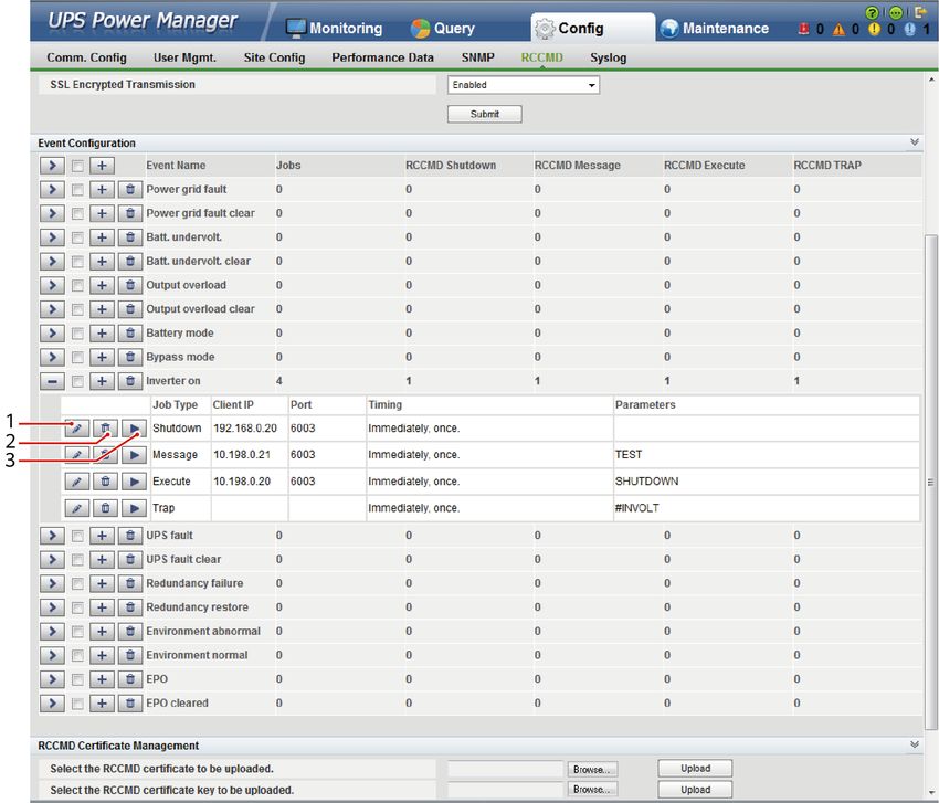
RMS-SNMP01A SNMP Card
User Manual                                                                      About This Document

                  Symbol                          Description

                                                  Indicates a hazard with a low level of risk which,
                                                  if not avoided, could result in minor or moderate
                                                  injury.

                                                  Indicates a potentially hazardous situation which,
                                                  if not avoided, could result in equipment damage,
                                                  data loss, performance deterioration, or
                                                  unanticipated results.
                                                  NOTICE is used to address practices not related to
                                                  personal injury.

                                                  Supplements the important information in the
                                                  main text.
                                                  NOTE is used to address information not related
                                                  to personal injury, equipment damage, and
                                                  environment deterioration.

Change History
                 Changes between document issues are cumulative. The latest document issue
                 contains all the changes made in earlier issues.

Issue 09 (2020-08-12)
                 Deleted the iBAT 2.0 feature.

Issue 08 (2020-01-09)
                 Deleted the Modbus-TCP feature.

Issue 07 (2019-12-20)
                 Updated the safety information.

Issue 06 (2019-11-26)
                 Updated the SNMP version description.

Issue 05 (2019-10-18)
                 Updated the GSM description.

Issue 04 (2017-01-19)
                 ●      Added the DHCP feature.
                 ●      Added the external dry contact card (RMS-RELAY02B) feature.

Issue 09 (2020-08-12)          Copyright © Huawei Technologies Co., Ltd.                               iii
RMS-SNMP01A SNMP Card
User Manual                                                                   About This Document

Issue 03 (2016-04-30)
                 The software version has been updated in the following aspects:
                 ●      Added the CIM feature.
                 ●      Added the RCCMD feature.

Issue 02 (2016-03-25)
                 ●      Added the following description: The UPS2000-G used with the SNMP card
                        does not support the GSM modem.
                 ●      Added the AI/DI module to the optional components.
                 ●      Updated the software.
                 ●      The document name changed to RMS-SNMP01A V100R002 SNMP Card User
                        Manual.

Issue 01 (2015-08-18)
                 This is the first release.

Issue 09 (2020-08-12)          Copyright © Huawei Technologies Co., Ltd.                         iv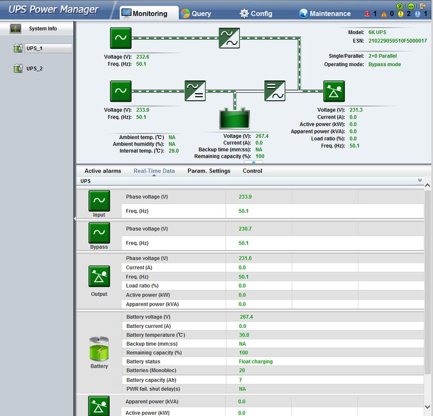
RMS-SNMP01A SNMP Card
User Manual                                                                                                                                                                         Contents

                                                                                                                                                              Contents

About This Document................................................................................................................ ii
1 Safety Information.................................................................................................................. 1
2 Overview....................................................................................................................................2
2.1 Functions.................................................................................................................................................................................... 2
2.2 Port Description....................................................................................................................................................................... 3

3 Installation and Basic Settings............................................................................................. 6
3.1 Preparations.............................................................................................................................................................................. 6
3.2 Precautions................................................................................................................................................................................ 6
3.3 Installing the SNMP Card..................................................................................................................................................... 7
3.4 Setting an IP Address for the SNMP Card...................................................................................................................... 8
3.5 Installing Optional Components......................................................................................................................................10
3.5.1 Temperature and Humidity Sensor............................................................................................................................. 10
3.5.2 AI/DI Module....................................................................................................................................................................... 11
3.5.3 GSM Modem....................................................................................................................................................................... 14
3.5.4 External Dry Contact Card.............................................................................................................................................. 15

4 Managing the UPS on the WebUI..................................................................................... 18
4.1 Introduction to Web Pages................................................................................................................................................ 18
4.2 Preparations for Login......................................................................................................................................................... 19
4.2.1 Installing an HTTPS Certificate for the Web Browser........................................................................................... 19
4.2.2 Setting Internet Explorer Options................................................................................................................................ 22
4.2.3 Privacy Statement............................................................................................................................................................. 24
4.3 WebUI Login........................................................................................................................................................................... 25
4.4 Monitoring Page....................................................................................................................................................................27
4.4.1 Monitoring and Active Alarms Page........................................................................................................................... 27
4.4.2 Real-Time Data Page........................................................................................................................................................ 28
4.4.3 Param. Settings Page....................................................................................................................................................... 29
4.4.4 Control Page........................................................................................................................................................................ 30
4.5 Query Page..............................................................................................................................................................................31
4.5.1 Logs........................................................................................................................................................................................ 31
4.5.2 Performance Data............................................................................................................................................................. 31
4.5.3 Historical Alarms............................................................................................................................................................... 32
4.6 Configuration Page.............................................................................................................................................................. 33

Issue 09 (2020-08-12)                                     Copyright © Huawei Technologies Co., Ltd.                                                                                               v
RMS-SNMP01A SNMP Card
User Manual                                                                                                                                                                      Contents

4.6.1 Comm. Config Page.......................................................................................................................................................... 33
4.6.2 User Mgmt. Page............................................................................................................................................................... 37
4.6.3 Site Config Page................................................................................................................................................................. 39
4.6.4 Performance Data Page.................................................................................................................................................. 41
4.6.5 SNMP..................................................................................................................................................................................... 41
4.6.6 RCCMD.................................................................................................................................................................................. 45
4.7 Maintenance Page................................................................................................................................................................ 54
4.7.1 Data Maintenance.............................................................................................................................................................54
4.7.2 Upgrade Page..................................................................................................................................................................... 55

5 Managing the UPS by Using the iManager NetEco 1000U......................................... 56
5.1 Introduction to the NetEco 1000U..................................................................................................................................56
5.2 Applying for Access Rights................................................................................................................................................. 56
5.3 Managing the UPS............................................................................................................................................................... 56

6 Managing the UPS by Using the NMS Complying with Huawei Standard............. 57
6.1 SNMP Card Versions............................................................................................................................................................ 57
6.2 Installing the UPS MIB Library......................................................................................................................................... 57
6.3 Managing the UPS by Using the NMS.......................................................................................................................... 57
6.3.1 Applying for Access Rights............................................................................................................................................. 57
6.3.2 Managing the UPS............................................................................................................................................................ 58

7 Managing the UPS by Using the NMS Complying with RFC1628 Standard............59
7.1 Installing the UPS MIB Library......................................................................................................................................... 59
7.2 Managing the UPS by Using the NMS.......................................................................................................................... 59
7.2.1 Applying for Access Rights............................................................................................................................................. 59
7.2.2 Managing the UPS............................................................................................................................................................ 60

8 Protecting the Server by Using NetShutdown............................................................... 61
8.1 Introduction to NetShutdown...........................................................................................................................................61
8.2 Adding NetShutdown Software to the SNMP Card.................................................................................................. 61
8.3 Obtaining the UPS Status.................................................................................................................................................. 61

9 Protecting the Server by Using the RCCMD Software..................................................62
9.1 Introduction to the Software............................................................................................................................................ 62
9.2 RCCMD Event Shutdown and Message Sending........................................................................................................62
9.3 UPS Alive Check Function.................................................................................................................................................. 63

10 Troubleshooting...................................................................................................................66
11 Upgrading the SNMP Card................................................................................................67
12 Changing the SSH Access Password............................................................................... 71
12.1 Maintenance Suggestions................................................................................................................................................71
12.2 Changing an Authentication Password....................................................................................................................... 72

A Acronyms and Abbreviations............................................................................................. 75

Issue 09 (2020-08-12)                                     Copyright © Huawei Technologies Co., Ltd.                                                                                           vi
RMS-SNMP01A SNMP Card
User Manual                                                                         1 Safety Information

                                                   1         Safety Information

                 1.     Wear electrostatic discharge (ESD) gloves when you install the SNMP card.
                 2.     Do not hot-swap the SNMP card that is connected to a temperature and
                        humidity sensor.
                 3.     Change the preset password in your first login to the SNMP card on the
                        WebUI. For details, see section 4.6.2 User Mgmt. Page.
                 4.     Change the preset password in your first login to the SNMP card over Secure
                        Shell (SSH). For details, see section 12.2 Changing an Authentication
                        Password.
                 5.     Exercise caution when manually shutting down the UPS inverter for
                        transferring to bypass mode, or when adjusting the UPS output voltage level
                        or frequency. Doing so may affect the power supply to equipment.
                 6.     Exercise caution when setting battery parameters. Incorrect settings will affect
                        the power supply and battery lifespan.

Issue 09 (2020-08-12)           Copyright © Huawei Technologies Co., Ltd.                              1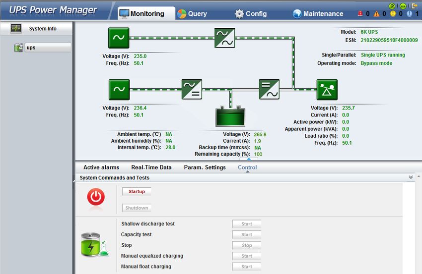
RMS-SNMP01A SNMP Card
User Manual                                                                                     2 Overview

                                                                          2          Overview

2.1 Functions
                 The SNMP card is an optional monitoring component of the UPS. It provides
                 SNMP agent and web management functions. The SNMP card allows users to
                 remotely manage the UPS by using a network management system (NMS),
                 Huawei NetEco, or a web browser on a computer network. A maximum of 16
                 SNMPv3 users and 80 NMS users can manage the UPS. Only 8 NMS users have
                 write permission. The WebUI supports a maximum of two concurrent online users.
                 The SNMP card has an exquisite, advanced, and unique design, and features high
                 performance and reliability. It has the following functions and features:
                 ●      Supports UPS2000-G-(6 kVA–20 kVA) and UPS2000-A-(6 kVA–10 kVA) series
                        and implements parallel system management using only one SNMP card.
                 ●      Adapts to the 10 Mbps/100 Mbps Ethernet, and supports Network Address
                        Translation (NAT).
                 ●      Supports SNMP, HTTPS, and SSH.
                 ●      Supports SNMP agent v1, v2c, and v3. The HUAWEI_UPS_MIB library or UPS-
                        RFC1628-MIB library can be downloaded from its own web page, instead of
                        any CD-ROM.
                 ●      Enables remote management on Windows or Linux using a web browser. The
                        supported web browsers include Internet Explorer 8, Internet Explorer 9,
                        Internet Explorer 10, Internet Explorer 11, and Firefox 33.1.
                 ●      Provides an access security mechanism, assigns rights to users based on roles,
                        and implements IP address control over HTTPS, SNMPv3, and SNMP access to
                        prevent unauthorized access.
                 ●      Provides comprehensive UPS management, such as producing an energy flow
                        diagram, displaying alarms, controlling UPS running, collecting performance
                        data statistics, as well as allowing users to view, retrieve, and export historical
                        alarms and operation logs.
                 ●      Supports optional components such as temperature and humidity modules,
                        AI/DI Module, and external dry contact card.
                 ●      Supports connecting a USB GSM modem to monitor UPS working status and
                        receive/send fault and alarm short messages.

Issue 09 (2020-08-12)           Copyright © Huawei Technologies Co., Ltd.                                 2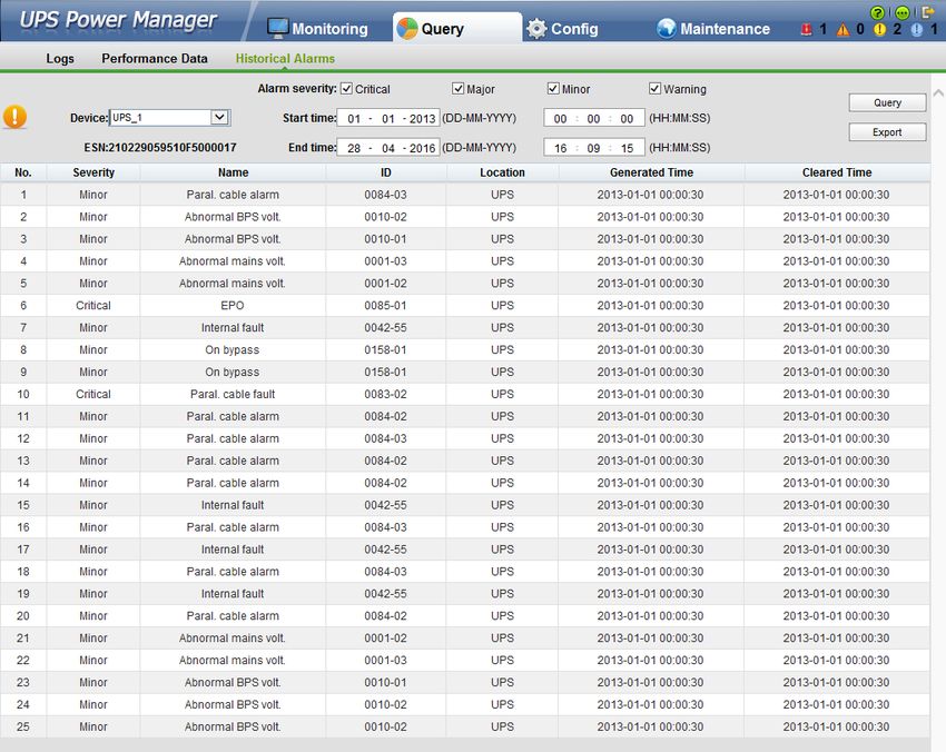
RMS-SNMP01A SNMP Card
User Manual                                                                                            2 Overview

                 ●      Works with NetShutdown, a computer and server security shutdown program
                        developed by Huawei, to automatically shut down the computers and servers
                        where NetShutdown is installed to protect customer data and reduce loss.
                 ●      Works with RCCMD, a client shutdown software developed by Generex, to
                        automatically and safely shut down the client that is installed with the
                        RCCMD, thereby protecting customers' data and preventing loss.
                 ●      Alarm information is sent to the specified user mailbox at the specified time.
                         NOTE

                        Change the preset password in your first login to the SNMP card. For details of WebUI, see
                        section 4.6.2 User Mgmt. Page. For details of SSH, see section 12.2 Changing an
                        Authentication Password.

2.2 Port Description
                 Figure 2-1 shows the ports on the SNMP card.

                 Figure 2-1 Ports

                  (1) Port for southbound device                    (2) USB port (GSM modem supported)
                  (3) RS485 southbound interface                    (4) Ethernet port

                 The NETWORK port of SNMP card is an RJ45 port. It communicates with the 10
                 Mbps/100 Mbps Ethernet over a standard network cable. The indicators show the
                 communication status. Table 2-1 describes the ports and indicators.

                 Table 2-1 Description of ports and indicators

                  Silk Screen               Name                    Indicator               Description

                  TEM_HUM                   Port for                N/A                     This port connects
                                            southbound                                      to temperature
                                            device                                          and humidity
                                                                                            sensor or external
                                                                                            dry contact card.

Issue 09 (2020-08-12)            Copyright © Huawei Technologies Co., Ltd.                                           3
RMS-SNMP01A SNMP Card
User Manual 2 Overview
Silk Screen Name Indicator Description
USB USB port N/A This port connects
to GSM modem.
COM RS485 N/A This port connects
southbound to AI/DI module.
interface
NETWORK Ethernet port Green indicator Off: No network
cable is
connected.
Steady on: A
network cable is
connected.
Yellow indicator Blinking: The card
is communicating
with the network.
NOTE
● The NETWORK port is protected by a security mechanism.
● The COM port and TEM_HUM port use Modbus protocol, without reference to the
access authentication mechanism.
● The USB port connects to the GSM modem, without reference to the system
management.
The SNMP card is equipped with a temperature and humidity sensor or an
external dry contact card over an RS485 bus. Table 2-2 lists the port definition.
Table 2-2 TEM_HUM port
Port Pin No. Signal Port Type
J3004 1 GND RJ11
2 N/A
3 RS485–
4 RS485+
5 N/A
6 12V_OUT
The COM port on the SNMP card is an RS485 southbound interface, connecting
AI/DI module. Table 2-3 describes the pin definitions of the port.
Issue 09 (2020-08-12) Copyright © Huawei Technologies Co., Ltd. 4RMS-SNMP01A SNMP Card
User Manual 2 Overview
Table 2-3 COM port
Port Pin No. Signal Port Type
J3011 1 RS485+ RJ45
2 RS485–
3 N/A
4 RS485+
5 RS485–
6 N/A
7 N/A
8 N/A
Issue 09 (2020-08-12) Copyright © Huawei Technologies Co., Ltd. 5RMS-SNMP01A SNMP Card
User Manual 3 Installation and Basic Settings
3 Installation and Basic Settings
3.1 Preparations
Before installing the SNMP card, prepare materials and tools listed in Table 3-1.
Table 3-1 Materials and tools
Appearance, Specifications, and Name
SNMP card Network cable Phillips Electrostatic
(RJ45 connectors screwdriver discharge (ESD)
on both ends) gloves
3.2 Precautions
● The SNMP card supports hot swap, when it is not equipped with a
temperature and humidity sensor. The SNMP card does not support hot swap,
when it is equipped with a temperature and humidity sensor.
● Some electronic components in the SNMP card are sensitive to ESD. Do not
use your hands or electrical objects to touch electronic components or circuits
in the SNMP card, preventing ESD from damaging the SNMP card. Hold the
edges of the SNMP card when you move or install it.
● Wear ESD gloves when you install the SNMP card.
Issue 09 (2020-08-12) Copyright © Huawei Technologies Co., Ltd. 6RMS-SNMP01A SNMP Card
User Manual 3 Installation and Basic Settings
3.3 Installing the SNMP Card
The methods for installing SNMP cards are the same on different UPSs of Huawei.
The SNMP card is installed in the optional card slot INTELLISLOT at the rear panel
of the UPS.
Procedure
Step 1 Remove the cover of the optional card slot on the real panel of the UPS, as shown
in Figure 3-1.
Figure 3-1 Removing the cover of the optional card slot
NOTE
Store the cover well for future use.
Step 2 Insert the SNMP card into the slot and tighten screws, as shown in Figure 3-2.
Issue 09 (2020-08-12) Copyright © Huawei Technologies Co., Ltd. 7RMS-SNMP01A SNMP Card
User Manual 3 Installation and Basic Settings
Figure 3-2 Inserting the SNMP card into the slot
NOTE
The optional card uses M3 screws. The recommended torque is 0.5 N·m.
Step 3 (Optional) If there is a temperature and humidity sensor, connect it to the
TEM_HUM port on the SNMP card. For the method about how to connect the
other end of the cable, see the user manual related to the temperature and
humidity sensor.
Step 4 Connect one end of the network cable to the NETWORK port on the SNMP card
and the other end to an Ethernet port. If the green indicator turns on and the
yellow indicator blinks, the SNMP card is successfully installed and is properly
communicating with the Ethernet.
----End
3.4 Setting an IP Address for the SNMP Card
The factory settings are as follows:
● IP address: 192.168.0.10
● Sub mask: 255.255.255.0
● Gateway: 192.168.0.1
NOTE
The preceding are the default values of IP address, Sub mask, and Gateway. Modify
the settings based on the network segment that the UPS belongs to.
After the SNMP card is installed, you can set the SNMP card IP address on the LCD
of the UPS2000-G. The LCD of the UPS2000-A does not support settings of
Issue 09 (2020-08-12) Copyright © Huawei Technologies Co., Ltd. 8RMS-SNMP01A SNMP Card
User Manual 3 Installation and Basic Settings
monitoring parameters for the SNMP card. Set the parameters on the WebUI. For
details, see 4.6.1 Comm. Config Page.
Procedure
Step 1 Press on the LCD. On the Main Menu, choose Settings.
Step 2 Enter a password. (The preset password is 000001.)
Step 3 Select Communication Card.
Step 4 Press . The Communication Card screen is displayed.
Step 5 On the Communication Card screen, set an IP address, Sub mask, and Gateway
for the SNMP card.
----End
Issue 09 (2020-08-12) Copyright © Huawei Technologies Co., Ltd. 9RMS-SNMP01A SNMP Card
User Manual 3 Installation and Basic Settings
3.5 Installing Optional Components
3.5.1 Temperature and Humidity Sensor
Temperature and Humidity Sensor Types
The SNMP card supports temperature and humidity sensor. The model of the
temperature and humidity sensor is ENR1DETA MODULE.
NOTE
● If the SNMP card is equipped with a temperature and humidity sensor, you can view the
UPS temperature and humidity on the Monitoring page, as shown in Figure 4-9. If the
SNMP card is not equipped with a temperature and humidity sensor, NA is displayed.
● According to the temperature and humidity sensor document, set the temperature and
humidity sensor address to 1 (toggle switch 1 is ON and other toggle switches are OFF
for ENR1DETA MODULE, as shown in Figure 3-3) and baud rate to 9600.
Figure 3-3 DIP switch on the ambient temperature and humidity sensor
RJ11 Terminal
The temperature and humidity sensor connects to an SNMP card over a symmetric
twisted pair. If the sensor model is ENR1DETA MODULE, both ends of the twisted
pair are RJ11 terminals.
Insert the one end (RJ11 terminal) of the temperature and humidity sensor cable
to the TEM_HUM port on the SNMP card, and the other end to the temperature
and humidity sensor. For the method about how to connect the other end of the
cable, see the user manual related to the temperature and humidity sensor. Figure
3-4 shows the RJ11 terminal.
Issue 09 (2020-08-12) Copyright © Huawei Technologies Co., Ltd. 10RMS-SNMP01A SNMP Card
User Manual 3 Installation and Basic Settings
Figure 3-4 RJ11 terminal
Figure 3-4 shows the pin sequence in the RJ11 terminal. In view A, the pins in the
RJ11 terminal are numbered 1 to 6 (X1.1 to X1.6) from bottom up. Table 3-2 lists
the signals corresponding to each pin in the RJ11 terminal.
Table 3-2 Mapping between wiring terminals and signals
RJ11 Terminal to the RJ11 Terminal Signal ENR1DETA MODULE
SNMP Card RJ11 Terminal Signal
X1.1 GND GND
X1.2 N/A N/A
X1.3 RS485– RS485–
X1.4 RS485+ RS485+
X1.5 N/A N/A
X1.6 12 V 12 V
3.5.2 AI/DI Module
NOTICE
AI/DI_1 is a 12 V level output port that cannot connect to an external power
source.
AI/DI Module Types
The SNMP card supports only one AI/DI module, and its model is MUE06A. If the
SNMP card is configured with the AI/DI module, it can support one AI/DI signal
port. This port provides 12 V DC outputs for sensors and offers internal
Issue 09 (2020-08-12) Copyright © Huawei Technologies Co., Ltd. 11RMS-SNMP01A SNMP Card
User Manual 3 Installation and Basic Settings
overcurrent protection. For details about other functions and the methods of using
these functions, see the ECC500 V600R001C03 User Manual.
NOTE
● Set the address of the AI/DI module to 3 (toggle switches 1 to 3 are used to set the
address of the AI/DI module, and toggle switch 4 is used to enable or disable the
resistance for the RS485 interface). Toggle switches 1 and 2 are set to ON and toggle
switch 3 is set to OFF, as shown in Figure 3-5.
● COM_IN port is for communication. The baud rate is 9600.
● Electrical level is output from the AI/DI_1 port. Pin 3 of the AI/DI_1 port is DC 12 V, 54
mA, and pin 8 of the AI/DI_1 port is GND, as shown in Figure 3-5.
● When the signal is unstable due to signal reflection which is caused by the long
communication route (greater than 200 m), set toggle switch 4 to ON for the farthest
AI/DI module, as shown in Figure 3-5. After the DIP switch settings are modified, power
off and restart the AI/DI module for the new settings to take effect.
● The AI/DI_1 port can connect to the UPS run indicator. Table 3-3 shows the indicator
status.
Figure 3-5 AI/DI module
(1) Port for the SNMP (2) Port for DC 12 V (3) DC 15 V power input
card power (adapter required)
(4) DIP switch (5) Cascading port
Table 3-3 Status of UPS run indicator connected to the AI/DI_1 port
Single UPS/ UPS Working AI/DI_1 Port UPS Run
Parallel System Modes Output Voltage Indicator Status
Single UPS Bypass mode or 12 V On
no power supply
mode
Single UPS Normal mode, 0V Off
battery mode,
mains ECO mode,
or battery ECO
mode
Issue 09 (2020-08-12) Copyright © Huawei Technologies Co., Ltd. 12RMS-SNMP01A SNMP Card
User Manual 3 Installation and Basic Settings
Single UPS/ UPS Working AI/DI_1 Port UPS Run
Parallel System Modes Output Voltage Indicator Status
Parallel system All UPSs work in 0V Off
normal mode,
battery mode,
mains ECO mode,
or battery ECO
mode.
Parallel system One UPS works in 12 V On
bypass mode or
no power supply
mode.
RJ45 Terminal
When the AI/DI module is connected to the SNMP card, both terminals are RJ45
terminals.
Insert one end (RJ45 terminal) into the COM port on the SNMP card, and the
other end into the COM_IN port on the AI/DI module. Figure 3-6 shows the RJ45
terminals.
Figure 3-6 RJ45 terminals
As shown by View A in Figure 3-6, the pins are X1.1 to X1.8 from left to right.
Table 3-4 describes the mapping between wiring terminals.
Table 3-4 Mapping between wiring terminals
Connecting to SNMP Card Connecting to AI/DI Module
(RJ45) Terminal RJ45 Terminal RJ45 Terminal (RJ45) Terminal
Connecting to Signal on the Signal on the Connecting to
SNMP Card SNMP Card AI/DI Module AI/DI Module
X1.1 RS485+ RS485_T+ X2.1
X1.2 RS485– RS485_T– X2.2
X1.3 N/A N/A X2.3
X1.4 RS485+ RS485_R+ X2.4
Issue 09 (2020-08-12) Copyright © Huawei Technologies Co., Ltd. 13RMS-SNMP01A SNMP Card
User Manual 3 Installation and Basic Settings
Connecting to SNMP Card Connecting to AI/DI Module
X1.5 RS485– RS485_R– X2.5
X1.6 N/A N/A X2.6
X1.7 N/A N/A X2.7
X1.8 N/A N/A X2.8
3.5.3 GSM Modem
A GSM modem provided by Huawei can be configured for the SNMP card. The
GSM modem model needs to be determined based on the actual situation. Figure
3-7 shows the GSM modem appearance.
NOTE
● The device that needs to receive short messages from the GSM modem must support
short messages in the 3GPP TS 23.038 8-bit format.
● The UPS2000-G used with the SNMP card does not support the GSM modem.
● If a GSM modem is configured for the SNMP card, and a SIM card is inserted properly,
users can view the SMS module status (indicating that the SMS module is present) in
the communication status bar of the WebUI, as shown in Figure 4-9. If a GSM modem
is not configured, the status indicates that the SMS module is not present.
● Only the SMS function of the GSM modem is used. This function enables information
such as UPS fault alarms to be sent and received by short message. For details, see the
alarm notification configuration in section 4.6.1 Comm. Config Page. For details about
other functions of the GSM modem and the methods for using these functions, see
related manuals delivered with the GSM modem.
Issue 09 (2020-08-12) Copyright © Huawei Technologies Co., Ltd. 14RMS-SNMP01A SNMP Card
User Manual 3 Installation and Basic Settings
Figure 3-7 GSM modem appearance
3.5.4 External Dry Contact Card
An external dry contact card can be configured for the SNMP card. You are
advised to configure an external dry contact card of the model RMS-RELAY02B.
Issue 09 (2020-08-12) Copyright © Huawei Technologies Co., Ltd. 15RMS-SNMP01A SNMP Card
User Manual 3 Installation and Basic Settings
Figure 3-8 External dry contact card
(1) External dry contact (2) RUN indicator (3) ALM indicator
card
(4) RS485_IN port (5) RS485_OUT port (6) Dry contact
(7) Reset button (8) Dual in-line package (9) Fastener
(DIP) switch
The external dry contact card connects to the UPS over an SNMP card. Figure 3-9
shows how to connect cables to the external dry contact card.
NOTICE
The RMS-SNMP01A card does not support connection to a temperature and
humidity sensor and an external dry contact card at the same time.
Issue 09 (2020-08-12) Copyright © Huawei Technologies Co., Ltd. 16RMS-SNMP01A SNMP Card
User Manual 3 Installation and Basic Settings
Figure 3-9 Connecting cables to the external dry contact card
NOTE
Refer to the external dry contact card user manual and set the card address to 8. Figure
3-10 shows the DIP switch status of the RMS-RELAY02B. 1 is set to ON and other toggle
switches are set to OFF. The baud rate is set to 9600.
Figure 3-10 DIP switch
Issue 09 (2020-08-12) Copyright © Huawei Technologies Co., Ltd. 17RMS-SNMP01A SNMP Card
User Manual 4 Managing the UPS on the WebUI
4 Managing the UPS on the WebUI
4.1 Introduction to Web Pages
NOTICE
User interfaces displayed in this document correspond to the version UPS2000
V200R001C91B082 and are for reference only.
● Monitoring page
– The Active Alarms page displays active alarms generated for the UPS.
– The Real-Time Data page displays real-time running data of UPS
modules.
– The Param. Settings page allows you to set the UPS temperature and
humidity alarm parameters.
– The Control page allows you to start or shut down the UPS.
● Query page
– The Logs page allows you to query users' operation information to know
recent operations.
– The Performance Data page displays the performance data of each UPS.
You can query and export the performance data of a selected UPS.
– The Historical Alarms page displays alarms of each UPS. You can query
and export the historical alarms of the selected UPS.
● Config page
– The Comm. Config page allows you to configure the IP address of SNMP
card, NAT mapping, Sender's Email Settings, Alarm Notification, RMS-
RELAY02B Settings.
– The User Mgmt page allows you to create, change, and delete users.
– The Site Config page allows you to set the system parameters, change
the system date and time, select a time zone, synchronize the local clock,
and import the SSL certificate.
Issue 09 (2020-08-12) Copyright © Huawei Technologies Co., Ltd. 18RMS-SNMP01A SNMP Card
User Manual 4 Managing the UPS on the WebUI
– The Performance Data page allows you to set the performance data
save period.
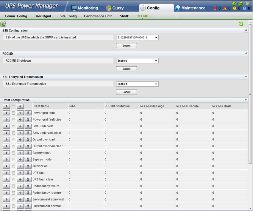
– The SNMP page allows you to change the SNMP version, add an NMS,
and configure the SNMP TRAP.
– The RCCMD page allows you to configure the ESN, shut down RCCMD,
perform SSL encrypted transmission, configure events, and manage the
RCCMD certificate.
● Maintenance page
– The Data Maintenance page allows you to export the users' operation
records, export the performance data, historical alarms, and serviceability
data of a single UPS or all UPSs over WebUI, and delete the performance
data and historical alarms of a single UPS or all UPSs.
– The Upgrade page allows you to upgrade the SNMP card software. For
the UPS2000-A, you can also upgrade the UPS software.
4.2 Preparations for Login
4.2.1 Installing an HTTPS Certificate for the Web Browser
Open the web browser (Internet Explorer 8 as an example). In the address box,
enter the SNMP card IP address to open the login page. If the SNMP card IP
address is not changed, enter https://192.168.0.10. When you access a web server
over Hypertext Transfer Protocol Secure (HTTPS), a security warning is displayed,
as shown in Figure 4-1.
Figure 4-1 Security warning
After you select Continue to this website (not recommended) in Figure 4-1,
click Certificate Error in the upper right corner. A dialog box is displayed, as
shown in Figure 4-2.
Issue 09 (2020-08-12) Copyright © Huawei Technologies Co., Ltd. 19RMS-SNMP01A SNMP Card
User Manual 4 Managing the UPS on the WebUI
Figure 4-2 Certificate Invalid dialog box
Click View Certificates in Figure 4-2. The dialog box providing the Certificate is
displayed, as shown in Figure 4-3.
Figure 4-3 Certificate dialog box
You can identify the cause of the following certificate error messages according to
Figure 4-3.
Issue 09 (2020-08-12) Copyright © Huawei Technologies Co., Ltd. 20RMS-SNMP01A SNMP Card
User Manual 4 Managing the UPS on the WebUI
● The security certificate presented by this website was not issued by a
certificate authority.
● The security certificate presented by this website has expired or is not yet
valid.
● The security certificate presented by this website was issued for a different
website's address.
The solutions are as follows:
1. The following are two methods to address the "The security certificate
presented by this website was not issued by a certificate authority" problem:
– Method 1: The user purchases a digital certificate from the known CA
vendor provided by Windows as the web server security certificate.
– Method 2: Install the root certificate for the digital certificate of the web
server in the Trusted Root Certification Authorities folder on the
Windows computer. The installation procedure is as follows:
Click Install Certificate, as shown in Figure 4-3. Choose Place all certificates
in the following store, and install the certificate in the Trusted Root
Certification Authorities folder, as shown in Figure 4-4.
Figure 4-4 Install Certificate dialog box
2. The following are two methods to address the "The security certificate
presented by this website has expired or is not yet valid" problem:
– Method 1: If the certificate is issued by a CA authority, choose Continue
to this website (not recommended). The WebUI runs properly, with no
connection interrupted.
– Method 2: Apply for a digital certificate again.
Issue 09 (2020-08-12) Copyright © Huawei Technologies Co., Ltd. 21RMS-SNMP01A SNMP Card
User Manual 4 Managing the UPS on the WebUI
3. The following are two methods to address the "The security certificate
presented by this website was issued for a different website's address"
problem:
– Method 1: In Internet Explorer, choose Internet Options > Advanced.
Deselect Warn about certificate address mismatch*, as shown in Figure
4-5.
– Method 2: Apply for a digital certificate again.
Figure 4-5 Setting Internet options
4.2.2 Setting Internet Explorer Options
Choose Internet Options > Advanced and set options, as shown in Figure 4-6.
Issue 09 (2020-08-12) Copyright © Huawei Technologies Co., Ltd. 22RMS-SNMP01A SNMP Card
User Manual 4 Managing the UPS on the WebUI
Figure 4-6 Setting Internet options
NOTE
● If Use TLS 1.2 is selected in Internet Explorer 8 or Internet Explorer 9, web pages cannot
be accessed.
● If Internet Explorer 10 or Internet Explorer 11 needs to be used to access web pages, you
must add the compatibility view settings. Choose Page > Compatibility View Settings
and add the SNMP card IP address. If the SNMP card IP address is not changed, add
192.168.0.10, as shown in Figure 4-7.
Issue 09 (2020-08-12) Copyright © Huawei Technologies Co., Ltd. 23RMS-SNMP01A SNMP Card
User Manual 4 Managing the UPS on the WebUI
Figure 4-7 Adding compatibility view settings
4.2.3 Privacy Statement
NOTICE
● Before performing any maintenance or change operations, Huawei engineers
must obtain the formal written authorization from the customer, and must
perform operations in compliance with local laws and regulations.
● If data required for fault locating needs to be transmitted out of the carrier's
network, engineers must obtain official approval from the customer, anonymize
the user information in accordance with national or local legal requirements,
and delete recorded files after the fault locating is complete.
The UPS2000 system logs, email sending, and GSM modem function may involve
system or personal information.
● Log
To facilitate fault location, the UPS2000 system may record the following
information in logs: detailed data exchange and processing procedures and
related system and personal user information, including the user account, IP
address, email address, mobile number, software version, device information,
and location.
Issue 09 (2020-08-12) Copyright © Huawei Technologies Co., Ltd. 24RMS-SNMP01A SNMP Card
User Manual 4 Managing the UPS on the WebUI
The system anonymizes personal data or displays part of the involved
personal data, such as displaying the email address usertest@huawei.com as
us*****t@huawei.com.
● Email
The UPS2000 can send alarm notification emails. When an alarm is generated
or cleared, the system sends an alarm email to the user. This function may
involve system and personal information, including the email address and
email password.
On the WebUI, only part of the email address is displayed. For example,
support@huawei.com is displayed as su****t@huawei.com. The email password
is displayed as ciphertext *****.
The system provides the personal data encryption protection. The email
address and password are encrypted using a secure encryption algorithm with
a cipher key.
The email sending function is disabled by default. Users need to configure the
email server address and enable this function.
● Mobile number
The UPS2000 can send alarm notification short messages through GSM
modem. When an alarm is generated or cleared, the system sends a short
message to users. Users can send short messages to query the system status
and active alarms. This function may involve system and personal
information, including the device information and mobile number.
The system displays part of a mobile number. For example, the system
displays 01415478578 as 014****8578 on the WebUI.
The system provides the personal data encryption protection. Mobile numbers
are encrypted using a secure encryption algorithm with a cipher key.
The GSM modem is an optional function and is disabled by default. Users
need to decide whether to buy it.
When using the preceding functions, you are obligated to take considerable
measures, in compliance with the laws of the countries concerned and the user
privacy policies of your company, to ensure that the personal data of users is fully
protected. For example, you need to anonymize user personal information and
delete source files in time.
4.3 WebUI Login
Procedure
Step 1 If the SNMP card IP address is not changed, enter https://192.168.0.10. Open the
web browser (Internet Explorer 8 as an example). In the address box, enter the
SNMP card IP address to open the login page, as shown in Figure 4-8
Issue 09 (2020-08-12) Copyright © Huawei Technologies Co., Ltd. 25RMS-SNMP01A SNMP Card
User Manual 4 Managing the UPS on the WebUI
Figure 4-8 Login page
Step 2 Set the language, user name, password, and verify code. The default user name is
admin, and the preset password is Changeme. Table 4-1 describes UPS users.
Table 4-1 Description of UPS users
User Name Password User Rights
admin Changeme Performs all operations on the WebUI,
including:
● System running information browsing
● Parameter configuration
● System control (startup, shutdown)
● System configuration(communication
configuration, user management, site
configuration, performance data, SNMP,
and RCCMD)
● System maintenance (upgrade, operation
record maintenance, performance data
maintenance, historical alarms
maintenance, serviceable data
maintenance)
guest N/A Only browses system running information,
without permission to perform any system
changes.
NOTE
● There is no verification code on the login page by default. After three login failures, a
verification code is required.
● If you enter incorrect passwords for five consecutive times, your account is locked for 1
hour.
Step 3 Click Login. The Monitoring page is displayed, as shown in Figure 4-9.
----End
Issue 09 (2020-08-12) Copyright © Huawei Technologies Co., Ltd. 26RMS-SNMP01A SNMP Card
User Manual 4 Managing the UPS on the WebUI
4.4 Monitoring Page
4.4.1 Monitoring and Active Alarms Page
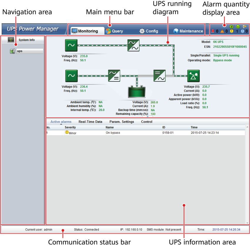
After login, the Monitoring page is displayed, showing the UPS model and ESN.
The UPS information area presents Active Alarms, as shown in Figure 4-9. Click
the device name on the upper left corner to edit it, or edit it by pressing Enter.
Figure 4-9 Monitoring page
Table 4-2 Description of the Monitoring page
Area Function
Navigation area Lists the monitored UPSs.
Issue 09 (2020-08-12) Copyright © Huawei Technologies Co., Ltd. 27RMS-SNMP01A SNMP Card
User Manual 4 Managing the UPS on the WebUI
Area Function
Main menu bar Displays the main menus: Monitoring,
Query, Config, and Maintenance.
Alarm quantity display area Displays the number of active alarms,
including critical alarms, major alarms
minor alarms, and warning.
UPS running diagram Shows the UPS running information,
including input and output
parameters, battery parameters, power
flow, environment parameters, and
working mode.
UPS information area Provides four pages: Active Alarms,
Real-Time Data, Param. Settings, and
Control.
Communication status bar Displays the current user name,
Ethernet connection status, IP address
of the SNMP card, time, and SMS
module status.
4.4.2 Real-Time Data Page
In the UPS information area, click Real-Time Data > UPS, you can view the UPS
running data on the Real-Time Data page. The data includes the input voltage
and frequency, bypass voltage and frequency, output voltage, current, frequency,
load ratio, power, battery voltage, current, temperature, and backup time. Figure
4-10 is shown in the UPS running diagram.
Issue 09 (2020-08-12) Copyright © Huawei Technologies Co., Ltd. 28RMS-SNMP01A SNMP Card
User Manual 4 Managing the UPS on the WebUI
Figure 4-10 Real-time data (UPS)
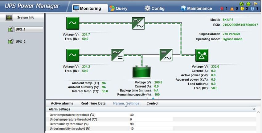
4.4.3 Param. Settings Page
In the UPS information area, choose Param. Settings > Alarm Settings, you can
set the high and low temperature and humidity alarm thresholds, as shown in
Figure 4-11. If you click a text box, the value range is displayed. Enter a value
within the range. Table 4-3 lists the default values and value ranges.
NOTE
The Param. Settings is active only the SNMP card is equipped with a temperature and
humidity sensor.
Issue 09 (2020-08-12) Copyright © Huawei Technologies Co., Ltd. 29RMS-SNMP01A SNMP Card
User Manual 4 Managing the UPS on the WebUI
Figure 4-11 Parameter settings (alarm settings)
Table 4-3 Default parameter values and value ranges
Parameter Default Value Value Range
Overtemperature 40°C 30–60°C
threshold
Undertemperature 0°C –30ºC to +10°C
threshold
Overhumidity threshold 90% RH 70–100% RH
Underhumidity threshold 10% RH 0–40% RH
4.4.4 Control Page
In the UPS information area, choose Control > System Commands and Tests, and
you can start or shut down the UPS, as shown in Figure 4-12.
Issue 09 (2020-08-12) Copyright © Huawei Technologies Co., Ltd. 30RMS-SNMP01A SNMP Card
User Manual 4 Managing the UPS on the WebUI
Figure 4-12 Control page
4.5 Query Page
4.5.1 Logs
The Logs page provides user operation information, as shown in Figure 4-13. It
lists a maximum of 1000 records.
Figure 4-13 Logs page
4.5.2 Performance Data
The Performance Data page records UPS working performance data, including
the input (voltage and frequency) and output (voltage, current, frequency, and
load ratio) information. Select Performance Data in the Query at the first menu
level to enter the performance statistics page, as shown in Figure 4-14.
Issue 09 (2020-08-12) Copyright © Huawei Technologies Co., Ltd. 31RMS-SNMP01A SNMP Card
User Manual 4 Managing the UPS on the WebUI
Figure 4-14 Performance Data page
Select the device, set the start time, end time, and click Query. The page then
displays the performance data in the specified time period for the selected UPS.
The time interval is configured in Config> Performance Data. The fault value is
30s, as shown in Figure 4-15.
Figure 4-15 Performance Data Query page
4.5.3 Historical Alarms
Select Historical Alarms from the menu at the first level. Then you can query
historical alarms in a specified time period, as shown in Figure 4-16.
Issue 09 (2020-08-12) Copyright © Huawei Technologies Co., Ltd. 32RMS-SNMP01A SNMP Card
User Manual 4 Managing the UPS on the WebUI
Figure 4-16 Historical Alarms page
Select an alarm severity (critical, major, minor, or warning), select the device, set
the start time and end time, and click Query. The page displays historical alarms
in the specified time period for the selected UPS, as shown in Figure 4-17.
Figure 4-17 Historical Alarms Query page
4.6 Configuration Page
4.6.1 Comm. Config Page
On the main menu bar, click Config. The Comm. Config page is displayed by
default, as shown in Figure 4-18. You can also click User Mgmt., Site Config,
Performance Data, SNMP, and RCCMD.
Issue 09 (2020-08-12) Copyright © Huawei Technologies Co., Ltd. 33RMS-SNMP01A SNMP Card
User Manual 4 Managing the UPS on the WebUI
The Comm. Config page allows you to change the system IP settings, and
configure a sender's email, and configure an alarm notification, perform RMS-
RELAY02B settings.
Changing the IP Address of the SNMP Card
Under System IP Settings, change the SNMP card IP address and click Submit, as
shown in Figure 4-18. Log in to the WebUI with the new IP address.
NOTICE
If the UPS monitor does not support the DHCP function, after the DHCP is
selected for the SNMP card, you cannot set the IP address of the SNMP card on
the UPS monitor. You are advised to update the version of the UPS monitor.
On the WebUI, the MAC address of the SNMP card is displayed. You can select
DHCP and click Submit to apply for a dynamic IP address to the DHCP server.
After that, log in to the WebUI using the newly applied IP address. If you select
When the IP address is automatically assigned, send an email., the SNMP card
will send an email to you to notify the IP address change.
NOTE
● You are advised to select When the IP address is automatically assigned, send an
email.
● If DHCP fails to be allocated, the IP address of the SNMP card will restore to the default
IP address 192.168.0.10 and the DHCP will be deselected.
● If DHCP is selected and the IP address expires during SNMP card power-off, the IP
address will be reallocated after the SNMP card starts.
● If DHCP is selected and DHCP fails to be allocated after the SNMP card restarts, the IP
address of the SNMP card will restore to the default IP address 192.168.0.10.
The NAT uses a few public IP addresses to represent a large number of private IP
addresses so that the SNMP card in the internal network can be accessed through
the external network. This function is disabled by default. If this function is
enabled, you can access the SNMP card in the internal network through the
external network by using a router with the NAT function.
Issue 09 (2020-08-12) Copyright © Huawei Technologies Co., Ltd. 34RMS-SNMP01A SNMP Card
User Manual 4 Managing the UPS on the WebUI
Figure 4-18 Comm. Config page
Configuring a Sender's Email Settings
Under the Sender's Email Settings, set Email server IP address, Sender's email,
SMTP port, and Use secure connection (TLS encryption). Choose if User
account authentication required when sending a mail, if you select Yes, set the
User Name and Password. Then click Submit. When an alarm is generated, the
alarm information will be sent to the receivers' mailboxes. You can delete the
sender's email configurations, after click Delet.
Configuring Alarm Notification Settings
On the Alarm Notification Settings page, you can choose whether to enable
email and SMS notifications (requiring a GSM modem), Timely Reminder, and
select alarm severities (critical, major, minor, or All), as shown in Figure 4-18. The
user name and SMS notification receiver number can be configured on the User
Mgmt. tab.
If you enable alarm notification by email or SMS, when there is an alarm, the
system will send emails or short messages to the receiver at 8:00, 12:00, 16:00,
and 20:00. If the SNMP card is powered on within one hour after 8:00, 12:00,
16:00, or 20:00, the system will check whether the alarm notification has been
sent at the previous hour after power-on. If the notification has not been sent, the
system will send it. If the notification has been sent, the system will not send
again. If the SNMP card is powered on more than one hour after 8:00, 12:00,
Issue 09 (2020-08-12) Copyright © Huawei Technologies Co., Ltd. 35RMS-SNMP01A SNMP Card
User Manual 4 Managing the UPS on the WebUI
16:00, or 20:00, the alarm notification will not be sent, and it will be sent at the
next specified hour.
NOTE
● The alarm content includes the alarm device, alarm severity, alarm ID, alarm cause ID,
alarm name, generation time, and clearance time.
● Alarm sending example: If the SNMP card is powered on between 8:00 and 8:59, the
SNMP card will check whether the alarm notification has been sent at 8:00. If it has
been sent, the SNMP card will not send again. If it has not been sent, the SNMP card
will send it. If the SNMP card is powered on between 9:00 and 11:59, the alarm
notification will not be sent. It will be sent at 12:00.
RMS-RELAY02B Configurations
RMS-RELAY02B configurations are used to associate the DI/DO status of the
external dry contact card and UPS status. You can disable the functions of the
external dry contact card by disabling RMS-RELAY02B input. The SNMP card
changes the DO output status by setting the DO type and associated event. The
SNMP card controls UPS startup/shutdown based on the configured DI type and
DI input status.
● For DO1 to DO4:
The NO and COM pins of DO are closed, and the NC and COM pins of DO are
open, when the associated event is consistent with the UPS status; otherwise,
the NC and COM pins of DO are closed, and the NO and COM pins of DO are
open.
● For DI1 and DI2:
If Type is set to NO, the UPS executes the configured associated event when
DI has a 12–24 V DC input; otherwise, the UPS does not execute the
associated event. If Type is set to NC, the UPS does not execute the
configured associated event when DI has a 12–24 V DC input; otherwise, the
UPS executes the associated event.
NOTE
The UPS performs the shutdown command if Type is set to NO, DI1 is set to Startup, DI2
is set to Shutdown, and there is a 12–24 V DC input. If the UPS is faulty, it does not
perform the startup command when DI is set to Startup. Rectify the UPS fault first.
Figure 4-19 RMS-RELAY02B Settings
Issue 09 (2020-08-12) Copyright © Huawei Technologies Co., Ltd. 36You can also read