RS9116W BT Classic AT Command Programming Reference Manual - Version 2.4 June 28, 2021
←
→
Page content transcription
If your browser does not render page correctly, please read the page content below

RS9116W BT Classic AT Command Programming
              Reference Manual
                                                 Version 2.4
                                                June 28, 2021

silabs.com | Building a more connected world.                   1 | Page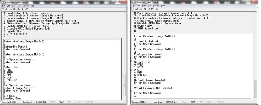
RS9116W BT Classic AT Command Programming Reference Manual
                                                                                                                                         Version 2.4

Table of Contents
1    Overview .................................................................................................................................................................... 5
2    Bootloader ................................................................................................................................................................. 8
3    Host Interfaces ........................................................................................................................................................ 20
     3.1 UART Interface ............................................................................................................................................... 20
4    Classic Command Mode Selection ....................................................................................................................... 22
5    Classic Command Format ..................................................................................................................................... 23
6    BT Classic Commands ........................................................................................................................................... 29
     6.1 Generic Commands ........................................................................................................................................ 29
              6.1.1 Set Operating Mode .............................................................................................................................................. 29
              6.1.2 Set Local Name .................................................................................................................................................... 33
              6.1.3 Query Local Name ................................................................................................................................................ 34
              6.1.4 Set Local COD ...................................................................................................................................................... 34
              6.1.5 Query Local COD ................................................................................................................................................. 34
              6.1.6 Query RSSI........................................................................................................................................................... 35
              6.1.7 Query Link Quality ................................................................................................................................................ 35
              6.1.8 Query Local BD Address ...................................................................................................................................... 36
              6.1.9 Query BT Stack Version ....................................................................................................................................... 36
              6.1.10 Initialize BT Module .............................................................................................................................................. 36
              6.1.11 Deinitialize BT Module .......................................................................................................................................... 37
              6.1.12 BT Antenna Select ................................................................................................................................................ 37
              6.1.13 Set Feature Bitmap ............................................................................................................................................... 37
              6.1.14 Set Antenna Tx power level .................................................................................................................................. 38
     6.2      PER Commands ............................................................................................................................................. 38
              6.2.1 BR-EDR PER Transmit ......................................................................................................................................... 38
              6.2.2 BR-EDR PER Receive .......................................................................................................................................... 39
              6.2.3 Per Stats ............................................................................................................................................................... 40
     6.3      Core Commands ............................................................................................................................................. 43
              6.3.1 Set Profile Mode ................................................................................................................................................... 43
              6.3.2 Set Device Discovery Mode .................................................................................................................................. 44
              6.3.3 Get Device Discovery Mode ................................................................................................................................. 44
              6.3.4 Set Connectability Mode ....................................................................................................................................... 45
              6.3.5 Get Connectablility Mode ...................................................................................................................................... 45
              6.3.6 Remote Name Request ........................................................................................................................................ 46
              6.3.7 Remote Name Request Cancel ............................................................................................................................ 46
              6.3.8 Inquiry ................................................................................................................................................................... 46
              6.3.9 Inquiry Cancel ....................................................................................................................................................... 46
              6.3.10 Extended Inquiry Response Data ......................................................................................................................... 47
              6.3.11 Bond or Create Connection .................................................................................................................................. 47
              6.3.12 Bond Cancel or Create Connection Cancel .......................................................................................................... 48
              6.3.13 UnBond Or Disconnect ......................................................................................................................................... 48
              6.3.14 Set Pin Type ......................................................................................................................................................... 48
              6.3.15 Get Pin Type ......................................................................................................................................................... 49
              6.3.16 User Confirmation ................................................................................................................................................. 49
              6.3.17 Pass Key Request Reply ...................................................................................................................................... 49
              6.3.18 Pincode Request Reply ........................................................................................................................................ 50
              6.3.19 Get Local Device Role .......................................................................................................................................... 50
              6.3.20 Set Local Device Role Or Switch The Role........................................................................................................... 51
              6.3.21 Get Service List .................................................................................................................................................... 51
              6.3.22 Search Service ..................................................................................................................................................... 52
              6.3.23 Linkkey Reply ....................................................................................................................................................... 52
              6.3.24 Set SSP Mode ...................................................................................................................................................... 53
              6.3.25 Sniff Mode............................................................................................................................................................. 53
              6.3.26 Sniff Exit................................................................................................................................................................ 53
              6.3.27 Sniff Sub-rating ..................................................................................................................................................... 54
              6.3.28 Add Device ID ....................................................................................................................................................... 54
     6.4      SPP commands .............................................................................................................................................. 55
              6.4.1 SPP Connect ........................................................................................................................................................ 55
              6.4.2 SPP Disconnect .................................................................................................................................................... 55
              6.4.3 SPP Transfer ........................................................................................................................................................ 55
     6.5      Core Events .................................................................................................................................................... 56
              6.5.1     Role Change status .............................................................................................................................................. 56
              6.5.2     Unbond or Disconnect status ................................................................................................................................ 56
              6.5.3     Bond Response .................................................................................................................................................... 56
              6.5.4     Inquiry Response .................................................................................................................................................. 56
              6.5.5     Remote Device Name ........................................................................................................................................... 57
              6.5.6     User Confirmation Request................................................................................................................................... 57
              6.5.7     User Passkey Display ........................................................................................................................................... 58
              6.5.8     User Pincode Request .......................................................................................................................................... 58
              6.5.9     User Passkey Request ......................................................................................................................................... 58

silabs.com | Building a more connected world.                                                                                                                                        2 | Page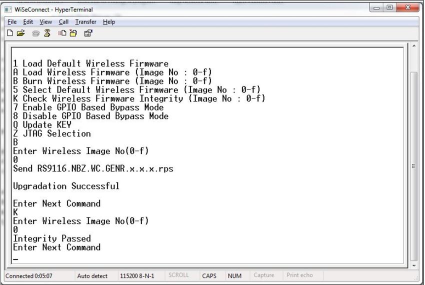
RS9116W BT Classic AT Command Programming Reference Manual
                                                                                                                                       Version 2.4

              6.5.10 Inquiry Complete ................................................................................................................................................... 58
              6.5.11 User Linkkey Request ........................................................................................................................................... 58
              6.5.12 SSP Enable .......................................................................................................................................................... 59
              6.5.13 User Linkkey Save ................................................................................................................................................ 59
              6.5.14 Authentication Complete ....................................................................................................................................... 59
              6.5.15 Mode Change ....................................................................................................................................................... 59
              6.5.16 Disconnected ........................................................................................................................................................ 60
     6.6      SPP Events ..................................................................................................................................................... 60
              6.6.1 SPP Receive......................................................................................................................................................... 60
              6.6.2 SPP Connected .................................................................................................................................................... 60
              6.6.3 Spp Disconnected ................................................................................................................................................. 60
     6.7      BT HID Device mode ...................................................................................................................................... 61
              6.7.1 HID Connected ..................................................................................................................................................... 61
              6.7.2 HID Disconnected ................................................................................................................................................. 61
              6.7.3 HID Handshake Message ..................................................................................................................................... 61
              6.7.4 HID Control Message............................................................................................................................................ 62
              6.7.5 HID Get Report ..................................................................................................................................................... 62
              6.7.6 HID Set Report ..................................................................................................................................................... 63
              6.7.7 HID Get Protocol ................................................................................................................................................... 63
              6.7.8 HID Set Protocol ................................................................................................................................................... 63
              6.7.9 HID Control Data Received................................................................................................................................... 64
              6.7.10 HID Interrupt Data Received ................................................................................................................................. 64
              6.7.11 HID Send Interrupt Data ....................................................................................................................................... 65
              6.7.12 HID Send Control Data ......................................................................................................................................... 65
              6.7.13 HID Send Handshake Message ............................................................................................................................ 66
              6.7.14 HID Send Control Message .................................................................................................................................. 66
              6.7.15 HID Send SDP Configuration Data ....................................................................................................................... 67
              6.7.16 HID Reconnect ..................................................................................................................................................... 67
7    BT Classic Error Codes ......................................................................................................................................... 69
8    BT Power Save Operation ...................................................................................................................................... 75
9    BT AT CMD Configuration Changes/Enhancements .......................................................................................... 78
10   Revision History ..................................................................................................................................................... 79
11   Appendix A: Sample Flows ................................................................................................................................... 81

silabs.com | Building a more connected world.                                                                                                                                   3 | Page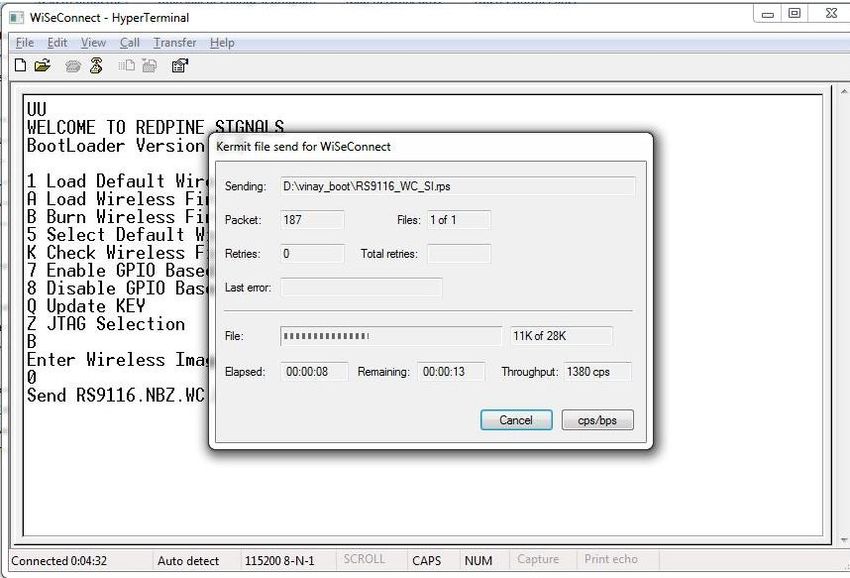
RS9116W BT Classic AT Command Programming Reference Manual
                                                                                                     Version 2.4

About this Document
This document describes the Bluetooth (BT) Classic commands, including parameters used in commands, valid
values for each command, and expected responses from the modules. This document is also used to write software
for host (to control and operate the module).

   Note:
   This document should be used with WiSeConnect version 2.3.0 or later.

silabs.com | Building a more connected world.                                                            4 | Page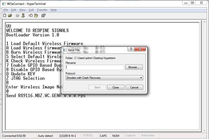
RS9116W BT Classic AT Command Programming Reference Manual
                                                                                                      Version 2.4

1 Overview
Architecture
The following figure depicts the software architecture of the RS9116-WiSeConnect:

                              Figure 1: Architecture Overview for RS9116 WiSeConnect

silabs.com | Building a more connected world.                                                            5 | Page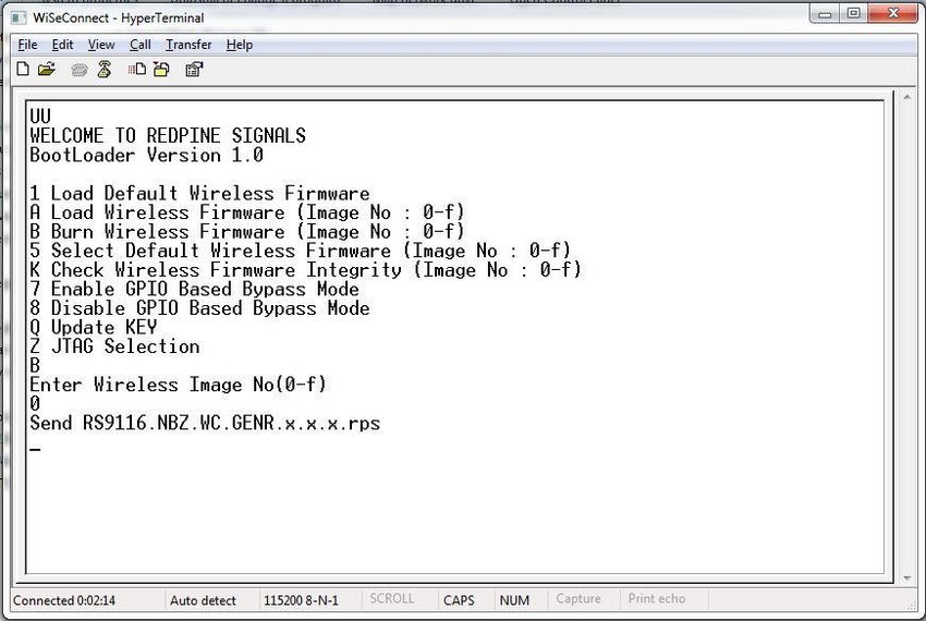
RS9116W BT Classic AT Command Programming Reference Manual
                                                                                                        Version 2.4

Bluetooth Classic Architecture

                                       Figure 2: Bluetooth Software Architecture

Application
The application layer launches the Bluetooth stack and uses commands to access various profiles on remote
Bluetooth devices over the network.
Profiles
There are number of Bluetooth profiles defined in the Bluetooth specification. This design currently supports profiles
including Serial Port Profile (SPP), provided framework to develop new profiles very easily. We will continue to add
new profiles.
Bluetooth Core
The Bluetooth core contains the following higher layers of the stack.
•    RFCOMM
•    SDP
•    L2CAP
•    HCI Generic Driver
•    HCI BUS Driver
RFCOMM is a transport protocol based on L2CAP. It emulates RS-232 serial ports. The RFCOMM protocol supports
up to 60 simultaneous connections between two BT devices. RFCOMM provides data stream interface for higher level
applications and profiles.
The Service Discovery Protocol (SDP) provides a means for applications to discover which services are available and
to determine the characteristics of those available services. SDP uses an existing L2CAP connection. Further
connection to Bluetooth devices can be established using information obtained via SDP.
The Logical Link Control and Adaptation Protocol (L2CAP) provides connection-oriented and connection-less data
services to upper layer protocols with data packet size up to 64 KB in length. L2CAP performs the segmentation and
reassemble of I/O packets from the base-band controller.
HCI Generic Driver – This driver implements HCI Interface standardized by Bluetooth SIG. It establishes the
communication between Stack and HCI firmware in the Bluetooth hardware. It communicates with the Bluetooth
controller hardware via the HCI Bus driver.
HCI Transport Layer Driver – The Bluetooth controllers are connected to the host using interface like UART, USB,
SDIO, SPI, USB-CDC etc. The HCI Transport Layer Driver provides hardware abstraction to the rest of the Bluetooth
stack software. This driver makes it possible to use Bluetooth stack with different hardware interfaces.
Bluetooth Profiles are additional protocols that build upon the basic Bluetooth standard to more clearly define what
kind of data a Bluetooth module is transmitting. While Bluetooth specifications define how the technology works,
profiles define how it is used.

silabs.com | Building a more connected world.                                                                    6 | Page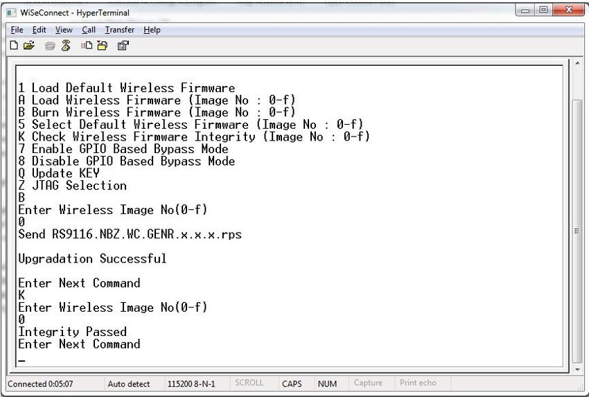
RS9116W BT Classic AT Command Programming Reference Manual
                                                                                                       Version 2.4

The profile(s) a Bluetooth device supports determine(s) what application it is geared towards. A hands-free Bluetooth
headset, for example, would use headset profile (HSP), while a Nintendo Wii Controller would implement the human
interface device (HID) profile. For two Bluetooth devices to be compatible, they must support the same profiles.
OS Abstraction Layer
This layer abstracts RTOS services (semaphores, mutexes and critical sections) that are used by the whole stack and
the applications. The stack, which is designed in an RTOS-independent manner, can be used with any RTOS by
porting this layer. It is also possible to use the Bluetooth stack standalone without RTOS.

silabs.com | Building a more connected world.                                                                  7 | Page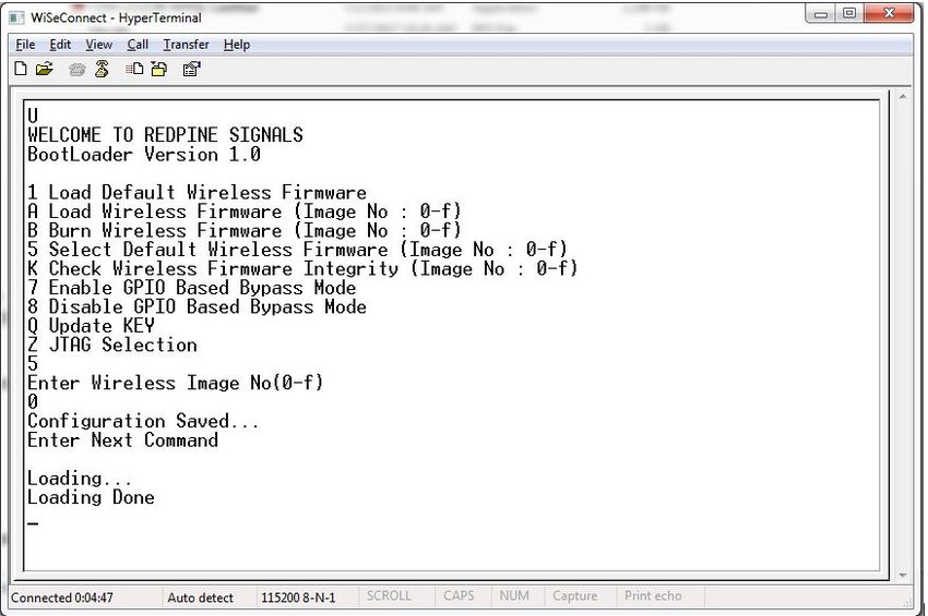
RS9116W BT Classic AT Command Programming Reference Manual
                                                                                                           Version 2.4

2 Bootloader
This section explains features that are supported by the Network and Security Processor (NWP) bootloader. It is
applicable for RS9116 WiSeConnect.
Basic Features
•    Load default firmware
•    Load selected firmware
•    Upgrade firmware from host
•    Selecting default images
•    Enable / Disable host interaction bypass
•    Support for multiple host interfaces (SDIO / SPI / UART / USB / USB-CDC)
•    Firmware integrity check
•    Upgrading Keys
•    JTAG selection
The RS9116W module supports two boot loading modes:
1. Host Interaction (Non-bypass) Mode:
   In this mode host interacts with the bootloader and gives boot up options (commands) to configure different boot
   up operations. The host tells the module what operations it has to perform based on the selections made by the
   user.
2. Bypass Mode:
   In this mode bootloader interactions are completely bypassed and uses stored bootup configurations (which are
   selected in host interaction mode) & loads default firmware image in the module. This mode is recommended for
   final production software to minimize the boot up time.
Host Interaction Mode
In this mode, host interaction varies based on host interface. Host interaction in SPI / USB and UART / USB-CDC are
different. In UART & USB-CDC boot up options are menu based and in SPI / USB using command exchanges. The
details are explained below.
Host Interaction Mode in UART / USB-CDC
This section explains the host interaction mode in UART / USB CDC mode.
Startup Operation
After powering up, host is required to carry out ABRD (Auto baud rate detection) operation. After successful ABRD,
the module displays the menu of bootup options to host. The host needs to select the appropriate option.

    Note:
    On powerup, bootloader checks the integrity of the bootup options. If the integrity fails, it computes the integrity
    from backup. If integrity passes, it copies the backup to the actual location. If the integrity of the backup options
    also fails, the bootup options are reset/cleared. In either of the cases, bootloader bypass is disabled or
    corresponding error messages are given to host. In case of integrity failure and when the backup integrity check
    passes, "LAST CONFIGURATION NOT SAVED" message is displayed. When backup integrity also fails,
    “BOOTUP OPTIONS CHECKSUM FAILED" is displayed before displaying the bootup options.

Hyper Terminal Configuration
RS9116W uses the following UART interface configuration for communication:
Baud Rate: The following baud rates are supported by the module: 9600 bps, 19200 bps, 38400 bps, 57600 bps,
115200 bps, 230400 bps, 460800 bps, 921600 bps.
Data bits: 8
Parity: None
Stop bits: 1
Flow control: None

silabs.com | Building a more connected world.                                                                        8 | Page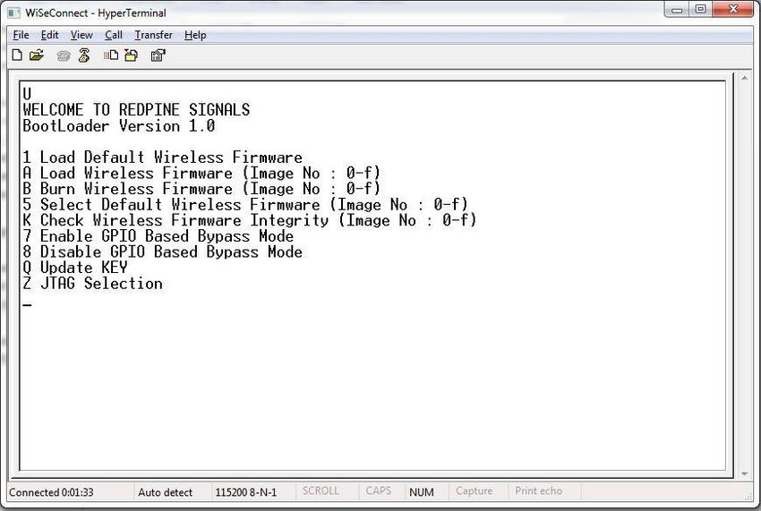
RS9116W BT Classic AT Command Programming Reference Manual
                                                                                                         Version 2.4

Follow sequence of steps as given below:
•    Open Hyper terminal and enter any name in the "Name" field. After this, click "OK" button.
     Here, "WiSeConnect" is entered as shown in the figure below.

    Note:
    Default baud rate of the module is 115200.

                                   Figure 3: HyperTerminal Name field Configuration

•    After clicking "OK", the following dialog box is displayed as shown in the figure below.

silabs.com | Building a more connected world.                                                               9 | Page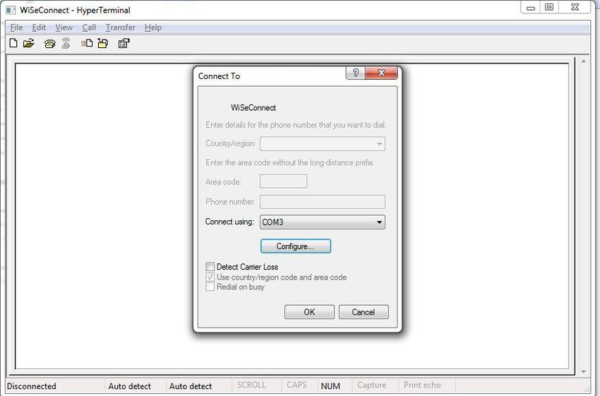
RS9116W BT Classic AT Command Programming Reference Manual
                                                                                                         Version 2.4

                                Figure 4: HyperTerminal COM Port Field Configuration

•    In the "Connect using" field, select appropriate com port. In the figure above COM3 is selected.
     Click "OK" button.
•    After clicking the "OK" button the following dialog box is displayed as shown in the figure below

                                Figure 5: HyperTerminal Baud Rate Field Configuration

silabs.com | Building a more connected world.                                                              10 | Page
RS9116W BT Classic AT Command Programming Reference Manual
Version 2.4
Set the following values for the fields shown in the Figure 6.
• Set baud rate to 115200 in "Bits per second" field.
• Set Data bits to 8 in "Data bits" field.
• Set Parity to none in "Parity" field.
• Set stop bits to 1 in "Stop bits" field.
• Set flow control to none in "Flow control" field.
• Click "OK" button after entering the data in all the fields.
Auto Baud Rate Detection (ABRD)
The RS9116W automatically detects the baud rate of the Host's UART interface by exchanging some bytes. The Host
should configure the UART interface for the following parameters for ABRD detection.
RS9116W uses the following UART interface configuration for communication:
Baud Rate: The following baud rates are supported: 9600 bps, 19200 bps, 38400 bps, 57600 bps, 115200 bps,
230400 bps, 460800 bps, 921600 bps.
Data bits: 8
Stop bits: 1
Parity: None
Flow control: None
To perform ABRD on the RS9116W, the host must follow the procedure outlined below.
1. Configure the UART interface of the Host at desired baud rate.
2. Power on the RS9116W.
3. The Host, after releasing the module from reset, should wait for 20 ms for initial boot-up of the module to complete
and then transmit 0x1C at the baud rate to which its UART interface is configured. After transmitting '0x1C' to the
module, the Host should wait for the module to transmit 0x55 at the same baud rate.
4. If the '0x55' response is not received from the module, the host has to re-transmit 0x1C, after a delay of 200ms.
5. After finally receiving '0x55', the host should transmit '0x55' to the module. The module is now configured with the
intended baud rate.
Note:
Performing ABRD in host interaction mode is must for USB CDC mode.
Figure 6: ABRD Exchange Between Host And Module
silabs.com | Building a more connected world. 11 | PageRS9116W BT Classic AT Command Programming Reference Manual
Version 2.4
Below are the boot-up options, Firmware upgrade and Firmware loading procedures for WiSeConnect Product.
Start Up Messages on Power-Up
After powering up the module and performing ABRD you will see a welcome message on host, followed by boot up
options:
Note:
Windows Hyper Terminal is used to demonstrate boot up /up-gradation procedure.
Figure 7: RS9116-WiSeConnect Module UART/USB-CDC Welcome Message
Loading the default wireless firmware in the module
To load the default firmware flashed onto the module, choose Option 1: "Load Default Wireless Firmware ".
Load Default Wireless Firmware
• After welcome message is displayed as shown in the above figure, select option 1 "Load Default Wireless
Firmware " for loading Image.
silabs.com | Building a more connected world. 12 | PageRS9116W BT Classic AT Command Programming Reference Manual
Version 2.4
Figure 8: RS9116-WiSeConnect Module UART / USB-CDC Default Firmware Loaded
Note:
By default, the module will be configured in AT mode. If mode switch from AT plus command mode to binary
mode is required, then user must give 'H' in the boot-loader options.
The module lasts in the binary mode unless it changed to AT plus command mode and vice-versa.
To change from binary mode to AT mode, then user must give 'U' in the boot-loader options.
Loading selected Wireless Firmware in the Module
To load the selected firmware (from flash) onto the module, choose Option A: "Load Wireless Firmware (Image No: 0-
f)".
Load Wireless Firmware
• After welcome message is displayed as shown in the above figure, select option A "Load Wireless Firmware
(Image No: 0-f)" for loading Image.
• In response to the option A, Module ask to Enter Image No.
• Select the image number to be loaded from flash.
• After successfully loading the default firmware, "Loading Done" message is displayed.
• After firmware loading is completed, module is ready to accept commands
Note:
1. In order to use host bypass mode, the user has to select one of the images as default image by selecting
option 5 (Select Default Wireless Firmware).
2. In Host interaction mode, if no option is selected after bootup menu for 20 seconds then the bootloader will
load selected Wireless default image.
3. If the valid firmware is not present, then a message prompts "Valid firmware not present".
silabs.com | Building a more connected world. 13 | PageRS9116W BT Classic AT Command Programming Reference Manual
Version 2.4
Firmware Upgradation
After powering up the module, a welcome message is displayed.
Upgrade NWP firmware Image
• After the welcome message is displayed, select option B "Burn Wireless Firmware (Image No: 0-f)" to upgrade
Wireless Image.
• The message "Enter Wireless Image No (0-f)" is displayed.
• Then select the Image no to be upgraded.
• The message "Send RS9116.NBZ.WC.GENR.x.x.x.rps" should appear as shown in the figure below.
Figure 9: RS9116-WiSeConnect Module Firmware Upgrade File Prompt Message
• In the "File" menu of HyperTerminal, select the "send file" option. A dialog box will appear as shown in the figure
below. Browse to the path where "RS9116.NBZ.WC.GENR.X.X.X.rps" is located and select Kermit as the protocol
option. After this, click the "Send" button to transfer the file.
• If the valid firmware is not present, then a message prompts "Valid firmware not present".
silabs.com | Building a more connected world. 14 | PageRS9116W BT Classic AT Command Programming Reference Manual
Version 2.4
Figure 10: RS9116-WiSeConnect Module Firmware Upgrade File Selection Message
The dialog box message is displayed while file transfer is in progress as shown in the figure below.
Figure 11: RS9116-WiSeConnect Module Firmware Upgrade File Transfer Message
silabs.com | Building a more connected world. 15 | PageRS9116W BT Classic AT Command Programming Reference Manual
Version 2.4
• After successfully completing the file transfer, module computes the integrity of the image and displays
"Upgradation Failed, re-burn the image" in the case of failure and "Upgradation Failed and default image invalid,
Bypass disabled" in the case of both failure and corruption of the default image.
• In the case of success, module checks if bootloader bypass is enabled and computes the integrity of the default
image selected. If the integrity fails, it sends "Upgradation successful, Default image invalid, gpio bypass
disabled." If integrity passes or gpio bypass not enabled, it sends "Upgradation Successful" message on terminal
as shown in the figure below.
Figure 12: RS9116-WiSeConnect Module Firmware Upgrade Completion Message
• At this point, the upgraded firmware Image is successfully flashed to the module.
• User can again cross check the integrity of the Image by selecting the Option K " Check Wireless Firmware
Integrity (Image No : 0-f)" for Wireless Image.
• Follow the steps mentioned in Loading the Default Wireless Firmware in the Module to load the firmware from
flash, select Option 1 from the above the Figure.
• The module is ready to accept commands from the Host.
Bypass Mode in UART / USB-CDC
Making Default Wireless Firmware Selection
With this option, the host can select the default firmware image to be loaded.
Selecting a valid Image as the Default Image
• After the welcome message is displayed, user can select option 5 "Select Default Wireless Firmware ( Image No:
0-f )".
• The message "Enter Wireless Image No. ( 0-f )" is displayed.
• Then select the Image number
• It is better to check the Integrity of Image before selecting it as Default Image.
• When default image is selected, module checks for the validity of the image selected and displays "Configuration
saved".
silabs.com | Building a more connected world. 16 | PageRS9116W BT Classic AT Command Programming Reference Manual
Version 2.4
Figure 13: Making Image no - 0 as Default Image
Enable/Disable GPIO Based Bypass Option
This option is for enabling or disabling the GPIO bootloader bypass mode.
Enabling the GPIO Based Bypass Mode
If user select option 7, GPIO based Bootloader bypass gets enabled. When this option is selected, module checks for
the validity of the image selected and displays "Configuration saved" if valid and "Default image invalid" if valid default
image is not present. Once enabled, from next bootup, Bootloader will latch the value of UULP_GPIO_2. If asserted, it
will bypass the whole boot loading process and will load the default firmware image selected.
• After the welcome message is displayed, user can select option 5 "Select Default Wireless Firmware (Image No:
0-f)".
• The message "Enter Wireless Image No. (0-f)" is displayed.
• Then select the Image no.
• It is better to check the Integrity of Image before selecting it as Default Image.
• When default image is selected, module checks for the validity of the image selected and displays "Configuration
saved".
• Then select option 7 to "Enable GPIO Based Bypass Mode"
• Module responds to select the host interface in Bypass mode (0 - UART, 1 - SDIO, 2 - SPI, 4 - USB, 5 - USB-
CDC)
• Select the required interface.
• If the default image is valid, then it enables GPIO Bypass mode, otherwise it will not enable the GPIO Bypass
mode.
silabs.com | Building a more connected world. 17 | PageRS9116W BT Classic AT Command Programming Reference Manual
Version 2.4
Figure 14: Enabling the GPIO-based Bypass Mode a) Valid Default Firmware b) Invalid Firmware
Disabling the GPIO Based Bypass Mode
• If host selects option 8, GPIO based bypass gets disabled.
Note:
LP_WAKEUP needs to be de-asserted on power up to move to host interaction mode, to select bootup options
like disable Bypass mode or to change default image.
Check Integrity of the Selected Image
This option enables the user to check whether the given image is valid or not. When this command is given,
bootloader asks for the image for which integrity has to be verified as shown in the figure below.
silabs.com | Building a more connected world. 18 | PageRS9116W BT Classic AT Command Programming Reference Manual
Version 2.4
Figure 15: Integrity Check Passed
Other Operations
This section contains additional, less frequently used boot-loader options.
Update KEY
Note:
This feature is not enabled in current release.
JTAG Selection
Note:
This feature is not enabled in current release.
silabs.com | Building a more connected world. 19 | PageRS9116W BT Classic AT Command Programming Reference Manual
Version 2.4
3 Host Interfaces
RS9116 WiSeConnect Module supports SPI, USB, UART and SDIO for interfacing to host. This section describes
UART interface in detail including the supported features, protocols, and commands.
Only UART and USB-CDC interfaces are supported in AT mode.
Note:
USB and SDIO interfaces are currently not supported.
3.1 UART Interface
This section describes RS9116-WiSeConnect UART interface, including the commands and processes to operate the
module via UART.
UART on the RS9116-WiSeConnect is used as a host interface to configure the module to send data and to receive
data.
Features
• Supports hardware (RTS/CTS) flow control.
• Supports following list of baud rates,
o 9600 bps
o 19200 bps
o 38400 bps
o 57600 bps
o 115200 bps
o 230400 bps
o 460800 bps
o 921600 bps
Note:
For baud rates greater than 115200, it is mandatory to enable UART hardware flow control.
Hardware Interface
RS9916W uses TTL serial UART at an operating voltage of 3.3V.
Host UART device must be configured with the following settings:
• Data bits - 8
• Stop bits - 1
• Parity - None
• Flow control - None
Software Protocol
AT+ command mode
This section explains the procedure that the host needs to follow in order to send Wi-Fi commands frames to the
module and to receive responses from the module in AT+ command mode.
TX Operation
The Host uses TX operations:
1. To send management commands to the module from the Host.
silabs.com | Building a more connected world. 20 | PageRS9116W BT Classic AT Command Programming Reference Manual
Version 2.4
2. To send actual data to the module which is to be transmitted onto the air.
3. If the host receives error code indicating packet dropped, the host has to wait for a while and send the next
command /data.
4. The host should send next data packet only if it receives "OK" response for the previous
one.
Rx Operation
The RS9116W responds with either an 'OK' or 'ERROR' string, for Management or Data frames along with a result or
error code.
The module sends the response/received data to Host in a format as shown below:
Figure 16: RX Frame Format
Note:
If Payload offset is 'x', 'x-4' dummy bytes will be added before Frame Descriptor.
The host needs follow the steps below to read the frame from the Module:
Read 4 bytes using Frame read.
1. Decode Total payload length and payload offset.
2. Read remaining payload by sending Frame to read with (total payload length – 4 bytes), discard Dummy bytes
and then decode Frame descriptor and Frame Body.
silabs.com | Building a more connected world. 21 | PageRS9116W BT Classic AT Command Programming Reference Manual
Version 2.4
4 Classic Command Mode Selection
This section describes AT command mode or Binary mode selection in UART and USB-CDC. It is applicable for
RS9116 WiSeConnect.
After boot-loader interaction, module gives "Loading Done" string in ASCII format to host.
After receiving "Loading Done", based on first command received from host, the module selects command mode.
The module reads first 4 bytes, if it matches with "AT+R", select AT command mode, otherwise select Binary mode.
Once mode is selected, it will remain in same mode until it is reset or power cycle.
There is an option in bootloader to select AT mode or binary mode.
Note:
"AT+R" is not case sensitive.
silabs.com | Building a more connected world. 22 | PageRS9116W BT Classic AT Command Programming Reference Manual
Version 2.4
5 Classic Command Format
This section explains the general command format. The commands should be sent to the Module in the specified
format. It is applicable for RS9116 WiSeConnect. Commands are sent to the module and responses are read from the
module using frame write/frame read (as mentioned in the preceding sections). These commands are called as
command frames.
The format of the command frames is divided into two parts:
1. Frame descriptor
2. Frame Body (Frame body is often called as Payload)
Frame Descriptor (16 bytes) Frame Body (multiples of 4 bytes)
Command frame format is shown below. This description is for a Little-Endian System
Figure 17: Command Frame Format
The following table provides the general description of the frame descriptor.
Table 1: Frame Descriptor
Word Frame Descriptor
Word0 Bits [11:0] – Length of the frame
W0[15:0] Bits [15:12] – 2(indicates Bluetooth packet).
Word1 Bits [15:0] - Packet type
W1[15:0]
Word2 Reserved
W2[15:0]
Word3 Reserved
W3[15:0]
Word4 Reserved
W4[15:0]
Word5 Reserved
W5 [15:0]
silabs.com | Building a more connected world. 23 | PageRS9116W BT Classic AT Command Programming Reference Manual
Version 2.4
Word Frame Descriptor
Word6 1. (0x0000) when sent from host to module.
W6 [15:0] 2. When sent from module to host (as response frame), it contains the status.
Word7 Reserved
W7 [15:0]
Three types of frames will get exchanged between the module and host.
1. Request/Command frames
o These are sent from Host to Module. Each Request/ Command has an associated response with it.
2. Response frames
o These are sent from Module to Host. These are given in response to the previous Request/Command
from the Host. Each command has a single response.
3. Event frames
o These are sent from Module to Host. These are given when there are multiple responses for a particular
Request/ Command frame. This is Asynchronous message to be sent to host.
The following are the types of frame requests and responses and the corresponding codes. The commands are
different for both Classic and LE modes. The below table lists the Command, Response and Event frames in Classic
mode.
In both the modes, the corresponding code is to be filled in W1 [15:0] mentioned in the table above.
Table 2: Command IDs in BT Classic mode
Command Command ID
Set Local Name 0x0001
Query Local Name 0x0002
Set Local COD 0x0003
Query Local COD 0x0004
Query RSSI 0x0005
Query Link Quality 0x0006
Query Local BD Address 0x0007
Set Profile Mode 0x0008
Set Device Discover Mode 0x0009
Get Device Discover Mode 0x000A
Set Connection Mode 0x000B
Get Connection Mode 0x000C
Set Pair Mode 0x000D
Get Pair Mode 0x000E
Remote Name Request 0x000F
Remote Name Request Cancel 0x0010
Inquiry 0x0011
Inquiry Cancel 0x0012
Bond or Create Connection 0x0013
silabs.com | Building a more connected world. 24 | PageRS9116W BT Classic AT Command Programming Reference Manual
Version 2.4
Command Command ID
Bond Cancel or Create Connection Cancel 0x0014
Unbond or Disconnect 0x0015
Set Pin Type 0x0016
Get Pin Type 0x0017
User Confirmation 0x0018
Passkey Reply 0x0019
Pincode Reply 0x001A
Get Local Device Role 0x001B
Set Local Device Role 0x001C
Get Service List 0X001D
Search Service 0X001E
SPP connect 0X001F
SPP Disconnect 0X0020
SPP Transfer 0X0021
Initialize BT Module 0x008D
Deinitialize BT Module 0x008E
Antenna Select 0x008F
Linkkey Reply 0x0091
PER Transmit 0x0098
PER Receive 0x0099
PER Stats 0x009A
PER CW mode 0x009B
Sniff Mode 0x009D
Sniff Exit 0x009E
Sniff Subrating 0x009F
Feature Bit map 0x00A6
Set Antenna Tx Power Level 0x00A7
Set SSP mode 0x00A0
Set EIR data 0X00A9
Add Device ID 0x00EE
Note: A2DP, AVRCP and HFP command IDs are currently not supported.
silabs.com | Building a more connected world. 25 | PageRS9116W BT Classic AT Command Programming Reference Manual
Version 2.4
Table 3: Response IDs in BT Classic Mode
Response Response ID
Set Local Name 0x0001
Query Local Name 0x0002
Set Local COD 0x0003
Query Local COD 0x0004
Query RSSI 0x0005
Query Link Quality 0x0006
Query Local BD Address 0x0007
Set Profile Mode 0x0008
Set Device Discover Mode 0x0009
Get Device Discover Mode 0x000A
Set Connection Mode 0x000B
Get Connection Mode 0x000C
Set Pair Mode 0x000D
Get Pair Mode 0x000E
Remote Name Request 0x000F
Remote Name Request Cancel 0x0010
Inquiry 0x0011
Inquiry Cancel 0x0012
Bond or Create Connection 0x0013
Bond Cancel or Create Connection Cancel 0x0014
Unbond or Disconnect 0x0015
Set Pin Type 0x0016
Get Pin Type 0x0017
User Confirmation 0x0018
Passkey Reply 0x0019
Pincode Reply 0x001A
Get Local Device Role 0x001B
Set Local Device Role 0x001C
Get Service List 0X001D
Search Service 0X001E
SPP connect 0X001F
SPP Disconnect 0X0020
SPP Transfer 0X0021
Initialize BT Module 0x008D
silabs.com | Building a more connected world. 26 | PageRS9116W BT Classic AT Command Programming Reference Manual
Version 2.4
Response Response ID
Deinitialize BT Module 0x008E
Antenna Select 0x008F
Linkkey Reply 0x0091
PER Transmit 0x0098
PER Receive 0x0099
PER Stats 0x009A
PER CW mode 0x009B
Sniff Mode 0x009D
Sniff Exit 0x009E
Sniff Subrating 0x009F
Feature Bit map 0x00A6
Set Antenna Tx Power Level 0x00A7
Set SSP mode 0x00A0
Set EIR data 0X00A9
Add Device ID 0x00EE
Note: A2DP, AVRCP and HFP response IDs are not supported in the v2.1 version of the document
silabs.com | Building a more connected world. 27 | PageRS9116W BT Classic AT Command Programming Reference Manual
Version 2.4
Table 4: Event IDs in BT Classic Mode
Event Event ID
Role Change Status 0x1000
Unbond or Disconnect 0x1001
Bond Response 0x1002
Inquiry response 0x1003
Remote Device Name 0x1004
Remote Name Request cancelled 0x1005
Disconnected 0x1006
User Confirmation Request 0x1007
User Passkey Display 0x1008
User Pincode Request 0x1009
User Passkey Request 0x100A
Inquiry Complete 0x100B
Authentication Complete 0x100C
User Linkkey Request 0x100D
User Linkkey Save 0x100E
SSP Complete 0x100F
BT Mode Changed 0x1010
BT Sniff Subrating Changed 0x1011
BT User Passkey Notify 0x1012
SPP Receive Data 0x1100
SPP Connected 0x1101
SPP Disconnected 0x1102
Note: A2DP, AVRCP and HFP Event IDs are not supported in the v2.1 version of the document
silabs.com | Building a more connected world. 28 | PageRS9116W BT Classic AT Command Programming Reference Manual
Version 2.4
6 BT Classic Commands
This section explains various Bluetooth Classic commands, their structures, parameters, and their responses. For API
prototypes of these commands, please refer to the API Library Section.
Note:
A command should not be issued by the host before receiving the response of a previously issued command
from the module.
6.1 Generic Commands
6.1.1 Set Operating Mode
Description:
This is the first command that needs to be sent from the Host after receiving card ready frame from module. This
command configures the module in different functional modes.
Note:
Opermode must be the first command to be issued as per the system design. Other BT commands should be
only issued after receiving a SUCCESS response for opermode command.
Command Format:
AT Mode:
at+rsi_opermode=
,,,,,,,,,\r\n
Note:
If BIT(31) is set to ‘1’ in custom_feature_bitmap
at+rsi_opermode=,,,\r\n
if BIT(31) is set to ‘1’ in tcp_ip_feature_bit_map
at+rsi_opermode=,,,\r\n
if BIT(31) is set to ‘1’ in both custom_feature and ext_custom_feature bit maps
at+rsi_opermode=,,, \r\n
if BIT(31) is set to 1 in bt_feature_bit_map
at+rsi_opermode=,,,\r\n
If BIT(31) is set to 1 in ble_custom_feature_bit_map
at+rsi_opermode=,,,,\r\n
silabs.com | Building a more connected world. 29 | PageRS9116W BT Classic AT Command Programming Reference Manual
Version 2.4
If BIT(31) is set to '1' in both tcp_ip_feature_bit_map and ext_tcp_ip_feature_bit_map
at+rsi_opermode=,,,
,,\r\n
Command Parameters:
Oper_mode:
Sets the mode of operation. oper_mode contains two parts . Lower two bytes
represent wifi_oper_mode and higher two bytes represent coex_modes.
oper_mode = ((wifi_oper_mode) | (coex_modeRS9116W BT Classic AT Command Programming Reference Manual
Version 2.4
Parameters- feature_bit_map, tcp_ip_feature_bit_map and custom_feature_bit_map are optional in opermode
command in UART mode for AT mode. If user does not give these parameters, then default configuration gets
selected as explained above based on the operating mode configured.
ext_custom_feature_bit_map:
This feature bitmap is an extension of custom feature bitmap and is valid only if BIT[31] of custom feature bitmap is
set. This enables the following feature.
BIT[0]: To enable antenna diversity feature.
1 – Enable antenna diversity feature
0 – Disable antenna diversity feature
BIT[1]:This bit is used to enable 4096 bit RSA key support
1 – Enable 4096 bit RSA key support
0 – Disable 4096 bit RSA key support
Note:
If this bit is enable then connected clients which are in power save may observe packet miss.
BIT[5]: This bit is used to enable Pre authentication Support.
1 – Enable Pre authentication Support
0 – Disable Pre authentication Support
BIT[6]: This bit is used to enable 40MHZ Support
1 – Enable 40MHZ Support
0 – Disable 40MHZ Support
(BIT[20] | BIT[21]) - This bit is used to configure 384k mode.
Note:
It is mandatory to configure 384k mode for any use-case.
1- enable
0-disable
BIT[31]: This bit is used to validate BT and BLE feature bitmap.
1 – BT & BLE feature bitmap valid
0 – BT & BLE feature bitmap is invalid
bt_feature_bit_map:
This bitmap is valid only if BIT[31] of extended custom feature bit map is set.
BIT[0:11] – reserved for future use
BIT[12] – Noise Figure Feature
1 - Enable Noise Figure
0 - Disable Noise Figure
BIT[13] – SNIFF Feature Disable
1- Disable SNIFF Feature
0- Enable SNIFF Feature
BIT[14:19] – reserved for future use
BIT[20:22] – number of slaves supported by BT
Maximum no of BT slaves: 1
silabs.com | Building a more connected world. 31 | PageRS9116W BT Classic AT Command Programming Reference Manual
Version 2.4
BIT [23:29] – reserved for future use
BIT[30] – RF Type selection
1 - Internal Rf Type selection
0 - External Rf Type selection
BIT[31] - Validate BLE feature bit map. For classic opermode this can be ignored.
1 - valid BLE feature bit map
0 - Ignore BLE feature bit map
Note:
A2DP, AVRCP and HFP Profiles are not supported currently.
config_feature_bit_map:
This bitmap is valid only if BIT[31] of ext_tcp_ip_feature_bit_map is set.
Config Feature bitmap Functionality Bit set bit Set Note and Info
to 0 to 1
config_feature_bit_map[0] To select wakeup indication to host. Disable Enable
If it is disabled UULP_GPIO_3 is
used as a wakeup indication to
host.
If it is enabled UULP_GPIO_0 is
used as a wakeup indication to
host.
config_feature_bi_map[1:15] Reserved
config_feature_bi_map[16] Active high or low interrupt mode Disable Enable
selection for wake on wireless
operation
If it is disabled active low interrupt is
used in wake on wireless operation.
If it is enabled active high interrupt
is used in wake on wireless
operation.
config_feature_bi_map[17:23] Reserved
config_feature_bit_map[24:25] Configurability options for 40MHz These bits are used to select
XTAL good time in μs XTAL good time.
BIT(25) BIT(24) Good These changes are available
time from Release 2.3.0 onwards.
Releases prior to 2.3.0 these
0 0 1000
config_feature_bitmap[31:17]
are reserved.
0 1 2000
Its only applicable for customers
1 0 3000 using chip and not the module.
Please contact support for more
1 1 600 details.
Default value is 1000 μs.
config_feature_bit_map[31:26] Reserved for LMAC
Note:
32KHz external clock connection and power save pins
silabs.com | Building a more connected world. 32 | PageRS9116W BT Classic AT Command Programming Reference Manual
Version 2.4
As per Silicon Labs data sheet updated in May 2019, 32KHz external clock and the power save pins
connections have changed. To keep SW compatibility between initial design (i.e., first EVKs developed by
Silicon Labs) and new designs, there are currently 2 options for connecting 32KHz external clock and the power
save pins:
Option 1:
External 32KHz clock connection pins : XTAL_32KHZ_P & XTAL_32KHZ_N
Power Save connection pins : HOST_BYP_ULP_WAKEUP & UULP_VBAT_GPIO_3
Option 2:
External 32KHz clock connection pin : UULP_VBAT_GPIO_3
Power Save connection pins : HOST_BYP_ULP_WAKEUP & UULP_VBAT_GPIO_0
Note:
As per Silicon Labs data sheet updated in May 2019, Option 2 must be used for External 32KHz clock and
Power save connections in new designs.
Response:
Result Code Description
OK Successful execution of the command
ERROR Failure
Example:
AT Mode:
at+rsi_opermode=327680,0,0,2147483648,2150629376,1073741824\r\n
Response:
OK\r\n
bt_loaded\r\n
6.1.2 Set Local Name
Description: This is used to set name to the local device.
AT command format:
at+rsibt_setlocalname=,\r\n
Parameters:
NameLength – Length of the name of local device.
Name (50 bytes) – Name of the local device.
AT command Ex:
at+rsibt_setlocalname=6,silabs\r\n
Response:
OK\r\n
Note:
When the name of the local device is set to a value with length more than 16 bytes then error is returned with an error
code 0x4E66.
silabs.com | Building a more connected world. 33 | PageRS9116W BT Classic AT Command Programming Reference Manual
Version 2.4
6.1.3 Query Local Name
Description:
This is used to query the name of the local device.
AT command format:
at+rsibt_getlocalname?\r\n
Response:
Result Code Description
OK , Command Success.
ERROR Command Fail.
Response Parameters:
name_length - Length of the name
local_device_name (50 bytes)- Name of the local device
AT command Ex:
at+rsibt_getlocalname?\r\n
Response:
OK 8,silabs\r\n
6.1.4 Set Local COD
Description:
This is used to indicate the capabilities of local device to other devices. It is a parameter received during the device
discovery procedure on the BR/EDR physical transport, indicating the type of device. The Class of Device parameter
is only used on BR/EDR and BR/EDR/LE devices using BR/EDR physical transport. It is defined in the following link
"https://www.bluetooth.com/specifications/assigned-numbers/".
AT command format:
at+rsibt_setlocalcod=\r\n
Parameters:
local_device_class – Class of the Device of local device
AT command Ex:
at+rsibt_setlocalcod=7A020C\r\n
Response:
OK\r\n
6.1.5 Query Local COD
Description:
This is used to query Class of Device of the local device.
AT command format:
at+rsibt_getlocalcod?\r\n
Response:
Result Code Description
OK Command Success.
ERROR Command Fail.
Response Parameters:
local_device_class – Class of the Device of the local device
silabs.com | Building a more connected world. 34 | PageYou can also read