WVU BALLOON SATELLITE INSTRUMENTATION BOARD
←
→
Page content transcription
If your browser does not render page correctly, please read the page content below
WVU BALLOON SATELLITE INSTRUMENTATION BOARD
                     G. Michael Palmer, K8LG
                   WEST VIRGINIA UNIVERSITY
     DEPARTMENT of MECHANICAL AND AEROSPACE ENGINEERING

A.     INTRODUCTION
In the fall of 2002 I was approached about helping with the first WVU Balloon Satellite
course to be offered in the spring term. Being an amateur radio operator, interested in
instrumentation, and micro-controllers the fit seemed too good to be true. In addition I
was retiring as a full time faculty member at the start of 2003 and could dedicate nearly
full time to the project.

The course was to be offered in the Mechanical and Aerospace Engineering Department
but open to students from any discipline within the University. Since not all students
would be from engineering it was decided to put the emphasis on the design,
construction, and testing of a balloon package to make “measurements” during flight. To
this end we would use “off the shelf” instrumentation packages such as the HOBO data
logger as well as packages we would design and build for this project. The WVU
Balloon Satellite Instrumentation Board shown here is the result of this in house
development. We are now flying the second and third generations of this board and will
report here on the second-generation board (Version 2.2 board) only. The Version 3
board is more specialized for higher speed applications (e.g. accelerometers at 50 Hz
sampling rate).

B.      DESIGN - HARDWARE
The design criteria for the hardware included the following considerations:
          • Low power consumption
          • Operation from 1 or 2 cells (1.5 or 3 Volts)
          • Bell 202 packet radio MODEM (APRS and telemetry)
          • Radio interface for APRS transmission
          • Serial I/O for GPS receiver and configuration
          • Multi-channel 12 bit ADC (single ended or differential input)
          • Timer for resistive (thermistor) and capacitive transducers
          • Timed pulse outputs
          • Period/frequency input
          • SPI interfaces for SPI transducers and devices
          • LED output for diagnostic and operational status
          • Onboard memory to allow recording data for the flight duration
          • Small size and weight
          • Low cost

These design criteria have been met or exceeded in the Version 2.2 board.

                                           1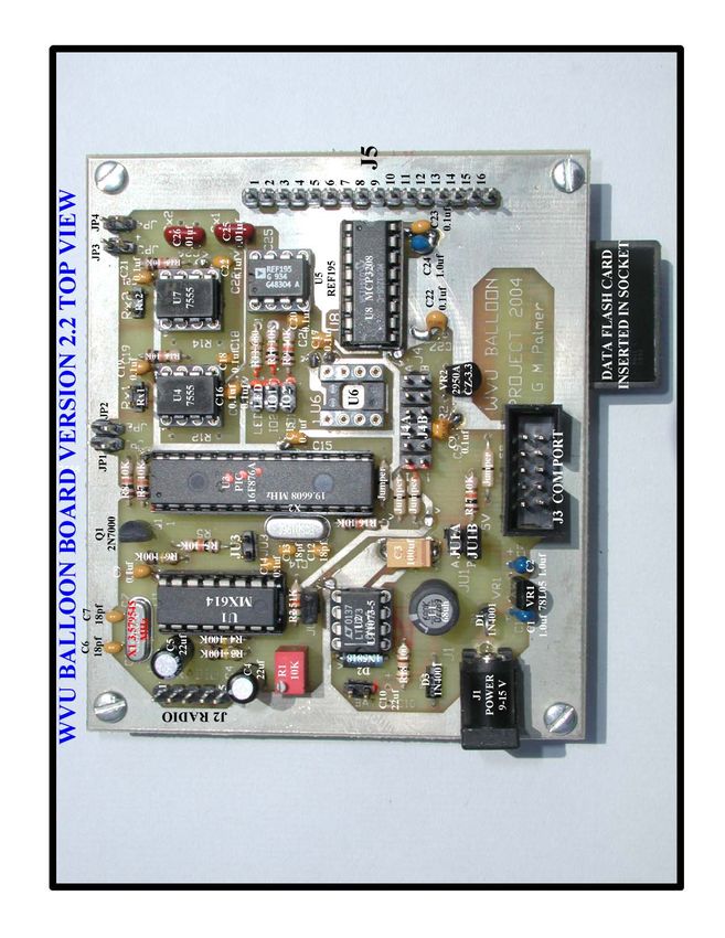
POWER SUPPLY
The board contains two independent power supplies that deliver +5 Volts to the board
and to attached transducers/devices. One power supply uses a standard linear regulator
and consists of diode D1, capacitors C1 and C2, and 5 Volt regulator VR1 (See Appendix
B for schematic diagram). This supply is connected to the 5 Volt buss on the board via
jumper block JU1-B and is intended for use in the laboratory during testing. The input to
this power supply can be in the 7 to 15 Volt via the 2.1mm power connector J1.

The second power supply uses a switching regulator in step-up mode and consists of
diodes D2 and D3, resistor R18, inductor L1, capacitor C3, and integrated circuit U2
(LT1073-5). This power supply is connected to the 5 Volt buss via jumper block JU1-A
and is intended for use in flight. The input voltage is from two cells (AAA or AA) via
the 2 pin BAT connectors. The efficiency of this switching power supply is about 80 to
85%. In use only one of the power supplies would be connected to the 5 Volt buss at a
time.

The 5 Volt current drain of the board is about 12 to 20ma depending on the number and
type of IO devices connected. This translates in to an operational life of over 24 hours on
two alkaline AAA (1100 ma-hr) cells when using the switching power supply. When
using alkaline batteries they must be kept above 0°C to get the service life indicated.
Better low temperature performance may be obtained by using two 1.5 Volt Lithium
cells.

       MODEM and RADIO INTERFACE
The Bell 202 modem consists of a MXCOM MX614 (U2) integrated circuit and
associated components. The MX614 is connected to a radio via the 5-pin header J2
(RADIO). This header has pins for Receive audio, Transmit audio, PTT (Push To Talk)
and Ground and is suitable for connection to most radios. Variable resistor R1 and
jumper block JU2 are used to adjust MODEM transmit audio level into the radio. The
audio input to the modem can vary of a wide range and still decode.

The digital side of the MODEM is connected to the board’s processor (U3 PIC16F876A-
I/SP). The digital signals are: transmit data, receive data, carrier detect, and M0 and M1
mode select lines. The PIC will encode (decode) the AX.25 frames.

        SERIAL INTERFACE
A TTL level 4800-baud serial interface is provided at the 10-pin connector J3. The
signals on this connector are: TXD, RXD, RTS, CTS, GND, and +5 Volts. This
connector may be connected to a GPS receiver (with TTL levels) or to a TTL/RS-232
level connector. We have been using the Motorola Oncore GT PLUS 8-channel receiver
that has TTL levels. If other GPS receivers are used provisions must be made for level
conversion.

The serial interface is also used to communicate with the PC during configuration and
data downloading. We use a level converter that converts between TTL level board
signals and RS-232 level PC COM port signals. A photo and diagram of the level

                                            2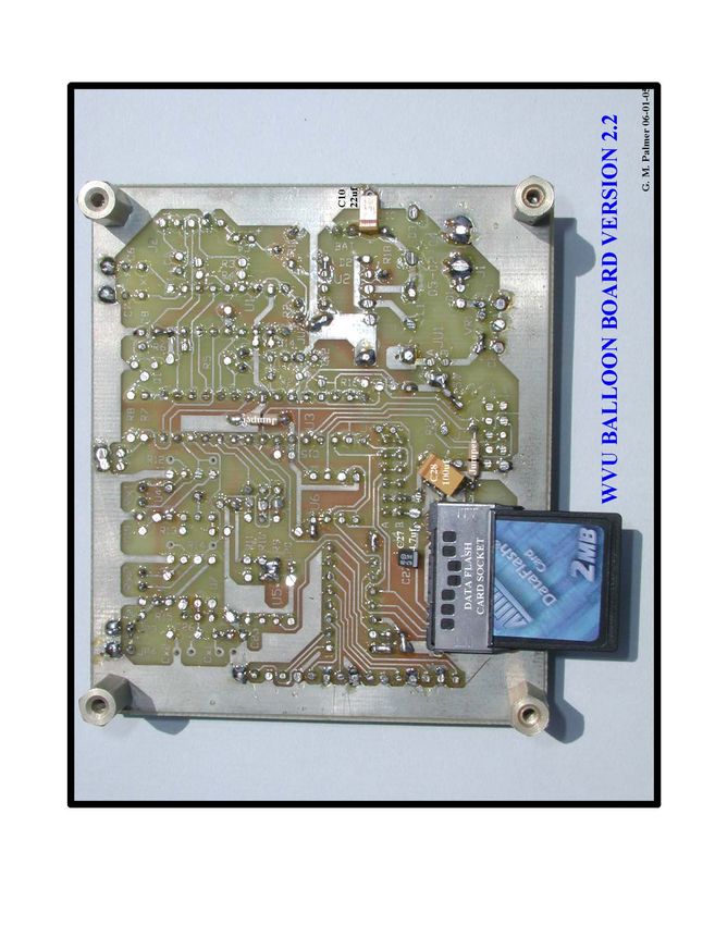
converter we are using is given in Appendix E. Power for this level converter is provided
via pin 10 of J3.

    ANALOG to DIGITAL CONVERTER
An 8 channel multiplexed 12-bit analog to digital converter with an SPI interface
provides inputs for analog transducers. The ADC uses a MCP3208 or MCP3304 (U8)
and connects to transducers via the 16-pin SIP connector (J5). Even pins are inputs and
odd pins are ground. The ADC reference voltage is provided by U5 and may be 5.000
Volts (REF195), 4.096 Volts (REF198), or 2.048 Volts (REF191). The MCP3208 will
provide 8 single ended inputs and the MCP3304 may be configured for 4 differential
inputs (13 bit conversion). All ADC inputs are unipolar.

The digital side of the ADC is connected to the PIC processor via the boards SPI buss
and an additional chip select line.

        TIMERS (RESISTIVE and CAPACITIVE TRANSDUCERS)
Two CMOS 7555 timers (U4 and U7) are included primarily for use with thermistors.
These timers can be used in resistance mode by placing fixed capacitors on the board at
C25 and C26 and connecting resistive transducers to the Rx1 and Rx2 headers or
capacitive mode by placing fixed resistors on R12 and R14 and capacitive transducers on
headers Cx1 and Cx2.

The outputs of the two Timers are connected to input pins on the PIC processor. The data
is read in the form of the period count for the input square wave. For temperature
measurements we have been using YSI 44003A 1000Ω@25°C on the timer inputs.

        PULSE OUTPUTS and PERIOD/FREQUENCY INPUTS
There are two independent pulse outputs that are used for generating TTL output pulses
at evenly spaced periods (multiples of 10 seconds) and of fixed widths (multiples of 10
milliseconds). One of these outputs will rest at low level and pulse to a high level and the
other will rest at a high level and pulse to a low level. The two pulse output lines are
connected to the 2-pin SIP headers at IO1 and IO2 on the board. These lines can sink
about 20ma each and may be used to drive a 5 Volt DIP relay. The status of these lines
will be recorded in the Flag byte data field.

       DIGITAL and SPI INTERFACE
The PIC processor lines brought out to the two SIP headers J4A and J4B may be used for
several functions and programmed independently on each interface. They may be
programmed (via configuration program) as:

                   •   Period measurement input waveform (square wave).
                   •   Frequency measurement input wave form (square wave)
                   •   SPI interface
                   •   NO FUNCTION

                                             3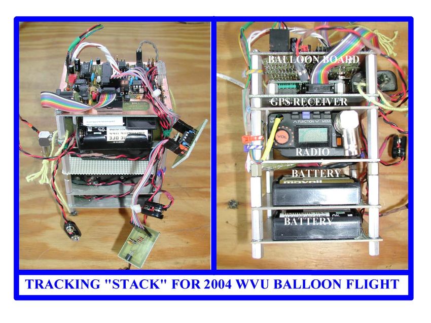
The CS lines in the interface are used for period/frequency input.         There will be
magnitude limitations for period /frequency measurements.

When used as SPI interface the signals on these connectors J4A and J4B are DIN,
DOUT, CLK, CS, VCC, and GND. The transducers and devices connected may get their
power via the VCC/GND pins. We have used these connectors for a number of different
devices. At the present time there is code in place to support the following:

                  •   TC77 digital temperature transducers
                  •   DALLAS (DS1306) Real Time Clock (RTC)
                  •   MCP3201 ADC (single ended input)
                  •   MCP3301 ADC (differential input)

The PIC code makes provisions for up to 7 different devices.       To add a new device a
device driver must be written and assembled into the PIC code.

        LED OUTPUT
As we used the Balloon Board it became apparent there was need for an indication of the
status of operational parameters. The LED output provided this function. The two pins
of the LED header are used to connect a LED. A current limiting resistor of 860 Ohms
(R11) is provided on the board. The LED functions as set by the configuration program
are:

                  •   Flash on starting data logging
                  •   Flash on each data logging scan
                  •   Flash on each radio transmission
                  •   Flash on each GPS radio transmission
                  •   Flash every 10 seconds during data logging

The duration of a “Flash” is one second. During most flights the LED mode is set to
flash on entering data logging and on each data scan.

The LED is also used to indicate correct initialization and start of board firmware by
giving three short flashes on power up, leaving data logging mode, and other firmware
restarts. To confirm the correct connection of the LED to the LED connector it may be
flashed by the “C” (calibrate) command from the configuration software.

       DATA MEMORY and CONFIGURATION MEMORY
Data collected in data logging mode is stored in an ATMEL Data Flash card. A 2MB
card will store up to 16,384 128 byte records (one per scan). Each record will contain the
point number, data for 8 analog channels, data for two timers, data for two SPI devices,
GPS altitude (if GPS receiver is connected), Flag byte, and the raw GPS data ($GPGGA
sentence). Using a data-logging period of 10 seconds the 2MB card will store data for
over 45 hours.

                                            4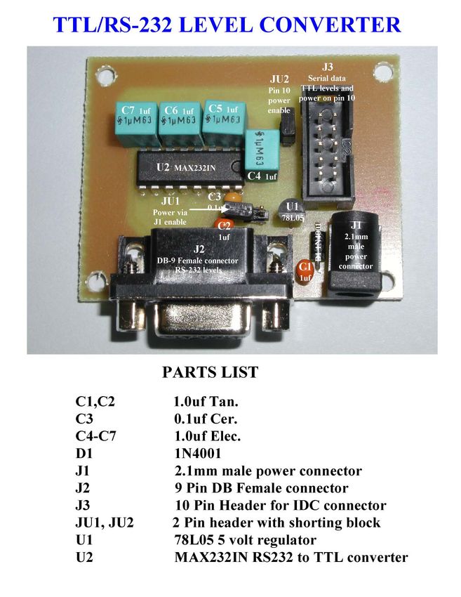
Data stored in the Data Flash card may be down loaded to an ASCII or a Binary data file
using the configuration program. The ASCII data will be presented as comma delimited
data. Balloon Board configuration information is stored in the non-volatile EEPROM in
the PIC processor.

       SIZE, WEIGHT and FROM FACTOR
The Version 2 board is built on a 4.7 by 3.2 inches rectangular 1/16-inch thick FR-4
double-sided circuit board stock using conventional through-hole technology and has a
weight of 65g when populated. All integrated circuits are placed in double wipe sockets
to allow ease of replacement of any defective components, although this has not been
necessary.

The through-hole form factor for this board was determined by our ability to produce the
circuit boards in our facility. The size and weight of the board could be reduced by the
use of SMT.

        COST
The cost of components for the Version 2 board may be calculated using the Bill of
Materials in Appendix D. The costs will vary as time changes. A current estimate of the
cost of materials is about $75 when buying components at smallest quantities. A list of
vendors for components is also provided in Appendix D.

        DUAL SIP HEADER CONNECTORS
We have used SIP headers freely on the board because of their low cost, small size, and
ease of use. Many of our transducers and devices need to be connected via the mating 2
pin female SIP connectors. We have found a ready supply of these in old PCs that are
being scrapped. Here you find cables with connectors and LED, cables with switches,
and many other goodies.
C.     SOFTWARE
The software for the Balloon Board consists of two parts: the firmware in the

                                           5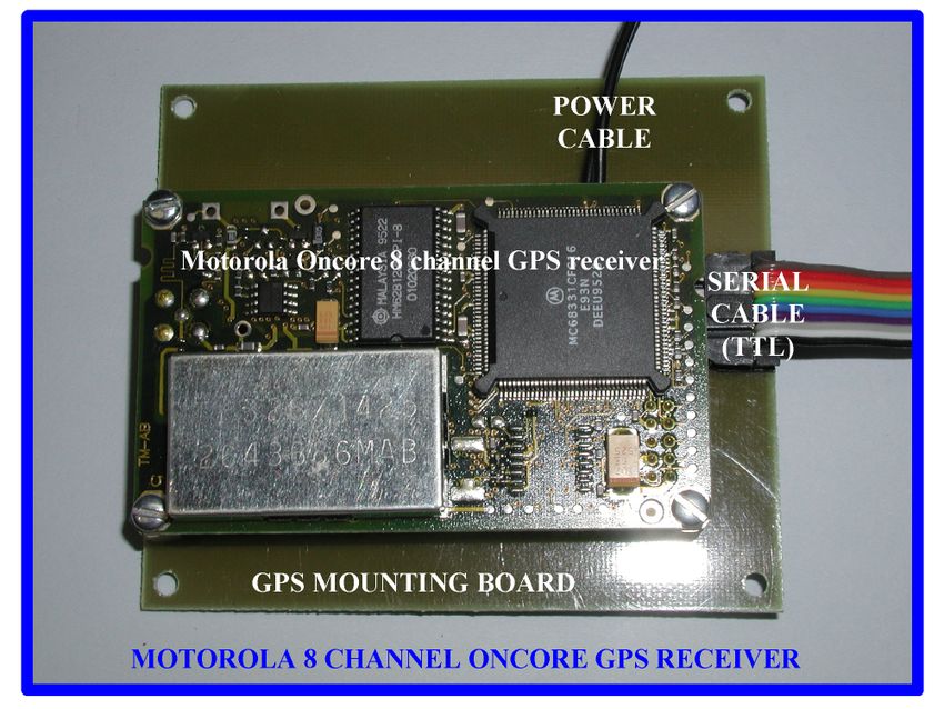
PIC16F876A processor on the board and the PC configuration software. The PIC
firmware is unchangeable by the user and will respond to user commands in “HOST”
mode.

The configurations program communicates with the board via the serial interface using a
host mode protocol. In host mode the user may set the board configuration and down
load data logger data from the board. Configuration information is stored in the
PIC16F876A’s non-volatile EEPROM.

      CONFIGURATION ITEMS
The configuration program allows the user to set 31 items and store them in the boards
EEPROM. These items are:

          •   Amateur Radio call sign for board radio transmissions
          •   “TO” call sign for board radio transmissions
          •   First digipeater call sign for board radio transmission
          •   Second digipeater call sign for the board radio transmission
          •   Data logging period in units of 10 seconds
          •   Radio transmission period in units of data logging period
          •   Radio GPS transmission in units of Radio transmission period
          •   Data logging speed: Slow or Fast (Only SLOW speed covered)
          •   Analog channels 1 through 8 labels (8 character user defined title)
          •   Timer 1 and 2 labels (8 character user defined title)
          •   Digital 1 and 2 labels (8 character user defined title)
          •   Digital 1 and 2 MODE
          •   IO1 and IO2 data direction
          •   IO1 and IO2 period in units of 10 seconds
          •   IO1 and IO2 pulse width in units of 10 milliseconds
          •   LED on/off flag
          •   LED mode.
          •   ID Information a 32 character user defined field

Each of the 31 configuration items has “HELP” information available by typing the item
number followed by a question mark (example: 3? for information about Digipeater 1
field.

                                            6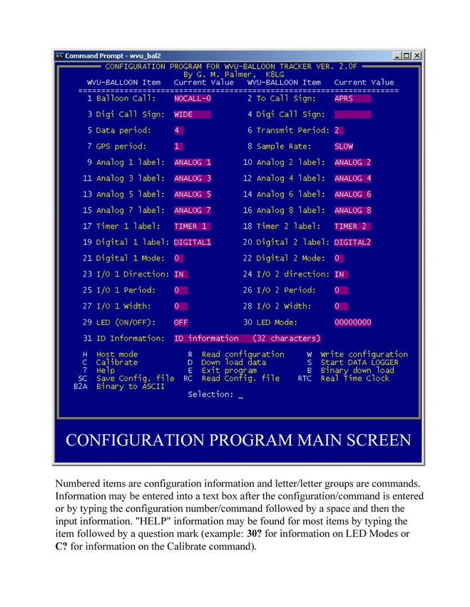
7
COMMANDS
In addition to the 31 configuration items the program has the following commands:

           •   “H”   Enter Host mode communications between board and PC
           •   “R”   Read (and display) configuration data from the board’s EEPROM
           •   “W”   Write current configuration information to the board’s EEPROM
           •   “C”   Read data from analog channels, timers, and digital inputs and
                     Display the values. Also flashes the LED.
           •   “D” Down load data stored in the memory card to a data file on the PC
           •   “S”   Start the data logger
           •   “?”   Display help screens
           •   “E”   Exit configuration program
           •   “B” Binary down load data stored in the memory card to a PC file
           •   “SC” Save the current configuration to a PC file
           •   “RC” Read a configuration from a PC file and restore to the board’s
                     EEPROM
           •   “RTC” Real Time Clock functions. If there is a DALLAS RTC
                     Configured on Digital channel 1 this command will set or read it.
           •   “B2A” Binary to ASCII conversion function. Convert binary file to
                     ASCII file.
           •   “V” Display Version of the board/software.
           •   “VI” Display Version information and options.

Many of the commands have “HELP” information available by typing the command
followed by a question mark (example: D? for information about the Down Load
command).

        HOST MODE CONNECTION
The balloon board is connected to the PC’s serial port via the TTL/RS-232 Level
Converter. A 10-conductor ribbon cable with 10 pin female IDC connectors on each end
is used to connect the level converter to the board. A standard serial cable with female/
male DB-9 connectors is used to connect the level converter to the PC’s serial port. The
level converter is supplied with 5V via pin 10 of the ribbon cable.

After all the cables have been connected, power applied to the board, and the
configuration program started communications can be established between the program
and the board by the “H” (Host Mode) command. If the COM port has not been given on
the DOS command line the user will be prompted to choose either COM1 or COM2.
After issuing the “H” command the configuration stored in the board’s EEPROM will be
down loaded and displayed. The number of data points stored in the memory card will
also be displayed in the lower right corner of the screen.

Memory card data may be down loaded to a PC data file with either the “D” command
that stores the data in ASCII format with columns separated by commas or the “B”
command that stores the data in binary format. Since the serial communications data rate
is 4800 baud, down load times may be quite long.

                                           8
CONFIGURATION
Initial configuration of the board is accomplished after entering host mode. Edit the
configuration fields on the screen by typing the item number at the selection prompt and
entering the data as needed. You may also type the number followed by a space and the
parameter for the field, for example ”3 WIDE2-2” to set digipeater 1 field. This will
bypass the screen window for the item. After the edit of the configuration is complete the
information is stored in the board’s EEPROM via the “W” command. This command
will do a “read after write” to insure the data is stored correctly. The configuration may
also be stored as a PC file using the “SC” command. The file name should have an
extension of “.CFG”. To reconfigure or changing individual configuration items enter
host mode, edit the item(s), and write the changed configuration using the “W”
command.

        CALIBRATION FUNCTION
The “C” command allows the user to display the values of the analog channels, the
timers, and the digital inputs on the screen. In addition it will flash the LED allowing
confirmation of the correct LED connection. Uses for the ”C” command we have found
are:
           • Calibration of the timer channels using precision resistors
           • Confirmation of correct LED operation
           • Confirmation of correct temperature sensor operation
           • Calibration of analog sensors
           • Confirmation of data field names
           • Overall view of flight data before launch
           • Confirmation of wiggle-in/wiggle-out on data channels

                                            9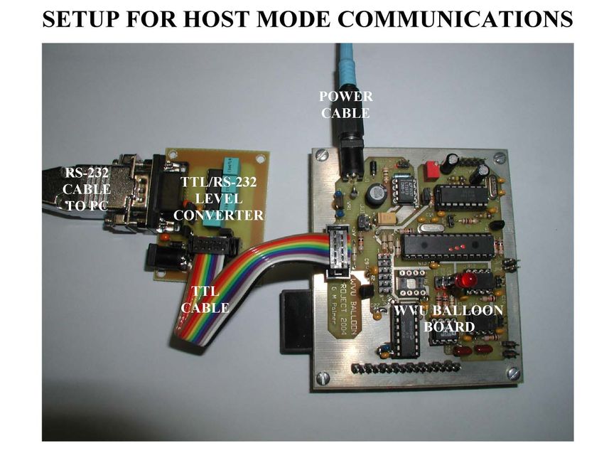
10
START DATA LOGGING
Starting the data logging (and confirming start) is the most critical part of any flight. We
have had more than one case of failure to go into data logging mode at launch time.
Great care has been taken in this design to make it possible to get a positive indication of
start.
While in host mode the data logging may be started or enabled by the “S” command. The
result of the ”S” command is determined by the status of jumper block JU3. If a jumper
is NOT on JU3 data logging is started as soon as the command is issued. If the jumper is
on JU3 data logging will not start until the jumper is removed even if the power is
removed and reconnected.
Deferred start of data logging has the advantage of allowing the board to be completely
setup for operation before starting logging. The board may have logging enabled with
the jumper on JU3, powered down, moved into the flight package, re-powered, and then
started by removing the jumper. Following this procedure eliminates the need for a
connection to the configuration program at launch time.
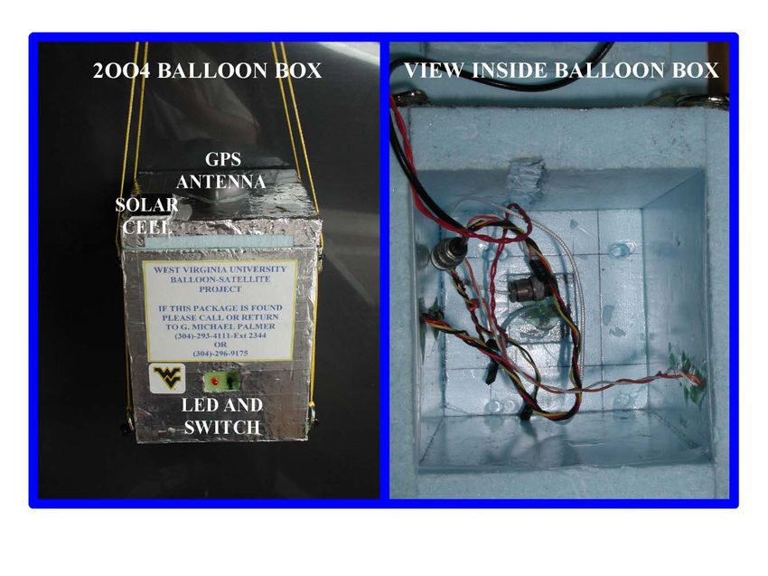
Connecting JU3 to a switch on the outside
of the package provides an easy way to
start data logging at launch time. Adding
an LED to the outside of the box
(connected to the LED block) will provide
a positive and clear indication of the data
logging start. The photo at the right shows
a switch and LED on the outside of a
package.
ENDING DATA LOGGING
Data logging may be exited in several ways:
• Replacing the jumper on JU3 (requires 4 additional scans to stop)
• Connecting to a PC and entering host mode with “H” command
• Data memory card full (unlikely in SLOW mode)
• Loss of power (up to last 16 scans may be lost)
The loss of power exit is not recommended although we have had this happen more than
once on “hard” landings. The loss of data occurs because the number of data scans is
only updated in EEPROM every 16 data scans during normal operation. The other exit
modes will store the number of data scans when closing out logging. Here again it is nice
to have a switch on the lines from JU3 and an LED on the outside of the package that will
terminate logging and provide a visual indication of end of logging.
11DOWN LOADING DATA
After the balloon flight data collected may be moved from the memory card to a PC file.
The “D” or the “B” commands may be used to move the data to the PC via the serial port.
The “D” command moves the data in ASCII column format to a data file. The file will
contain a header with much of the information from the configuration, column headers
and columns of data. The data in the columns is separated by commas and is specifically:
• One column of Point Number
• Eight (8) columns of ADC data
• Two (2) columns of Timer data
• Two (2) columns of Digital data
• One column of GPS altitude parsed from the GGA sentence
• One column of Flag data
• One field containing the raw GPS data
There will be a maximum of about 300 characters per line of data depending on the
presence of the GPS field. Down loading with the “D” command will be a slow process
as the serial port speed is only 4800 baud or 480 characters per second. A typical data
file will be 1800 data points (data logging every 10 seconds for period of 5 hours) will
require a down load time of about 20 minutes. The file extension for the ASCII file
should be “.DAT”
The “B” command moves the data in binary format to a data file. This file will contain a
256-byte header containing all the configuration information plus one 128-byte record for
each data point. The binary down load will be less than half that of the “D” command.
Once data is received in binary format it may be converted to ASCII format using the
“B2A” command. The file extension for the binary file should be “.BIN”.
12D. TYPICAL TRANSDUCERS and INTERFACES
We have used a number of different transducers with this balloon board. Several of these
will be given below as examples of the type of measurements that may be made.
TEMPERATURE
The inside and outside temperatures of our balloon packages have been measured using a
variety of off the shelf transducers. Here we will discuss the following:
• Thermistor temperature transducers
• Solid state analog temperature transducers
• Solid state digital temperature transducers
We have not used thermocouples because of the complexity of the signal conditioning
nor have we used RTDs because of cost.
THERMISTORS
Thermistors are devices that change resistance with temperature. We have used the NTC
(negative temperature coefficient) devices made by YSI (Yellow Springs Instruments).
The most useful have been the devices that have 1000 ohms at 25°C. YSI makes several
others devices that are used by NASA in space flight but the cost becomes an issue. Data
on specific YSI thermistors may be found at their WEB site www.YSI.com. Here you
will find Excel spread sheet data for their devices.
The thermistors are connected to the resistive input of the Timers and high quality 0.01µf
capacitor is connected to the C25 and C26. The output of the timer will now be related to
the resistance of the transducer (see data sheet for ICM7555 timer). To obtain accurate
temperature data the raw data from the timer is processed through a two-step process.
The raw data is first converted to resistance via a calibration curve for the Timer channel
13and then the resistance value is converted to temperature by a look-up table technique
using the YSI data for the specific thermistor being used.
SOLID STATE ANALOG TEMPERATURE TRANSDUCERS
There are a number of solid state temperature transducers available. We have used the
National Semiconductor LM34/LM35 on several flights. These devices have the
advantage of providing a high level linear signal that is 10mV per degree (°F – LM34 or
°C – LM35) over a wide temperature range. One has to be sure to obtain the higher
quality units for outside temperature measurements. The biggest draw back to the use of
these transducers is the need for differential input (or two inputs) when used from a
single power supply. The data sheet for the LM34/LM35 describes how this may be
done.
Although we have not used them, there are other analog transducers that will provide a
signal out that is 10mV per °K (LM135, AD590). These would appear to be a good
choice for use as there would be no problem with a single voltage 5V power supply.
SOLID STATE DIGITAL TEMPERATURE TRANSDUCERS
A number of vendors make digital temperature sensors. We have limited our interest to
those that conform to the SPI interface specification. The 13-bit Microchip TC77 digital
temperature sensor is a good device and provides a two’s complement 13-bit digital
signal that is 16 times the temperature in °C. We have used these for both inside and
outside measurements. We are not recommending the TC77 for outside measurement.
14PRESSURE MEASUREMENTS
Atmospheric pressure may be measured using several off the shelf pressure transducers.
We have used the All Sensors Corp. 0-15 PSIA transducers with high-level outputs.
These units have a supply voltage in the 5V range and an output of 0 to 4.5V, which is a
good match to the ADC inputs on the board.
We have also used the 0-15 PSIA 60-90 millivolt output sensors with bridge amplifiers.
These are much more complicated to use because of the need for offset adjustment and
differential input to accommodate the bridge power/output issues when using a single
power supply.
There are digital pressures sensors using the SPI interface that look good. We have not
yet used any of these but hope to do so in the future. In order to get good data with any
of the pressure sensors at high altitude it is necessary to calibrate them at low pressure.
15CAMERA INTERFACE
We have included digital cameras in many of our packages. The problem of triggering
the camera periodically was solved by attaching wires across the camera’s trip switch,
bringing the wires out to a two-pin SIP connector, and using a relay to trip the shutter. A
small 5V DIP relay is connected to the output of IO2, which rests at a high level and
drops to ground. IO2 output is programmed to pulse at the interval desired and the width
is set to a value that will trip the camera. The IO2 input will sink 20ma, which is more
than that needed for the DIP relay. Five volt power for the relay is provided on one of the
4 JPx headers.
16GPS MEASUREMENTS
The position and altitude of the balloon package may be recorded and broadcast via radio
when a GPS receiver is connected to the serial port. The balloon board software is
configured to use the Motorola Oncore series GPS receivers using the NMEA $GPGGA
sentence. This sentence is used because it has both longitude/latitude and altitude data.
The period between GPS radio transmissions may be set with the radio transmit period
and the GPS period in the configuration file. If the GPS is present and active GPS data
will be recorded each data scan and stored in the memory card. The transmission period
for APRS data is set to 1 minute for our balloon flights.
We have used both the Motorola Oncore M12 12 channel receiver and the Motorola
Oncore GT Plus 8 channel receiver. Both of these receivers support a Motorola binary
command format and the more standard NMEA format. Most of our flights use the 8-
channel receiver because of its low cost ($25-$40 on Ebay and at flea markets) even
though it has somewhat higher power consumption (5V @ 200ma). Both receivers will
need to be set up initially using the Motorola Oncore setup program (available at
www.oncore.motorola.com). If the receiver has no backup battery one may be attached
on the supporting board. We use a Panasonic (ML1220/V1AE) 3 Volt rechargeable
Lithium cell as recommended for the GT Plus receiver.
When using the Motorola Oncore program to setup the GPS receiver you will need to
Place a jumper on JU1 of the Level Converter board and power it from an external
source. A null-modem will be needed between the output of the GPS receiver and the
17input to the Level Converter board. Once the board is configured and in the 4800 baud
NMEA mode the back up battery will hold the setting for several months.
The bottom of the GPS board is shown below. This board is designed to stack under the
main Balloon Board.
The Null Modem placed in line with the data cable from the Oncore GPS receiver is
shown below. This cable crosses the TTL signal lines: TXD/RXD, RTS/CTS, and
DSR/DTR from the GPS receiver to the Level Converter.
18E MORE INFORMATION
This project has been very satisfying and a great deal of fun for all involved in the
balloon project at West Virginia University. We have been lucky with our launches over
the more than three years we have been doing this project and recovered all the packages
in good condition. A number of the local amateurs have been very helpful in the tracking
and recovery effort.
The first year (2003) we really didn’t know what we were doing but managed to track the
APRS signal to the balloon but were totally unprepared for removing the packages from
the tops of 80 feet trees. We came back one week later with a tree climber and recovered
the packages! Even though the packages hung in the trees for a week in the rain all the
data was intact and photos (the ones that took) were fine.
The second year (2004) we went prepared with a tree climber among the crew. Sure
enough the packages were even higher in the trees but were recovered in fine shape with
all their data.
The most disastrous launch was on Halloween day 2004. This was a launch sponsored by
several graduate students and faculty. We had two APRS tracking packages on the
balloon but neither worked! The first package (mine) was a simple radio, GPS receiver,
and PIC based tracker (unit developed in house). I had made the software too polite and
it could not find clear air to transmit once at altitude. The second was part of an
instrumentation package using a Version 2 board. At launch we had to do a restart of the
firmware and failed to plug the GPS serial cable into the Balloon Board. It would
transmit telemetry but no GPS data. The good news: one of the crew had done a very
good job with the landing prediction software. We were able to drive to the predicted
landing location and hear my package after it landed. Needless to say I fixed the tracker
firmware to do unrestricted transmission when in balloon service.
Our two launches in the spring of 2005 went off with hitches. One required a tree
climber to recover the packages and the other landed in a meadow.
We are willing to share information on our hardware, software, and experiences with any
one interested in academic Balloon Satellite launches. Please feel free to contact me at:
gmpalmer@adelphia.net
Mike Palmer, K8LG
2302 Surrey Drive
Morgantown, WV 26505-2940
19APPENDIX A WVU BALLOON TRACKING STACK
Tracking for the 2004 WVU balloon flight was tracked using the Version 2.2 balloon
board. The stack used is shown in the photo below. This package had the Balloon board
on the top of the stack with a Motorola Oncore GT Plus GPS receiver under it. An Alinco
Model DJ-120 2 meter radio is mounted under the GPS receiver. On the bottom of the
stack are two 6 AA cell battery packs, one for the radio and one for the GPS receiver. A
third battery pack contains two AA cells that power the Main board. This stack was
mounted inside a foam box with one-inch thick walls. The GPS antenna was glued to the
top of the box and the 2-meter radio antenna was connected to the bottom of the box.
There were temperature sensors both inside and outside the box. All battery voltages
were monitored on analog channels.
This package is heaver than needed for a simple four-hour flight (one hour before launch,
two hours in the air, and one hour on the ground) because the operational duration here is
designed for 10 hours. This longer period will keep the GPS receiver active even after
landing allowing the recovery team to find the packages by its position. One of the
features of the Oncore GPS receiver is it will continue to send its last good fix until
turned off. This will insure a good fix when the signal is heard even if the GPS antenna
can’t see the satellites.
We fly out of a small air-strip near Jackson’s Mill, West Virginia and the prevailing
winds carry us on a path about 30° South of East. This puts our landings in or near the
national forest in southern West Virginia or northern Virginia. It is typical for our
20packages to land in the tops of 80 feet trees well away from roads and require an overland
hike to reach.
21APPENDIX B WVU BALLOON BOARD DIAGRAM
22APPENDIX C WVU BALLOON BOARD LAYOUT
2324
APPENDIX D WVU BALLOON BOARD
                 BILL OF MATERIAL
----------------------------------------------------------------
  ITEM               Description                          Price
----------------------------------------------------------------
C1,C2,C24               1.0µf Tan.                          1.00
C3                      100µf Tan. Low ESR                  5.00
C4,C5                   22µf Elec.                          0.15
C6,C7,C12,C13           18pf 5%                             1.00
C8,C9,C14-C23           0.1µf Cer.                          1.04
C10                     22µf Tan.                           0.50
C24,C26                 User defined                        0.00
C27                     4.7µf Tan.                          0.50
C28                     100µf Tan.                          0.50
Cx1,Cx2                 2 Pin SIP header                    0.40
D1,D3                   1N4001                              0.12
D2                      1N5818                              0.12
J1                      2.1mm Power connector               0.59
J2                      5 Pin SIP header (RADIO)            0.20
J3                      10 Pin Header (COM PORT)            0.40
J4A,J4B                 6 Pin SIP header (SPI device)       0.20
J5                      16 Pin SIP header (ADC)             0.20
JP1-JP4,JU1A,JU1B       2 Pin SIP header (5V Power)         0.60
JU1A,JU1B               2 Pin SIP header (Power select)     0.20
JU2,JU3                 2 Pin SIP header                    0.20
LED,IO1,IO2             2 Pin SIP header                    0.30
L1                      68µh Inductor                       2.60
Q1                      2N7000                              0.25
R1                      10K Pot.                            0.60
R2                      51K                                 0.01
R3-R6                   100K                                0.04
R7-R10,R13,R15-R17      10K                                 0.08
R11                     680                                 0.01
R12,R14                 User defined                        ----
R18                     1000                                0.01
U1                      MX614 (MODEM)                       7.50
U2                      LT1073CN8-5(5V switching regulator) 5.50
U2                      PIC16F876A-I/SP                     6.05
U4,U7                   ICM7555IPA (CMOS Timer)             5.00
U5                      REF198                              2.50
U6                      25HP512 (Not used)                  ----
U8                      MCP3208-CI/P                        3.95
VR1                     78L05                               0.25
VR2                     LM2950ACZ-3.3                       1.05
Memory Card             AT45DCB002                          9.70
Card Socket             CCM05-5501                          1.50
Socket (4)              4 Pin IC socket                     0.40
Socket (2)              16 Pin IC socket                    0.30
Socket (1)              28 Pin IC Socket (.3)               0.25
X1                      3.579545 MHz crystal (18pf)         0.85
X2                      19.6608 MHz crystal (18pf)          0.85
PC Board                                                    7.00
Hardware                Spacers, screws, etc.               2.50

                                  25
Total hardware cost exclusive any transducers or external wiring is about $75.00 for a
single board.
All Resistors are 0.25W 5%. Components are “I” (Industrial) temperature range even
where not marked as so. Costs are listed on the conservative side (high). Buying in
larger quantities will reduce cost.
Places to buy components:
Digi-Key Corp.
www.digikey.com
Randy Jones
www.glitchbuster.com
Jameco Electronics
www.jameco.com
MOUSER Electronics
www.mouser.com
26APPENDIX E LEVEL CONVERTER
27Wiring diagram for the level converter is given below. The 10-conductor ribbon cable
may be connected to the female 10 pin IDC or to a nine pin DB-9 IDC connector. When
doing so the 10th conductor is not used. When pin 1 of both connectors is connected to
the brown conductor the translation of the pins is:
10 Pin header 9 Pin DB-9
1 Brown DCD 1 Data Carrier Detect
3 Red RD 2 Receive Data
5 Orange TD 3 Transmit Data
7 Yellow DTR 4 Data Terminal Ready
9 Green GND 5 Signal Ground
2 Blue DSR 6 Data Set Ready
4 Violet RTS 7 Request To Send
6 Gray CTS 8 Clear To Send
8 White RI 9 Ring Indicator
10 Black NC
Pin 10 on the Level Converter is used for power.
28APPENDIX F FUTURE DEVELOPMENT
Ever on our mind is the reduction of weight and better power management tempered with
cost constraints. The GPS tracking unit must be designed for a 10-hour duration to insure
the chase team can find and recover the packages under the most severe conditions. To
this end we are looking at several ideas:
REDUCTION OF GPS POWER AND WEIGHT
The Motorola GT Plus requires about 1Watt of power (5v @ 200ma with antenna) and
the battery (6 Alkaline AA cells) weighs about 180g. Replacing the present linear
voltage regulator with a high efficiency switching regulator could reduce weight.
As the price of the Motorola M12 GPS receiver drops on Ebay and other sources we may
change to this receiver. The M12 requires about 0.3 Watts (3V @ 100ma) but comes with
other problems including the need to have a 3V power supply and hardware to level shift
between 5-Volt and 3-Volt logic. The power and weight savings may justify the use of
the M12.
We have been also looking at the very new Motorola FS Oncore GPS receiver that needs
only 70 mW (at three different voltages). The real advantage of this receiver is its size
and its support of a SPI interface. This FS GPS receiver board uses SMT and could be
made part of our main board and connect directly to the SPI buss. At this time we have
not been able to get full information on its use although we have access to a FS board and
its development system.
In all our flights we have been using active GPS antennas bought on the internet and
other places. These come with cables much too long for use in our packages and are
shortened and fit with BNC connectors. With the much shorter feed line (6 to 8 inches)
we are looking at replacing the active antenna with passive units to save power and
weight.
POWER SUPPLY EFFICIENCY
At the present time only the main board takes advantage of high efficiency switching
power supply technology. The GPS and radio batteries currently fly using linear
regulators (GPS) or connect directly (Radio) to the device. In the case of the GPS
receiver we use six Alkaline AA cells in series connected to a 5 Volt (LM2931-AT5.0)
low dropout regulator. This allows the batteries to run from 9 volts to the regulator drop
out voltage (about 5.5 Volts or 0.9 Volts/cell) with duration of 12 to 13 hours (assuming
2700 ma-hr batteries). This is a good match but operates at an overall efficiency of about
65%. A well-designed switching power supply would operate in the 85% region.
Our Alinco radios are powered from a 6 cell alkaline AA battery. This is a poor match
for this radio that is designed to operate on voltages from 7.2 to 12 Volts. We cannot
extract the full energy from the batteries by taking them down to about 0.9 Volts/cell. In
addition the current (weighted average of receive and transmit currents) drawn by the
radio will vary with supply voltage form 85ma @ 9V to 75ma @ 9V which yields a
29power extraction efficiency of below 50% and duration of about 15 hours. While the
duration exceeds the design criteria we are only using half the battery energy – a big
waste in weight.
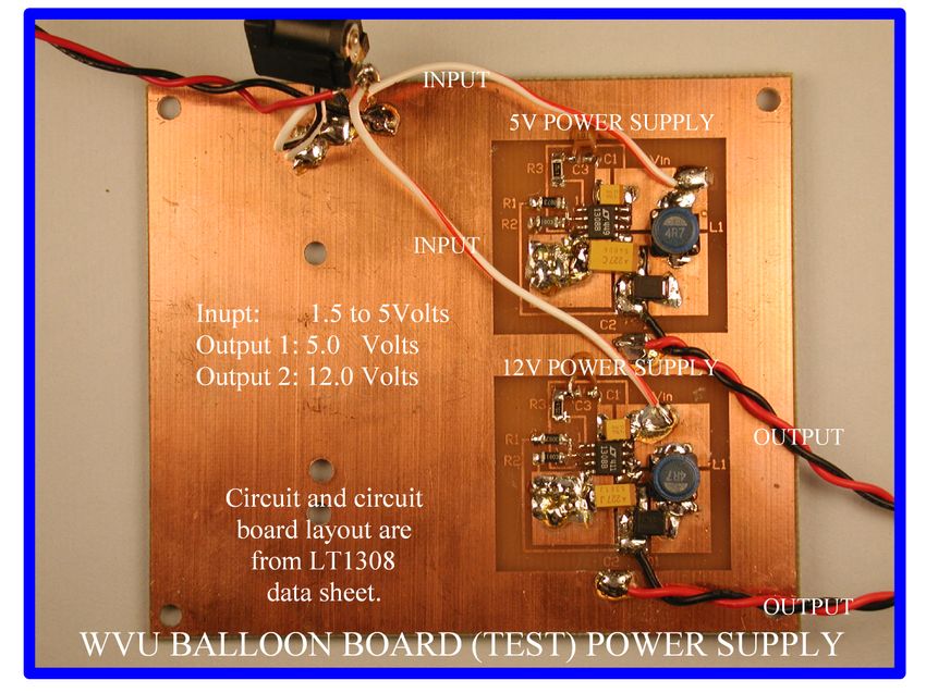
We have been bench testing step-up switching supplies based on the Linear Technology
LT1308B chip. This chip is designed to operate from a single Li-Ion cell at near 90%
efficiency. While I am always skeptical of manufactures’ specifications this one is true!
In the photo below you will see a two power supplies (one 5V and one 12V) built around
the LT1308B chips on a board designed to stack with our other boards.
I have done extensive testing of this dual power supply with an output load of 1720 mW
(5V @ 200ma plus 12V @60ma) using Lithium-Ion cells and Energizer L91 Lithium
cells. These tests were made powering both supplies from a single source. Three L91
cells in series provided a duration of 5.75 hours. We have also used Li-Ion cells scrapped
from old laptop batteries. These work very well but are somewhat heaver than the L91
cells and require charging before use.
At this time the best configuration for our current main board/GPS/radio stack is two
batteries each with three L91 cells each, one for each power supply. This should give the
3010 hour required duration. Below is a typical test curve for the Energizer L91 battery
tests.
Lithium Battery (3 AA L91cells)
(Switcher efficiency 85%)
(Load: 5V@200ma + 12v@60ma)
4000
5V (scaled)
3500 12V (scaled)
Input voltage
3000
ADC CODE (4096 = 5V)
2500
2000
1500
1000
500
0
0 60 120 180 240 300 360
Time (min.)
Using the L91 cells and the switching power supplies a savings of 250g in battery weight
plus another 50g in battery holder/hardware weight is possible. I hope to flight test this
power supply in the fall of 2005.
Other available batteries (Ni-Cd, Ni-MH, and alkaline cells) cannot deliver the sustained
high current the switchers require even though the capacity (ma-hr) is comparable to the
Li-Ion/L91 Lithium cells.
FIRMWARE/HARDWARE CHANGES
The MX614 MODEM chip may be used for both transmission and reception of AX.25
packets but is only used for transmission in the application firmware described here. I
have looked at the addition of command reception for in flight operations but as yet have
not completed the firmware to this end. Since I already have PIC firmware for this
purpose in my PIC-KISS TNC it would only be a matter of moving and integrating the
reception code into the balloon board firmware. I would like to have the ability to
“command” a sonic-alert or strobe light to help in locating the packages in the “tree
tops”. I also looked at using this command path for “cut-down” but prefer a completely
independent path for this function.
I would also like to “port” the current PIC code for the PIC16F876 to the PIC18F252
which has more code space, more data memory, expanded instruction set, “flat” memory,
faster clock speed, and the same pin-out as the as the 16F876. This may get done in the
summer of 2005.
3132
You can also read