Attachment Guide & Supplemental Increased Wind Speed Warranty Attachment Guide
←
→
Page content transcription
If your browser does not render page correctly, please read the page content below
Attachment Guide
                        &
        Supplemental Increased Wind Speed
           Warranty Attachment Guide

NOTE: The contents of this guide are considered accurate at time of posting. All
information contained within should be validated for accuracy as it relates to
specific project conditions or requirement. Specific codes, uplifts or other
factors may result in changes to the information contained within this document.
Validate all specific conditions with your Building Systems Advisor prior to its
use.

                                                                         1|Page
                               Firestone Attachment Guide
                                     January 16, 2020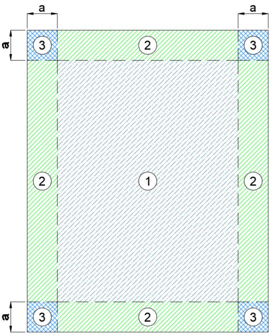
Contents
Introduction.............................................................................................................................................................................. 6
Substrate and Substrate Requirements .................................................................................................................................. 6
   General .............................................................................................................................................................................. 6
   The Minimum Fastener Pullout Resistances for Specific System ............................................................................ 7
   Criteria for Field Testing Mechanical Attachment to Various Deck Substrates ...................................................... 7
Large Wall Opening Enhancement ......................................................................................................................................... 8
Perimeter and Corner Definition – Factory Mutual (FM) ......................................................................................................... 9
   Prescriptive Enhancement Options: Perimeter and Corner..................................................................................... 10
ASCE 7 – Basic Wind Speeds for Risk/Occupancy Category .............................................................................................. 10
   ASCE 7-10 (IBC 2015/2012) ........................................................................................................................................ 10
   ASCE 7-16 (IBC 2018) .................................................................................................................................................. 10
ASCE Roof Zones ................................................................................................................................................................. 11
   ASCE 7-10 Perimeter and Corner Definition - Examples ........................................................................................ 11
   ASCE 7-16 Perimeter and Corner Definition – Examples ....................................................................................... 12
Factory Mutual Guideline - Adjoining Buildings .................................................................................................................... 15
Insulation Attachment............................................................................................................................................................ 16
       General ........................................................................................................................................................................ 16
       Attachment .................................................................................................................................................................. 16
       Multiple Layers of Insulation ..................................................................................................................................... 16
   Mechanical Attachment of Insulation to Substrate – Adhered Membrane ............................................................ 16
   Mechanical Attachment of Insulation to Substrate – Mechanically Attached Membrane ................................... 17
   Insulation Mechanical Attachment Patterns ............................................................................................................... 18
   Insulation Adhesive Attachment Pattern ..................................................................................................................... 20
       I.S.O. Twin Pack Insulation Adhesive ..................................................................................................................... 20
       I.S.O. FIX II Insulation Adhesive .............................................................................................................................. 20
       I.S.O. Stick / Winter Grade Insulation Adhesive .................................................................................................... 21
       Twin Jet Insulation Adhesive .................................................................................................................................... 21
       I.S.O. Spray R Insulation Adhesive ......................................................................................................................... 21
Criteria for Field Testing Insulation Adhesives for Adhesion to Deck Substrates................................................................. 21
   When Specified Uplifts Are Required .......................................................................................................................... 21
   Warranty Purposes with No Specified Uplift .............................................................................................................. 21
Retarders - Air and Vapor Definition ..................................................................................................................................... 22
   Vapor Retarder (Barrier)................................................................................................................................................ 22
   Air Barrier (Retarder) ..................................................................................................................................................... 23

                                                                                                                                                                            2|Page
                                                                          Firestone Attachment Guide
                                                                                January 16, 2020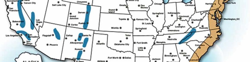
Attachment Rate Requirements for Plate Bonded Systems with an Air Barrier ................................................... 23
Modified Bitumen Base Sheet Attachment ........................................................................................................................... 25
   General ............................................................................................................................................................................ 25
   Base Sheet Attachment with any Modified Bitumen Base Sheet ........................................................................... 25
   Base Sheet Attachment with any Modified Bitumen Base Sheet ........................................................................... 26
   Base Sheet Attachment, Coiled Metal Batten, with a SBS Torch Cap .................................................................. 27
   Base Sheet Attachment, MB 2" Barbed Plates, with a SBS Torch Cap ................................................................ 27
   Base Sheet Attachment – Factory Mutual (FM) Enhancements............................................................................. 28
Single-Ply Membrane Attachment ........................................................................................................................................ 28
   Acceptable Fastener and Plate Guidelines ................................................................................................................ 28
       Table 1.05-1 ................................................................................................................................................................ 28
       Table 1.05-2 ................................................................................................................................................................ 29
       Table 1.05-3 ................................................................................................................................................................ 30
Perimeter Enhancements...................................................................................................................................................... 31
   Peel Stops ....................................................................................................................................................................... 32
Factory Mutual (FM) Attachment Layout Examples .............................................................................................................. 32
   RubberGard EPDM ........................................................................................................................................................ 32
   UltraPly TPO ................................................................................................................................................................... 33
Layouts in Chart Form – Firestone Warranty Requirements ................................................................................................ 34
   Table 1.05-4 .................................................................................................................................................................... 34
       RubberGard EPDM (Standard, LSFR, or FR), 45 or 60 mil, Batten in the Seam (BITS) ................................ 34
   Table 1.05-5 .................................................................................................................................................................... 35
       RubberGard EPDM (Standard, LSFR, or FR), 45 or 60 mil, Mechanically Attached System (MAS)............ 35
   Table 1.05-6 .................................................................................................................................................................... 35
       RubberGard EPDM MAX, 45 or 60 mil, Mechanically Attached System (MAS) .............................................. 35
   Table 1.05-7 .................................................................................................................................................................... 35
       UltraPly TPO 96, 45 mil, Mechanically Attached System (MAS) ........................................................................ 35
   Table 1.05-8 .................................................................................................................................................................... 36
       UltraPly TPO 96, 60/80 mil, Mechanically Attached System (MAS) .................................................................. 36
   Table 1.05-9 .................................................................................................................................................................... 36
       UltraPly TPO 120, 45 mil, Mechanically Attached System (MAS) ...................................................................... 36
   Table 1.05-10 .................................................................................................................................................................. 36
       UltraPly TPO 120, 60/80 mil, Mechanically Attached System (MAS) ................................................................ 36
   Table 1.05-11 .................................................................................................................................................................. 36
                                                                                                                                                                          3|Page
                                                                         Firestone Attachment Guide
                                                                               January 16, 2020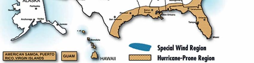
UltraPly TPO 148, 45 mil, Mechanically Attached System (MAS) ...................................................................... 36
       UltraPly TPO 148, 45 mil, Mechanically Attached System (MAS) ...................................................................... 37
   Table 1.05-12 .................................................................................................................................................................. 37
       UltraPly TPO 148, 60/80 mil, Mechanically Attached System (MAS) ................................................................ 37
   Table 1.05-13 .................................................................................................................................................................. 37
       Firestone PVC 120, 50 mil, Mechanically Attached System (MAS) ................................................................... 37
   Table 1.05-14 .................................................................................................................................................................. 37
       Firestone PVC 120, 60/80 mil, Mechanically Attached System (MAS).............................................................. 37
   Table 1.05-15 .................................................................................................................................................................. 37
       Firestone PVC XR 120, 60/80 mil, Mechanically Attached System (MAS) ....................................................... 37
InvisiWeld Attachment........................................................................................................................................................... 38
   General ............................................................................................................................................................................ 38
   Induction welded membrane: ....................................................................................................................................... 38
   Heat welded membrane seams: .................................................................................................................................. 38
   Invisiweld Fastener Patterns: ....................................................................................................................................... 38
   Invisiweld Warranty Requirements: ............................................................................................................................. 41
   Invisiweld Enhancement Requirements: .................................................................................................................... 42
   Factory Mutual (FM) Invisiweld Attachment Rates ................................................................................................... 43
   Metal Building Re-Cover (MBR) – Invisiweld Attachment Rates – Standard Warranty ...................................... 43
Metal Building Re-Cover – Mechanically Attached FM Enhancement Options – ................................................................. 44
Factory Mutual Loss Prevention Data Sheet 1-31 – 3.1.4.1 ................................................................................................. 44
Standing Seam Roof (SSR) Factory Mutual (FM) Inseam Enhancement Options ............................................................... 45
References ............................................................................................................................................................................ 45
   Factory Mutual (FM)....................................................................................................................................................... 45
   Underwriters Laboratories (UL) .................................................................................................................................... 45
   American Society of Civil Engineers & Structural Engineering Institute (ASCE/SEI) .......................................... 45
Firestone Increased Wind Speed Warranty Minimum Attachment Rate Guide.................................................................... 47
   Alaska, Hawaii and International Projects .................................................................................................................. 47
   Metal Roofing .................................................................................................................................................................. 47
   Asphalt/Mod-Bit Roofing................................................................................................................................................ 47
   General Notes ................................................................................................................................................................. 48
   Edge Metal Requirements ............................................................................................................................................ 48
   Hurricane-Prone Regions and Special Wind Regions .............................................................................................. 49
Increased Wind Speed Warranty Attachment Requirements ............................................................................................... 50

                                                                                                                                                                          4|Page
                                                                         Firestone Attachment Guide
                                                                               January 16, 2020
Cover Board/Insulation Attachment Rates - Adhered Single-Ply Membrane Roofing Systems ........................ 50
       Additional Notes: ........................................................................................................................................................ 51
Half Sheet Information .......................................................................................................................................................... 52
   Warranty .......................................................................................................................................................................... 52
UltraPly TPO Mechanically Attached or Adhered Membrane Options ................................................................................. 52
   Increased Wind Speed System Options ..................................................................................................................... 52
UltraPly TPO Membrane – Mechanically Attached Requirements ....................................................................................... 53
   TPO - Steel/Concrete - 22 ga Steel Deck or 3,000 psi Structural Concrete Decks ............................................. 53
   TPO - Wood Decks ........................................................................................................................................................ 54
   TPO - LWC over Steel/Structural Concrete - UltraPly TPO Membrane Mechanically Attached into Min. 22 ga
   Steel Pan/Deck or 3,000 psi Structural Concrete ...................................................................................................... 55
   TPO - Invisiweld Attachment Requirements .............................................................................................................. 55
Firestone PVC Mechanically Attached or Adhered Membrane Options ............................................................................... 56
   Increased Wind Speed System Options ..................................................................................................................... 56
Firestone PVC Membrane – Mechanically Attached Requirements ..................................................................................... 56
   PVC - Steel/Concrete - 22 ga Steel Deck or 3,000 psi Structural Concrete Decks ............................................. 56
   PVC - Wood Decks ........................................................................................................................................................ 57
   PVC - LWC over Steel/Structural Concrete - UltraPly TPO Membrane Mechanically Attached into Min. 22 ga
   Steel Pan/Deck or 3,000 psi Structural Concrete ...................................................................................................... 58
   PVC - Invisiweld Attachment Requirements .............................................................................................................. 58
RubberGard™ MAX EPDM Mechanically Attached or Adhered Membrane Options........................................................... 59
   Increased Wind Speed System Options ..................................................................................................................... 59
RubberGard MAX EPDM Membrane – Mechanically Attached Requirements .................................................................... 59
   EPDM - Steel/Concrete - 22 ga Steel Deck or 3,000 psi Structural Concrete Decks.......................................... 59
   EPDM - Wood Decks ..................................................................................................................................................... 60
   EPDM - LWC over Steel/Structural Concrete - RubberGard EPDM Membrane Mechanically Attached into
   min. 22 ga Steel Pan/Deck or 3,000 psi Structural Concrete .................................................................................. 61
Base Sheets – Mechanical Attachment Requirements ......................................................................................................... 61
   LWC - Base Sheet attachment rates– Minimum pull out values ............................................................................. 61

                                                                                                                                                                         5|Page
                                                                        Firestone Attachment Guide
                                                                              January 16, 2020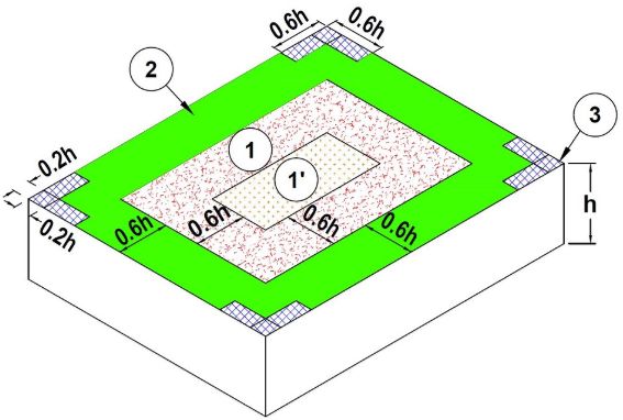
Introduction
The purpose of this guide is to reinforce installation techniques. The following guide is a supplement to be used in conjunction with the
other technical information located on the Firestone Building Products website. Reference to the specific Design Guide, Quick
Specifications, Application Guide, Details, Technical Information Sheets (TIS), and other Specifications is necessary to ensure that the
finished roof system is installed in compliance with Firestone requirements.
The following document outlines the required attachment rates and conditions that Firestone Building Products looks for to issue a
warranty. When the project requires specific codes and/or uplifts to be met the attachment rates below may not be appropriate. Review
of the specific project conditions and specifications should be completed and all pertinent information must be provided to Firestone
Building Products prior to the project being bid or installed. Failure to do so may result in required changes to the bids, products used,
installation and/or possible denial of warranty coverage. Not all conditions are covered in this document. Please contact your Firestone
Sales Representative or your Regional Building System Advisor for conditions or information not found in this document.
Due to unknown variables associated with each building structure, Firestone suggests a licensed engineer to verify all
attachment rates are appropriate for the specific project requirements. It is the responsibility of the Architect, Design
Professional, Engineer and/or Building Owner to verify that the installed roofing system and related components are installed
to meet the specified requirements of the International Building Code, State and Local codes and other related requirements.
It is the responsibility of the specifier to review local, state and regional codes to determine their impact on the specified system.
Drainage must be evaluated by the specifier in accordance with all applicable codes. For code compliance, increased fastening
density may be required depending upon project wind speed and wind uplift requirement. Subject to code requirement, it is
recommended that a minimum roof slope of 1/8" per horizontal foot be provided to serve long-term aesthetics.
NOTE: IF A PROPOSED APPLICATION FALLS OUTSIDE OF THIS SPECIFICATION, CONTACT YOUR BUILDING SYSTEMS
ADVISOR FOR ADDITIONAL INFORMATION.
Within Firestone Specifications, reference is made to Firestone’s Mechanically Attached Systems.
Mechanically Attached Systems include:
Batten in The Seam – BITS
Batten Bar or plates in the seam of the membrane.
Plates are only allowed with reinforced membranes
Mechanically Anchored System (Non-Reinforced Membrane) – MAS
Lay out sheet battens on membrane, strip in
Mechanically Anchored System (Reinforced Membrane) - Reinforced MAS
Lay out sheet, set plates or battens on membrane, strip in
Reinforced Mechanically Attached Strip – RMA
Lay out strips over insulation; attach strip using plate or battens, place membrane over the strips.
Substrate and Substrate Requirements
General
1. The Firestone roof system depends on a suitable substrate to perform its intended function of weatherproofing the
building.
It is the roofing contractor’s responsibility for ensuring that the substrate is acceptable for the Firestone roof system.
2. The substrate to which the Firestone roof system is installed must:
Be structurally sound
Be dry, smooth, flat and clean
Be free of sharp fins, or foreign materials that could damage the membrane
Meet the minimum requirements for the system
3. When using asphalt to adhere to insulation to a structural concrete substrate, the concrete must be primed with an ASTM
D 41 asphalt primer. The primer is applied at a rate of 1½ to 2 gallons per 100 ft² (0.61 to 0.82 L/m²). Proper flashing off
times should be considered in all adhesive applications.
4. Acceptable substrates include but may not be limited to:
22-gauge steel decking, minimum 33 ksi
Structural Concrete, minimum 3000 psi
Wood – Plank minimum ¾", Plywood minimum 15/32" or OSB minimum 7/16" thickness
Cementitious Wood Fiber, minimum 2" thick
Gypsum, minimum 2" thick
Light Weight Insulation Concrete over Steel Pan or Structural Concrete, minimum 2" thick
6|Page
Firestone Attachment Guide
January 16, 2020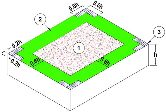
The Minimum Fastener Pullout Resistances for Specific System
The information listed in the chart below is for use with the referenced roof deck, fastener type, minimum pullout values and required
penetration depths based on fasteners type. These values are in reference to mechanically attached insulation/cover boards under
adhered membranes or mechanically attached membrane assemblies. If a listed value cannot be met please contact your Building
Systems Advisor to discuss. The information below is valid for Firestone Red Shield Warranties up to 20 years. Contact your Building
Systems Advisor for requirements on specific conditions or longer warranty terms.

                                                                                                                     Minimum
       Deck Type                        Minimum Pullout (3)                             Fastener
                                                                                                                    Penetration
          Steel,             Attached Insulation       300 lb (136.1 Kg)           All Purpose (AP)                ¾" through deck
      min. 22 gauge                                                                Heavy Duty (HD)                 ¾" through deck
      or heavier (2)        Attached Membrane          400 lb (181.4 Kg)             AccuTrac Kit                  ¾" through deck
                                                                                       #12 Belted                  ¾" through deck
                             Attached Insulation       300 lb (136.1 Kg)               #15 Belted                  ¾" through deck
     Steel, less than                                                                   HailGard                   ¾" through deck
      22 gauge (1)(2)       Attached Membrane                N/A                 Heavy Duty Plus (HD+)             1" through deck

   Structural Concrete                                                              Heavy Duty (HD)
                             Attached Insulation       300 lb (136.1 Kg)                                           1" into the deck
   3,000 psi or greater                                                                HailGard
        (min. 2")           Attached Membrane          400 lb (181.4 Kg)             Concrete Drive               1¼" into the deck
       Wood Plank,          Attached Insulation        300 lb (136.1 Kg)            All Purpose (AP)
       ¾" minimum           Attached Membrane          400 lb (181.4 Kg)            Heavy Duty (HD)
     Oriented Strand        Attached Insulation        300 lb (136.1 Kg)              AccuTrac Kit
      Board (OSB),                                                                      #12 Belted             1" into or through deck
     min. 7/16" thick       Attached Membrane          400 lb (181.4 Kg)                #15 Belted
        Plywood,            Attached Insulation        300 lb (136.1 Kg)                Nail Driver
     min. 15/32" thick      Attached Membrane          400 lb (181.4 Kg)                 HailGard

  Lightweight Insulating    Attached Insulation        300 lb (136.1 Kg)            Heavy Duty (HD)
                                                                                                                   ¾" through pan
        Concrete            Attached Membrane          400 lb (181.4 Kg)               HailGard
     over Steel Pan          Nailed Base Sheet          40 lb (18.1 Kg)       1.7" LWC Base Ply Fastener*         Base Sheets Only
                                                                                    Heavy Duty (HD)
  Lightweight Insulating     Attached Insulation       300 lb (136.1 Kg)                                        1" into Concrete Deck
                                                                                       HailGard
        Concrete
                            Attached Membrane          400 lb (181.4 Kg)             Concrete Drive            1¼" into Concrete Deck
      over Concrete
                             Nailed Base Sheet          40 lb (18.1 Kg)       1.7" LWC Base Ply Fastener*        Base Sheets Only
                            Attached Insulation        300 lb (136.1 Kg)
         Gypsum,                                                                    Polymer Fastener                1½" into deck
                            Attached Membrane                 N/A
     minimum 2" thick
                             Nailed Base Sheet          40 lb (18.1 Kg)       1.2" LWC Base Ply Fastener*         Base Sheets Only
  Tectum, Cementitious      Attached Insulation        300 lb (136.1 Kg)
                                                                                     Polymer Fastener             1½" into deck
        Wood Fiber,         Attached Membrane                 N/A
     minimum 2" thick        Nailed Base Sheet          40 lb (18.1 Kg)        1.2" LWC Base Ply Fastener*     Base Sheets Only
        Base Sheet
                                                                                       See approved               See approved
   Attached to Deck with                         300 lb
                                                                                     fasteners above.             depths above.
   Plates and Fasteners
*For the attachment of base sheets only. Insulation may not be attached with the LWC Base Ply Fasteners
NOTE:
 1. Steel Decks 22 gauge or less may require additional fastening enhancements if min. pull values cannot be met.
 2. Mechanically Attached Systems are not approved over corrugated steel decking.
 3. Systems using Invisiweld Plates will require the fasteners to achieve a minimum of 400 lb pull resistance.
 4. When Oriented Strand Board (OSB) is to be used the smooth side of the board should be facing up.

Criteria for Field Testing Mechanical Attachment to Various Deck Substrates
Fastener pull tests should be performed in accordance to the requirements listed within ANSI/SPRI FX-1, Standard Field Test Procedure
for Determining the Withdrawal Resistance of Roofing Fasteners. All pull tests should be documented via Pullout Test Report and
provided to Firestone. Official pullout results may impact the required fastening rates for the project.

                                                                                                                            7|Page
                                                     Firestone Attachment Guide
                                                           January 16, 2020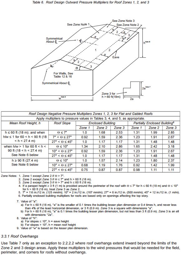
Large Wall Opening Enhancement
ASCE 7 should be consulted to determine the appropriate building configuration, enclosed, partially enclosed or open. The building
configuration impacts the appropriate design and attachment required for the roofing system. If an existing building is altered, adding
large openings, change of use, etc., adjustments may need to be made to accommodate the changes.

The large wall opening enhancement is required when the sum of the various opening areas (w x h) is greater than 10% of the wall area.

Perimeter ½ sheets are required in the hatched area as shown in the diagram below. It is common installation practice to extend the
perimeter along this entire building plan dimension to accommodate this rule, but it not required. For warranty purposes Firestone finds
it acceptable to utilize battens, plates and fasteners or Invisiweld attachment methods for this enhancement.

                                                               1.5
                                                                   xW
                                                               CL
                                        W
                                   2x

                                   CL

                                                                                                1.5
                                                                                                    xW
                                                                                                CL
                                                                         W
                                                                    2x

                                            H                       CL
                               W

                                                                             H
                                                                W

                                                                                                                            8|Page
                                                     Firestone Attachment Guide
                                                           January 16, 2020
Perimeter and Corner Definition – Factory Mutual (FM)
The following diagram is direct form the FM Global Property Lost Prevention Data Sheet 1-28.
This outlines how to calculate your perimeter and corner areas based on the building size and relative conditions.

                                          ©2015 Factory Mutual Insurance Company. All rights reserved.

                                                                                                                     9|Page
                                                       Firestone Attachment Guide
                                                             January 16, 2020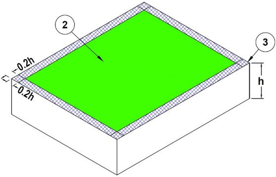
Prescriptive Enhancement Options: Perimeter and Corner
The following information has been referenced from Factory Mutual Loss Prevention Data Sheets 1-29.

2.2.10.1.1 Provide one of the following options to secure the roof perimeter and corners (Zones 2 and 3):
     A. Use a roof system with an FM Approval wind uplift rating that is acceptable for the field, perimeter, and corners per the Ratings
         Calculator of RoofNav or DS 1-28. That could entail using a system throughout the entire roof that had a wind rating adequate
         for the corners, or using a system that has a varied fastener spacing and multiple wind ratings that are adequate for the field,
         perimeter, and corner areas.
     B. Use the appropriate prescriptive recommendation noted in FM LPDS 1-29 Section 2.2.10.1.2.

In either case, ensure any whole or partial insulation board or roof cover/base sheet width (when the roll is parallel to the building edge)
that falls within the calculated perimeter or corner has the increased securement applied over the entire board or roof cover/base sheet
width.

2.2.10.1.2 Use prescriptive enhancements for perimeter and corner areas (for all deck types) where roof covers are adhered to some
combination of insulation or cover board if one of the following conditions applies:
     A. The recommended field-of-roof rating needed per DS 1-28 in any location does not exceed Class 1-75 (3.6 kPa),
     B. The building is in a non-hurricane-prone region (see Appendix A) and the recommended field-of-roof rating per DS 1-28 does
         not exceed Class 1-90 (4.3 kPa).

2.2.10.1.2.1 For either of the above conditions, increase the securement over the FM Approved field-of-roof spacing as follows:
     A. For assemblies using insulation fasteners, increase the number of fasteners per board by:
         1. 50% minimum in the roof perimeter, but at least one fastener per 2 ft² (1 per 0.19 m²). It is not necessary to install fasteners
              closer than one per 1 ft² (1 per 0.09 m²).
         2. One fastener per 1 ft² (1 per 0.09 m²) in corner areas.
         3. Round up to the next whole number of fasteners, if necessary
     B. For components adhered with adhesives applied in ribbons, spots, etc., reduce the spacing between ribbons or spots over the
         FM Approved spacing for the given wind rating as noted below (round down to a dimension that is practical with respect to board
         sizes, applicators, etc.):
         1. In the roof perimeter, not more than 60% of the field-of-roof spacing between rows, or area Roof Deck Securement and
              Above-Deck Roof Components 1-29 FM Global Property Loss Prevention Data Sheets Page 21 ©2016 Factory Mutual
              Insurance Company. All rights reserved.
         2. In the roof corners, not more than 40% of the field-of-roof spacing between rows, or area

ASCE 7 – Basic Wind Speeds for Risk/Occupancy Category
The American Society of Civil Engineers (ASCE) provides basic wind speed maps based on Occupancy/Risk Category of buildings.
Refer to the appropriate version of the ASCE for wind maps specifc to the the buildings occupancy category. These maps can be found
in the specific editions of the ASCE and can be found at www.atcouncil.org/windspeed. Locations that fall within a special wind region
should be reviewed by an engieer to validate the full scope of the projects requirements.

ASCE 7-10 (IBC 2015/2012)
ASCE 7-10 offers basic wind speed maps for occupancy categories I, II, III and IV. In this edition of the ASCE Occupancy Category III
and IV are combined on the same map, while category I and II have their own maps. In this edition three maps are provided based on
Occupancy/Risk Category. This version of the ASCE uses a more generalized approach to the areas of the county where most of the
county falls within one wind speed and the coastal areas are more defined with contour lines and varying wind speeds.

ASCE 7-16 (IBC 2018)
ASCE 7-16 offers basic wind speed maps for occupancy categories I, II, III and IV. In this edition of the ASCE all Occupancy/Risk
Categories have been defined on their own maps. In this edition four maps are provided based on Occupancy/Risk Category. This
version of the ASCE uses more detailed contour lines throughout the map showing more accurate wind speed estimates.

                                                                                                                              10 | P a g e
                                                       Firestone Attachment Guide
                                                             January 16, 2020
ASCE Roof Zones
ASCE 7-10 Perimeter and Corner Definition - Examples
The diagram below is an example only. Each building type and shape may require its own specific layout for perimeters and corners.
ASCE 7-10 should be consulted for nonstandard building/roof types and shapes.
h ≤ 60 ft.
Notation:
a = 10 percent of least horizontal dimension or 0.4h, whichever is smaller,
but not less than either 4% of least horizontal dimension or 3 ft (0.9 m).
h = Eave height shall be used for θ ≤ 10°.
θ = Angle of plane of roof from horizontal, in degrees.
h > 60 ft.
Notation:
a = 10 percent of least horizontal dimension, but not less than 3 ft (0.9 m).
h = Eave height shall be used for θ ≤ 10°.
θ = Angle of plane of roof from horizontal, in degrees.
11 | P a g e
Firestone Attachment Guide
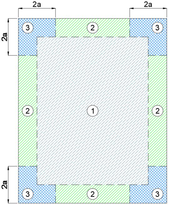
January 16, 2020ASCE 7-16 Perimeter and Corner Definition – Examples
Data referenced from ASCE/SEI 7-16 Minimum Design Loads and Associated Criteria for Buildings and Other Structures. All referenced
information should be validated against the current document and local relevant building codes. Roof zones may change based on actual
building size/layout and roof type. See ASCE documents to validate zones based on building conditions.
6h
0.
6h
2a
2a
0. 2
3
2 2
3
1
h h
0.
1
2h
1'
0.
6h
0.
a
6h
2
6h
0.
2
6h
0.
a
2h
0.
Roof Zone Layout for Enclosed, Partially Enclosed Buildings Roof Zone Layout for Enclosed, Partially Enclosed Buildings
(Referenced from ASCE 7-16 Figure 30.4-1) (Referenced from ASCE 7-16 Figure 30.5-1)
Zones Example: Building Height = 30' Zones Example: Building Height = 75'
Building Height = 60 ft (1') Field Prime = Remainder Building Height > 60 ft Flat/Hip/Gable (0° = T = 7°)
Flat/Hip/Gable (0° = T = 7°) (1) Field = 18'-0" wide Roof Area = 80' x 150' (1) Field = Remainder
(2) Perimeter = 18'-0" wide a = 10% of least horizontal dimension, (2) Perimeter = 8'-0" wide
(3) Corners = "L" Shape 18'x18'x6' but not less than 3 ft. (0.9m) (3) Corners = "L" Shape 16'x16'x8'
12 | P a g e
Firestone Attachment Guide
January 16, 2020ASCE 7-16 - Potential Zone Layouts Based on Building Ratio Scenario
13 | P a g e
Firestone Attachment Guide
January 16, 2020When the greatest horizontal dimension is less than 0.4h, the whole roof area is considered Zone 3.
14 | P a g e
Firestone Attachment Guide
January 16, 2020Factory Mutual Guideline - Adjoining Buildings
Data referenced from Factory Mutual (FM) Loss Prevention Data Sheet (LPDS) 1-28.
This information is applicable to FM standards only.
When a building adjoins another, and has an elevation change of less than 10′ then the perimeter and corner enhancements can be
omitted in that area. See the diagram below for an example.
When a building adjoins another, and has an elevation change greater than or equal to 10′ then the higher roofing area requires a
standard building layout (perimeter and corner enhancements). The lower roof area can still omit the perimeter and corner enhancements
in that area. See the diagram below for an example.
If there are concerns regarding this enhancement, contact your Building Systems Advisor at 800-428-4511 for further clarification.
15 | P a g e
Firestone Attachment Guide
January 16, 2020Insulation Attachment
General
1. Insulation must provide a suitable substrate for the proposed roof system as well as insulation for the building.
2. Insulation thickness requirements may vary for code compliance. Contact the local code or insurance official before
contacting your Building Systems Advisor at 1-800-428-4511.
3. Refer to Insulation Technical Information Sheet (TIS) for specific spanning capabilities.
Attachment
1. Insulation may be installed by various methods including fasteners, adhesives and asphalt. It is acceptable to combine
fastener and adhesive attachment methods in multi-layer applications.
2. Tapered insulation below the 1" (25.4 mm) minimum thickness must be fastened at a rate of one (1) fastener and plate per
two (2) ft² (0.22 sq. m). If possible, install the tapered insulation first, covered by the flat stock.
3. Refer to specific Firestone Technical Information Sheets (TIS) for installation and fastening requirements.
4. When a composite of two insulation layers is installed, the fastening pattern required for the top board thickness must be
used. A common fastener may be used to install multilayer applications. Some restrictions apply to fastener length
depending on standards used.
Multiple Layers of Insulation
1. Where overall insulation thickness is 2" (50.8 mm) or greater, Firestone recommends installing the insulation in two (2) or
more layers.
2. Insulation may be installed in one or multiple layer applications for the Firestone warranty. If installed in multiple layers, the
joints of each succeeding and adjoining layer should be staggered from the joints of previous layers by a minimum of 6"
(152.4 mm) in each direction. When a composite of two insulation layers is installed, the fastening pattern required is
dependent on the top board type and thickness. A common fastener may be used to simultaneously fasten all layers to the
structural deck.
Mechanical Attachment of Insulation to Substrate – Adhered Membrane
Insulation/Substrate Attachment
Red Shield
Thickness Insulation Min. # of Fasteners per Adhesive Ribbon
Warranty
4' x 8' boards Spacing 4' x 4' boards
¼ʺ 16
½" DensDeck® 12
⅝" 8
¼ʺ 12
½" DensDeck® Prime 10
⅝" 8
¼ʺ 10
½" Securock® 8
55 mph ⅝" 8 F12 – P6 – C6
½" ISOGARD HD 12
½" – 1.4" ISOGARD GL/ 16
1.5" – 1.9" ISO 95+ GL/ 12
≥ 2ʺ Resista/ISOGARD CG 8
1.5" ISOGARD HD 12
2ʺ Composite 8
1.5" 8
HailGard/ISOGARD HG
2ʺ 12
16 | P a g e
Firestone Attachment Guide
January 16, 2020Mechanical Attachment of Insulation to Substrate – Mechanically Attached Membrane
1. Insulation must be fastened with appropriate Firestone fasteners and insulation plates.
2. Firestone All Purpose (AP’s) fasteners are not acceptable, except for wood decks, for any 25 years, 20-year systems (membrane
attachment), 15-year re-cover, re-roof or partial tear off applications.
3. 30-year systems require the use of Heavy-Duty, Heavy-Duty Plus, Concrete Drive or Polymer Fasteners for insulation and membrane
attachments.
4. Fastening rates and patterns may vary for code or regulatory compliance. Contact local code or insurance official before contacting
your Building Systems Advisor at 800-428-4511.
Table 1.02-1
*Rates in this table may differ from tested assemblies. In such case the more stringent rate should be used.
*Rates in this table refer to minimum warranty requirements for a standard Firestone Red Shield 20 Year Warranty unless noted.
Fastening Patterns for Insulation in Mechanically Attached Single Ply Systems*
Top Layer of Insulation Number of Fasteners per Insulation Board
Maximum No Air Retarder With an Air Retarder*
Warranty 4' x 4' 4' x 8' 4' x 4' 4' x 8'
Term Insulation Thickness
Insulation Insulation Insulation Insulation
Board Board Board Board
ISOGARD GL/ 1.0" - 1.4" 4 5 8 16
ISO 95+ GL or 1.5" - 1.9" 4 5 6 12
Resista/
ISOGARD CG 2.0" - 4" 4 5 4 8
Dens Deck/ ¼" 4 5 8 16
Up to 25-Year Dens Deck Prime ½" 4 5 6 12
Securock ⅝" 4 5 4 8
HailGard/
1.5" min. 4 5 8 16
ISOGARD HG
ISOGard HD ½" 4 5 6 12
ISOGard HD Comp. 1" min. 4 5 8 16
Up to 15-Year Structodek ½" - 1" 4 5 8 16
* The use of an Air Retarder requires that the cover board/insulation presecurement be increased to accommodate the added uplift the
system may experience due to the retarder. Proper application details for the air retarder should be followed.
17 | P a g e
Firestone Attachment Guide
January 16, 2020Insulation Mechanical Attachment Patterns
The diagrams below show the required patterns for proper placement of approved fasteners and plates for insulation. These fastening
patterns apply to standard 4' x 8' boards. The most common fastener density and patterns are shown. Certain specifications may call
for increased densities of fasteners in the perimeter or corner areas. For these patterns and other non-standard fastener densities,
contact your Building Systems Advisor at 800-428-4511.
96" 96"
12" 24" 12" 6" 36" 6"
6"
12"
24"
48" 24" 48" 36"
24"
Eight (8) Ten (10)
96" 96"
6" 36" 6" 12" 18" 18" 18" 18" 12"
6" 6"
24"
18"
48" 36" 48"
12" 24"
18"
6"
Twelve (12) Fifteen (15)
96" 96"
6" 18" 18" 6" 6" 18" 18" 6"
6" 6"
12" 12"
12"
18" 18"
12" 24" 12"
48" 48"
12"
18" 18"
6" 6"
Sixteen (16) Eighteen (18)
96" 96"
6" 12" 12" 12" 6" 6" 12" 12" 12" 6"
6" 6"
12"
18" 18"
12" 12" 12" 12"
48" 24" 48"
18" 18"
6" 6"
Twenty (20) Twenty-Three (23)
18 | P a g e
Firestone Attachment Guide
January 16, 202096" 96"
6" 18" 18" 6" 12" 12" 12" 12"
6" 6"
12"
18"
18" 12" 18" 12"
18"
12"
48" 12" 48" 12"
12"
18"
12"
12"
6" 6"
Twenty-Four (24) Twenty-Seven (27)
96" 96"
6" 12" 12" 12" 6" 6" 12" 12" 12" 6"
6" 6"
12" 12" 12" 12" 12" 12"
48" 12" 48" 12"
12" 12"
6" 6"
Thirty (30) Thirty-Two (32)
19 | P a g e
Firestone Attachment Guide
January 16, 2020Insulation Adhesive Attachment Pattern
The following Firestone Insulation Adhesives and application methods are acceptable:
Firestone Insulation Adhesive Application Method
I.S.O. Twin Pack Bead applied
I.S.O. FIX II Bead applied
I.S.O.Stick / Twin Jet Bead applied
I.S.O. Spray R Bead applied or Spray applied
The maximum size of any insulation board is 4' (1.2 mm) x 4' (1.2 mm) regardless of the thickness. The rate of application, with a
Firestone Insulation Adhesive, is four (4) ribbons per board to be installed in ½" to ¾" beads spaced 12" on center for a standard 55 mph
Red Shield warranty. The adhesive application does not increase or decrease with the thickness of the board as in mechanically fastened
insulation boards. Loose or unattached corners in insulation boards shall be repaired by the addition of fasteners and insulation plates
as required.
Refer to the Technical Information Sheet for specific information on these products: Foam Adhesives. If enhancements are required or
your project presents a unique situation, contact your Building Systems Advisor at 800-428-4511.
Board Edge 48" Adhesive Board Edge 48" Adhesive
6" 6"
12" 12"
48" 12" 48" 12"
12" 12"
6" 6"
Ribbon Pattern Serpentine Pattern
I.S.O. Twin Pack Insulation Adhesive
Ensure the use of a 4' x 4' board.
Application surfaces must be even to ensure continuous adhesion.
Immediately place insulation board into wet adhesive.
The first and last adhesive bead should be inset 6" from the board edge for a 12" o.c. application, inset 3" o.c. or 6" o.c. application
and inset 2" o.c. for 4" o.c. application.
Immediately place insulation board into wet adhesive and weight with pails of Bonding Adhesive or other viable weight.
See ribbon pattern diagram above.
I.S.O. FIX II Insulation Adhesive
Ensure the use of a 4' x 4' board.
Application surfaces must be even to ensure continuous adhesion.
Immediately place insulation board into wet adhesive and weight with pails of Bonding Adhesive or other available weight.
The first and last adhesive bead should be inset 6" from the board edge for a 12" o.c. application, inset 3" o.c. for 6" o.c.
application and inset 2" o.c. for 4" o.c. application.
See serpentine style pattern above.
20 | P a g e
Firestone Attachment Guide
January 16, 2020I.S.O. Stick / Winter Grade Insulation Adhesive
Ensure the use of a 4' x 4' board.
Requires the PaceCart 2 Dispenser
Application surfaces must be even to ensure continuous adhesion.
Place board while adhesive is still wet and tacky. Adhesive should not reach a tack-free state.
The first and last adhesive bead should be inset 6" from the board edge for a 12" o.c. application, inset 3" o.c. for 6" o.c.
application and inset 2" o.c. for 4" o.c. application.
Wait for the adhesive to develop a stringy body before placing the insulation board into the adhesive. Immediately walk the board
in and weight it down with pails of Bonding Adhesive or other available weight.
See serpentine style pattern above.
Twin Jet Insulation Adhesive
Ensure the use of a 4' x 4' board.
Apply Twin Jet on the deck substrate in 1¼ʺ beads spaced 12ʺ (300 mm) on center, or as specified to meet wind uplift requirements.
Allow adhesive to reach the open/mate time and set the suitable insulation into position.
Place maximum 4' x 4' (1.22 m x 1.22 m) insulation boards into Twin Jet Insulation Adhesive within the identified mate time.
Immediately after setting the insulation board, provide continuous pressure using weighty objects such as adhesive pails on the
insulation until the adhesive sets (typically 4-8 minutes) to ensure adequate contact between the insulation, substrate and adhesive
during the critical set-up period.
I.S.O. Spray R Insulation Adhesive
Ensure the use of a 4' x 4' board.
Performance of I.S.O. SPRAY R Adhesive should be periodically monitored during the workday to verify that sufficient rise, adhesion,
and full mating is occurring.
Requires spray rig equipment to apply.
Application surfaces must be even to ensure continuous adhesion.
Immediately place insulation board into wet adhesive.
The first and last adhesive bead should be inset 6" from the board edge for a 12" o.c. application, inset 3" o.c. for 6" o.c. application
and inset 2" o.c. for 4" o.c. application.
Wait for the adhesive to develop a stringy body before placing the insulation board into the adhesive. Immediately walk the board
in and weight it down with pails of Bonding Adhesive or other available weight.
See serpentine style pattern above.
Criteria for Field Testing Insulation Adhesives for Adhesion to Deck Substrates
When Specified Uplifts Are Required
Adhesive pull tests should be performed in accordance to the requirements listed within ANSI/SPRI IA-1, Standard Field Test Procedure
for Determining the Uplift Resistance of Insulation and Insulation Adhesive Combinations over Various Substrates.
All adhesive pull tests should be documented via Insulation Adhesive Test Report and provided to Firestone.
Official pullout/adhesion results may impact the required fastening rates for the project.
Warranty Purposes with No Specified Uplift
1. Prepare an area large enough to allow a 4' x 4' insulation board to be laid in place. Follow the appropriate Firestone Technical
Information Sheet guidelines for surface preparation and list of acceptable substrates. Contact your Building Systems Advisor at
800-428-4511 if the substrate information is not listed.
2. Apply the adhesive to the deck per recommended application rates and methods (12" o.c., ½" to ¾" bead).
3. Allow the adhesive a minimum of 60 minutes to cure.
4. After the adhesive has been allowed to cure, pull up on the adhered board by placing a hand under the corner or end of the board
in the same direction as the ribbons. Make sure that the board is lifted by hand. Using tools to scrape the board may cause
disbonding between the adhesive and the substrate. This will not show whether the adhesive is performing under uplift
considerations. (If a tool is used, it should be used to pry or pop the board up).
5. Observe the insulation and deck. The desired result is a delamination of the surface or board facer with adhesive and facer residue
remaining on the deck or the board breaks apart remaining adhered to the deck at the ribbons. If the board is lifted and the
adhesive pulls/peels off the deck or decking is pulled up with the board, contact your Building Systems Advisor. This will
be considered an unacceptable substrate.
6. Results should be documented via photos, location on roof and number of tests performed and provided to your Firestone Building
Systems Advisor for approval. Results from the testing may impact the required fastening/adhesive rates required for the project.
21 | P a g e
Firestone Attachment Guide
January 16, 2020Retarders - Air and Vapor Definition
Vapor/air retarders provide protection to the above deck components from air infiltration and condensation due to high internal moisture
loads. Moisture sealed into the roof system during construction may expand during hot weather, causing blisters to form in the roof
covering and eventually leading to failure of the roof system. Vapor retarders prevent moisture from infiltrating to the above deck
components. Air retarders prevent air from infiltrating to the above deck components. A vapor/air retarder for steel, wood or concrete
deck may be provided in the form of a membrane sheet applied over the deck surface. The membrane sheet or film type of vapor/air
retarder may be supplied as asphalt-saturated felt, vinyl plastic, Kraft paper, etc., or a laminated combination.
FM Approved vapor/air retarder sheets shall be placed directly on the deck or over a minimum FM Approved thickness of insulation or
separator board. They shall be installed in accordance with the Approval requirements. Then, FM Approved insulation is placed and
fasteners driven through the components into the deck.
When an air retarder or vapor retarder is listed as a component with a mechanically fastened roof cover, it is imperative that the air/vapor
retarders restrict air infiltration to the roof assembly between the top of the air retarder and the underside or the roof covering. To
accomplish this, the air/vapor retarder must encapsulate these roof components. An accepted means of encapsulating these components
is to fold the air/vapor retarder up along the edges of the components and seal the air/vapor retarder to the underside or the roof covering
using a compatible adhesive. The encapsulating must be done at the entire roof perimeter and at all roof penetrations. Additionally, if the
integrity of the air/vapor retarder is breached; e.g., equipment is added on the roof, the air/vapor retarder must be sealed to the underside
of the roof cover using a compatible adhesive.
FM Approved vapor/air retarders have been evaluated for fire hazard and/or wind resistance only, not for permeability. See additional
information below as it relates specifically to Vapor or Air retarders.
Vapor Retarder (Barrier)
For adhered above-roof covers, when insulation is adhered to the top surface of a vapor retarder, the vapor retarder is part of the wind
load path and, as such, its strength and securement are critical. When roof covers are adhered to insulation or cover boards that are
fastened through the vapor retarder into the deck, the wind load applied to the roof cover by-passes the vapor retarder. Vapor Retarders
are materials designed to restrict passage of water vapor located on the “warm side” of the roof or sandwiched between insulation layers.
The vapor retarder is sealed to the exterior walls of the building, but not necessarily to the underside of the roof cover. While some
Firestone roofing systems may require a vapor retarder to receive a Firestone Warranty, the need for a vapor retarder, as well as the
type, placement and location of the vapor retarder must be determined by a professional architect or engineer.
The following recommendations cover vapor retarder applications that maintain Class 1 and appropriate wind uplift ratings. This
information has been referenced from FM LPDS 1-29, Section 2.2.10.5.
- Do not use a vapor retarder directly on steel deck unless specifically included in RoofNav assemblies for steel decks. Some vapor
retarders are FM Approved only for use directly over concrete deck; use directly over steel deck will cause the roof assembly to be
Class 2.
- Seal side and end laps where vapor retarders are used. Some systems are FM Approved with the retarder installed above a base
layer of insulation.
- Fastener penetration of the vapor retarder can be avoided by using an FM Approved assembly that has the vapor retarder and all
components above it adhered to a mechanically fastened thermal barrier.
Table 6 should be used to determine the minimum insulation/cover board fastening rates for mechanically attached systems
that utilize in seam or linear row attachment.
Table 6. Preliminary Insulation Securement for Fastened in the Seam MFSP’s
Vapor Maximum Required Field of Min. Fasteners Min. Fasteners
Building Enclosure Classification
Retarder Roof Pressure (P) Rating (psf) per 4′x4′ Board per 4′x8′ Board
No Enclosed or Partially Enclosed No Limit 2 4
Yes Enclosed P = 60 2 4
Yes Partially Enclosed P = 60 4 5
Yes Enclosed or Partially Enclosed 60 ˂ P ≤ 90 4 5
Yes Enclosed 90 ˂ P ≤ 300 4 8
Yes Partially Enclosed 90 ˂ P ≤ 300 6 12
Yes Enclosed P ˃ 300 6 12
Yes Partially Enclosed P ˃ 300 8 16
Note: Table 6 DOES NOT apply to roof assemblies with air retarders. Where air retarders are used, more stringent guidelines may be
required in RoofNav or the manufacturer and those rates must be followed.
22 | P a g e
Firestone Attachment Guide
January 16, 2020You can also read