HORUS200 1U Rackmount Fanless Military Computer with Intel Xeon D-1587 processor, 24V DC-In - StackRack
←
→
Page content transcription
If your browser does not render page correctly, please read the page content below

Version 1.2
 Revision Date: Jun.27.2019              Quick Installation Guide

                              HORUS200
                              1U Rackmount Fanless Military
                              Computer with
                              Intel Xeon D-1587 processor,
                              24V DC-In

                                     1
www.perfectron.com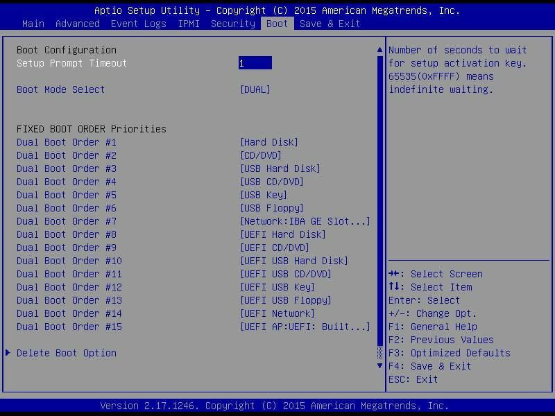
Safety information
Electrical safety
To prevent electrical shock hazard, disconnect the power cable from the electrical outlet
before relocating the system.
When adding or removing devices to or from the system, ensure that the power cables for
the devices are unplugged before the signal cables are connected. If possible, disconnect all
power cables from the existing system before you add a device.
Before connecting or removing signal cables from the motherboard, ensure that all power
cables are unplugged.
Seek professional assistance before using an adapter or extension cord. These devices could
interrupt the grounding circuit.
Make sure that your power supply is set to the correct voltage in your area.
If you are not sure about the voltage of the electrical outlet you are using, contact your local
power company.
If the power supply is broken, do not try to fix it by yourself. Contact a qualified service
technician or your local distributor.
Operation safety
Before installing the motherboard and adding devices on it, carefully read all the manuals
that came with the package.
Before using the product, make sure all cables are correctly connected and the power cables
are not damaged. If you detect any damage, contact your dealer immediately.
To avoid short circuits, keep paper clips, screws, and staples away from connectors, slots,
sockets and circuitry.
Avoid dust, humidity, and temperature extremes. Do not place the product in any area
where it may become wet.
Place the product on a stable surface.
If you encounter any technical problems with the product, contact your local distributor
Statement
All rights reserved. No part of this publication may be reproduced in any form or by any
means, without prior written permission from the publisher.
All trademarks are the properties of the respective owners.
All product specifications are subject to change without prior notice
2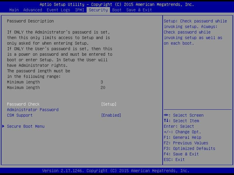
Revision History
Revision             Date (yyyy/mm/dd)          Changes
Version 1.0          2018/08/30                 Initial release
Version 1.1          2018/09/30                 Revision
Version 1.2          2019/06/27                 Change Product photo & Status LED specification

Packing list
□ HORUS200 Fanless Rugged System
□ CD (Driver + Quick Installation Guide)

Ordering information
Model Number         Description
HORUS200             1U Rackmount Fanless military computer with Intel Xeon D‐1587
                     processor, 24V DC‐IN, Operating Temperature 0 to 50°C

          If any of the above items is damaged or missing, please contact your local distributor.

                                                 3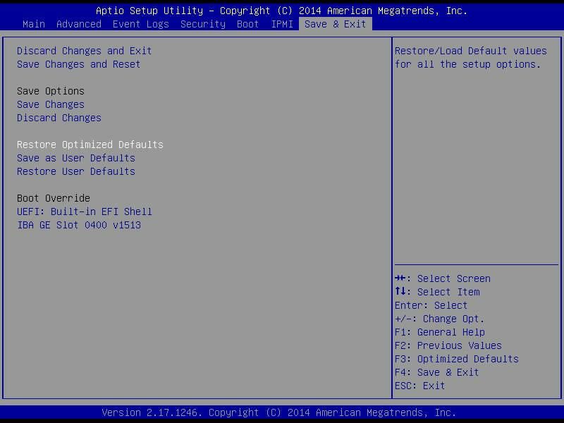
Table Contents

SAFETY INFORMATION .............................................................................................................................................. 2
    ELECTRICAL SAFETY ................................................................................................................................................................2
    OPERATION SAFETY ............................................................................................................................................................... 2
STATEMENT .............................................................................................................................................................. 2
REVISION HISTORY ................................................................................................................................................... 3
PACKING LIST ..............................................................................................................................................................3
ORDERING INFORMATION ........................................................................................................................................ 3
TABLE CONTENTS ........................................................................................................................................................4
CHAPTER 1: PRODUCT INTRODUCTION ......................................................................................................................5
    1.1 KEY FEATURES ................................................................................................................................................................5
    1.2 DIMENSIONS ................................................................................................................................................................. 6
    1.3 PANEL COMPONENT ........................................................................................................................................................7
CHAPTER 2: JUMPERS AND CONNECTORS LOCATIONS ................................................................................................7
    2.1 REAR PANEL CONNECTOR PIN DEFINITIONS ..........................................................................................................................7
       LED: .............................................................................................................................................................................7
       DC‐IN: 24V DC‐in ......................................................................................................................................................... 7
CHAPTER 3: BIOS SETUP ..........................................................................................................................................8-44

                                                                                           4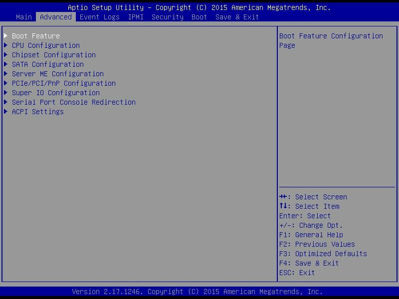
Chapter 1: Product Introduction

1.1 Key Features
System
                      Intel® Xeon® Processor D‐1587 Processor (24M SmartCache, 16 Cores/
CPU
                      32 Threads, Base Frequency 1.7GHz; Max Turbo Frequency 2.30 GHz)
Memory Type           Supports up to 128GB DDR4 ECC RDIMM
BIOS                  AMI® BIOS
Storage Device        SATA1: 2.5” SATAIII SSD 64GB
                      SATA2: 2.5” SATAIII SSD 2TB
Front I/O
VGA                     1 x DB15, resolution up to 1920x1200
10Gb Ethernet           2 x RJ45 (Via Intel® X557‐AT2)
1Gb Ethernet            2 x RJ45 (via Intel® i350‐AM2)
IPMI                    1 x RJ45
USB                     2 x USB 3.0
CMOS Battery            1 x Replacement CMOS Battery Tray
SSD Tray                1 x Dual Removable 2.5in SATA Enclosure
Power Button            1 x Power Button with LED backlight
HDD LED                 2 x Green LED
Status LED              4 x Dual color LED (reserved)
Secure Erase Button 1 (reserved)
Rear I/O
1Gb Ethernet            2 x RJ45 (via Intel® i350‐AM2)
COM                     1 x RS232
USB                     2 x USB 2.0
DC‐IN                   1 x Souriau 8ST7C08G98PN connector, 24V DC input
Ground Screw            1
Mechanical & Environment
Construction            Aluminum chassis with fanless design
Power                   24V DC‐in
Requirements            #Power consumption under 120 Watt.
Dimension               483 x 44.6 x 385mm
(W x H x D)             (19.02" x 1.76" x 15.16")
Weight                  10.6Kg
Operating Temp.         0 to 50°C (ambient with air flow)
Storage Temp.           ‐33 to 71°C
Relative Humidity       5% to 95%, non‐condensing
* Specifications are subject to change without notice*

                                               5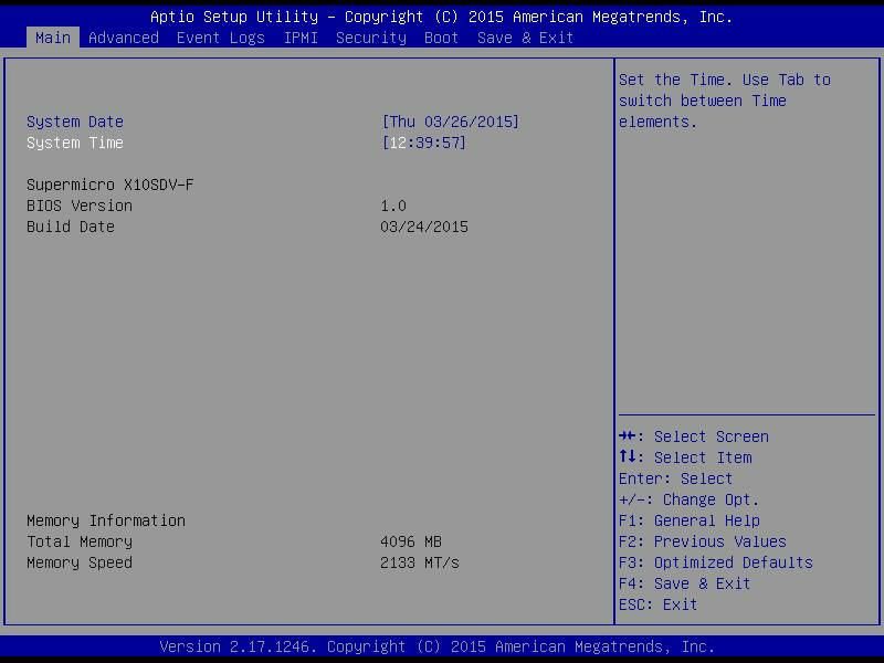
1.2 Dimensions

1.3 Panel Component

                      6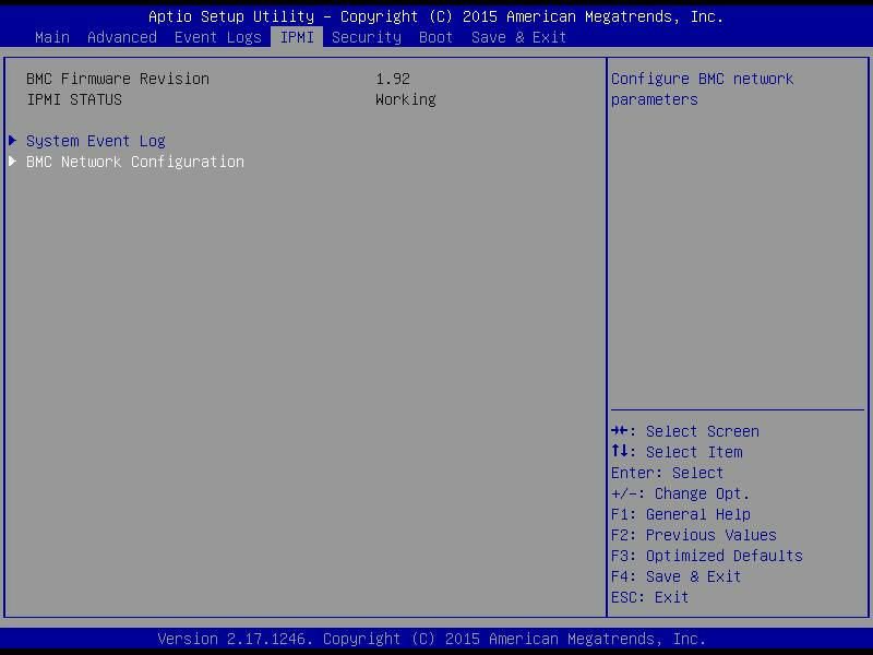
1      Secure Erase
   2      Dual Removable 2.5in SATA Enclosure
   3      IPMI
   4      LEDs
   5      2 x Gb Ethernet
   6      2 x 10Gb Ethernet
   7      VGA
   8      Replacement CMOS Battery Tray
   9      Power Button with LED backlight
   10     2 x USB3.0
   11     2 x Gb Ethernet
   12     2 x USB2.0
   13     COM Port (RS232)
   14     DC‐IN
   15     Ground Screw
Chapter 2: Jumpers and Connectors Locations

2.1 Rear Panel Connector Pin Definitions
  LED:
   LED  Function
   PWR Vehicle Power Ready
   LAN1 LAN1 Active LED
   LAN2 LAN2 Active LED
   OVHT Overheat LED*
   RDY   UID LED
   SSD   SSD2 Access LED
   Note: LED overheat alarm if an overheat condition is detected
         (CPU Temperature over 105℃)

  DC‐IN: 24V DC‐in
   Pin    Definition

   A       VIN 0V

   B       VIN 24V

                                                7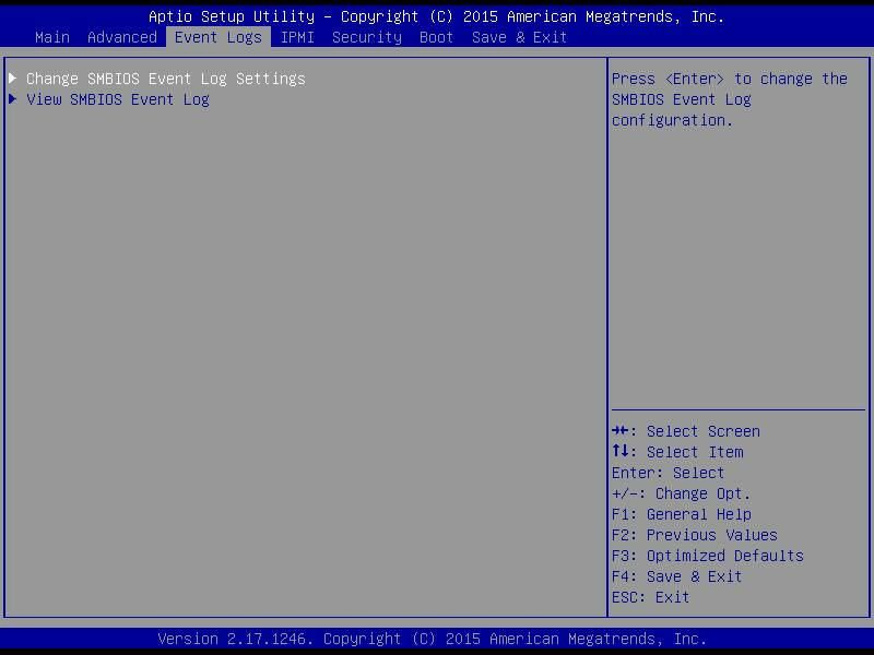
Chapter 3

                                     BIOS

3-1   Introduction
  This chapter describes the AMI BIOS setup utility for the System motherboard.
  The ROM BIOS is stored in a Flash EEPROM and can be easily updated.
  This chapter describes the basic navigation of the AMI BIOS setup utility setup
  screens. Note: For AMI BIOS Recovery, please refer to the UEFI BIOS Recovery
           Instructions in Appendix C.

      Starting BIOS Setup Utility
  To enter the AMI BIOS setup utility screens, press the  key while the
  system is booting up.
           Note: In most cases, the  key is used to invoke the AMI BIOS
           setup screen. There are a few cases when other keys are used, such as
           , , etc.

  Each main BIOS menu option is described in this manual. The Main BIOS setup
  menu screen has two main frames. The left frame displays all the options that can
  be configured. Grayed-out options cannot be configured. Options in blue can be
  configured by the user. The right frame displays the key legend. Above the key
  legend is an area reserved for a text message. When an option is selected in the
  left frame, it is highlighted in white. Often a text message will accompany it.
  (Note: the AMI BIOS has default text messages built in. It retains the option to
  include, omit, or change any of these text messages.)
  The AMI BIOS setup utility uses a key-based navigation system called "hot keys".
  Most of the AMI BIOS setup utility "hot keys" can be used at any time during the
  setup navigation process. These keys include , , , , arrow
  keys, etc.
           Note: Options printed in Bold are default settings.

      How To Change the Configuration Data
  The configuration data that determines the system parameters may be changed by
  entering the AMI BIOS setup utility. This setup utility can be accessed by pressing
   at the appropriate time during system boot.

                                         8
How to Start the Setup Utility
Normally, the only visible Power-On Self-Test (POST) routine is the memory test.
As the memory is being tested, press the key to enter the main menu of
the AMI BIOS setup utility. From the main menu, you can access the other setup
screens. An AMI BIOS identification string is displayed at the left bottom corner of
the screen, below the copyright message.
Warning: Do not update the BIOS unless your system has a BIOS-related issue.
Flashing the wrong BIOS can cause irreparable damage to the system. In no
event shall Perfectron be liable for direct, indirect, special, incidental, or consequential
dam-ages arising from a BIOS update. If you have to update the BIOS, do not shut
down or reset the system while the BIOS is updating. This is to avoid possible boot
failure.
3-2 Main Setup
When you first enter the AMI BIOS setup utility, you will enter the Main setup screen.
You can always return to the Main setup screen by selecting the Main tab on the
top of the screen. The Main BIOS Setup screen is shown below.
9The following Main menu items will display:
System Date/System Time
Use this feature to change the system date and time. Highlight System Date or
System Time using the arrow keys. Enter new values using the keyboard. Press
the key or the arrow keys to move between fields. The date must be entered
in Day MM/DD/YY format. The time is entered in HH:MM:SS format.
Note: The time is in the 24-hour format. For example, 5:30 P.M. appears
as 17:30:00.
The following BIOS items will also be displayed:
Model Name
Version
Build Date
Memory Information
Total Memory
This displays the total size of memory available in the system.
103-3 Advanced Setup Con igurations
Use the arrow keys to select Boot Setup and press to access the submenu
items.
Warning: Take caution when changing the Advanced settings. An incorrect value, a
very high DRAM frequency, or an incorrect DRAM timing setting may make the system
unstable. When this occurs, revert to the default to the manufacture default settings.
Boot Feature
Quiet Boot
Use this feature to select the screen display between the POST messages and the
OEM logo upon bootup. Select Disabled to display the POST messages. Select
Enabled to display the OEM logo instead of the normal POST messages. The op-
tions are Enabled and Disabled.
AddOn ROM Display Mode
Use this feature to set the display mode for the Option ROM. Select Keep Current to
display the current AddOn ROM setting. Select Force BIOS to use the Option ROM
display set by the system BIOS. The options are Force BIOS and Keep Current.
Bootup NumLock State
Use this feature to set the Power-on state for the key. The options
are Off and On.
11Wait For 'F1' If Error
Use this feature to force the system to wait until the 'F1' key is pressed if an error
occurs. The options are Disabled and Enabled.
INT19 (Interrupt 19) Trap Response
Interrupt 19 is the software interrupt that handles the boot disk function. When this
item is set to Immediate, the ROM BIOS of the host adaptors will "capture" Inter-
rupt 19 at bootup immediately and allow the drives that are attached to these host
adaptors to function as bootable disks. If this item is set to Postponed, the ROM
BIOS of the host adaptors will not capture Interrupt 19 immediately and allow the
drives attached to these adaptors to function as bootable devices at bootup. The
options are Immediate and Postponed.
Re-try Boot
If this item is enabled, the BIOS will automatically reboot the system from a speci-
fied boot device after its initial boot failure. The options are Disabled, Legacy
Boot, and EFI Boot.
Power Configuration
Watch Dog Function
If enabled, the Watch Dog Timer will allow the system to reset or generate NMI
based on jumper settings when it is expired for more than 5 minutes. The options
are Enabled and Disabled.
Power Button Function
This feature controls how the system shuts down when the power button is pressed.
Select 4_Seconds_Override for the user to power off the system after pressing and
holding the power button for 4 seconds or longer. Select Instant Off to instantly
power off the system as soon as the user presses the power button. The options
are 4 Seconds Override and Instant Off.
Restore on AC Power Loss
Use this feature to set the power state after a power outage. Select Stay-Off for the
system power to remain off after a power loss. Select Power-On for the system
power to be turned on after a power loss. Select Last State to allow the system
to resume its last power state before a power loss. The options are Power-On,
Stay-Off and Last State.
12CPU Configuration
The following CPU information will be displayed:
• Processor ID
• Processor Frequency
• Processor Max Ratio
• Processor Min Ratio
• Microcode Revision
• L1 Cache RAM
• L2 Cache RAM
• L3 Cache Ram
• CPU Version
Clock Spread Spectrum
If this feature is set to Enabled, the BIOS utility will monitor the level of Electro-
magnetic Interference caused by the components and will attempt to reduce the
interference whenever needed. The options are Enabled and Disabled.
Hyper-Threading (ALL)
Select Enable to use Intel Hyper-Threading Technology to enhance CPU perfor-
mance. The options are Enable and Disable.
Cores Enabled
Set a numeric value to enable the number of cores. (Please refer to Intel's website
for more information.) Enter 0 to enable all cores.
Monitor/Mwait
Select Enabled to enable the Monitor/MWait instructions. The Monitor instruction
monitors a region of memory for writes, and MWait instructions instruct the CPU to
stop until the monitored region begins to write. The options are Enable and Disable.
13Execute Disable Bit (Available if supported by the OS & the CPU)
Select Enabled to enable the Execute-Disable Bit which will allow the processor
to designate areas in the system memory where an application code can execute
and where it cannot, thus preventing a worm or a virus from flooding illegal codes
to overwhelm the processor or damage the system during an attack. The default is
Enable. (Refer to the Intel® and Microsoft® websites for more information.)
PPIN Control
Select Unlock/Enable to use the Protected-Processor Inventory Number (PPIN) in
the system. The options are Unlock/Enable and Unlock/Disable.
Hardware Prefetcher (Available when supported by the CPU)
If set to Enabled, the hardware prefetcher will prefetch streams of data and instruc-
tions from the main memory to the L2 cache to improve CPU performance. The
options are Disable and Enable.
Adjacent Cache Prefetch (Available when supported by the CPU)
The CPU prefetches the cache line for 64 bytes if this feature is set to Disabled.
The CPU prefetches both cache lines for 128 bytes as comprised if this feature is
set to Enable.
DCU Streamer Prefetcher (Available when supported by the CPU)
Select Enabled to enable the DCU (Data Cache Unit) Streamer Prefetcher which
will stream and prefetch data and send it to the Level 1 data cache to improve data
processing and system performance. The options are Disable and Enable.
DCU IP Prefetcher (Available when supported by the CPU)
Select Enabled for DCU (Data Cache Unit) IP Prefetcher support, which will prefetch
IP addresses to improve network connectivity and system performance. The options
are Disable and Enable.
Direct Cache Access (DCA Support)
Select Enabled to use Intel's DCA (Direct Cache Access) Technology to improve
data transfer efficienc . The options are Enable and Disable.
X2APIC
Select Enable to activate APIC (Advanced Programmable Interrupt Controller) sup-
port. The options are Enable and Disable.
AES-NI
Select Enable to use the Intel Advanced Encryption Standard (AES) New Instruc-
tions (NI) to ensure data security. The options are Enable and Disable.
14Intel® Virtualization Technology (Available when supported by the CPU)
Select Enabled to support Intel ® Virtualization Technology, which will allow one
platform to run multiple operating systems and applications in independent parti-
tions, creating multiple "virtual" systems in one physical computer. The options
are Enable and Disable.
Note: If a change is made to this setting, you will need to reboot the
system for the change to take effect. Refer to Intel’s website for detailed
information.
Advanced Power Management Configuration
This section is used to configure the following CPU Power Management settings.
EIST (P-States)
EIST (Enhanced Intel SpeedStep Technology) allows the system to automatically
adjust processor voltage and core frequency to reduce power consumption and
heat dissipation. The options are Disable and Enable.
If the above is set to Enable, CPU P State will display:
CPU P State Control
P State Domain
This feature allows the user to indicate the P-State domain for each logical
process in the system. All processes indicate the same domain in the same
package. The options are ALL and ONE.
P-State Coordination
This feature allows the user to change the P-State (Power-Performance State)
coordination type. P-State is also known as "SpeedStep" for Intel processors. Se-
lect HW_ALL to change the P-State coordination type for hardware components
only. Select SW_ALL to change the P-State coordination type for all software
installed in the system. Select SW_ANY to change the P-State coordination
type for a software program in the system. The options are HW_All, SW_ALL,
and SW_ANY.
Energy Efficient P-State
Select Enable to support power-saving mode for P-State. The options are Dis-
able and Enable.
15Boot Performance Mode
This feature allows the user to select the performance state that the BIOS will
set before the operating system handoff. The options are Max Performance
and Max Efficient
Turbo Mode
Select Enable for processor cores to run faster than the frequency specified by
the manufacturer. The options are Disable and Enable.
CPU HWPM State Control
Enable CPU HWPM
Select Enable for better CPU energy performance. The options are Disable,
HWPM NATIVE MODE, and HWPM OOB MODE.
Enable CPU Autonomous Cstate
Use this feature to enable CPU Autonomous C State, which converts HALT
instructions to Mwait.. The options are Disable and Enable.
CPU C State Control
CPU C State
Use this feature to enable the enahnced C State of the CPU. The options are
Disable and Enable.
Package C State Limit
This feature allows the user to set the limit on the C State package register.
The options are C0/C1 State, C2 State, C6 (Non Retention) State, and C6
(Rentention) state.
CPU C3 Report
Select Enabled to allow the BIOS to report the CPU C3 State (ACPI C2) to the
operating system. During the CPU C3 State, the CPU clock generator is turned
off. The options are Enable and Disable.
CPU C6 Report
Select Enabled to allow the BIOS to report the CPU C6 State (ACPI C3) to the
operating system. During the CPU C6 State, the power to all cache is turned
off. The options are Enable and Disable.
16Enhanced Halt State (C1E)
Select Enabled to use Enhanced Halt-State technology, which will significantl
reduce the CPU's power consumption by reducing the CPU's clock cycle and
voltage during a Halt-state. The options are Disable and Enable.
CPU T State Control
ACPI (Advanced Configuration Power Interface) T-States
Select Enable to support CPU throttling by the operating system to reduce power
consumption. The options are Enable and Disable.
CPU Advanced PM Tuning
Energy Perf BIAS
Energy Performance Tuning
When enabled, this item selects whether the BIOS or Operating System can
turn on the energy performance bias tuning. The options are Enable and
Disable.
If the above is set to Disable, Energy Performance BIAS Setting will display:
Energy Performance BIAS Setting
This feature allows balancing Power Efficiency vs Performance. This will
override whatever setting is in the Operating System. The options are Per-
formance, Balanced Performance, Balanced Power, and Power.
Power/Performance Switch
This feature allows dynamic switching between Power and Performance
power efficienc . The options are Enable and Disable.
Workload Configuration
This feature allows for optimization of workload. Balanced is recommended.
The options are Balanced and I/O Sensitive.
Program PowerCTL_MSR
PKG C-state Lat. Neg.
Use this feature to indicate whether latency should be negotiated with PCH
for packaging C-States. The options are Enable and Disable.
17SAPM Control
This feature indicates whether the PCU should control the System Agent
PM using its power-performance tuning algorithm. The options are Enable
and Disable.
Energy Efficient Turbo
Use this feature to enable energy efficient turbo mode. The options are En-
able and Disable.
DRAM RAPL Configuration
DRAM RAPL Extended Range
Use this feature to set the DRAM Running Average Power Limit (RAPL)
Extended Range. The options are Disable and Enable.
Chipset Configuration
Warning: Setting the wrong values in the following features may cause the system
to malfunction.
North Bridge
This feature allows the user to configure the following North Bridge settings.
IIO Configuration
EV DFX (Device Function On-Hide) Features
When this feature is set to Enable, the EV_DFX Lock Bits that are located on a
processor will always remain clear during electric tuning. The options are Dis-
able and Enable.
IIO1 Configuration
M.2 PCI-E 3.0 X4
This item configures the link speed of the PCI-E port specified by the user. The
options are Gen 1 (Generation 1) (2.5 GT/s), Gen 2 (Generation 2) (5 GT/s) and
Gen 3 (Generation 3) (8 GT/s).
SLOT 7 PCI-E 3.0 X16)
This item configures the link speed of the PCI-E port specified by the user. The
options are Gen 1 (Generation 1) (2.5 GT/s), Gen 2 (Generation 2) (5 GT/s) and
Gen 3 (Generation 3) (8 GT/s).
18IOAT (Intel® IO Acceleration) Configuration
Enable IOAT
Select Enable to enable Intel I/OAT (I/O Acceleration Technology) support, which
significantly reduces CPU overhead by leveraging CPU architectural improve-
ments and freeing the system resource for other tasks. The options are Enable
and Disable.
No Snoop
Select Enable to support no-snoop mode for each CB device. The options are
Disable and Enable.
Intel® VT for Directed I/O (VT-d)
Intel® VT for Directed I/O (VT-d)
Select Enable to use Intel® Virtualization Technology support for Direct I/O VT-d
support by reporting the I/O device assignments to the VMM (Virtual Machine
Monitor) through the DMAR ACPI Tables. This feature offers fully-protected I/O
resource sharing across Intel platforms, providing greater reliability, security and
availability in networking and data-sharing. The options are Enable and Disable.
ACS Control
Use this feature to program Access Control Services (ACS) to the PCI-E Root
Port Bridges. The options are Enable and Disable.
Interrupt Remapping
Select Enable for Interrupt Remapping support to enhance system performance.
The options are Enable and Disable.
Memory Configuration
Enforce POR
Select Enable to enforce POR restrictions on DDR4 frequency and voltage
programming. The options are Enabled and Disabled.
Memory Frequency
Use this feature to set the maximum memory frequency for onboard memory
modules. The options are Auto, 1333, 1400, 1600, 1800, 1867, 2000, 2133,
2200, 2400, 2600, 2667, and Reserved (Do not select Reserved).
19Data Scrambling
Select Enabled to enable data scrambling to enhance system performance and
data integrity. The options are Auto, Disabled and Enabled.
DRAM RAPL Baseline
Use this feature to set the run-time power-limit baseline for DRAM modules. The
options are Disable, DRAM RAPL Mode 0, and DRAM RAPL Mode 1.
Set Throttling Mode
Throttling improves reliability and reduces power consumption in the processor
via automatic voltage control during processor idle states. The options are Dis-
abled and CLTT (Closed Loop Thermal Throttling).
A7 Mode
Select Enabled to support the A7 (Addressing) mode to improve memory perfor-
mance. The options are Enable and Disable.
DIMM Information
This item displays the status of a DIMM module specified by the user.
• DIMMA1
• DIMMB1
• DIMMA2
• DIMMB2
Memory RAS (Reliability_Availability_Serviceability)
Configuration
Use this submenu to configure the following Memory RAS settings.
Patrol Scrub
Patrol Scrubbing is a process that allows the CPU to correct correctable memory
errors detected on a memory module and send the correction to the requestor
(the original source). When this item is set to Enabled, the IO hub will read and
write back one cache line every 16K cycles, if there is no delay caused by internal
processing. By using this method, roughly 64 GB of memory behind the IO hub
will be scrubbed every day. The options are Enable and Disable.
20Patrol Scrub Interval
This feature allows you to decide how many hours the system should wait before
the next complete patrol scrub is performed. Use the keyboard to enter a value
from 0-24. The Default setting is 24.
Demand Scrub
Demand Scrubbing is a process that allows the CPU to correct correctable
memory errors found on a memory module. When the CPU or I/O issues a
demand-read command, and the read data from memory turns out to be a
correctable error, the error is corrected and sent to the requestor (the original
source). Memory is updated as well. Select Enable to use Demand Scrubbing
for ECC memory correction. The options are Enable and Disable.
Device Tagging
Select Enable to support device tagging. The options are Disable and Enable.
South Bridge
The following South Bridge information will display:
• USB Configuratio
• USB Module Version
• USB Devices
Legacy USB Support
This feature enables support for legacy USB devices. Select Auto to disable legacy
support if USB devices are not present. Select Disable to have USB devices avail-
able only for EFI applications. The options are Enabled, Disabled and Auto.
XHCI Hand-Off
This is a work-around solution for operating systems that do not support XHCI (Ex-
tensible Host Controller Interface) hand-off. The XHCI ownership change should be
claimed by the XHCI driver. The settings are Enabled and Disabled.
EHCI Hand-Off
This item is for the Operating Systems that do not support Enhanced Host Controller
Interface (EHCI) hand-off. When this item is enabled, EHCI ownership change will
be claimed by the EHCI driver. The settings are Enabled and Disabled.
USB 3.0 Support
Select Enabled for USB 3.0 support. The options are Disabled, Enabled and Auto.
21EHCI1
Select Enabled to enable EHCI (Enhanced Host Controller Interface) support on
USB 2.0 connector #1 (at least one USB 2.0 connector should be enabled for EHCI
support). The options are Disabled and Enabled.
EHCI2
Select Enabled to enable EHCI (Enhanced Host Controller Interface) support on
USB 2.0 connector #2 (at least one USB 2.0 connector should be enabled for EHCI
support). The options are Disabled and Enabled.
XHCI Pre-Boot Driver
Select Enabled to enable XHCI (Extensible Host Controller Interface) support on a
pre-boot drive specified by the user. The options are Enabled and Disabled.
SATA Configuration
When this submenu is selected, the AMI BIOS automatically detects the presence
of the SATA devices that are supported by the Intel PCH chip and displays the
following items:
SATA Controller
This item enables or disables the onboard SATA controller supported by the Intel
PCH chip. The options are Enabled and Disabled.
Configure SATA as
Select IDE to configure a SATA drive specified by the user as an IDE drive. Select
AHCI to configure a SATA drive specified by the user as an AHCI drive. Select
RAID to configure a SATA drive specified by the user as a RAID drive. The options
are IDE, AHCI, and RAID.
*If the item above "Configure SATA as" is set to AHCI, the following items
will display:
SATA AHCI LPM
Use this feature to enable the Link Power Management for SATA AHCI. The options
are Disabled and Enabled.
Support Aggressive Link Power Management
When this item is set to Enabled, the SATA AHCI controller manages the power
usage of the SATA link. The controller will put the link in a low power mode during
extended periods of I/O inactivity, and will return the link to an active state when
I/O activity resumes. The options are Enabled and Disabled.
22SATA Port 0~ Port 5
This item displays the information detected on the installed SATA drive on the
particular SATA port.
• Model number of drive and capacity
• Software Preserve Support
Port 0 ~ Port 5 Hot Plug
This feature designates this port for hot plugging. Set this item to Enabled for
hot-plugging support, which will allow the user to replace a SATA drive without
shutting down the system. The options are Enabled and Disabled.
Port 0 ~ Port 5 Spin Up Device
On an edge detect from 0 to 1, set this item to allow the PCH to initialize the
device. The options are Enabled and Disabled.
Port 0 ~ Port 5 SATA Device Type
Use this item to specify if the SATA port specified by the user should be con-
nected to a Solid State drive or a Hard Disk Drive. The options are Hard Disk
Drive and Solid State Drive.
*If the item above "Configure SATA as" is set to IDE, the following items
will display:
Port 0 ~ Port 5 SATA Device Type (Available when a SATA port is
detected)
Use this item to specify if the SATA port specified by the user should be con-
nected to a Solid State drive or a Hard Disk Drive. The options are Hard Disk
Drive and Solid State Drive.
Server ME (Management Engine) Configuration
This feature displays the following system ME configuration settings.
• General ME Configuratio
• Operational Firmware Version
• ME Firmware Type
• Recovery Firmware Version
• ME Firmware Features
23• ME Firmware Status #1
• ME Firmware Status #2
• Current State
• Error Code
PCIe/PCI/PnP Configuration
The following information will display:
• PCI Bus Driver Version
• PCI Devices Common Settings:
PCI PERR/SERR Support
Select Enabled to allow a PCI device to generate a PERR/SERR number for a PCI
Bus Signal Error Event. The options are Enabled and Disabled.
SR-IOV (Available if the system supports Single-Root Virtualization)
Select Enabled for Single-Root IO Virtualization support. The options are Enabled
and Disabled.
Maximum Payload
Use this feature to select the setting for the PCI Express maximum payload size.
The options are Auto, 128 Bytes, 256 Bytes, 512 Bytes, 1024 Bytes, 2048 Bytes,
and 4096 Bytes.
Relaxed Ordering
Select Enable to enable Relaxed Ordering support which will allow certain transac-
tions to violate the strict-ordering rules of PCI bus for a transaction to be completed
prior to other transactions that have already been enqueued. The options are Dis-
able and Enable.
Extended Tag
Use this item to allow a device to use the 8-bit tag field as a requester. The options
are Disabled and Enabled.
ARI Forwarding
When this feature is enabled, the Downstream Port disables its traditional device
number to 0 when turning Type1 Configuration Request into a Type0 Configuratio
Request. The default value is Disabled.
24M.2 PCI-E 3.0 X4
Use this feature to select which firmware type to be loaded for the add-on card in
this slot. The options are Disabled, Legacy, and EFI.
SLOT 7 PCI-E 3.0 X16
Use this feature to select which firmware type to be loaded for the add-on card in
this slot. The options are Disabled, Legacy, and EFI.
Onboard LAN Option ROM Type
Select Enabled to enable Option ROM support to boot the computer using a
network device specified by the user. The options are Disabled, Legacy and EFI.
Onboard LAN1 Option ROM
Use this option to select the type of device installed in LAN Port1 used for system
boot. The default setting for LAN1 Option ROM is PXE.
Onboard LAN2 Option ROM
Use this option to select the type of device installed in LAN Port2 used for system
boot. The default setting for LAN2 Option ROM is Disabled.
Onboard Video Option ROM
Use this item to select the Onboard Video Option ROM type. The options are
Disabled, Legacy, and EFI.
VGA Priority
This feature allows the user to select the graphics adapter to be used as the primary
boot device. The options are Onboard, and Offboard.
Network Stack
Select Enabled enable PXE (Preboot Execution Environment) or UEFI (Unifie
Extensible Firmware Interface) for network stack support. The options are Enabled
and Disabled.
Super IO Configuration
Super IO Chip AST2400
Serial Port 1 Configuration
This submenu allows the user the configure settings of Serial Port 1 or Serial Port 2.
25Serial Port
Select Enabled to enable the selected onboard serial port. The options are Enabled
and Disabled.
Device Settings
This item displays the status of a serial part specified by the user.
Change Port 1 Settings
This feature specifies the base I/O port address and the Interrupt Request address
of a serial port specified by the user. Select Auto to allow the BIOS to automatically
assign the base I/O and IRQ address.
The options for Serial Port 1 are Auto, (IO=3F8h; IRQ=4), (IO=3F8h; IRQ=3, 4, 5,
6, 7, 9, 10, 11, 12), (IO=2F8h; IRQ=3, 4, 5, 6, 7, 9, 10, 11, 12), (IO=3E8h; IRQ=3,
4, 5, 6, 7, 9, 10, 11, 12) and (IO=2E8h; IRQ=3, 4, 5, 6, 7, 9, 10, 11, 12).
Serial Port Console Redirection
COM1 Console Redirection
Console Redirection
Select Enabled to enable console redirection support for a serial port specified by
the user. The options are Enabled and Disabled.
COM1 Console Redirection Settings
This feature allows the user to specify how the host computer will exchange data
with the client computer, which is the remote computer used by the user.
Terminal Type
This feature allows the user to select the target terminal emulation type for Console
Redirection. Select VT100 to use the ASCII Character set. Select VT100+ to add
color and function key support. Select ANSI to use the Extended ASCII Character
Set. Select VT-UTF8 to use UTF8 encoding to map Unicode characters into one or
more bytes. The options are ANSI, VT100, VT100+, and VT-UTF8.
Bits Per second
Use this feature to set the transmission speed for a serial port used in Console
Redirection. Make sure that the same speed is used in the host computer and the
client computer. A lower transmission speed may be required for long and busy
lines. The options are 9600, 19200, 38400, 57600 and 115200 (bits per second).
26Data Bits
Use this feature to set the data transmission size for Console Redirection. The
options are 7 Bits and 8 Bits.
Parity
A parity bit can be sent along with regular data bits to detect data transmission
errors. Select Even if the parity bit is set to 0, and the number of 1's in data bits
is even. Select Odd if the parity bit is set to 0, and the number of 1's in data bits
is odd. Select None if you do not want to send a parity bit with your data bits in
transmission. Select Mark to add a mark as a parity bit to be sent along with the
data bits. Select Space to add a Space as a parity bit to be sent with your data
bits. The options are None, Even, Odd, Mark and Space.
Stop Bits
A stop bit indicates the end of a serial data packet. Select 1 Stop Bit for standard
serial data communication. Select 2 Stop Bits if slower devices are used. The op-
tions are 1 and 2.
Flow Control
Use this feature to set the flow control for Console Redirection to prevent data loss
caused by buffer overflo . Send a "Stop" signal to stop sending data when the re-
ceiving buffer is full. Send a "Start" signal to start sending data when the receiving
buffer is empty. The options are None and Hardware RTS/CTS.
VT-UTF8 Combo Key Support
Select Enabled to enable VT-UTF8 Combination Key support for ANSI/VT100 ter-
minals. The options are Enabled and Disabled.
Recorder Mode
Select Enabled to capture the data displayed on a terminal and send it as text mes-
sages to a remote server. The options are Disabled and Enabled.
Resolution 100x31
Select Enabled for extended-terminal resolution support. The options are Disabled
and Enabled.
Legacy OS Redirection Resolution
Use this feature to select the number of rows and columns used in Console Redi-
rection for legacy OS support. The options are 80x24 and 80x25.
27Putty KeyPad
This feature selects the settings for Function Keys and KeyPad used for Putty,
which is a terminal emulator designed for the Windows OS. The options are VT100,
LINUX, XTERMR6, SC0, ESCN, and VT400.
Redirection After BIOS Post
Use this feature to enable or disable legacy console redirection after BIOS POST.
When set to Bootloader, legacy console redirection is disabled before booting the
OS. When set to Always Enable, legacy console redirection remains enabled when
booting the OS. The options are Always Enable and Bootloader.
SOL Console Redirection
Select Enabled to use the SOL port for Console Redirection. The options are En-
abled and Disabled.
*If the item above set to Enabled, the following items will become available
for user's configuration:
SOL Console Redirection Settings
Use this feature to specify how the host computer will exchange data with the client
computer, which is the remote computer used by the user.
Terminal Type
Use this feature to select the target terminal emulation type for Console Redirec-
tion. Select VT100 to use the ASCII Character set. Select VT100+ to add color and
function key support. Select ANSI to use the Extended ASCII Character Set. Select
VT-UTF8 to use UTF8 encoding to map Unicode characters into one or more bytes.
The options are ANSI, VT100, VT100+, and VT-UTF8.
Bits Per second
Use this feature to set the transmission speed for a serial port used in Console
Redirection. Make sure that the same speed is used in the host computer and the
client computer. A lower transmission speed may be required for long and busy
lines. The options are 9600, 19200, 38400, 57600 and 115200 (bits per second).
Data Bits
Use this feature to set the data transmission size for Console Redirection. The
options are 7 (Bits) and 8 (Bits).
28Parity
A parity bit can be sent along with regular data bits to detect data transmission
errors. Select Even if the parity bit is set to 0, and the number of 1's in data bits
is even. Select Odd if the parity bit is set to 0, and the number of 1's in data bits
is odd. Select None if you do not want to send a parity bit with your data bits in
transmission. Select Mark to add a mark as a parity bit to be sent along with the
data bits. Select Space to add a Space as a parity bit to be sent with your data
bits. The options are None, Even, Odd, Mark and Space.
Stop Bits
A stop bit indicates the end of a serial data packet. Select 1 Stop Bit for standard
serial data communication. Select 2 Stop Bits if slower devices are used. The op-
tions are 1 and 2.
Flow Control
Use this feature to set the flow control for Console Redirection to prevent data loss
caused by buffer overflo . Send a "Stop" signal to stop sending data when the re-
ceiving buffer is full. Send a "Start" signal to start sending data when the receiving
buffer is empty. The options are None and Hardware RTS/CTS.
VT-UTF8 Combo Key Support
Select Enabled to enable VT-UTF8 Combination Key support for ANSI/VT100 ter-
minals. The options are Enabled and Disabled.
Recorder Mode
Select Enabled to capture the data displayed on a terminal and send it as text mes-
sages to a remote server. The options are Disabled and Enabled.
Resolution 100x31
Select Enabled for extended-terminal resolution support. The options are Disabled
and Enabled.
Legacy OS Redirection Resolution
Use this feature to select the number of rows and columns used in Console Redi-
rection for legacy OS support. The options are 80x24 and 80x25.
Putty KeyPad
This feature selects Function Keys and KeyPad settings for Putty, which is a terminal
emulator designed for the Windows OS. The options are VT100, LINUX, XTERMR6,
SCO, ESCN, and VT400.
29Redirection After BIOS Post
Use this feature to enable or disable legacy Console Redirection after BIOS POST.
When set to Bootloader, legacy Console Redirection is disabled before booting the
OS. When set to Always Enable, legacy Console Redirection remains enabled when
booting the OS. The options are Always Enable and Bootloader.
Serial Port for Out-of-Band Management/Windows Emergency Management
Services (EMS)
The submenu allows the user to configure Console Redirection settings to support
Out-of-Band Serial Port management.
EMS (Emergency Management Services) Console Redirection
Select Enabled to use a COM port selected by the user for EMS Console Redirec-
tion. The options are Enabled and Disabled.
*If the item above set to Enabled, the following items will become available
for user's configuration:
EMS Console Redirection Settings
This feature allows the user to specify how the host computer will exchange data
with the client computer, which is the remote computer used by the user.
Out-of-Band Management Port
The feature selects a serial port in a client server to be used by the Microsoft
Windows Emergency Management Services (EMS) to communicate with a remote
host server. The options are COM1 and COM2/SOL.
Terminal Type
Use this feature to select the target terminal emulation type for Console Redirec-
tion. Select VT100 to use the ASCII character set. Select VT100+ to add color and
function key support. Select ANSI to use the extended ASCII character set. Select
VT-UTF8 to use UTF8 encoding to map Unicode characters into one or more bytes.
The options are ANSI, VT100, VT100+, and VT-UTF8.
Bits Per Second
This item sets the transmission speed for a serial port used in Console Redirec-
tion. Make sure that the same speed is used in the host computer and the client
computer. A lower transmission speed may be required for long and busy lines. The
options are 9600, 19200, 57600, and 115200 (bits per second).
30Flow Control
Use this item to set the flow control for Console Redirection to prevent data loss
caused by buffer overflo . Send a "Stop" signal to stop sending data when the re-
ceiving buffer is full. Send a "Start" signal to start sending data when the receiving
buffer is empty. The options are None, Hardware RTS/CTS, and Software Xon/Xoff.
Data Bits
Use this feature to set the data transmission size for Console Redirection. The
options are 7 (Bits) and 8 (Bits).
Parity
A parity bit can be sent along with regular data bits to detect data transmission
errors. Select Even if the parity bit is set to 0, and the number of 1's in data bits
is even. Select Odd if the parity bit is set to 0, and the number of 1's in data bits
is odd. Select None if you do not want to send a parity bit with your data bits in
transmission. Select Mark to add a mark as a parity bit to be sent along with the
data bits. Select Space to add a Space as a parity bit to be sent with your data
bits. The options are None, Even, Odd, Mark and Space.
Stop Bits
A stop bit indicates the end of a serial data packet. Select 1 Stop Bit for standard
serial data communication. Select 2 Stop Bits if slower devices are used. The op-
tions are 1 and 2.
ACPI Settings
WHEA Support
This feature Enables the Windows Hardware Error Architecture (WHEA) support for
the Windows 2008 (or a later version) operating system. The options are Enabled
and Disabled.
High Precision Event Timer
Select Enabled to activate the High Performance Event Timer (HPET) that produces
periodic interrupts at a much higher frequency than a Real-time Clock (RTC) does in
synchronizing multimedia streams, providing smooth playback and reducing the de-
pendency on other timestamp calculation devices, such as an x86 RDTSC Instruc-
tion embedded in the CPU. The High Performance Event Timer is used to replace
the 8254 Programmable Interval Timer. The options are Enabled and Disabled.
PCI AER Support
Select Enabed to enable the ACPI OS to manage PCI Advanced Error Reporting.
The options are Enabled and Disabled.
313-4 Event Logs
Use this feature to configure Event Log settings.
Change SMBIOS Event Log Settings
Enabling/Disabling Options
SMBIOS Event Log
Change this item to enable or disable all features of the SMBIOS Event Logging
during system boot. The options are Enabled and Disabled.
Runtime Error Logging Support
Select Enabled to support Runtime Error Logging. The options are Enable and Dis-
able. If this item is set to Enable, the following item will be available for configur tion:
Memory Corrected Error Enabling (Available when the item above -
Runtime Error Logging Support is set to Enable)
Select Enable for the BIOS to correct a memory error if it is correctable. The options
are Disable and Enable.
Memory Correctable Error Threshold
Use this item to enter the threshold value for correctable memory errors. The default
setting is 10.
32PCI-Ex (PCI-Express) Error Enable
Select Yes for the BIOS to correct errors occurred in the PCI-E slots. The options
are Yes and No.
Erasing Settings
Erase Event Log
If No is selected, data stored in the event log will not be erased. Select Yes, Next
Reset, data in the event log will be erased upon next system reboot. Select Yes,
Every Reset, data in the event log will be erased upon every system reboot. The
options are No, Yes, Next reset, and Yes, Every reset.
When Log is Full
Select Erase Immediately for all messages to be automatically erased from the
event log when the event log memory is full. The options are Do Nothing and
Erase Immediately.
SMBIOS Event Long Standard Settings
Log System Boot Event
This option toggles the System Boot Event logging to enabled or disabled. The
options are Disabled and Enabled.
MECI
The Multiple Event Count Increment (MECI) counter counts the number of occurenc-
es that a duplicate event must happen before the MECI counter is incremented.
This is a numeric value. The default value is 1.
METW
The Multiple Event Time Window (METW) defines number of minutes must pass
between duplicate log events before MECI is incremented. This is in minutes, from
0 to 99. The default value is 60.
Note: After making changes on a setting, be sure to reboot the system for
the changes to take effect.
View SMBIOS Event Log
This section displays the contents of the SMBIOS Event Log.
333-5 IPMI
Use this feature to configure Intelligent Platform Management Interface (IPMI)
settings.
BMC Firmware Revision
This item indicates the IPMI firmware revision used in your system.
IPMI Status (Baseboard Management Controller)
This item indicates the status of the IPMI firmware installed in your system.
System Event Log
Enabling/Disabling Options
SEL Components
Select Enabled for all system event logging at bootup. The options are Enabled
and Disabled.
Erasing Settings
Erase SEL
Select Yes, On next reset to erase all system event logs upon next system reboot.
Select Yes, On every reset to erase all system event logs upon each system reboot.
Select No to keep all system event logs after each system reboot. The options are
No, Yes, On next reset, and Yes, On every reset.
34When SEL is Full
This feature allows the user to decide what the BIOS should do when the system
event log is full. Select Erase Immediately to erase all events in the log when the
system event log is full. The options are Do Nothing and Erase Immediately.
Note: After making changes on a setting, be sure to reboot the system for
the changes to take effect.
BMC Network Configuration
BMC Network Configuration
IPMI LAN Selection
This item displays the IPMI LAN setting. The default setting is Failover.
IPMI Network Link Status
This item displays the IPMI Network Link status. The default setting is Shared LAN.
Update IPMI LAN Configuration
Select Yes for the BIOS to implement all IP/MAC address changes at the next
system boot. The options are No and Yes
Configuration Address Source
This feature allows the user to select the source of the IP address for this com-
puter. If Static is selected, you will need to know the IP address of this computer
and enter it to the system manually in the field. If DHCP is selected, the BIOS will
search for a DHCP (Dynamic Host Configuration Protocol) server in the network
that is attached to and request the next available IP address for this computer.
The options are DHCP and Static. The following items are assigned IP addresses
automatically if DHCP is selected.
Current Configuration Address Source
This item displays the current configuration address for this computer.
Station IP Address
This item displays the Station IP address for this computer. This should be in decimal
and in dotted quad form (i.e., 192.168.10.253).
Subnet Mask
This item displays the sub-network that this computer belongs to. The value of each
three-digit number separated by dots should not exceed 255.
35Station MAC Address
This item displays the Station MAC address for this computer. Mac addresses are
6 two-digit hexadecimal numbers.
Gateway IP Address
This item displays the Gateway IP address for this computer. This should be in
decimal and in dotted quad form (i.e., 172.31.0.1).
363-6 Security Settings
This menu allows the user to configure the following security settings for the
system.
Password Check
Select Setup for the system to check for a password at Setup. Select Always for the
system to check for a password at bootup or upon entering the BIOS Setup utility.
The options are Setup and Always.
Administrator Password
Press Enter to create a new, or change an existing Administrator password.
CSM Support
Select Enabled to support the EFI Compatibility Support Module (CSM), which pro-
vides compatibility support for traditional legacy BIOS for system boot. The options
are Enabled and Disabled. The options are Enabled and Disabled.
Secure Boot Menu
This section displays the contents of the following secure boot features:
• System Mode
• Secure Boot
• Vendor Keys
37Secure Boot
Use this item to enable secure boot. The options are Disabled and Enabled.
Secure Boot Mode
Use this item to select the secure boot mode. The options are Standard and
Custom.
Key Management
This submenu allows the user to configure the following Key Management settings.
Factory Default Key Provision
Select Enabled to install the default Secure-Boot keys set by the manufacturer. The
options are Disabled and Enabled.
Enroll All Factory Default Keys
Select Yes to install all default secure keys set by the manufacturer. The options
are Yes and No.
Save All Secure Boot Variables
This feature allows the user to decide if all secure boot variables should be saved.
Platform Key (PK)
This feature allows the user to configure the settings of the platform keys.
Set New Key
Select Yes to load the new platform keys (PK) from the manufacturer's defaults.
Select No to load the platform keys from a file. The options are Yes and No.
Key Exchange Key (KEK)
Set New Key
Select Yes to load the KEK from the manufacturer's defaults. Select No to load the
KEK from a file. The options are Yes and No.
Append Key
Select Yes to add the KEK from the manufacturer's defaults list to the existing KEK.
Select No to load the KEK from a file. The options are Yes and No.
38Authorized Signatures
Set New Key
Select Yes to load the database from the manufacturer's defaults. Select No to load
the DB from a file. The options are Yes and No.
Append Key
Select Yes to add the database from the manufacturer's defaults to the existing DB.
Select No to load the DB from a file. The options are Yes and No.
Forbiden Signatures
Set New Key
Select Yes to load the DBX from the manufacturer's defaults. Select No to load the
DBX from a file. The options are Yes and No.
Append New Key
Select Yes to add the DBX from the manufacturer's defaults to the existing DBX.
Select No to load the DBX from a file. The options are Yes and No.
Authorized TimeStamps
Set New Key
Select Yes to load the DBT from the manufacturer's defaults. Select No to load the
DBT from a file. The options are Yes and No.
Append Key
Select Yes to add the DBT from the manufacturer's defaults list to the existing DBT.
Select No to load the DBT from a file. The options are Yes and No.
393-7 Boot Settings
Use this feature to configure Boot Settings:
Setup Prompt Timeout
Use this item to indicate the length of time (the number of seconds) for the BIOS to
wait before rebooting the system when the setup activation key is pressed. Enter the
value of 65535 (0xFFFF) for the BIOS to wait indefinitel . The default setting is 1.
Boot Mode Select
Use this item to select the type of device that the system is going to boot from. The
options are Legacy, UEFI, and Dual. The default setting is Dual.
Fixed Boot Order Priorities
This option prioritizes the order of bootable devices that the system to boot from.
Press on each entry from top to bottom to select devices.
• Boot Option #1
• Boot Option #2
• Boot Option #3
• Boot Option #4
• Boot Option #5
40• Boot Option #6
• Boot Option #7
• Boot Option #8
• Boot Option #9
• Boot Option #10
• Boot Option #11
• Boot Option #12
• Boot Option #13
• Boot Option #14
• Boot Option #15
Delete Boot Option
Use this feature to remove a pre-defined boot device from which the system will
boot during startup.
The settings are [any pre-defined boot device].
Network Drive BBS Priorities
This feature allows the user to specify which Network devices are boot devices.
• 1st Boot Device
• 2nd Boot Device
UEFI Applicatoin Boot Priorities
This feature allows the user to specify which UEFI devices are boot devices.
• 1st Boot Device
413-8 Save & Exit
Select the Exit tab from the BIOS setup utility screen to enter the Exit BIOS Setup
screen.
Discard Changes and Exit
Select this option to quit the BIOS Setup without making any permanent changes
to the system configuration, and reboot the computer. Select Discard Changes and
Exit from the Exit menu and press .
Save Changes and Reset
When you have completed the system configuration changes, select this option to
leave the BIOS setup utility and reboot the computer, so the new system configur -
tion parameters can take effect. Select Save Changes and Exit from the Exit menu
and press .
Save Options
Save Changes
After completing the system configuration changes, select this option to save the
changes you have made. This will not reset (reboot) the system.
Discard Changes
Select this option and press to discard all the changes and return to the
AMI BIOS utility Program.
42Restore Defaults
To set this feature, select Restore Defaults from the Save & Exit menu and press
. These are factory settings designed for maximum system stability, but not
for maximum performance.
Save As User Defaults
To set this feature, select Save as User Defaults from the Exit menu and press . This enables the user to save any changes to the BIOS setup for future use.
Restore User Defaults
To set this feature, select Restore User Defaults from the Exit menu and press . Use this feature to retrieve user-defined settings that were saved previously.
Boot Override
Listed on this section are other boot options for the system (i.e., Built-in EFI shell).
Select an option and press . Your system will boot to the selected boot
option.
43Appendix A: POST Error Beep Codes
Appendix A
BIOS Error Beep Codes
During the POST (Power-On Self-Test) routines, which are performed each time
the system is powered on, errors may occur.
Non-fatal errors are those which, in most cases, allow the system to continue
with bootup. The error messages normally appear on the screen.
Fatal errors will not allow the system to continue to bootup. If a fatal error oc-
curs, you should consult with your system manufacturer for possible repairs.
These fatal errors are usually communicated through a series of audible beeps.
The numbers on the fatal error list correspond to the number of beeps for the
corresponding error.
A-1 BIOS Error Beep Codes
BIOS Error Beep Codes
Beep Code/LED Error Message Description
1 beep Refresh Circuits have been reset.
(Ready to power up)
5 short beeps + 1 long Memory error No memory detected in the
beep system
8 beeps Display memory Video adapter missing or with
read/write error faulty memory
OH LED On System OH System Overheat
44You can also read