Machine vision-based driving and feedback scheme for digital microfluidics system
←
→
Page content transcription
If your browser does not render page correctly, please read the page content below
Open Chemistry 2021; 19: 665–677
Research Article
Zhijie Luo, Bangrui Huang, Jiazhi Xu, Lu Wang, Zitao Huang, Liang Cao, Shuangyin Liu*
Machine vision-based driving and feedback
scheme for digital microfluidics system
https://doi.org/10.1515/chem-2021-0060 proposed scheme provides an experimental platform for
received January 7, 2021; accepted May 17, 2021 scientists who focused on the digital microfluidics system.
Abstract: A digital microfluidic system based on electro- Keywords: digital microfluidics system, electrowetting-
wetting-on-dielectric is a new technology for controlling on-dielectric, machine vision, position, feedback
microliter-sized droplets on a plane. By applying a vol-
tage signal to an electrode, the droplets can be controlled
to move, merge, and split. Due to device design, fabrica-
tion, and runtime uncertainties, feedback control schemes 1 Introduction
are necessary to ensure the reliability and accuracy of a
digital microfluidic system for practical application. The A digital microfluidic (DMF) system is a new technology
premise of feedback is to obtain accurate droplet position recently developed from the continuous microfluidic
information. Therefore, there is a strong need to develop a technology. The DMF system provides a means of manip-
digital microfluidics system integrated with driving, posi- ulating droplets in a wide range of volumes. Each droplet
tion, and feedback functions for different areas of study. In can be moved, merged, and dispensed. Compared with
this article, we propose a driving and feedback scheme the continuous fluid microfluidic technology, DMF has
based on machine vision for the digital microfluidics unique advantages of effectively avoiding contamination
system. A series of experiments including droplet motion, between liquids and removing dead zones, greatly redu-
merging, status detection, and self-adaption are performed cing reagent consumption [1–3].
to evaluate the feasibility and the reliability of the proposed A DMF system controls individual droplets on a
scheme. The experimental results show that the proposed planar electrode array by using various driving mechan-
scheme can accurately locate multiple droplets and improve isms, such as temperature gradient [4], acoustic wave [5],
the success rate of different applications. Furthermore, the electrostatic [6], and electrowetting-on-dielectric (EWOD)
[7]. Among them, the EWOD-based DMF system has become
a top research focus area due to its simple structure, easy
* Corresponding author: Shuangyin Liu, College of Information fabrication, and strong driving forces [8,9]. The practic-
Science and Technology, Zhongkai University of Agriculture and ability of EWOD-based DMF as a lab-on-a-chip platform
Engineering, Guangzhou 510225, China; Smart Agriculture has also been discussed and studied. Basic operations
Engineering Research Center of Guangdong Higher Education
such as creating, moving, splitting, and merging droplets
Institutes, Zhongkai University of Agriculture and Engineering,
Guangzhou 510225, China; Guangzhou Key Laboratory of
have been demonstrated in the previous studies [10–12].
Agricultural Products Quality & Safety Traceability Information With EWOD driving forces, droplets are manipulated
Technology, Zhongkai University of Agriculture and Engineering, over an array of electrodes by applying electrical signals
Guangzhou 510225, China, e-mail: zkliusy@163.com, to the individual electrodes. When an electrode is ener-
shuangyinliu@126.com gized, EWOD forces pull the droplet toward the energized
Zhijie Luo: College of Information Science and Technology,
electrode (shown in Figure 1). The displacement of the
Zhongkai University of Agriculture and Engineering, Guangzhou
510225, China; Smart Agriculture Engineering Research Center of droplet’s motion is approximately equal to the width of
Guangdong Higher Education Institutes, Zhongkai University of the electrode. The droplet transfer rate and motion path
Agriculture and Engineering, Guangzhou 510225, China; Guangzhou are experimentally pre-determined [13]. This driving con-
Key Laboratory of Agricultural Products Quality & Safety Traceability trol mechanism assumes that the droplet moved comple-
Information Technology, Zhongkai University of Agriculture and
tely to the energized electrode during the precalibrated
Engineering, Guangzhou 510225, China
Bangrui Huang, Jiazhi Xu, Lu Wang, Zitao Huang, Liang Cao: College
driving time before energizing the next electrode [13].
of Information Science and Technology, Zhongkai University of This mechanism is considered an open loop model since
Agriculture and Engineering, Guangzhou 510225, China it is based on the precalibrated control by a fixed driver.
Open Access. © 2021 Zhijie Luo et al., published by De Gruyter. This work is licensed under the Creative Commons Attribution 4.0
International License.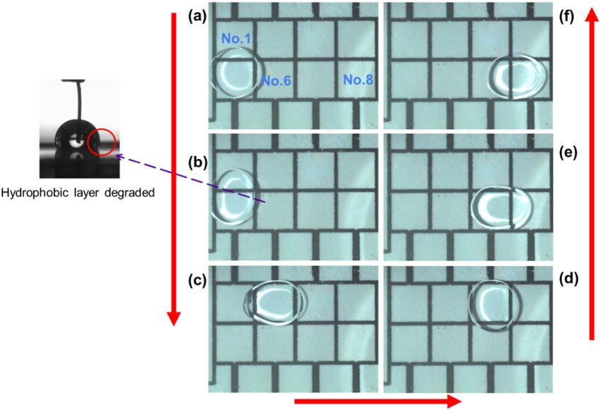
666 Zhijie Luo et al.
Figure 1: EWOD-based droplet driving principle.
In practical experiments, device surface defects such as low-cost portable dynamic droplet sensing system for
dust particles impede droplets from moving to adjacent DMF system applications [24]. This proposed system
energized electrodes. However, the driving control system can monitor the droplet position by using electrical and
will continue to actuate the next electrode, even when the optical methods. Moreover, a feedback mechanism is also
droplet has stopped on the previous electrode. In the pre- implemented in this system.
vious studies, the EWOD chip status was monitored manu- In this study, we propose a driving and feedback
ally, but it should be automated for practical applications. scheme based on machine vision for DMF applications.
Therefore, research teams have proposed few droplet A priority adjustment strategy for driving parameters is
position methods to monitor the droplet status. In a implemented in the proposed scheme. This scheme can
closed-loop EWOD chip control model, the driving con- measure droplet parameters including position, velocity,
trol system has a detection mechanism to sense whether and volume. Furthermore, the EWOD chip status can be
the droplet has completely moved to the energizing elec- obtained by a feedback mechanism. The proposed system
trode before activating the next electrode [14]. is composed of a high-resolution camera, a computer
Capacitive sensing is the commonly used and mature with a graphical image analysis system, and a portable
scheme for locating droplets on EWOD devices [15]. Mul- driving control system. It can achieve precise control of
tiple droplets can be successfully located, and uniform multiple droplets without adding any physical sensors to
size droplets are generated by using this method [16–18]. the EWOD device.
Furthermore, the detection of multiple droplets on a We applied this scheme to (1) show droplet control:
single EWOD device using capacitive-to-digital converter shuttling, (2) control a chemical reaction: two droplets
(CDC) integrated circuit (IC) has been demonstrated by were merged, (3) monitor the EWOD chip status, and
Li et al. [19]. This method is easy to implement and of low (4) demonstrate its feasibility and reliability in stress
cost, but it is time consuming. Especially for complex testing. Furthermore, we present the design details for
EWOD devices, much system memory is required to store the proposed system and believe that this system can
many capacitance values in memory for the analysis. In be useful for researchers studying different chemical
addition, it is difficult to use in EWOD devices with dif- and biomedical applications.
ferent electrode sizes.
The previous studies proposed a droplet position
scheme based on image techniques [20–22]. This method
is implemented by an image processing algorithm, which
extracts the droplet parameter information, including
2 Methods and materials
droplet position [23]. Compared with capacitive-based
sensing methods, its advantages are high efficiency and 2.1 EWOD device structure and materials
accuracy. However, machine vision-based methods are
costly and difficult to develop. Most studies do not The EWOD device comprises an electrode array of photo-
include the priority analysis or a driving parameter feed- lithography patterned metal (indium tin oxide) on a glass
back model. Recently, Jain and Patrikar demonstrated a substrate with a ground plane (indium tin oxide on glass)
Machine vision-based driving and feedback scheme 667
connected parallel to it. The electrode array and the resolution camera, a computer with a graphical image ana-
ground plane are separated by a gasket of known thick- lysis system, and the driving control system.
ness (H). Some individual droplets are contained between There are four key modules in the design of the
the electrode array and the ground plane. To reduce fric- EWOD chip machine vision-based driving and feedback
tion, silicone oil (mass fraction: 10%) was used as the scheme: image acquisition, image processing and recog-
lubricant surrounding the droplets in previous studies. nition, chip status analysis, and feedback and driving.
A hydrophobic insulating layer is spin coated to insu- The original EWOD chip image, including droplets, cap-
late the droplets from the electrode array. In our study, tured by the camera must be processed through an image
Teflon AF 1600 (800 nm) is used as a dielectric as well as algorithm. The complete image processing and the ana-
a hydrophobic layer in the EWOD device. Note that the lysis solution are shown in Figure 4. The background of
Teflon AF 1600 is a biocompatible polymer with an the EWOD chip and the droplet shapes have obvious dif-
average static contact angle of 116°. Its dielectric constant ferences. Background subtraction and droplet extraction
is approximately 2.4. This characteristic is conducive are the two main algorithms used in our study to capture
to various droplet operations [25]. The top view of a the real-time position of droplets on the EWOD chip.
closed EWOD chip is shown in Figure 2(a). It consists of First, the K-nearest neighbor (KNN) background model
10 (3 mm × 3 mm) square electrodes with a 50 μm separa- of the original image is built by the image analysis system.
tion between adjacent electrodes. The height between the Then, we use morphology to analyze the processed images
upper plate and the lower plate is approximately 1.5 mm. and set appropriate “expansion” parameters. We also develop
To ensure the stability of the EWOD chip and the reliability a median-based Gaussian weighted filter (MGWF) that is
of the circuit connection, we designed a printed circuit effective for image edge filtering. To eliminate salt-and-
board (PCB) foil as the interface between the EWOD chip pepper noise, an improved adaptive filtering (IAMF) algo-
and the external driver circuit. Each electrode is connected rithm is used in this study. Finally, the positions of droplets
to an external driving chip interface by a separate electrical are recognized by a circular edge detection algorithm.
wire. The spacing between the adjacent electrical wires is The proposed driving control system is programmed to
1 mm. Detailed parameters and dimensions of the PCB foil control a series of droplet actuations and acquire image
are shown in Figure 2(b). information from the image analysis system to manage the
control logic for the sequential operations. Different droplet
operations (e.g., move, dispense, merge) can be automati-
cally controlled based on the recognition and feedback.
2.2 Machine vision-based driving and
feedback scheme
Figure 3 shows a schematic illustration of the machine 2.3 Driving control system
vision-based DMF driving and feedback scheme in a
double-plate EWOD chip configuration. The four major The EWOD device driving control system architecture
components include the double-plate EWOD chip, a high- diagram is shown in Figure 5. We use an embedded
Figure 2: (a) Top view of the closed EWOD chip. (b) Detailed parameters and dimensions of the PCB foil.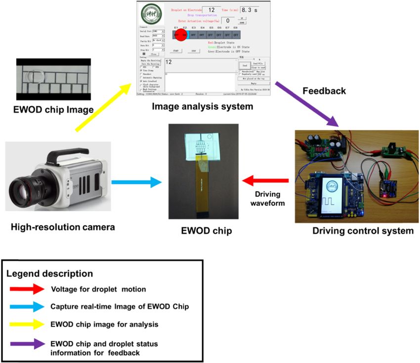
668 Zhijie Luo et al. Figure 3: A schematic illustration of the EWOD chip machine vision-based driving and feedback scheme. microcontroller (STM32F7) as the control core of the 2.4 Feedback model for droplet actuation driving control system. Its frequency can reach 180 MHz, and it has abundant communication interfaces (i.e., SPI, As described earlier, the real-time positions of droplets I2C, and a serial port). To actuate the droplet from one on the EWOD chip can be obtained by the proposed loca- electrode to another electrode, a high voltage signal is tion system. Furthermore, the droplet position data are necessary. Most previous studies used a “boost converter provided to the driving control system as feedback. + relay” as the voltage output module. However, the pro- In this study, we present a priority adjustment strategy blem with this design is that the voltage rise time is high for driving parameters based on feedback (Table 1). The (e.g., 200–500 ms). To avoid this problem, an SSD1627 chip criterion of the proposed feedback model is to improve is used as a voltage output module in the proposed driving DMF application efficiency without affecting the EWOD control system. It has 98 I/O ports, each of which can work chip stability as much as possible. together or independently and output 18–40 V of driving For the proposed system, users must enter values voltage [26]. These characteristics can meet the driving for parameters required to actuate the droplets on the requirements of EWOD devices very well. All the real- device before the system starts. These parameters time data are stored in an external electrically erasable pro- mainly include electrode radius, droplet radius (i.e., grammable read-only memory (EEPROM; 32 kB, M95320-R, one and a half of the electrode size), initial single STMicroelectronics). The serial port is used as a data driving time (i.e., time duration for one pulse), incre- exchange interface between the image analysis system and mental time (i.e., time duration for one adjustment), the driving control system. The proposed driving control initial driving voltage (i.e., initial voltage applied to the system has the advantages of easy fabrication, portability, electrode), incremental voltage, initial electrode, and des- and a high level of integration. tination electrode.
Machine vision-based driving and feedback scheme 669
Figure 5: Driving control system architecture diagram.
Table 1: Priority adjustment strategy for driving parameters based
on feedback
Figure 4: The complete image processing and analysis solution.
Driving parameters Priority
To ensure the reliability and safety of the EWOD chip, Single driving time 1 (top)
the highest driving parameter adjustment priority is given to Driving voltage 2
the single driving time. Generally, for most DMF applica- Droplet motion path 3
tions, the single drive time is less than 2,000 ms. A change
in the driving time will not affect the EWOD chip reliability.
Droplet operations (e.g., moving or splitting) are the droplet motion path. For soluble droplets, the motion
highly dependent on driving voltage. Due to various path recalculation for a particular droplet must consider the
defects on the electrode surface, a larger driving voltage motion paths of all droplets (i.e., at least two electrodes
is beneficial to overcome the resistance to droplet move- should separate the droplets). This requires that the control
ment. However, excessive driving voltage may cause system not only have accurate droplet positioning cap-
degradation of the dielectric layer, reducing the lifetime ability but also have powerful calculation and analysis
of EWOD device. Consequently, it takes second priority. It ability. In our software, the shortest path method is used
should be noted that the incremental voltage should not to recalculate the new droplet motion path.
be set too large in most applications. In our study, it was The feedback control pseudo code is presented in
set to 2 V. Table 2. The software used in this article is written in
In this study, we first proposed the droplet motion the standard C/C++ language. By using the modular
path as a modifiable parameter in the feedback model. design, the efficiency, expansibility, and maintainability
The droplet motion path has the lowest priority. Generally, of the software are improved. The driving voltage and time
the default droplet motion path is the optimal path. Some are accumulated based on cyclic iteration in the proposed
experiments revealed that there can be droplet motion system. Because the voltage rise time of the SSD1627 chip is
failure even if the driving voltage and time are sufficiently approximately 10 ms, the modification of driving para-
large. In this case, the driving control system must adjust meters for droplet control can occur quickly.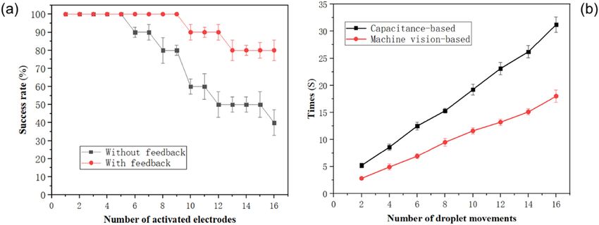
670 Zhijie Luo et al.
Table 2: Feedback control pseudo code 3 Results and discussion
Main program (): Adjustment of driving
parameters (): 3.1 Droplet location experiment
System_Start (); Voltage = default
The image analysis system is programmed based on the
System_Init (); Time = default
N = 0; Voltage_ increase = default OpenCV library, which is used to develop and verify the
While (1) Time_ increase = default proposed detection and recognition scheme in the Visual
{ Voltage_Max = default Studio (VS) 2015 environment.
Electrode_ Activation(N); Time_Max = default First, we set up a droplet location experiment to
P = Check_Droplet_Postition (); If (Time < Time_Max)
demonstrate the proposed system’s algorithm flow. To
If (P = = fail) {
{ Time = Time + Time_
detect the droplet position, four operations were exe-
increase; cuted every 300 ms to judge whether the droplet had
Adjustment of driving Return; dispensed from the reservoir electrode or transferred suc-
parameters (); cessfully over the activated electrode. The algorithm flow
Electrode_ Activation(N); } of the machine vision-based driving and the feedback
} If (V < Voltage_Max)
system is shown in Figure 6.
Else (P = = success) {
{ Voltage = Voltage + Voltage_ Step 1: The image analysis system acquires an ori-
increase; ginal frame captured by the high-resolution camera.
N = N + 1; Return; Step 2: The image analysis system calculates a difference
} } image for the droplet by subtracting a reference image.
} Droplet_Motion_Path ();
Step 3: The image analysis system binarizes the differ-
Return;
}
ence image using a series of image algorithms. Step 4:
The image system uses a Hough transform function to
detect droplets on electrodes. Step 5: The image analysis
system returns a successful or unsuccessful result to
Ethical approval: The conducted research is not related to the driving control system. A failed droplet motion will
either human or animal use. trigger driving parameter adjustment (as presented in
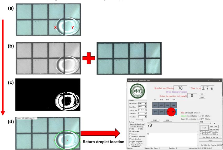
Figure 6: Algorithm flow of the machine vision-based driving and feedback system. (a) Original image of EWOD device. (b) Image graying
and background extraction. (c) Image binaryzation. (d) Droplet location.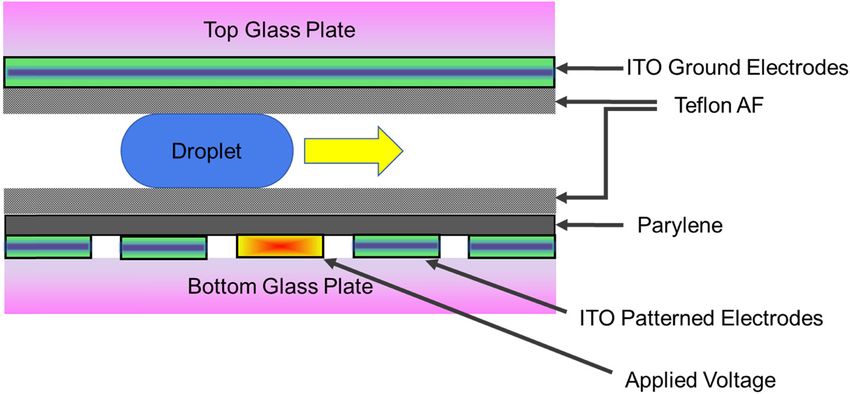
Machine vision-based driving and feedback scheme 671
Figure 7: The comparison results of the two droplet motion methods. (a) Success rate of droplets shuttled under different driving schemes.
(b) The time of droplet movements under different control schemes.
Table 1, there are three priorities) until the motion is machine vision-based driving and feedback scheme. The
successful. If the droplet successfully moved to the target purpose of this experiment is to demonstrate the effect of
electrode, it will be driven to the next electrode based on the proposed scheme on the success rate of continuous
the default droplet path. These procedures are designed droplet motion. Shuttling means that the droplet moves
to set up a closed loop, so that droplet detection and back and forth frequently in the EWOD chip. In this experi-
driving are executed continuously and simultaneously. ment, a droplet shuttled in a linear EWOD chip consisting of
In this instance, a droplet was stationary at the x eight electrodes. The electrode diameter is 5 mm, and their
electrode. The driving control system activated the y elec- spacing is 20 µm. The number of activated electrodes ranges
trode. An original frame was captured by the high-reso- from 1 to 16. Each case was repeated 10 times.
lution camera, as shown in Figure 6(a). A grayscale frame From the experimental result shown in Figure 7(a),
was obtained from the original frame (Figure 6(b)). In our we can see that the success rate of droplet shuttling
study, a reference image of the EWOD chip was acquired decreases with the increasing number of activated elec-
without visible droplets on any of the electrodes. This trodes without a feedback scheme. When the number of
reference image is acquired for droplet edge detection activated electrodes was 16, the success rate was only
and droplet position subtraction techniques. Further- 40%. The reason for the failure is that the droplet was
more, a binary frame is created using image-processing blocked on electrode No. 6. A larger driving time and
algorithms. From this frame, a Hough transform function voltage can be set to overcome this problem. However,
can be used to detect circles (droplets), as shown in such a configuration will not only affect the real-time
Figure 6(d). performance of the DMF system but also reduce the sta-
After sensing the droplet’s position, the feedback bility of the EWOD device (the larger voltage will reduce
model is applied to ensure that droplets can reach the the life of the hydrophobic layer). To solve this issue, the
target electrode smoothly. As described earlier, the system proposed driving and feedback scheme is integrated with
will first adjust the single driving time if the droplet motion the DMF system. The experimental result shows that the
has failed. proposed scheme can effectively improve the success rate
of droplet shuttling (i.e., the success rate can reach at
least 80% with feedback). Furthermore, the proposed
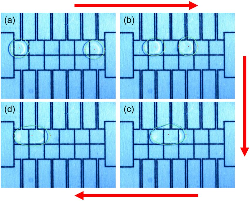
3.2 Droplet motion experiment: shuttling scheme can be applied to several DMF system droplet
operations, including splitting, dispensing, and merging.
Surface defects on a hydrophobic layer may cause unsteady In addition, we conducted a comparison between the
motion. If droplet motion is unexpectedly slowed, sequen- capacitance-based position method and the proposed
tial electrode activation without feedback will result in an scheme. Figure 7(b) shows the comparison results of the dro-
out-of-control droplet. In this section, droplet shuttling was plet motion under different control schemes. As mentioned
selected as a verification experiment for demonstrating the earlier, compared with conventional capacitance-based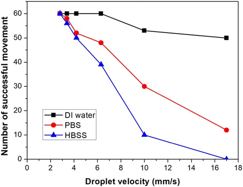
672 Zhijie Luo et al.
Figure 8: A chemical reaction controlled by the proposed system. (a) Two droplets of equal volume (D-glucose and H2O) are observed on the
EWOD chip. (b) The two droplets are driven toward the middle electrode. (c) The two droplets merge on the EWOD chip. (d) The merged large
droplet is captured by the proposed system and moved to the left electrode.
sensing methods, the advantage of the machine vision- Moreover, this method cannot identify the size of the
based position method is high efficiency. With an increased merged droplet.
number of droplet movements, the detection time required In this section, a universal chemical reaction (the
by capacitance-based sensing methods is much longer than droplet on the left is D-glucose, the one on the right is
that for the machine vision-based position method. This is H2O) is controlled and detected by the proposed scheme
because the capacitance-based position method must col- on the EWOD chip. The aim of this study is to observe the
lect the capacitance values of all electrodes every time. For proposed system’s performance as the droplet volume
EWOD chips with many electrodes, the locating time will far changes. As shown in Figure 8(a), two droplets of equal
exceed the droplet movement time. volume (3 μL) are captured by the proposed system. Two
droplets are driven to move toward the middle region
simultaneously (as shown in Figure 8(b)). The mole
3.3 Droplet motion experiment: merging values were converted to the number of molecules in
6 μL, which is the volume of the merged droplet. After
Next, we used the proposed scheme to track droplets the two droplets containing chemicals were merged (as
merging on the EWOD chip. Droplet merging is a com- shown in Figure 8(c)), the system deduced that the
monly performed operation on EWOD chips. Merging is merged droplet volume is approximately 6.3 μL by ana-
defined as an operation in which multiple droplets are lysis and calculation. The experimental results show that
driven to an electrode for fusion, and the merged large the measured droplet volume agrees with the theoretical
droplet can move successfully. This operation is widely droplet volume.
used in chemical and biological fields. Some previous After this experiment, we found that the driving control
studies detected droplet merging by capacitive sensing system applied 30 V to drive the merged droplet at the
and feedback [27,28]. However, this method is time beginning, but failed. According to the feedback model,
consuming because it needs to scan every electrode. the driving control system adjusted the driving parameters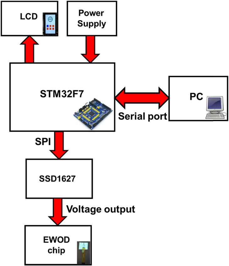
Machine vision-based driving and feedback scheme 673
We know that Td not only affects the droplet movement
success rate but also determines droplet velocity. In this
experiment, different liquids, DI water, PBS, and HBSS
were driven across six electrodes at different velocities
(i.e., different single driving times: 300, 500, 800, 1,200,
1,500, and 1,800 ms) with 10 repetitions for a total of 60
actuations. Figure 9 shows that DI water maintains a higher
motion performance at high velocities (short single driving
time). However, higher velocities generally result in poor
droplet movement for liquids containing NaCl (PBS and
HBSS). Although a longer single driving time can improve
the droplet movement success rate, it may aggravate surface
fouling of the hydrophobic layer [29] and reduce the real
time of the system. This experiment shows that it is not
appropriate to use a fixed single driving time to drive dro-
Figure 9: The droplet movement performance for different liquids on plets. Therefore, the feedback model has good application
the EWOD chip without feedback.
significance for a DMF system.
The droplet movement performances for different
many times (i.e., the driving voltage reached 40 V) until the liquids on the EWOD chip with feedback are shown in
merged droplet moved successfully (Figure 8(d)). Table 3. Obviously, improvements are observed in this
Of note, droplet motion can accelerate the rate of experiment. The number of successful movements (out
a chemical reaction, similar to shaking a test tube to of 60) increased significantly with the proposed scheme
increase the chemical reaction rate. This is an advantage for the same droplet velocity. Particularly in complex
of the DMF system in chemical and biological fields. DMF systems (i.e., multiple droplets moving simulta-
neously on the EWOD chip), droplet velocity should be
taken into account. In addition, in this experiment, we
found that a short driving time (300 ms) is favorable for
3.4 Droplet status detection liquids containing no proteins (PBS and DI water), while
a long driving time (1,200 ms) is favorable for protein-rich
In addition to droplet shuttling and merging, we also
liquids (HBSS). This observation is similar to that of the
validated the proposed scheme by evaluating droplet
previous study [30], where a short single driving time was
movement effects for different liquids. All of them (i.e.,
not enough to account for the liquid viscosity.
DI water, PBS, and HBSS) are commonly used in chemical
If the droplet is conductive and the driving voltage is
and biological experiments. In our experiment, different
DC, the actuation force in the absence of a top dielectric
liquids were driven across a linear EWOD chip consisting
layer depends on the equivalent capacitance of the bottom
of six electrodes; this was repeated 10 times for a total of
dielectric layer [31]. On the same EWOD device, the dro-
60 motions.
plet motion performance will depend on the friction
In general, the droplet velocity was measured for
force. Also, the higher friction forces is associated with
each movement. It is the ratio between the electrode
high-viscosity liquids [32]. The pH of the droplet has no
length (L; i.e., L = 5 mm) and the single driving time
direct effect on the droplet movement performance.
(Td; i.e., V = L/Td) without a feedback system. However,
for the proposed scheme, the image analysis system
needs some time to locate the droplets. This time (Tp) is
approximately 200 ms (±50). Moreover, the driving chip Table 3: The performance of different liquids on the EWOD chip with
(Tv) output time is approximately 20 ms. Hence, the dro- feedback
L×N
plet velocity was defined as V = Kd × (Td + Tp + Tv )
, where Kd is
Liquid type Number of successful Average velocity
the number of electrode actuations and N is the number
movements (mm/s)
of electrodes that the droplet actually crosses in the
experiment. DI water 60 10.2
PBS 60 6.9
The droplet movement performance for different liquids
HBSS 60 5.2
on the EWOD chip without feedback is shown in Figure 9.674 Zhijie Luo et al.
Table 4: Specific experimental parameters of the adaptive an adaptive experiment. The specific experimental para-
experiment meters are presented in Table 4. The initial driving vol-
tage and single driving time are 0. In this experiment, we
Experimental parameters Value artificially burned the hydrophobic layer of electrode No.
Initial driving voltage 0V 6 using high voltage (100 V). The whole experiment is
Initial single driving time 0 ms automatically controlled by the proposed system. A series
Initial electrode No. 5 of experimental images is shown in Figure 10.
Destination electrode No. 8
After this experiment, we printed out and reviewed
Damaged electrode No. 6
Electrode dimension 5 mm
all the system records. First, the system calculated the
Droplet radius 3.5 mm droplet motion path (i.e., the shortest path method:
No. 5 → 6 → 7 → 8). Next, the system activated the
No. 6 electrode according to the droplet motion path.
Clearly, the experimental data generated by the pro- However, the droplet could not pass over the No. 6 elec-
posed feedback model much better estimated the actual trode because it had been damaged (this process lasted
kinetics than those generated without feedback control. approximately 9 s). During this process, the driving vol-
Hence, this experiment proved that the proposed driving tage and single driving time were adjusted many times
and feedback scheme helps improve the motion perfor- (i.e., the voltage reached 40 V and the time reached
mance of liquids containing NaCl by automatically opti- 1,800 ms). In this condition, the system recalculated
mizing the driving parameters. the droplet motion path (i.e., new path: No. 5 → 1 → 2
→ 3 → 7 → 8). Finally, the droplet successfully moved to
the destination electrode (No. 8). Table 5 presents the
number of driving parameter modifications in this experi-
3.5 Adaptive experiment ment. The driving time was modified 18 times. The results
are consistent with our feedback model presented in
There are inevitably various failures in practical DMF Table 1. Notably, the increment of driving voltage (3 V)
applications. To demonstrate the reliability of the pro- and time (300 ms) were set relatively low in this experi-
posed scheme in complex DMF applications, we set up ment. Such a setup is beneficial to protect the EWOD
Figure 10: A series of real-time EWOD chip images. All driving parameters are set and adjusted adaptively by the proposed system.
(a) Droplet stays at No. 5 electrode. (b–e) Droplet changes motion path. (f) Droplet reaches the destination electrode.Machine vision-based driving and feedback scheme 675
Micro and nano. 2020;24(8):1–9
Table 5: The number of driving parameter modifications
Appl Phys Lett. 2013;102:193513
Lab on a chip. 2017;17:3437–46
Bioengineering. 2017;4:45–61
Driving parameters Number of modifications
Single driving time 18
Driving voltage 10
Droplet motion path 1
Reference
Our work
chip. However, it will affect the DMF system efficiency.
Specific feedback model rules can be fine-tuned for dif-
ferent applications (e.g., increment or driving voltage
range).
Portability and
Electrode damage is a kind of device defect that cannot
integration
be repaired. In this experiment, the proposed system suc-
Medium
cessfully transported the droplet to the target electrode by
High
High
High
Low
modifying the droplet’s motion path. Furthermore, the
system will record the electrode number and the newest
droplet motion path. The droplet will not become stuck on
Multiple parameters
Multiple parameters
the damaged electrode again the next time. The experi-
Preparation before
mental results revealed that the proposed mechanism has
good reliability and ability to avoid interference (i.e., a detection
damaged electrode).
Medium
Simple
Simple
The properties comparison of the proposed scheme
with some previously reported control system is summa-
rized in Table 6. The position sensing of the proposed
scheme is dynamic, indicating detection, feedback, and
actuation can be simultaneously realized. The driving
control system has high portability and integration.
Table 6: The comparison of some previous DMF control systems and proposed scheme
recalculation
Motion path
Moreover, the preparation of the proposed system before
detection is simple. The properties of self-adaptive of
Yes
Yes
No
No
No
actuation parameters and recalculation of droplet motion
path are also very useful for practical applications of the
DMF system.
Machine vision based
Machine vision based
Machine vision based
Electrical impedance
Capacitance based
Position method
4 Conclusion
based
In this article, we demonstrate a driving and feedback
scheme based on machine vision for a DMF system.
This scheme consists of three main parts: a high-resolu-
schemes
Dynamic
Dynamic
Dynamic
Dynamic
tion camera, a computer with a graphical image analysis
Sensing
Static
system, and a portable driving control system. A refer-
ence and subtracting technique with a Hough transform
is used in the proposed image analysis system to locate
Imaged based feedback
multiple droplets on the EWOD chip. The experimental
Proposed system
results show that the proposed system can accurately
System name
locate multiple droplets in real time. Furthermore, a feed-
OpenDrop
back model is implemented in the proposed system,
DropBot
ISPSAA
system
which is capable of detecting individual droplets merg-
ing and motion failures. It can effectively improve the676 Zhijie Luo et al.
success rate of different droplet controls and operations. [5] Guttenberg Z, Müller H, Habermüller H, Geisbauer A, Pipper J,
To show the adaptability of proposed scheme, we applied Felbel J, et al. Planar chip device for PCR and hybridization with
it to the EWOD chip with a damaged electrode without surface acoustic wave pump. Lab Chip. 2005;5(3):308–17.
doi: 10.1039/B412712A.
any external sensors. The proposed scheme provides a
[6] Latorre L, Kim J, Lee J, de Guzman PP, Lee HJ, Nouet P, et al.
robust, high-precision, and intelligent solution for com- Electrostatic actuation of microscale liquid-metal droplets.
plex droplet control with performance that exceeds both J Microelectromech. 2002;11(4):302–8. doi: 10.1109/
manually operated and previously reported automated JMEMS.2002.800934.
DMF control systems. We expect that the proposed scheme [7] Lee J, Moon H, Fowler J, Schoellhammerc T, Kim CJ.
Electrowetting and electrowetting-on-dielectric for microscale
will be useful for scientists developing automated analysis
liquid handling. Sensor Actuat A Phys. 2002;95(2–3):259–68.
platforms for a wide range of DMF system applications. doi: 10.1016/S0924-4247(01)00734-8.
[8] Chatterjee D, Shepherd H, Garrell RL. Electromechanical model
Acknowledgments: We thank AiQing Huang and ZhongYu for actuating liquids in a two-plate droplet microfluidic device.
Pan for their initial work with the automation control Lab Chip. 2009;9(9):1219–29. doi: 10.1039/b901375j.
[9] Mathwig K, Aartsma TJ, Canters GW, Lemay SG. Annual review
system.
of analytical chemistry. Annu Rev Anal Chem.
2015;7(1):383–405. doi: 10.1146/annurev-anchem-062012-
Funding information: This work was financially supported 092557.
by the National Natural Science Foundation of China [10] Schertzer MJ, Ben-Mrad R, Sullivan PE. Using capacitance
(61871475), the Guangdong Science and Technology Plan measurements in EWOD devices to identify fluid composition
(201905010006), the Foundation for High-level Talents in and control droplet mixing. Sensor Actuat B Chem.
2010;145(1):340–7. doi: 10.1016/j.snb.2009.12.019.
Higher Education of Guangdong Province (2017KQNCX097;
[11] Guan Y, Tong AY. A numerical study of microfluidic droplet
2018LM2168), and the Guangzhou Science Research Plan transport in a parallel-plate electrowetting-on-dielectric
(201904010233). (EWOD) device. Microfluid Nanofluid. 2015;19(6):1477–95.
doi: 10.1007/s10404-015-1662-5.
Author contributions: Z. L.: writing – original draft; Z. L. [12] Ahmadi F, Samlali K, Vo PQN, Shih SCC. An integrated droplet-
and L. W.: investigation; J. X.: software; B. H.: validation; digital microfluidic system for on-demand droplet creation,
mixing, incubation, and sorting. Lab Chip. 2019;19(4):524–35.
Z. H.: data curation; L. C.: writing – review and editing;
doi: 10.1039/C8LC01170B.
S. L.: formal analysis; S. L.: resources. [13] Murran MA, Najjaran H. Capacitance-based droplet position
estimator for digital microfluidic devices. Lab Chip.
Conflict of interest: The authors state no conflict of 2012;12(11):2053–9. doi: 10.1039/c2lc21241b.
interest. [14] Gao J, Liu XM, Chen TL, Mak PI, Du YG, Vai MI, et al. An intel-
ligent digital microfluidic system with fuzzy-enhanced feed-
back for multi-droplet manipulation. Lab Chip.
Data availability statement: The datasets generated 2013;13(3):443–51. doi: 10.1039/c2lc41156c.
during and/or analyzed during the current study are [15] Elbuken C, Glawdel T, Chan D, Ren CL. Detection of microdro-
available from the corresponding author on reasonable plet size and speed using capacitive sensors. Sensor Actuat A
request. Phys. 2011;171(2):55–62. doi: 10.1016/j.sna.2011.07.007.
[16] Jebrail MJ, Bartsch MS, Patel KD. Digital microfluidics: a ver-
satile tool for applications in chemistry, biology and medicine.
Lab Chip. 2012;12(14):2452–63. doi: 10.1039/c2lc40318h.
[17] Su F, Ozev S, Chakrabarty K. Concurrent testing of digital
References microfluidics-based biochips. ACM Trans Des Automat El.
2006;11(2):442–64. doi: 10.1145/1142155.1142164.
[1] Dittrich PS, Manz A. Lab-on-a-chip: microfluidics in drug dis- [18] Demori M, Ferrari V, Poesio P, Strazza D. A microfluidic capa-
covery. Nat Rev Drug Discov. 2006;5(3):210–8. doi: 10.1038/ citance sensor for fluid discrimination and characterization.
nrd1985. Sensor Actuat A Phys. 2012;172(1):212–9. doi: 10.1016/
[2] Haeberle S, Zengerle R. Microfluidic platforms for lab-on-a- j.sna.2011.07.013.
chip applications. Lab Chip. 2007;7(9):1094–110. [19] Li Y, Li H, Baker RJ. A low-cost and high-resolution droplet
doi: 10.1007/978-3-642-18293-8_22S. position detector for an intelligent electrowetting on dielectric
[3] Fair RB, Khlystov A, Tailor TD, Ivanov V, Evans R, Griffin P, et al. device. J Lab Autom. 2015;20(6):1–7. doi: 10.1177/
Chemical and biological applications of digital-microfluidic 2211068214566940.
devices. Des Test Comput. 2007;24(1):10–24. doi: 10.1109/ [20] Shin YJ, Lee JB. Machine vision for digital microfluidics. Rev Sci
MDT.2007.8. Instrum. 2010;81(1):014302. doi: 10.1063/1.3274673.
[4] Sammarco TS, Burns MA. Thermocapillary pumping of discrete [21] Vo PQN, Husser MC, Ahmadi F, Sinha H, Shih SCC. Image-
drops in microfabricated analysis devices. AICHE J. based feedback and analysis system for digital microfluidics.
2010;45(2):350–66. doi: 10.1002/aic.690450215. Lab Chip. 2017;17(20):3437–46. doi: 10.1039/C7LC00826K.Machine vision-based driving and feedback scheme 677
[22] Sotiropoulou CL, Voudouris L, Gentsos C, Demiris AM, fluidics systems: From dynamic saturation to device physics.
Vassiliadis N, Nikolaidis S. Real-time machine vision FPGA Micromachines (Basel). 2015;6(6):778–89. doi: info:doi/
implementation for microfluidic monitoring on lab-on-chips. 10.3390/mi6060778.
IEEE Trans Biomed Circ Syst. 2014;8(2):268–77. doi: 10.1109/ [28] Lee SH, Lee IH, Kim J, Keum CM, Yu ES, Lee SD. Electrowetting-
TBCAS.2013.2260338. on-dielectric device controlled by embedded undulating
[23] Sohail S, Biswas K. Dynamic sensing of liquid droplet in electrode for liquid transport. J Nanosci Nanotechnol.
electrowetting devices. Sensor Lett. 2015;13(9):721–34. 2016;16(6):6455–8. doi: info:doi/10.1166/jnn.2016.12126.
doi: info:doi/10.1166/sl.2015.3521. [29] Phongsomboon C, Sukhthang K, Wechsatol W, Tuantranont A,
[24] Jain V, Patrikar RM. A low-cost portable dynamic droplet sen- Lomas T. Droplet movement on a low cost EWOD
sing system for digital microfluidics applications. IEEE Trans according to applied frequencies and voltages. Appl Mech
Instrum Meas. 2019;PP(99):1–1. doi: 10.1109/ Mater. 2011;87:140–5. doi: 10.4028/www.scientific.net/
TIM.2019.2932526. AMM.87.140.
[25] Jain V, Hole A, Deshmukh R, Patrikar R. Dynamic capacitive [30] Ng AHC, Dean Chamberlain M, Situ H, Lee V, Wheeler AR.
sensing of droplet parameters in a low-cost open EWOD Digital microfluidic immunocytochemistry in single cells.
system. Sensor Actuat A Phys. 2017;263:224–33. doi: 10.1016/ Nat Commun. 2015;6:7513. doi: 10.1038/ncomms8513.
j.sna.2017.06.014. [31] Bahadur V, Garimella SV. Energy minimization-based analysis
[26] Luo ZJ, Zhang WN, Liu LW, Xie ST, Zhou GF. Portable multi-gray of electrowetting for microelectronics cooling applications.
scale video playing scheme for high-performance electrowet- Microelectron J. 2008;39(7):957–65. doi: 10.1016/
ting displays. J Soc Inf Display. 2016;24(6):109–19. j.mejo.2007.11.010.
doi: 10.1002/jsid.444. [32] Shih SCC, Fobel R, Kumar P, Wheeler AR. A feedback control
[27] Cui WW, Zhang ML, Duan XX, Pang W, Zhang DH, Zhang H. system for high-fidelity digital microfluidics. Lab Chip.
Dynamics of electrowetting droplet motion in digital micro- 2010;11(3):535–40. doi: 10.1039/c0lc00223b.You can also read