Development of Self-Diagnosis Tests System Using a DSL for Creating New Test Suites for Integration in a Cyber-Physical System
←
→
Page content transcription
If your browser does not render page correctly, please read the page content below
Development of Self-Diagnosis Tests System Using
a DSL for Creating New Test Suites for Integration
in a Cyber-Physical System
Ricardo B. Pereira         #
Department of Informatics, University of Minho, Braga, Portugal

José C. Ramalho         #
Centro Algoritmi (CAlg-CTC), Department of Informatics, University of Minho, Braga, Portugal

Miguel A. Brito        #
Centro Algoritmi, Department of Information Systems, University of Minho, Guimarães, Portugal

      Abstract
Testing Cyber-physical systems (CPS) requires highly qualified engineers to design the tests since
its computational part is programmed in low-level languages. The origin of this work arises from
the need to find a solution that optimizes this problem and allows abstracting the current methods
so that the tests can be created and executed more efficiently. We intend to do this by creating a
self-diagnosis tests system that allows us to automate some of the current processes in the creation
and execution of test suites. The work presented here addresses the problem by creating a new
self-diagnosis tests system that will guarantee the reliability and integrity of the CPS. In detail, this
paper begins by exposing a study on the current state of the art of test automation, Keyword-driven
Testing (KDT) methodology and Domain-specific Languages (DSL). A new modular and extensible
architecture is proposed for self-diagnosis tests systems based on two main concepts: the creation
of a DSL combined with the use of the KDT methodology, as well as a methodology to extend it
and integrate it into a CPS. A new self-diagnosis tests system has been proposed that applies the
proposed architecture proving that it is possible to carry out the self-diagnosis in real-time of the
CPS and allowing the integration of any type of test. To validate the implementation of the system,
28 test cases were carried out to cover all its functionalities. The results show that all test cases
passed and, therefore, the system meets all the proposed objectives.

2012 ACM Subject Classification Software and its engineering → Parsers; Computer systems
organization → Embedded and cyber-physical systems; Information systems → RESTful web
services

Keywords and phrases Web Application, DSL, Self-diagnosis, Test automation, Cyber-physical
systems

Digital Object Identifier 10.4230/OASIcs.SLATE.2021.19

 1      Introduction

Today, the production of many industrial companies is supported by cyber-physical systems
(CPS) and, therefore, they must be able to obtain the maximum performance of these
systems. For this, it is necessary that these systems remain reliable and can guarantee their
functionality [9]. However, to ensure that these systems work correctly, a diagnosis of them
is necessary regularly. Testing CPS requires highly qualified engineers to design the tests
since its computational part is programmed in low-level languages. The origin of this work
arises from the need to find a solution that optimizes this problem and allows abstracting the
current methods so that the tests can be created and executed more efficiently. We intend
to do this by creating a self-diagnosis tests system that allows us to automate some of the
current processes in the creation and execution of test suites.
             © Ricardo B. Pereira, José C. Ramalho, and Miguel A. Brito;
             licensed under Creative Commons License CC-BY 4.0
10th Symposium on Languages, Applications and Technologies (SLATE 2021).
Editors: Ricardo Queirós, Mário Pinto, Alberto Simões, Filipe Portela, and Maria João Pereira; Article No. 19;
pp. 19:1–19:16
                     OpenAccess Series in Informatics
                     Schloss Dagstuhl – Leibniz-Zentrum für Informatik, Dagstuhl Publishing, Germany
19:2 Self-Diagnosis Tests System Using a DSL for Creating New Test Suites
The work presented here addresses the problem by creating a new self-diagnosis tests
system that will guarantee the reliability and integrity of the CPS. In detail, this paper
begins by exposing a study on the current state of the art of test automation, Keyword-
driven Testing (KDT) methodology and Domain-specific Languages (DSL). A new modular
and extensible architecture is proposed for self-diagnosis tests systems based on two main
concepts: the creation of a DSL combined with the use of the KDT methodology, as well as
a methodology to extend it and integrate it into a CPS. A new system of self-diagnosis tests
system has been proposed that applies the proposed architecture and aims to prove that it is
possible to perform the self-diagnosis in real-time of the CPS and allow the integration of
any type of test through the combination of a DSL with the KDT methodology. Some test
cases were also carried out to validate the implemented solution.
Section 2 analyzes the state of the art in test automation, KDT methodology and DSL.
Section 3 describes the structure and architecture of the system. Section 4 describes the
implementation of the system. Finally, Section 5 concludes and identifies future work.
2 State of the art
In this section, a review of the state of the art in test automation will be presented in
Section 2.1. In Section 2.2, KDT methodolody is presented as well as the advantages and
disadvantages of using it. In Section 2.3, a brief introduction is made to the concept of
DSL and, more specifically, how to apply this concept with the Another Tool for Language
Recognition (ANTLR).
2.1 Test Automation
The importance of testing automation is directly related to the quality of the final product.
The execution of all functional tests before delivery guarantees the lowest incidence of errors
in the post-delivery of the final product. As such, software developers/creators are required
that their projects maintain a certain quality standard during all phases of development
until the launch of a new product. Therefore, testing at the end of each stage no longer
works in a professional environment. This is because the occurrence/discovery of unforeseen
obstacles can significantly delay the development of the software. In recent years, it has been
found that the software development market has increased its competitiveness, due to the
modernization of the technologies involved and due to the maturity of the capacity to develop
software. Thus, the range of information technology solutions, to meet the needs of consumer
organizations, has increased considerably, which ends up making it difficult for users to
choose when purchasing a product. In this competitive scenario, consumer organizations,
when opting for software, are increasingly relying on quality criteria. One of the pillars for
ensuring this quality of the software product is the testing process [1].
In the current software market, the concern for creating quality and error-free products
has led companies to look for models and processes that guarantee quality to satisfy the needs
of their customers. Unsuccessful projects, with expired deadlines and defective products, lead
to customer dissatisfaction, high maintenance costs and compromise the company’s image.
The main objective of a software test is to define the implementation of this software that
meets all the specifications and expectations defined and expected by the customer, that is,
the objective is to “verify” if what was specified in the requirements phase is what really
was developed. When verifying that the implemented software meets all specifications and
expectations defined and expected by the customer, it also looks for errors in the software.
The software test must be seen as a part of its quality process.R. B. Pereira, J. C. Ramalho, and M. A. Brito 19:3
Test automation is not limited to just performing the tests but above all being aware of
when and where the tests need to be carried out, thus leaving the test team more time to
plan more effective tests with better quality accuracy instead of worrying about scheduling
them. Thus, automation results in the mechanization of the entire process of monitoring and
managing the needs for testing and evaluation associated with software development [3].
2.2 Keyword-Driven Testing
KDT is a type of functional automation testing methodology that is also known as table-
oriented testing or action-based testing. In KDT, we use a table format, usually a spreadsheet,
to define keywords or action words that represent the content of the tests in a simple way. But
it also allows the use of a keyword to represent part of the test case and in this way make the
creation of the test case simpler, since we can reuse the keywords and the whole process they
represent in different test cases. It allows novice or non-technical users to write tests more
abstractly and it has a high degree of reusability. Industrial control software has been having
an enormous increase in complexity as technology has developed and requires a systematic
testing approach to enable efficient and effective testing in the event of changes. KDT has
been proving that it is a valuable test method to support these test requirements [16]. Recent
results from other researchers have shown that the design of the KDT test is complex with
several levels of abstraction and that this design favours reuse, which has the potential to
reduce necessary changes during evolution [6]. Besides, keywords change at a relatively low
rate, indicating that after creating a keyword, only localized and refined changes are made.
However, the same results also showed that KDT techniques require tools to support keyword
selection, refactoring, and test repair [4].
2.2.1 Advantages
Fast execution of test cases;
Software testing in less time;
All manual testing problems are solved by automated testing;
Repeating test cases are handled in an easy way.
2.2.2 Disadvantages
Sometimes some knowledge of programming and skill is needed to use these tools;
Maintenance is a complicated task and can be expensive;
2.3 Domain-Specific Language
DSL is a language meant to be used in the context of a particular domain. A domain could
be a business context or an application context. A DSL does not attempt to please all.
Instead, it is created for a limited sphere of applicability and use, but it’s powerful enough
to represent and address the problems and solutions in that sphere [5]. A DSL can be
used to generate source code from a keyword. However, code generation from a DSL is not
considered mandatory, as its primary purpose is knowledge. However, when it is used, code
generation is a serious advantage in engineering. DSL will never be a solution to all software
engineering problems [10], but their application is currently unduly limited by the lack of
knowledge available to DSL developers, so further exploration of this area is needed [7].
Other researchers used DSL in CPS and left their testimony of how the specification language
hides the details of the implementation. The specifications are automatically enriched with
S L AT E 2 0 2 119:4 Self-Diagnosis Tests System Using a DSL for Creating New Test Suites
the implementation through reusable mapping rules. These rules are implemented by the
developers and specify the execution order of the modules and how the input/output variables
are implemented [2]. This allows the reuse of software components (e.g. modules or classes)
and improves software productivity and quality [8].
2.4 ANTLR
ANTLR is a parser generator, a tool that helps you to create parsers [12]. A parser takes a
piece of text and transforms it into an organized structure, a parse tree, also known as an
Abstract Syntax Tree (AST) [15]. AST is like a story describing the content of the code, or
its logical representation, created by putting together the various pieces [13]. Figure 1 shows
the parsing process.
Figure 1 Block diagram of a standard Language Processor.
The Parsing process shown in Figure 1 goes through three major phases explained below:
Lexical Analysis:
It is performed by a component usually called Lexer, Lexical Analyser or Tokenizer;
The Lexer reads and divides the input (character or byte stream) into tokens applying
lexical rules;
Lexical rules are defined using regular expressions and aim to identify terminal symbols
and specify tokens;
In the end, the Lexer generates a token stream as output.
Figure 2 shows the illustration of this process.
Syntactic Analysis:
It is performed by a component usually called Parser, Syntatic Analyser or Grammar;
The parser gives the token stream a structure by checking token order against structural
rules;
These Structural rules define the order and structure of token combination;
In the end, the Parser generates a parse tree as output.
Figure 3 shows the illustration of this process.
Transformations:
It is performed by a component usually called Transformer or Walker and it follows
the pattern Visitor or Listener;
The Transformer traverses the parse tree in order to produce some output;
The traversal defines an action for each node of the parse tree;
The action can output text (string) or any other complex object.
Figure 4 shows the illustration of this process.
ANTLR is a parser generator that uses ALL(*). It parses the input dynamically at
runtime and uses a top-down parser left to right by constructing a Leftmost derivation of the
input and looking any number of ahead tokens when selecting among alternative rules [14].
The Visitor pattern let us decide how to traverse the tree and wich nodes we will visit. It
also allows us to define how many times we visit a node [11].R. B. Pereira, J. C. Ramalho, and M. A. Brito 19:5
Figure 2 Block diagram of a Lexical Analyzer.
Figure 3 Block diagram of a Syntactic Analyzer.
Figure 4 Block diagram of a Transformer.
S L AT E 2 0 2 119:6 Self-Diagnosis Tests System Using a DSL for Creating New Test Suites
3 Architecture
As the architecture incorporates several diversified components, its modelling was divided
into two phases. In the first phase, the part of the architecture that refers to the system to
be developed and that includes the management and configuration of the tests are explained.
In the second phase, the general architecture of the CPS is presented.
3.1 Self-diagnosis Tests System Architecture
To obtain a complete understanding of this architecture, it is necessary to understand the
3 tiers that are present, Frontend, Backend and Database. We can see the architecture in
Figure 5, shown below:
Figure 5 Proposed architecture for self-diagnosis tests system.
3.1.1 Frontend
In this tier, we have two first elements, OPERATOR and TEST MANAGER, which represent the
two types of users that the system has. Therefore, according to the permissions of each
one, this tier makes available to each user the respective interface that will give access
to the realization of the functions of each one in the system. The two elements below in
the tier, TESTS EXECUTION and SYSTEM CONFIGURATION, represent the different interfaces
that each user will have access to. In this case, the OPERATOR type user will have access
to the system TESTS EXECUTION mode and the TEST MANAGER type user will have access to
the SYSTEM CONFIGURATION mode. The last element of this tier, USER INTERFACE SERVER,
represents the logic of the Client. It is in charge of implementing any logic that exists in this
tier, such as, for example, providing an adequate interface for the type of user that must
comply with it or even the manipulation of data in the formation of web pages. It is also
this server that establishes the connection to the Backend tier, making HTTP requests to
request data or actions, receiving and validating data that arrives through HTTP responses.
3.1.2 Backend
The Backend tier, unlike what was done in the Frontend tier, will be analyzed from the bottom
up, as it will be understood more intuitively. In this tier, we start by looking at two elements
in parallel. The OBJECT DATA MODELING element represents the module responsible for
establishing the connection between this tier and the Database tier, that is, it is this moduleR. B. Pereira, J. C. Ramalho, and M. A. Brito 19:7
that performs the queries and receives data from the database. Element TESTS MANAGEMENT
is responsible for the acquisition and management of the primitive tests of the system and
the configuration of new test suites for the system, using the KDT methodology and a
DSL. Above, we see the BUSINESS LOGIC SERVER element that represents the Server that
implements all the logic of this tier. This component is responsible for executing the tests and
for the internal organization of all other components of this tier. Manages all data arriving
at the system, guaranteeing its integrity, and also provides the routes or services through
which this tier responds to Clients requests. The last element of this tier, API FRAMEWORK, is
responsible for building and making the REST API available to the Client. This element
implements the routes that are created in the BUSINESS LOGIC SERVER element and, in this
way, the Client can make HTTP requests to the Server.
3.1.3 Database
Finally, it remains only to present and explain the Database tier, which is also the simplest
tier of this architecture. It consists of the system database, which is a document database that
stores documents in JSON. All data sent to the Backend tier, via OBJECT DATA MODELING, is
in JSON, which is an advantage because all data processing and manipulation in the system
is always done in this format.
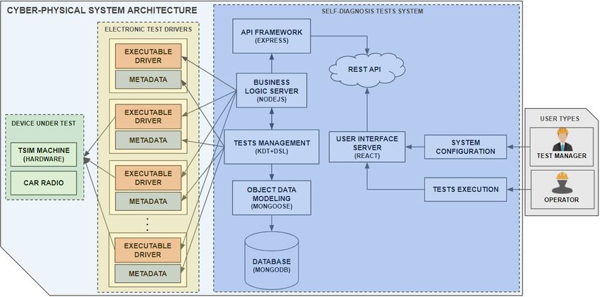
3.2 General Architecture for Cyber-Physical System
In this section, the final CPS architecture is presented and explained, where we integrate all
its components with the self-diagnosis tests system. This architecture enables the CPS to
diagnose itself and, thus, be able to identify the failures in case of any internal error. The
architecture, being the final abstraction of the system, can be seen in Figure 6.
Figure 6 Proposed architecture for a self-diagnosis test system integrated with the CPS.
In this architecture, we can easily identify 4 component groups in which three of them
will form an integral part of the CPS: Devices Under Test, Electronic Test Drivers and the
Self-Diagnosis Tests System. The last group will be an important intervenient, but it is not
an integral part of the CPS, the User Types. Each of these groups will be explained in detail,
as each has its particularities.
S L AT E 2 0 2 119:8 Self-Diagnosis Tests System Using a DSL for Creating New Test Suites
The Devices Under Test group contains, as the name implies, the devices that can be
subjected to tests which are the car radios and the machine itself. The elements CAR RADIO
and TSIM MACHINE represent the two types of devices, the car radio and the machine,
respectively. The Electronic Test Drivers group is responsible for the primitive tests of the
system, which in this case will be mostly electronic tests, but which can be any type of test
as long as they respect the same integration format. Each element of this group must respect
the following format:
EXECUTABLE DRIVER – Provides an executable driver file to run that will contain several
primitive tests that can be run and test the Devices Under Test;
METADATA – Provides a metadata file that contains all the information about the tests
that the driver can perform.
The Self-Diagnosis Tests System group is where the system developed in this work is
represented, which will allow users to manage and execute the system tests. This system will
be fed with primitive tests from the group of Electronic Test Drivers. The TESTS MANAGEMENT
element is responsible for loading all the metadata of the primitive tests, available in the
METADATA files of the Electronic Test Drivers group, and managing them so that they are
saved in the system database and are available for execution.
The link element with the system database is the OBJECT DATA MODELING that will make
the connection and handle queries and transactions to the database, which is the DATABASE
element.
This test management is done through the KDT methodology, and the configuration
of new test suites made through the developed DSL. The tests will be performed by the
BUSINESS LOGIC SERVER element, which will receive the execution orders from the end-user
and proceed with the executions. The way to do this is to execute the drivers that are
available as executable files. This Server will know which tests are available to execute on
each driver since the TESTS MANAGEMENT element has already collected the metadata of all
drivers and at that moment made available for execution, all the tests contained therein.
This entire organization is orchestrated by the Server, which is responsible for the logic of
the system and is represented by the element BUSINESS LOGIC SERVER. This Server not only
controls all the data and logic of the system but also defines the routes and types of requests
that can be made by the Client-side. It defines the services that will be available and this
is called an API. The API FRAMEWORK element is responsible for creating and providing a
REST API for any client to access, but obviously with the appropriate permissions, also
defined by the BUSINESS LOGIC SERVER.
In this system architecture, USER INTERFACE SERVER represents the Client-side, that is,
it is the server responsible for creating the web interface for end-users. It makes HTTP
requests specifying the services, through routes, that it wants to access, to obtain the data it
needs for its pages. Two types of interfaces are available, the execution interface, represented
by the TESTS EXECUTION element, and the test and configuration management interface,
represented by the SYSTEM CONFIGURATION element. Each of these interfaces will have its
correspondent as a user, which brings us to the last group specified in the architecture, the
User Types.
This group is represented by the USER TYPES element and represents the different types
of users of the final system. The first and most basic type of user is the OPERATOR, that is,
the industrial operator who is working and commanding the CPS and performs only the
tests or test packages of the system. The second type of user, already more sophisticated, is
the TEST MANAGER, who is someone with the responsibility of managing the entire system,
using the appropriate interface for that.R. B. Pereira, J. C. Ramalho, and M. A. Brito 19:9
4 Implementation
This section describes the implementation of the system and its validation. Thus, Section 4.1
explains each collection of data maintained in our database. Section 4.2 describes the
Backend tier where the system logic is, including the management of the system data and
the configuration and execution of the tests. Section 4.3 describes the Frontend tier that
contains the user interface and the different features available for each type of user. Finally,
Section 4.4 presents the results obtained from the validation performed to ensure the correct
functioning of the system.
4.1 Database
For the database, MongoDB was used, which is a document database, that is, it stores
the data in the form of JSON documents. According to the data that the system needs, 5
collections of data have been identified to be stored in the database: Configurations, Tests,
Packages, Reports and Schedules.
The configuration collection contains attributes about some configurations that may differ
from machine to machine and are necessary to ensure the correct functioning of the system.
The tests collection stores all metadata for the system’s primitive tests. This metadata
is provided by those who create and make the primitive tests available, so they are only
imported into the system database and updated whenever there are changes. The packages
collection stores all metadata for the new test suites that are created in the system from the
primitive tests. The reports collection stores all reports of execution of primitive tests or test
packages in the system. The schedules collection stores all primitive test executions or test
suite executions scheduled for a specific time by the user.
After specifying the data to be saved in each collection of the system’s database, the next
section will explain how the system interacts with the database, through queries, to obtain
the data for its operation.
4.2 Backend
The Backend is the system tier responsible for managing the database and making the data
available to Frontend. Therefore, framed in the MVC architecture, it is the Controller of the
system and establishes the connection between the database and the user interfaces, thus
guaranteeing the integrity of the data, not allowing other components to access or change
them.
The technology used to develop this server was Node.js combined with Framework Express.
This server is organized so that there is a division of the code according to its function, that
is, instead of all the code being in one file, it was divided into different files and directories
according to its purpose on the server. This will allow the reuse and modularity of the
developed code, which will also facilitate its maintenance and understanding in the future.
Thus, the server structure is as follows:
Models: Here are the models that correspond to the collections saved in the database.
Each model contains the attributes corresponding to its collection and performs validations
related to data types to ensure that wrong data types are not inserted into the database;
Controllers: Here are the files responsible for performing all system operations, such as
database queries, executing primitive tests and test suites, and creating new test suites
using the DSL defined;
S L AT E 2 0 2 119:10 Self-Diagnosis Tests System Using a DSL for Creating New Test Suites
Grammar: Corresponds to the DSL developed for the system, where is the grammar,
composed by a Lexer and a Parser, and the Visitor that generates the code for the new
test suites;
Routes: Here is the file that routes the requests, from the client, that is, from the user
interfaces to the controllers, according to the URL request. As soon as the requested
operations are completed, sends the requested data to the client.
Each of these elements mentioned above, has a fundamental role in the Server’s logic, so
each of them will be explained in the next subsections individually.
4.2.1 DSL
The DSL developed aims to enable the creation of new test suites, from the primitive tests
available in the system, with rules and logic applied. This will allow the test suites to
be optimized to execute in the shortest possible time and may shorten certain executions
whenever the suite specifies it. The language was created from the identification of terminal
symbols, that is, the symbols that would be identified by Lexer. After this step, the Parser
was created, where the rules of logic and sentence construction of the grammar are specified.
The terminal symbols of the DSL are shown in Table 1, where the respective descriptions
are also shown.
Table 1 DSL Symbols Description.
Symbol Description
keyword Catches the keywords in the script
Catches the “next” symbol, which means that after that symbol the next block
->
to be executed arrives
( Catches the opening parenthesis
) Catches the closing parenthesis
? Catches the conditional expressions from the script
: Catches the next block of code to be executed when a condition is false
& Catches the logical operator that means intersection
| Catches the logical operator that means union
; Catches the end of the script
The Lexer structure is shown below in Listing 1:
Listing 1 Grammar Lexer.
lexer grammar TestLexer ;
NEXT : ’->’ ;
AND : ’& ’ ;
OR : ’| ’ ;
IF : ’? ’ ;
ELSE : ’: ’ ;
RPAREN : ’) ’ ;
LPAREN : ’( ’ ;
END : ’; ’ ;R. B. Pereira, J. C. Ramalho, and M. A. Brito 19:11
KEYWORD : ([ A - Za - z ]+([/ _ -][ A - Za - z ]+)*)
;
WS
: [ \ r \ n \ t ] -> skip
;
The structure of the Lexer is quite simple, starting with its identification and then just
specifying all terminal symbols that must be recognized. The way these symbols are specified
is through regular expressions, that is, for each symbol the regular expression that represents
it is defined, however, always taking care that this definition does not include unexpected
elements and, therefore, is not ambiguous.
The symbols we see in this grammar are very intuitive and this is also one of its advantages,
as it will be easy for the end-user to understand, which is one of the objectives. The only
symbol that gives rise to any further explanation is the KEYWORD symbol. This symbol must
recognize all the names of the primitive tests introduced in the script and, therefore, its
regular expression includes isolated words or also the composition of several words, thus
giving the user some freedom to be more expressive in the choice of keywords since this it is
also the purpose of the KDT methodology applied in the system.
After defining the terminal symbols and the Lexer specification, it is time to specify the
sentence construction rules with these symbols and this is done in the Parser, which is shown
below in Listing 2:
Listing 2 Grammar Parser.
parser grammar TestParser ;
options {
tokenVocab = TestLexer ;
}
test
: statement END
;
statement
: condition # Conditional
| seq # Sequence
;
condition
: expr IF statement ELSE statement # IfElse
| expr IF statement # If
;
seq
: KEYWORD ( NEXT statement )*
;
expr
: LPAREN KEYWORD ( AND KEYWORD )* RPAREN # And
| LPAREN KEYWORD ( OR KEYWORD )* RPAREN # Or
;
S L AT E 2 0 2 119:12 Self-Diagnosis Tests System Using a DSL for Creating New Test Suites
The Parser also starts with its identification, following the reference for the Lexer that
it provides the symbols to be able to know which are the terminal symbols. After these
two steps, the sentences of the grammar are specified and here there is no more than a
specification of the sequences that the elements of the language can follow. We can see,
for example, in the element statement two possibilities. One possible statement is the
condition that represents a conditional expression and the other possibility is a seq that
represents a tests sequence. The most important part of the Parser to retain is the elements
that come at the end of the lines for each possibility determined at the beginning of words by
a #. This allows the Visitor to know the possible paths in the parsing tree that this Parser
will generate.
So that this grammar can now be used by the system and generate the parsing tree that
will be interpreted by the Visitor, it is still necessary to find a way to use it in the system.
Since ANTLR offers the transformation of these grammars for several known programming
languages, we will proceed to transform the grammar into JavaScript and include the code
directly in the system. For this, it is necessary to execute the following command:
$ antlr4 -Dlanguage=JavaScript Lexer.g4 Parser.g4 -no-listener -visitor
In this command, we specify the Lexer and Parser to be transformed and we also specify
that we do not want the generation of a Listener because, by default, it generates the Listener.
Finally, we specify the generation of a Visitor because, by default, it does not generate the
Visitor. After executing this command, several files will be generated, among which, the
Visitor that will be the most important in the next steps, as this is where the code to be
generated for the new test suites will be specified.
We can see below, in Listing 3, an example of a Visitor function:
Listing 3 Grammar Visitor.
TestParserVisitor . prototype . visitAnd = function ( ctx ) {
this . auxOp = 0;
for ( let i = 0; i < ctx . KEYWORD (). length ; i ++) {
this . auxList . push ( ctx . KEYWORD ( i ));
}
return "";
};
The Visitor’s strategy developed is to go through the code script through the elements
specified in the Parser and each element generate the corresponding code. The generated
code, within the Visitor, is nothing more than a string that is incremented and filled up to
the end of the parsing tree. All keywords are also being saved in a list so that the list and
the string containing the generated script are returned at the end. The list of keywords is
necessary because after generating this code it will be necessary to match the keywords with
the primitive tests but this is a process already done in the packages controller.
4.3 Frontend
The frontend is the system tier responsible for creating and managing graphical interfaces
for end-users. In this case, there are two types of users in the system, and it is important to
understand well the limits on what each one should be allowed to do or not do. The first
type of user, more basic, will only have access to the execution of primitive tests and test
suites. The second type of user, already responsible for managing the system and also the
test suites for it, has access to all other features. The technology used to develop this tierR. B. Pereira, J. C. Ramalho, and M. A. Brito 19:13
was React, as it will allow us to create dynamic interfaces, with components managing their
state and the possibility to compose the components themselves. This allows the code to be
modularized and, in the future, it will be easier to understand the code.
4.3.1 Components
As mentioned, the development of components in React becomes an asset, but to master the
use of technology it is necessary to understand the fundamentals and the way the components
interact with each other. The three concepts that we highlight are the following:
State: The state of a component is mutable and can be changed by the component itself,
due to the actions performed by the user. Information stored in a component’s state can
be accessed as attributes of the component, such as “this.state.name”;
Props: Props are state information from a parent component to a child component, so
the child cannot directly change the props but can access them in the same way as the
parent, such as “this.props.name”. They are generally used to determine some properties
of the child component when it is created;
Events: Events are how the child component should inform the parent component of
changes that have occurred. This is how a child component can change the state of
the parent component, through events that will inform the parent component so that it
updates its state.
Thus, to understand how these concepts apply in practice and make the most of the use
of React components, we can see below, in Figure 7, an illustration of how these concepts
are related:
Figure 7 Interactions between reaction components.
4.3.2 Obtaining API data
Another important aspect for this part of the system to work as planned is to obtain the data
that is managed by the Backend tier. For the graphical interfaces built to be as optimized as
possible and quick in obtaining data, so that the user does not have to wait long to load
the pages, the data must be obtained in the best way. And here the decision made was that
the parent components of each page make the data requests to the API at the time of its
creation. With this, what happens on the system pages is that whenever the user changes
the page or enters a new page, the data is requested and loaded. This will allow the actions
S L AT E 2 0 2 119:14 Self-Diagnosis Tests System Using a DSL for Creating New Test Suites
taken by the user on the components belonging to these pages to be carried out much more
quickly, giving the user the perception that nothing has happened when real events and state
changes have already occurred witch allows the page to become dynamic with desired speed.
The way to obtain the data is through HTTP requests, explained previously, therefore,
to make the code clearer, a dedicated file was created for request methods. This file contains
the base URL of the Data API and all methods add only the route and sub-route as needed.
We can see below, in Listing 4, an example of a method of obtaining data by making an
HTTP request to the data API:
Listing 4 Example of request to obtain API data.
export const getTests = async () = > {
try {
const response = await axios . get ( ‘ $ { url }/ tests ‘);
return response . data ;
} catch ( error ) {
const statusCode = error . response ?
error . response . status :
500;
throw new Error ( statusCode . toString ());
}
};
In this example, we can see how HTTP requests are made to the API. These requests
are made through the imported module “Axios” since the technology does not provide this
functionality natively. Another important feature that we see in this example is the use of
the keyword “await”, which in this particular case makes the method wait for the results
of the API. This is also one of the strong characteristics of the technologies used, as they
perform I/O operations asynchronously by default.
4.3.3 User Interfaces
Only one page will be demonstrated in this paper for the same reason that previously only
the implementation of DSL was demonstrated. This is the page for managing and configuring
new test suites for the system, which can be seen in Figure 8. The user has on this page at
his disposal the list of existing packages in the system, where he can remove or edit them.
There is also a form for creating a new test suite, where the user only needs to specify the
name, description and code of the new test suite. The code is written with the DSL presented
earlier. In this case, the elements that can be used to write the code are the connectors
below the form that are made available to the user according to the status of their script, to
help the user and try to avoid errors. The other elements to include in the script are the
primitive tests, and these are made available in a list next to the form where the user can
even see their description to understand what the test does. To include a test in the script,
the user just needs to click on it and it is automatically added to the script. This way, the
user does not need to write anything manually, having to select the elements he wants to
add to the script.
4.4 Validation
Having already implemented the system with all the requirements that were established,
several test cases were created to be carried out in the system to validate the solution and
confirm the fulfilment of all the proposed objectives. The first tests were carried out on theR. B. Pereira, J. C. Ramalho, and M. A. Brito 19:15
Figure 8 Package creation and management page.
most fundamental functionalities of the system, the execution of the tests and the automation
of the update in the face of changes introduced in its supply. Several test scenarios were
simulated and the system behaved as expected, passing all performed tests.
In total, 28 test cases were carried out covering all the functionality of the system and in
some of them with more than one test case. No more test cases were carried out because the
time it would take to do so is immense, but the test cases performed were considered to be
the most comprehensive cases and therefore will give the greatest coverage of requirements.
After analyzing all the results obtained in the tests and verifying that they all passed, we
can say that all requirements have been successfully implemented and the system is ready to
be integrated with the other components.
5 Conclusions and Future Work
The main contributions of this paper are the design of the architecture to integrate a self-
diagnosis tests system into a CPS and its implementation. This architecture provides a
modular and extensible solution so that the system can be integrated with the CPS and
perform any type of test. The system was implemented based on the proposed architecture,
but only the part of the implementation corresponding to the DSL was demonstrated due to
the paper size limit. To validate the implementation of the system and its compliance with
the established requirements, 28 test cases were carried out to cover all requirements. All
test cases have passed and, therefore, the system meets all the objectives.
The proposed modular and extensible architecture represents an innovation for research
in self-diagnosis systems and CPS, as it allows the combination of these two types of systems,
through the use of KDT methodology with a DSL to manage and configure the tests of the
system. This architecture also allows the execution of the tests to be done remotely or by any
other system with permission to make HTTP requests to the API REST provided. Although
the focus of the architecture is the application in a CPS, it is also applicable to any type of
system, since it is generic to accept any type of test. With this work, we proved that it is
possible to integrate self-diagnosis tests systems into a CPS with a practical and also generic
solution that can be integrated with other types of testing systems.
As future work, it would be interesting to improve the interface for creating new test
suites in the system. Although the solution currently implemented is practical and allows
good use, it could be even more practical and simple for the user if a drag and drop window
were developed in the design of new test suites instead of writing a code script.
S L AT E 2 0 2 119:16 Self-Diagnosis Tests System Using a DSL for Creating New Test Suites
References
1 Márcio Filipe Alves Carvalho. Automatização de testes de software, 2010. URL: https:
//files.isec.pt/DOCUMENTOS/SERVICOS/BIBLIO/teses/Tese_Mest_Marcio-Carvalho.pdf.
2 S. Ciraci, J. C. Fuller, J. Daily, A. Makhmalbaf, and D. Callahan. A runtime verification
framework for control system simulation. In 2014 IEEE 38th Annual Computer Software and
Applications Conference, pages 75–84, 2014. doi:10.1109/COMPSAC.2014.14.
3 Guru99. What is automation testing?, 2021. URL: https://www.guru99.com/automation-
testing.html.
4 R. Hametner, D. Winkler, and A. Zoitl. Agile testing concepts based on keyword-driven
testing for industrial automation systems. In IECON 2012 - 38th Annual Conference on IEEE
Industrial Electronics Society, pages 3727–3732, 2012. doi:10.1109/IECON.2012.6389298.
5 Felienne Hermans, Martin Pinzger, and Arie Van Deursen. Domain-specific languages in
practice: A user study on the success factors. In Lecture Notes in Computer Science (including
subseries Lecture Notes in Artificial Intelligence and Lecture Notes in Bioinformatics), 2009.
doi:10.1007/978-3-642-04425-0_33.
6 Jingfan Tang, Xiaohua Cao, and A. Ma. Towards adaptive framework of keyword driven
automation testing. In 2008 IEEE International Conference on Automation and Logistics,
pages 1631–1636, 2008. doi:10.1109/ICAL.2008.4636415.
7 Tomaž Kosar, Sudev Bohra, and Marjan Mernik. Domain-Specific Languages: A Systematic
Mapping Study. Information and Software Technology, 2016. doi:10.1016/j.infsof.2015.
11.001.
8 Charles W. Krueger. Software Reuse. ACM Computing Surveys (CSUR), 1992. doi:10.1145/
130844.130856.
9 Edward A. Lee. Cyber physical systems: Design challenges. In Proceedings – 11th IEEE
Symposium on Object/Component/Service-Oriented Real-Time Distributed Computing, ISORC
2008, 2008. doi:10.1109/ISORC.2008.25.
10 Marjan Mernik, Jan Heering, and Anthony M. Sloane. When and how to develop domain-
specific languages. ACM Computing Surveys, 2005. doi:10.1145/1118890.1118892.
11 Jens Palsberg and C. Barry Jay. The essence of the Visitor pattern. In Proceedings –
International Computer Software and Applications Conference, 1998. doi:10.1109/CMPSAC.
1998.716629.
12 T. J. Parr and R. W. Quong. ANTLR: A predicated-LL(k) parser generator. Software:
Practice and Experience, 1995. doi:10.1002/spe.4380250705.
13 Terence Parr and Kathleen Fisher. LL(*): The foundation of the ANTLR parser generator.
In Proceedings of the ACM SIGPLAN Conference on Programming Language Design and
Implementation (PLDI), 2011. doi:10.1145/1993498.1993548.
14 Terence Parr, Sam Harwell, and Kathleen Fisher. Adaptive LL(*) parsing. ACM SIGPLAN
Notices, 2014. doi:10.1145/2714064.2660202.
15 Gabriele Tomassetti. The antlr mega tutorial, 2021. URL: https://tomassetti.me/
antlr-mega-tutorial/.
16 X. Zhou, X. Gou, T. Huang, and S. Yang. Review on testing of cyber physical systems: Methods
and testbeds. IEEE Access, 6:52179–52194, 2018. doi:10.1109/ACCESS.2018.2869834.You can also read