AUGMENTED REALITY-BASED INTERACTION MECHANISM FOR THE CONTROL OF INDUSTRIAL ROBOTS - DIVA
←
→
Page content transcription
If your browser does not render page correctly, please read the page content below

DEGREE PROJECT IN MECHANICAL ENGINEERING,
SECOND CYCLE, 30 CREDITS
STOCKHOLM, SWEDEN 2020

AUGMENTED REALITY-BASED
INTERACTION MECHANISM FOR
THE CONTROL OF
INDUSTRIAL ROBOTS

YONGQING ZHAO

KTH ROYAL INSTITUTE OF TECHNOLOGY
SCHOOL OF INDUSTRIAL ENGINEERING AND MANAGEMENT
SAMMANFATTNING
För närvarande används AR/VR-enheter och tekniker kontinuerligt för att kontrollera de olika
typerna av robotar inom branschens aspekter. Många utvecklare har genomfört pick-and-
place-experimentet på den verkliga roboten genom att interagera med den virtuella roboten i
AR/VR-enheterna. Men användargränssnittet i AR/VR-enheterna är bristen på hela
kontrolllogikmekanismen för att hjälpa användare att använda styrsystemet enkelt.

Med spridningen av utvecklande AR/VR-teknologier introduceras i branschen. Det är
uppenbart att användargränssnittet måste ha en komplett interaktionsmekanism för att ge nya
upplevelser för användare. Baserat på översynen av litteratur om avsikten att hjälpa
användare att interagera med en robot med hjälp av AR/VR-enheter, koncentrerade denna
masteruppsats på utformningen av front-end i HoloLens och dess datakommunikation med
den virtuella roboten i PC. Baksidan vid testning i denna avhandling är baserad på de verk
som Mingtian Lei har dong i sin avhandling, kallad Grafiskt gränssnitt och
robotkontrollsystemdesign med kompensationsmekanism.

Denna avhandling gav de grova prototyperna om användargränssnittet med en
kontrolllogikmekanism i HoloLens för att manipulera den verkliga roboten, KUKA KR6 R700
Sixx. Testresultaten i denna avhandling baseras fritt på experimentet med Pick and Place.
Resultatet visar att användaren kan styra den verkliga roboten för att välja målobjektet fritt och
placera det i slutpositionen utan kollision med andra objekt. Noggrannheten och kontinuiteten
i driften i pick-and-place-testet behövs för att ytterligare förbättras för att hjälpa användare att
spara tid när de använder HoloLens för att kontrollera industrirobotar.

                                                 2
ABSTRACT
Currently, AR/VR devices and technologies are continuously applied to control the different
types of robots in the aspects of the industry. A lot of developers have accomplished the pick
and place experiment on the real robot through interacting with the virtual robot in the AR/VR
devices. However, the User interface in the AR/VR devices is the lack of the whole control
logic mechanism to help users operating the control system easily. With the spread of
developing AR/VR technologies are introduced into the industry. It is obvious that the user
interface needs to have a complete interaction mechanism in order to give new experiences
to users.

Based on the review of literature about the intention to help users to interact with a robot using
AR/VR devices, this Master thesis concentrated on the designing of front-end in the HoloLens
and its data communication with the virtual robot in PC. The back-end during testing in this
thesis is based on the works that Mingtian Lei has dong in his thesis, called Graphic Interface
and Robot Control System Design With Compensation Mechanism.

This thesis gave the rough prototypes about the user interface with a control logic mechanism
in the HoloLens to manipulate the real robot, KUKA KR6 R700 Sixx. The test results in this
thesis is based on the experiment of Pick and Place freely. The result shows that the user is
able to control the real robot to pick the target object freely and place it in the final position
without collision to other objects. The accuracy and the continuity of operation in the pick and
place test are needed to have further improved to help users to save time when using
HoloLens to control industrial robots.

                                                3
TABLE OF CONTENTS
SAMMANFATTNING                                                      2
ABSTRACT                                                            3
TABLE OF FIGURES                                                    5
INTRODUCTION                                                        6
    Overview                                                        6
    Research Background                                             7
    Research Scope                                                  7
    Roadmap                                                         8
    Research Delimitation                                           8
    Outline of the thesis                                           9
LITERATURE REVIEW                                                   10
    Terminology Definition                                          10
    Previous Studies and Related Works                              11
SYSTEM ARCHITECTURE                                                 14
    HoloLens                                                        14
    Unity                                                           15
    Backend                                                         15
METHODOLOGY                                                         16
    Function Design                                                 16
    Logic Flow                                                      18
    Data communication mechanism between HoloLens and robot in PC   19
IMPLEMENTATION                                                      21
    Hardware                                                        21
    Software tools and Packages                                     21
    Experiment and Results                                          22
CONCLUSION                                                          26
REFERENCE                                                           28

                                      4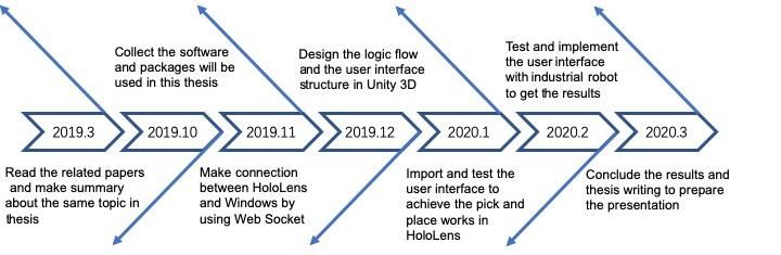
TABLE OF FIGURES
Figure 1 Microsoft HoloLens                    6
Figure 2 KUKA KR6 R700 Sixx                    6
Figure 3 Timeline of this thesis               8
Figure 4 System Structure                     14
Figure 5 Interaction Design                   16
Figure 6 Logic Flow1                          18
Figure 7 Data Communication                   19
Figure 8 File Communication                   21
Figure 9 Before edit robot                    22
Figure 10 After edit robot                    22
Figure 11 Before edit the cube                22
Figure 12 After edit the cube                 23
Figure 13 After add the via point             23
Figure 14 Reach to the first vi point         23
Figure 15 Reach to the second via point       23
Figure 16 Before rotate the gripper           24
Figure 17 After rotate the gripper            24
Figure 18 After press the Pick button         24
Figure 19 Confirm the second final position   24
Figure 20 trajectory visualization            25
Figure 21 Place the object                    25

                                          5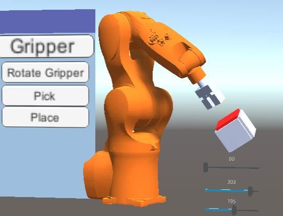
1. INTRODUCTION

1.1 Overview

This report presented the result of a Master of Science thesis project at Royal Institute of
Technology(KTH). The objective of this master thesis is to develop the interaction mechanism
in Augmented reality for industrial robots. The Microsoft HoloLens glass, as it shows in figure
1, is decided as the AR device to help the human operator to interact with an industrial robot.
The Unity platform was applied to transmit data with HoloLens. The type of industrial robot in
this thesis is KUKA KR6 R700 Sixx in figure 2.

        Fig 1 Microsoft HoloLens [1]                     Fig 2 KUKA KR6 R700 Sixx [2]

1.2 Research Background
Nowadays, AR/VR technology is commonly used to be associated with gaming and
entertainment. However, there is a large sum of potential value that has been developing in a
wide array of industries. Specifically, in industrial robots, AR/VR devices are becoming more
popular as it certainly speeds up the robot learning process by AI and improves the way human
operators and robots work together by interaction with the virtual robot. Traditionally, robots
will be left alone to do their job automatically after being programmed. But in recent years,
robots evolved beyond the phase of mindless laborers that perform simple and repetitive tasks,
it became necessary for people to interact with robots during various work tasks [3]. However,
the application of AR/VR technology will give the assistance for the user to see the field of
vision of the robot in the window, and the user is able to predict and customize its planning
trajectory according to its movements, existing obstacles, and other factors.

                                              6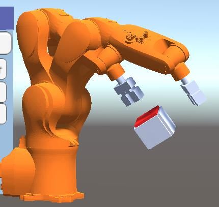
1.3 Research Scope
1.3.1 Research Motivation

In the previous studies on the interaction between AR/VR devices and industrial robots, a lot
of researchers have developed a user interface which enables human operators to control the
virtual robot in the AR/VR devices to accomplish the pick and place experiment. Most of them
use the virtual sphere or cube existing in the AR device to represent the real target object,
then the human operator can put the virtual object overlap on the real object, the robot will
receive the data from the device to move to the target position.

However, the control method or the trajectory planning has two disadvantages, the one is that
the user is not able to customize the robot gesture which picks and places the target object.
Because the robot gesture in which it picks the object has been pre-fixed either the horizontal
direction or vertical direction. Another is that the direction of via points when the robot reaches
could not be designed as the user wants. It is acceptable when controlling the robot to achieve
an uncomplex job. But when it comes to a difficult job, for example, the target object is put in
the hole or inside of another object. It is not possible to use the method currently to complete
this work. So, the method currently is considered a lack of flexibility and customization and as
such there exists a need for the development of simple alternative methods. At present, there
is no suitable method that has developed to enable the user to interact with a robot as they
desire.

1.3.2 Research Objective

The objective of this thesis is to develop an interaction mechanism that could be applied in the
Microsoft HoloLens to control the robot, KUKA KR6 R700 Sixx, to achieve the experiment of
Pick and Place. There are several goals to be planned in this project before beginning.

   ●   The via point can be created to avoid physical collision with obstacles in the real world
       when working on the Pick and Place experiment.

   ●   The orientation of the end-effector should be customized to pick or place the target
       object as the human operator desires.

   ●   The trajectory planning of the robot should be reviewed before the industrial robot
       moves.

                                                7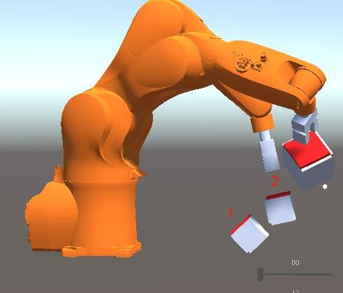
1.4 Roadmap

                                 Fig. 3 Timeline of this thesis

Figure 3 shows the timeline of this thesis from the beginning. At the beginning of this thesis, a
lot of conferences and published papers which have corresponded with my thesis topic have
been detailed, read and noted. This stage gave an understanding of what kinds of solutions
have been developed and how deep those researches have been currently.

Then different packages and software were collected to be further applied in the thesis, such
as the Vuforia recognition was decided to use in this thesis to recognize and locate the virtual
robot in the user interface in HoloLens. The developing platform is Unity and the programming
language used is C#. Because Unity is the only platform that was supported by HoloLens at
present. In the next stage, data communication has been completed between Unity in PC and
HoloLens using WebSocket. It means that the virtual robot in HoloLens can receive the robot
data from the PC. Meanwhile, the robot in Unity on the PC also can get the related data to
HoloLens.

The next stage was to design and develop the interaction mechanism which enables the
human operator to control the virtual robot friendly and complete the pick and place experiment
in the HoloLens. Then the next step was to make a connection between HoloLens and the
real robot to implement the experiment, such as to send and receive the 6-axis data, gripper
control, and robot speed control. The final stage was to collect the data and record the
information needed and start writing this thesis to prepare the presentation.

1.5 Research Delimitation
The project presented in this report is a 30 credits Master of Science thesis, which covered 24
weeks of work in KTH. Since the acquisition of information and knowledge is influenced by
time and device, the delimitations of this project are listed below:

   ●   The industrial robot in the experiment is KUKA KR6 R700 Sixx. The Microsoft
       HoloLens is chosen as an AR device to control the robot.

                                               8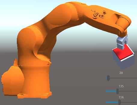
●   The Unity 3D is the Intermediatator of AR devices to send and receive the data to/from
       the ROS.
   ●   The Pick and Place experiment is only run once instead of continuously pick or place
       the other objects.

1.6 Outline of the thesis

This section clarity the structure of this thesis report which includes each main chapter in this
article and the main contents of each chapter listed.

Chapter 1: Introduction – This chapter presents the description of the theme of the research,
including the overview, background of research, the motivation of the research, the scope of
this research and the roadmap of this thesis.

Chapter 2: Literature Review – This chapter lists the theoretical definitions involved in the
project or mentioned in the later articles and reviews the results of previous research in the
same field.

Chapter 3: System Architecture – In this chapter, it presented the system structure and
explanation of the works in this thesis.

Chapter 4: Methodology – This chapter described the research approach used to carry out the
thesis. It also provides the general steps from the preparation to the contents structure of this
project.

Chapter 5: Implementation – Verify the system architecture by actual cases.

Chapter 6: Conclusion – Conclude the project and present some discussion and evaluation of
the report. It also mentions the future recommendations about this project

                                                9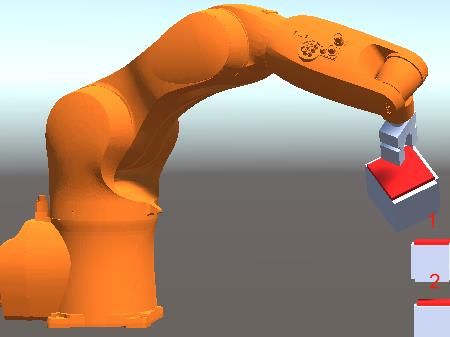
2 LITERATURE REVIEW
This chapter includes two sections, the first section describes the terminology definitions
involved in this thesis or mentioned in the later article. The second section documents and
reviews the results of previous research related to the topic in the same field.

2.1 Terminology Definition
2.1.1 Augmented Reality

Augmented reality (AR) is an interactive experience of a real-world environment where the
objects that reside in the real world are enhanced by computer-generated perceptual
information, sometimes across multiple sensory modalities, including visual, auditory, haptic,
somatosensory and olfactory [4]. AR can be defined as a system that fulfills three basic
features: a combination of real and virtual worlds, real-time interaction, and accurate 3D
registration of virtual and real objects [5].

AR interfaces have three main features: (1) users can view both real and virtual objects in a
combined scene, (2) users receive the impression that virtual objects are actually expressed
and embedded directly in the real world, and (3) the virtual objects can be interacted with in
real-time [6].

With the application of AR in industry, it will increase the efficiency and time-saving for the
human operator to manipulate the real robot to work on the repetitive tasks in practice.

2.1.2 Microsoft HoloLens

Microsoft HoloLens is a pair of mixed reality smart glasses developed and manufactured by
Microsoft. HoloLens was the first head-mounted display running the Windows Mixed Reality
platform under the Windows 10 computer operating system. The tracking technology used in
HoloLens can trace its lineage to Kinect, an add-on for Microsoft's Xbox gaming console that
was introduced in 2010 [7].

Windows 10 is used as the operating system for Microsoft HoloLens. The Universal Windows
Platform (UWP) serves as a uniform development platform for Windows 10 applications. For
the development of HoloLens applications, Visual Studio is used in combination with the game
development software Unity3D, for which Microsoft already provides basic functions such as
gesture and speech recognition [8].

                                              10
2.1.3 Unity 3D
Unity3D is a powerful cross-platform 3D engine and a user-friendly development environment.
Easy enough for the beginner and powerful enough for the expert; Unity should interest
anybody who wants to easily create 3D games and applications for mobile, desktop, the web,
and consoles [9].
Unity 3D is the only platform that was officially supported by Microsoft HoloLens. It contains a
variety of tools, packages, and resources that allow the developer to easily make VR and AR
applications and publish them on the devices.
2.1.4 Vuforia Engine
Vuforia Engine is the most widely used platform for AR development, with support for leading
phones, tablets, and eyewear. Developers can easily add advanced computer vision
functionality to Android, iOS, and UWP apps, to create AR experiences that realistically
interact with objects and the environment [10].
Vuforia brings the power to connect HoloLens, it will have the ability to detect images and
objects in the real world. The developers can apply this capability to overlay step-by-step
requirements on top of machinery in industry or add virtual digital features to a physical
product. Vuforia Engine also offers a broad range of features and targets with great flexibility
when developing AR applications.
2.2 Previous Studies and Related Works
2.2.1 Interaction system between AR with an industrial robot
Many researchers have been conducted in the field concerned to be of interest to this project.
As for the interaction mechanism about human-robot collaboration through augmented reality.
In the study of [11] in 1993, it presented an overview of ARGOS (Augmented Reality Through
Graphic Overlays on Sterro video) to prove that possibility by integrating virtual measures with
industrial robots. In 2004, in this article [12], Rainer Bischoff developed several AR interaction
prototypes that illustrate the suitability of AR-based HRI, especially for relatively complex
industrial robots. This study [13] further demonstrated that the AR-HRC ( Human-Robot
Collaboration)interface resulted in better accuracy and fewer close calls as opposed to the
other two interfaces, direct teleoperation and an Exo-centric view of the robot in the real world.
Bagchi, Shelly and Jeremy A. Marvel [14] presented a robot user interface which provides not
only effective robot control, but also task training, feedback, and better situational awareness
for bringing human operators more effective, particularly for human-robot collaboration.
11In this paper [15], it proposed the experiment results of a control system with an industrial
robot based on user’s interactions with a virtual model in HoloLens. The robot can be
controlled in two modes. The first way is to through point to point instructions stored into ROS
topics and updated by the user with the HoloLens. The second way is to directly manipulate a
target which the robot will track. The results in this paper demonstrated that the
synchronization of the digital model on top of the real robot is more recommended. Because
it will achieve a more immersive interaction with the system for the human operator. This paper
[16] developed an alternative system which applied multimodal language in HoloLens for
interaction between industrial robots and humans. With the assistance of this method, the
robot understands the user’s intentions in a faster and more robust way. In the study [17], a
typical architecture consisting of 3 main parts is described: inter-face, controller, robots for
interactive programming of different robot types based on mixed reality. In this research [18],
it proposed and presented an AR-based interface for intuitive HRI. There are two methods
that have been generated. It has been developed, call the Euclidean distance-based method,
to assist the human operators who enable delete, select or insert spatial points. The monitor-
based visualization mode adopted allows human operators to perceive the virtual interface
augmented onto the real world. This paper [19] suggested that the virtual robot or outline of
the robot visualization style which over the real robot is more accepted by human operators.
This article [20] presented the ARRPS (Augmented Reality-assisted Robot Programming
System) system that provides the users with intuitive ways to customize and visualize the
robot movement and enhances robot path and task programming. This article [21] presented
a user interface that can control the real robot via clicking the button in HoloLens. In this way,
there are no requirements for a human operator without advanced professional skills of robot
control PAD. In this study [22], it developed an overview of the current referencing methods
used in AR-based human-robot interaction and object detection methods that are currently in
use in the industrial robots.
2.2.2 Trajectory planning for the virtual robot in Augmented Reality
A lot of researchers have presented and evaluated the method to create the movement path
for industrial robots to avoid collision with obstacles. In this paper [23], it presented a concept
for intuitive pick and place tasks using a service-oriented architecture between HoloLens and
UR5 industrial robots. Based on this structure, it becomes easy integration, exchangeability of
components, and scalability to multiple workstations and devices. The character of this method
can help the human operator to drag recognized objects and drop them at a desired position
to complete a pick and place task. This study [ 24] has developed a method to mitigate
industrial workers’ daily tasks regarding the visualization of the next possible assembly step
synchronized with a cobot in executing specific assembly works. The human operator can
check the process in which the final product can be simulated by visualizing virtual assembly
sequence elements in HoloLens even before the actual production begins. In this article [25],
it proposed a broker architecture that can integrate and control various robots from different
manufacturers and types. With the application of this broker architecture, a human operator
could manipulate the real robot to avoid collision with the obstacle to have a safe and fast
12manner. This report [26] presented an intuitive robot system that applies a hand-held pointing
device to represent via points for the robot end-effector and to trigger related actions to avoid
collision with real obstacles in augmented reality. This paper [27] has optimized the robot paths
for the planning trajectory. It allows the user to adjust the selected path in the HoloLens, and
add new paths by inserting points in the mixed reality environment. The human operator can
correct the paths as desired, connect them using a certain type of motion and command them
to the robot controller. The method demonstrated in this article enables the users, with limited
programming experience, to fully use the robotics fields through HoloLens and decrease the
complexity for human operators. This study in this article [28] proposed an AR robotic system
for trajectory interaction using HoloLens. Two experiments have been conducted, free space
trajectory, and contact surface trajectory. This system enables a human operator to plan and
customize the trajectory as they desire. This report [29] presented an approach, namely, Robot
Programming using Augmented Reality (RPAR), for robot trajectory planning, robot end-
effector orientation defining, and path optimization.
133 SYSTEM ARCHITECTURE
Fig 4 System Structure
The whole system architecture in this thesis is described in figure 4. As it shows, it includes
the four parts, HoloLens User Interface, Windows Environment, Backend, and Robot
Controller. In my works, most of my time was concentrated on the HoloLens User Interface
and Windows Environment. The part of Backend and Robot Controller are based on the
system developed in this paper [30].
3.1 HoloLens
In the HoloLens user interface, the human operator can use voices or hand gestures to control
the virtual robot to interact with industrial robots in the real world. There are three function
modules, robot recognition module, object-oriented planning module, and trajectory planning
and orientation module. The robot recognition module, as the first module when this system
is launched, will drive and show the virtual robot 1 in the view of the human operator when the
camera in HoloLens detects the image target. The object-oriented planning module is
developed to be triggered by the virtual robot 2. The virtual robot 2 will move to the destination
to work on the pick or place target object. The virtual robot 3 is only activated when the human
operator adds the via points to create the trajectory planning for the real robot. The virtual
robot 4 is the slave model of the real industrial robot. It will always follow the movements once
the real robot starts to move.
There is no data communication between virtual robot 1 and windows environment. The virtual
robot 2 has the capability to confirm the final gesture and send every joint angle to the virtual
robot 3. The virtual robot 2 will manage to transmit the gripper, speed parameter, and final 6-
joints angle to the windows environment. The virtual robot 3 is responsible to send its 6 joints
14angle of reach to via point to the windows environment if there are via points existed in the
robot trajectory. As the slave of a real industrial robot, the virtual robot 4 will receive the 6 axis
variables from the windows environment.
3.2 Unity
The virtual environment in Unity 3D includes the robot joint control and gripper & speed control.
The robot joint control will conduct the data communication that refers to 6 joints angle in the
txt file when it comes to send back to the HoloLens. The gripper control, as the name shows,
is to manage the open and close of the gripper. The speed control can control the robot
movement speed not only before moving but also the robot is moving. Those two parameters
will be also written in the txt file but send it to the servo controller to control the industrial robots.
3.3 Backend in ROS
The back-end of the experiment in this thesis is based on the Mingtian Lei’thesis, Graphic
Interface and Robot Control System Design with Compensation Mechanism. Because he has
developed the data communication between Unity and Kuka industrial robot. In his work, the
ROS in LINUX can record the robot 6-axis data which was extracted from KUKA Robot
Controller, then the recorded 6-axis data will be transmitted to the Unity using ROS-bridge
package, the virtual robot pos will be adjusted to have the same pos as the current real robot.
The virtual robot is also able to send its current pos to drive the real robot. Robot C-space
control and gripper & speed control will be executed in another way, those data will be written
to the Txt file in the Windows, the Eclipse will read the received data in the Txt file and send it
to the Robot Controller which will drive the real robot to move.
154 METHODOLOGY
4.1 Function design
Fig. 5 Interaction Design
As the figure 5 shows, there are three functional modular that are designed in the user
interface, robot, final position, via point and gripper. Those four buttons are the master layer
in the menu which the human operator will interact firstly. Each button consists of several child
buttons to control the corresponding works once it is clicked.
4.1.1 Robot
For the Robot modular in figure 5, there are different buttons to trigger the events related to
robots. The button of Display Robot means that the other three virtual robots will be
automatically shown right over the virtual robot 1. The Edit Robot button enables the human
operator to make changes to the position and rotation of the other three virtual robots. The
user can tap in air and drag the virtual robot to move to the target position. The rotation will
happen by sliding the three sliders which represent the x axis, y axis, z axis. The Speed Control
button means to control the movement speed of industrial robots. The position and rotation of
the virtual robots will be fixed once the user clicks the Confirm button while the virtual cube
will be shown on the around the end effector of the industrial robot.
4.1.2 Final Position
When the virtual cube is shown in the holographic environment, the child buttons under the
Final Position will be activated at the same time. This modular focus on to decide the final
position before pick or place starts. There are two child buttons available in this modular, Edit
Cube, and Confirm. The Edit Cube button is used to adjust the position and rotation of the
virtual cube. the virtual robot will be always following the position of the virtual cube once the
16virtual cube moves. This button will be essential when the user desires to pick or place the
target object in very tricky places. The Confirm button is used to fix the position and rotation
of the virtual cube.
4.1.3 Via Point
Once the user confirms the position and rotation of the virtual cube in a virtual environment, it
will come to the Via Point modular. In this modular, it concentrates on the part of via points
when the industrial robot is possible to have collision with the obstacles in real world. It will
also provide the trajectory visualization for the virtual robot. There are four child buttons in this
modular. The Add via point button can help the human operator to create many smaller virtual
cubes as the via points as they want. The Edit via points button will be responsible to adjust
the position or the rotation of smaller virtual cubes. The Delete via point button is applied to
delete those via points unneeded. The Confirm button is used to confirm all the position and
rotation of each via point. After this button is clicked, the virtual robot 2 will move to the target
via points one by one to present the visualization path. Once the position of all of the via points
are confirmed, the button of Send Data To Robot will be triggered to transmit the data to the
real industrial robot.
4.1.4 Gripper
This modular is responsible for controlling the gripper of the robot. It will be activated when it
comes to start picking or placing the target object. The Rotate Gripper button is used to control
the slide to rotate the orientation of the gripper. The button, called Pick, is applied to pick the
object. The robot will go down and close the gripper and go up by clicking up this button. The
Place button is used to control the robot to go down and open the gripper and go up.
174.2 Logic Flow
The figure 6 shows the logic flow behind the user interface in this thesis.
Fig. 6 Logic Flow
18When the system is launched, the HoloLens can recognize the virtual robot to decide the rough
position around the real industrial robot by detecting the image target. Then the virtual robot
will be put right over the real robot by hand gestures or button clicking. If the position of virtual
robot is not confirmed, then it will go back to the operation to change the position of virtual
robot. Once the position of virtual robot is confirmed, it will continue to the part of final position.
The position or rotation of the cube can decide the final position which the robot will pick. It
will go back to edit the cube again if the position is not confirmed. If the final position is
confirmed, the human operators can create the via point to customize the trajectory planning
of the industrial robot. The via point can be edited to decide the position and direction of each
via point. It will go to the trajectory visualization directly if there is no necessary to create the
via point. If the trajectory path is confirmed after the trajectory visualization is reviewed. Then
the gripper will be activated to start picking the target object. It will go back to the part of the
final position if the trajectory path is not confirmed.
4.3 Data communication mechanism between
HoloLens and robot in PC
Fig. 7 Data communication
The figure 7 shows the data communication among HoloLens, Unity, and industrial robot.
In this thesis, it only concentrated on the connections between HoloLens and Unity. As for the
user interface in the HoloLens, there are three virtual robots which are related to each other.
The virtual robot 1 will update its Cartesian coordinate parameters to virtual robot 2 once the
rough position is detected via Vuforia Engine. If there are via points existed in the trajectory
planning, then the virtual robot 2 will send the final 6-Axis variables to the virtual robot 3. The
virtual robot 3 will move to the position of virtual robot 2 after all the via points are got over.
As it shows in the figure 7, the Web Socket is applied in this thesis to make connection
between HoloLens and Unity. The virtual robot 2 is responsible to control the robot gripper
and movement speed. Moreover, it also sends and receive the 6-Axis data between Unity and
HoloLens. As it mentioned before, the virtual robot 3 will be only activated when there are via
19points in the trajectory planning. So, the virtual robot 3 will send its 6-Axis variables to the
robot in Unity when it reaches the each via point. The 6-Axis variables of the real robot will be
sent to Unity. The data will be written into the TXT file, then the virtual robot 4 will read the
data from the TXT file. The virtual robot 4 will be driven to move once the real robot starts to
move.
205 IMPLEMENTATION
5.1 Hardware
There are three hardware which are applied in this thesis. The Microsoft HoloLens first
generation is applied to help the human operator to interact with industrial robot in the virtual
environment. It can allow the user to using their voice commands or the hand gestures to
control virtual objects in immersive experience. The computer with Windows 10 operating
system is also applied to conduct the data communication with HoloLens. It is viewed as a
broker to connect HoloLens and industrial robot. The research robot type is KUKA KR6 R700
Sixx which is a compact 6-axis robot from KR AGILUS series. It integrates the energy supply
system and controller which name is KR C4 servo controller.
5.2 Software tools & Packages
For the robot recognition module, the Vuforia Engine was chosen in this thesis to show the
virtual robot in the user interface. The user has different options to decide to detect the
holographic object by 3D object target, image target and so on. In the method of controlling
virtual robot, there are many inverse kinematics available to control the virtual robot. The
Final IK (inverse kinematics) was applied to interact with a virtual robot arm by dragging
the end of it. The user can create a series of chain for the robot arm and drag the end
chain to move the whole virtual robot arm via CCDIK (Cyclic Coordinate Descent Inverse
Kinematics) which is one of the solver in Final IK.
It is unfortunate that there is no 3d model with FBX format file of KUKA KR6 R700 Sixx in the
KUKA official website to allow user to download directly. However, the kuka_experiemnet
package [31] is available for the developers to download which only be applied in the Linux
environment. Therefore, the rosbridge_suite [32] is applied to transform the Kuka 3D model
into FBX format file through the WebSocket between Unity and Linux. Even so, the 3d model
is not able to be used directly since its coordinate system of every joint has the conflicts with
the Final IK. So the 3d Kuka model was imported into the 3DMAX to adjust the coordinate
system of every joint to enable collaboration with Final IK in Unity 3D. The work flow among
Linux, Unity3D and 3DMAX is shown as figure 8.
Fig. 8 File communication
211.Transform the default format file into FBX format file.
2.Import the FBX format file into 3DMAX to change the coordinate system.
3.Export the 3d model in 3DMAX and import it into Unity 3D
The procedures in the figure 8 are important for those developers who want to use the Kuka
official 3d model. Since the developers do not need to recreate the 3d model in CAD software.
5.3 Experiment and Results
Fig. 9 Before edit robot Fig. 10 After edit robot
After the button of Display Robot and Edit Robot is clicked, the arrows and slider will be shown
in the user interface as it shows in the figure 9. There are two ways for the human operator to
change the position of virtual robot, hand gesture and clicking the arrows. The human operator
can tap the fingers and move the robot, or clicking the arrows to move the robot slightly. The
figure 10 is the new pose of virtual robot after moving and rotating.
Fig. 11 Before edit the cube
22Fig. 12 After edit the cube Fig. 13 After add the via point
The next modular will comes to the final position. The virtual cube will be shown around the
gripper after the Confirm button is clicked. The virtual cube is used to define the final position
of industrial robot. The figure 11 is the scene before edit the cube. When the button of Edit
Cube is clicked, the human operator can use hand gesture to move and rotate the virtual cube
as desire. The end-effector of virtual robot will always be perpendicular to the red plane of the
virtual cube as it shows in the figure 12. The slider and move function will be removed after
the Confirm button in the final position is clicked.
Fig. 14 Reach to the first via point Fig. 15 Reach to the second via point
After the final position is confirmed, it will go to the via point modular. The two smaller cube
represents the via points after clicking the button, Add Via Point. The human operator can add
as many via points as they want. The red number above the via points is the sequence based
on the time created. Once the numbers of via points are confirmed, the second virtual robot
will be appeared and perpendicular to the red plane of the first via point.
When the button, called Edit Via Point, is clicked, the human operator can change the position
and rotation of each via point as the figure 14 shows. If the position of the first via point is
confirmed, the second virtual robot will go to the second via point position automatically and
perpendicular to the red plane as the figure 15 shows. The second via point can be modified
as well. After the position of all via points is confirmed, the second virtual robot will go to the
via point one by one from the original position to the final position to overlap to the first virtual
23robot. In this step, it gives the trajectory visualization for the human operator since the
industrial robot will follow the trajectory path in the visualization to move.
Fig. 16 Before rotate the gripper Fig. 17 After rotate the gripper
The next step will go to the gripper modular. The button of Rotate Gripper can control the
gripper to find the right rotation to pick the target object. It can be controlled by sliding the
slider. The figure 16 and figure 17 shows the scene before/after rotate the gripper.
Fig. 18 After press the Pick button Fig. 19 Confirm the second final position
The Pick button enables the virtual robot to go down and close the gripper to pick the object
and return to the original position before pressing this button. The figure 18 shows the scene
where the gripper is closed when it goes down to the target object.
After the target object has been picked, the human operator will decide the second position to
put the object. The button of the Edit Cube can be pressed again to change the position of the
virtual cube to define the second position. As the figure 19 shows, the virtual cube has been
put on the new position.
24Fig. 20 Trajectory visualization Fig. 21 Place the object
Once the second position is confirmed, the virtual robot 2 will be shown again to works on
the trajectory visualization from the position of pick to place as it shows in figure 20.
When the button of Place is pressed, the gripper will go down and release the gripper and
return to the original position of before click the button as it shows in the figure 21.
256 CONCLUSION
This experiment in this thesis was designed to develop the interaction mechanism in HoloLens
to control the industrial robot. The results above show that the human operator can use the
user interface to control the robot to achieve the pick and place task. Moreover, the objectives
in the scopes are completed successfully and the conclusions are shown below.
● The via point can be created to avoid physical collision with obstacles in the real world
when working on the Pick and Place experiment.
In this thesis, the smaller virtual cube in the user interaction represents the via point. It
demonstrates that the human operator can create the virtual cubes as many as they
want. The direction and position of the virtual cube added can be decided before the
industrial starts moving. The pose of industrial robots which reach each via point can
be controlled. It will assist the industrial robot to avoid the collision with obstacles.
● The orientation of the end-effector should be customized to pick or place the target
object as the human operator desires.
One of the contributions in this thesis is to develop a function to control the orientation
of the end-effector. The virtual cube is the real object which an industrial robot will
pick/place. The human operator can rotate or move the virtual cube to put it in the final
position. Then the virtual robot will always be perpendicular to the one of the plane of
the virtual cube. Once the position of the cube is confirmed, then the 6-axis data of the
virtual robot will be saved and waiting to be sent to the industrial robot.
● The trajectory planning of the robot should be reviewed before the real industrial robot
moves.
In this thesis, each movement of a real industrial robot can be reviewed in advance.
The virtual robot 2 is responsible for the via point and the visualization of trajectory of
movements. This will help the human operator to understand how the robot will move.
This is also an effective way to avoid the collision with obstacles in the real world.
Although the outcome of this project is considered as successful, however there are still some
shortcomings need to be improved in the future since this thesis is a prototype to help the
human operator to control the industrial robot.
● The programming code and detailed components are only applied in the user interface
in HoloLens. It is not supported by other AR/VR devices. This interaction mechanism
was only tested with KUKA KR6 R700 Sixx with a C4 controller. It is not very confirmed
that the method generated in this thesis is appropriate with other types of robots.
● Technically, with the application of Vuforia Engine, there is no need for the human
operator to adjust or rotate the virtual robot position to overlap on the real robot. The
26virtual robot will be shown on the real robot automatically when the human operator
detects the target image or real industrial robots.
● The Final inverse kinematics applied in this thesis is not very suitable to be used to
control the virtual robot, because it has difficulty in controlling the robot gesture as
desired. The other inverse kinematics components need to be considered in the future.
● The accuracy in the pick and place experiment need to be improved.
27REFERENCE
[1] Microsoft. [Online]. Available: https://www.microsoft.com/en-us/hololens/hardware.
[2] Robots Done Right, “KUKA KR 6 R700 Sixx.” [Online]. Available:
https://robotsdoneright.com/KUKA/KRC4-robots/kuka-kr-6-r700.html.
[3] ARPost. “AR And VR Technologies Guide Robots Towards A Smarter Future.” [Online].
Available: arpost.co/2018/09/19/ar-and-vr-technologies-guide-robots-towards-a-smarter-
future/. [Accessed: 19-Sept- 2018,].
[4] "The Lengthy History of Augmented Reality". Huffington Post. 15 May 2016.
[5] Wu, Hsin-Kai; Lee, Silvia Wen-Yu; Chang, Hsin-Yi; Liang, Jyh-Chong (March 2013).
"Current status, opportunities and challenges of augmented reality in education...". Computers
& Education. 62: 41–49.
[6] Walker, Michael E., Hooman Hedayati, Jennifer Lee and Daniel Szafir. “Communicating
Robot Motion Intent with Augmented Reality.” HRI '18 (2018).
[7] Mcbride, Sarah. "With HoloLens, Microsoft aims to avoid Google's mistakes". [Online].
Available:
https://www.reuters.com/article/us-microsoft-hololens-idUSKCN0YE1LZ. [Accessed: 23-May-
2018].
[8] Blankemeyer, Sebastian, Rolf Wiemann, Lukas Posniak, Christoph Pregizer, and Annika
Raatz. “Intuitive Robot Programming Using Augmented Reality.” (2018).
[9] Lan Zamojc, Code Envato Tuts+, “Introduction to Unity3D.” [Online]. Available:
https://code.tutsplus.com/tutorials/introduction-to-unity3d--mobile-10752.
[Accessed: 7-May-2012].
[10] Vuforia, “About Vuforia Engine: Vuforia Engine AR: 8.5.9.” [Online]. Available:
https://docs.unity3d.com/Packages/com.ptc.vuforia.engine@8.5/manual/index.html.
[Accessed: 25-January-2019].
[11] P. Milgram, S. Zhai, D. Drascic and J. Grodski, "Applications of augmented reality for
human-robot communication," Proceedings of 1993 IEEE/RSJ International Conference on
Intelligent Robots and Systems, pp. 1467-1472 vol.3, 1993.
[12] R. Bischoff and A. Kazi, "Perspectives on augmented reality based human-robot
interaction with industrial robots," 2004 IEEE/RSJ International Conference on Intelligent
Robots and Systems (IROS) (IEEE Cat. No.04CH37566), Sendai, 2004, pp. 3226-3231 vol.4.
[13] S. A. Green, J. G. Chase, X. Chen and M. Billinghurst, "Evaluating the Augmented Reality
Human-Robot Collaboration System," 2008 15th International Conference on Mechatronics
and Machine Vision in Practice, Auckland, 2008, pp. 521-526.
[14] Bagchi, Shelly and Jeremy A. Marvel. “Towards Augmented Reality Interfaces for Human-
Robot Interaction in Manufacturing Environments | NIST.” (2018).
[15] Sita, E., Studley, M., Dailami, F., Pipe, A. G., & Thomessen, T. (2017). Towards
multimodal interactions: Robot jogging in mixed reality. In Proceedings of the 23rd ACM
Symposium on Virtual Reality Software and Technology - VRST '17, (1-2).
[16] B. Akan, A. Ameri E., B. Çürüklü, and L. Asplund, ‘Intuitive Industrial Robot Programming
Through Incremental Multimodal Language and Augmented Reality’, in 2011 IEEE
International Conference on Robotics and Automation (ICRA 2011), 2011, pp. 3934–3939.
[17] Ostanin, M. and Yagfarov, R. and Klimchik, A.Interactive Robots Control Using Mixed
Reality. The work presented in this paper was supported by the grant of the Russian Science
Foundation 17-19-01740.
28[18] Fang, Huang, Soh-Khim Ong, and Andrew Y. C. Nee. “Novel AR-based interface for
human-robot interaction and visualization.” Advances in Manufacturing 2 (2014): 275-288.
[19] Malý, Ivo, David Sedlácek and Paulo Leitão. “Augmented reality experiments with an
industrial robot in the industry 4.0 environment.” 2016 IEEE 14th International Conference on
Industrial Informatics (INDIN) (2016): 176-181.
[20] Ong, Soh-Khim, A. W. W. Yew, N. K. Thanigaivel and Andrew Y. C. Nee. “Augmented
reality-assisted robot programming system for industrial applications.” (2020).
[21] Manring, Levi H. Pederson, John Monroe Potts, Dillon Gabriel, 2018 ‘improving Human-
Robot Interaction and Control Through Augmented Reality: Los Alamos Dynamic Summer
School final presentation’
[22] Puljiz, David, Katharina S. Riesterer, Björn Hein and Torsten Kröger. “Referencing
between a Head-Mounted Device and Robotic Manipulators.” ArXiv abs/1904.02480 (2019):
n. pag.
[23] Rudorfer, Martin, Jan Guhl, Paul Hoffmann, and Jörg Krüger. “Holo Pick'n'Place.” 2018
IEEE 23rd International Conference on Emerging Technologies and Factory Automation
(ETFA) 1 (2018): 1219-1222.
[24] A. Blaga and L. Tamas, "Augmented Reality for Digital Manufacturing," 2018 26th
Mediterranean Conference on Control and Automation (MED), Zadar, 2018, pp. 173-178.
[25] Guhl, Jan, Johannes Hügle and Joerg Krueger. “Enabling Human-Robot-Interaction via
Virtual and Augmented Reality in Distributed Control Systems.” (2018).
[26] A. Gaschler, M. Springer, M. Rickert, and A. Knoll, "Intuitive robot tasks with augmented
reality and virtual obstacles," 2014 IEEE International Conference on Robotics and
Automation (ICRA), Hong Kong, 2014, pp. 6026-6031.
[27] Neves, J., Serrario, D. and Pires, J. (2018), "Application of mixed reality in robot
manipulator programming", Industrial Robot, Vol. 45 No. 6, pp. 784-793
[28] C. P. Quintero, S. Li, M. K. Pan, W. P. Chan, H. F. Machiel Van der Loos, and E. Croft,
"Robot Programming Through Augmented Trajectories in Augmented Reality," 2018
IEEE/RSJ International Conference on Intelligent Robots and Systems (IROS), Madrid, 2018,
pp. 1838-1844.
[29] Fang, H.C., Ong, S.K., Nee, A.Y.C. (2012). Robot path and end-effector orientation
planning using augmented reality. Procedia CIRP 3 (1): 191-196. ScholarBank@NUS
Repository. https://doi.org/10.1016/j.procir.2012.07.034
[30] M. Lei, ‘Graphic Interface and Robot Control System Design with Compensation
Mechanism’, Dissertation, 2020.
[31] “Wiki.” Ros.org, [Online]. Available: wiki.ros.org/kuka_experimental. [Accessed: 4-March-
2018].
[32] RobotWebTools. “RobotWebTools/rosbridge_suite.” GitHub, [Online]. Available:
https://github.com/RobotWebTools/rosbridge_suite. [Accessed: 17-March-2018].
29TRITA -ITM-EX 2020:236 www.kth.se
You can also read