WC46 PTO WOOD CHIPPER - OPERATOR'S MANUAL - Woodland Mills
←
→
Page content transcription
If your browser does not render page correctly, please read the page content below
WC46-MY2021-EN: Rev B
Publication Date: 22-Jan-2021

OPERATOR’S MANUAL
                                WC46 PTO WOOD CHIPPER
This page intentionally left blank.

WC46 Operator’s Manual

TABLE OF CONTENTS
 TABLE OF CONTENTS ____________________________________________1
 INTRODUCTION __________________________________________________3
 INTENDED USE __________________________________________________3
 SAFETY GUIDELINES _____________________________________________4
    ROTATING DRIVELINES _________________________________________5
    PERSONAL SAFETY ____________________________________________6
    WORK AREA __________________________________________________7
    TOOL USE AND CARE __________________________________________8
 TECHNICAL SPECIFICATIONS ______________________________________9
    i.   OVERALL DIMENSIONS—OPERATING STATE ___________________10
    ii. OVERALL DIMENSIONS—STORED STATE ______________________11
    iii. 3-POINT HITCH DIMENSIONS ________________________________12
 ASSEMBLY _____________________________________________________13
    1. TOOLS REQUIRED _________________________________________13
    2. UNPACKING _______________________________________________14
          A. UNBOXING THE CRATE _____________________________________14
          B. SETTING THE MOUNTING BASE _____________________________15
    3. INFEED CHUTE ____________________________________________17
          A. TOP PANEL ________________________________________________17
          B. SIDE PANELS AND BOTTOM PANEL __________________________18
          C. EDGE BAR _________________________________________________19
          D. CONTROL ARM_____________________________________________21
          E. CONTROL ARM LINKAGE ___________________________________22
    4. DISCHARGE CHUTE ________________________________________24
 TRIMMING THE PTO SHAFT _______________________________________26
 OPERATION ____________________________________________________28
    1. PRE-START UP CHECKLIST __________________________________28
    2. START UP_________________________________________________29
    3. INFEED ROLLER CONTROL __________________________________30
    4. DISCHARGE CHUTE ________________________________________31

WC46-MY2021-EN: Rev B            Page 1 of 56                    22-Jan-2021
WC46 Operator’s Manual
5. CHIPPING_________________________________________________32
6. STOPPING ________________________________________________32
MAINTENANCE _________________________________________________33
REPLACING BLADES __________________________________________33
BLADE SHARPENING __________________________________________35
SETTING THE BED PLATE GAP __________________________________36
ADJUSTING THE HYDRAULIC PUMP BELT TENSION ________________38
REPLACING THE HYDRAULIC PUMP BELT ________________________39
ADJUSTING THE RED CONTROL ARM ____________________________40
GREASING BEARINGS AND PTO SHAFT __________________________41
STORAGE ______________________________________________________42
TROUBLESHOOTING ____________________________________________43
PARTS LIST ____________________________________________________44
EXPLODED ASSEMBLY VIEWS ____________________________________47
COMPLETE ASSEMBLY ________________________________________47
BASE _______________________________________________________48
LOWER FLYWHEEL HOUSING ___________________________________49
FLYWHEEL ___________________________________________________50
INFEED CHUTE _______________________________________________51
DISCHARGE CHUTE ___________________________________________52
HYDRAULIC LINES ____________________________________________53
PTO SHAFT __________________________________________________54
NOTES ________________________________________________________55
WC46-MY2021-EN: Rev B Page 2 of 56 22-Jan-2021WC46 Operator’s Manual
INTRODUCTION
Congratulations on your purchase and welcome to Woodland Mills! This manual gives you the
necessary information about your machine so you will be able to use it properly. The entire
manual must be read and understood before you start using the machine. If any questions
should arise that are not covered by this manual, please contact Woodland Mills Inc.
OWNER'S RECORD
Please take a moment to record the following information about your wood
chipper. If you need to call for assistance, please be ready to provide your
model and serial numbers. This information will allow us to help you more
quickly when you call.
MODEL NUMBER
SERIAL NUMBER
DATE OF PURCHASE
This machine is designed for certain applications only. We strongly recommend that this
machine is not modified and/or used for any application other than that for which it was
designed. If you have any questions relative to a particular application, DO NOT use the
machine until you have first contacted us to determine if it can or should be performed on the
product.
For technical questions and replacement parts, please contact Woodland Mills Inc.
INTENDED USE
Woodland Mills wood chippers are designed for acreage owners to aid in chipping natural,
untreated wood only. Materials that are processed may contain chemicals or by-products that
could corrode the machine or damage it, resulting in safety concerns.
WC46-MY2021-EN: Rev B Page 3 of 56 22-Jan-2021WC46 Operator’s Manual
SAFETY GUIDELINES
**SAVE THESE INSTRUCTIONS**
• Do not operate this machine until this manual has been read and fully understood; serious
injury or severe machine damage could occur if these safety warnings are ignored.
• Never allow more than one person to operate this machine at one time. If two people are
working together it will increase the chance of your workmate engaging the machine or
causing you to fall into the machine.
• If your hand is ever near the chipping or feeding area, serious injury could occur.
• Never place your hands or feet on or near the machine while it is engaged.
• Never place your hands or feet on or near the material while it is feeding.
• DO NOT wear loose clothing, jewelry, or anything that can catch a branch that is feeding into
the wood chipper.
• DO NOT stand directly in front of the infeed chute when loading material into the hopper;
always load from the side of the hopper. This will help prevent any part of your body from
being pulled into the machine.
• Always wear safety hearing protection, eye wear, gloves, and long pants when operating the
wood chipper.
• Never place your hands beyond the opening of the hopper while the wood chipper is running.
• Never allow children, disabled, or untrained persons to operate the wood chipper.
• Do not operate the wood chipper near bystanders, public roads, or anywhere that debris may
travel far enough to injure another person.
• Never move the wood chipper while it is running.
• Shut off the tractor and allow the wood chipper to come to a complete stop before removing
any debris.
• Never perform any maintenance or repair while the wood chipper is running.
WC46-MY2021-EN: Rev B Page 4 of 56 22-Jan-2021WC46 Operator’s Manual
ROTATING DRIVELINES
**STAY CLEAR OF ROTATING DRIVELINES**
• Entanglement in rotating driveline can cause serious injury or death.
• Keep tractor master shield and driveline shields in place at all times. Make sure rotating
shields spin freely.
• Wear close-fitting clothing.
• Shut off the engine and be sure the PTO driveline has stopped before making adjustments,
connections, or cleaning out PTO-driven equipment.
• Do not install any adapter device between the tractor and the primary implement PTO drive
shaft that would allow a 1000 RPM tractor shaft to power a 540 RPM implement at speeds
higher than 540 RPM.
• Do not install any adapter device that results in a portion of the rotating implement shaft,
tractor shaft, or the adapter to be unguarded. The tractor master shield shall overlap the end
of the splined shaft.
WARNING!
Read and understand all instructions. Failure to properly follow the
instructions listed below may result in serious injury or death.
WARNING!
The warnings, cautions, and instructions discussed in this instruction
manual cannot cover all possible conditions or situations that could
occur. It must be understood by the operator that common sense and
caution are factors which cannot be built into this product but must be
supplied by the operator.
WC46-MY2021-EN: Rev B Page 5 of 56 22-Jan-2021WC46 Operator’s Manual PERSONAL SAFETY • Stay alert, watch what you are doing and use common sense when operating a power tool. Do not use a power tool when you are tired or under the influence of drugs, alcohol, or medication. A moment of inattention while operating power tools may result in serious personal injury. • Dress properly. Do not wear loose clothing, dangling objects, or jewelry. Keep your hair, clothing, and gloves away from moving parts. Loose clothes, jewelry, or long hair can be caught in moving parts. Air vents often cover moving parts and should be avoided. • Use safety apparel and equipment. Use safety goggles or safety glasses with side shields that comply with current national standards, or when needed, a face shield. Use a dust mask in dusty work conditions. This applies to all persons in the work area. Also use non-skid safety shoes, a hardhat, gloves, dust collection systems, and hearing protection when appropriate. • Do not over reach. Keep proper footing and balance at all times. • Remove adjusting keys or wrenches before connecting to the power supply or turning on the tool. A wrench or key that is left attached to a rotating part of the tool may result in personal injury. • Never remove or install blades, conduct any maintenance, or make any other adjustments while the tractor engine is running. Always shut the engine off, remove the ignition key, and disconnect the PTO shaft prior to carrying out any of the aforementioned procedures. Consult your tractor’s manual for safe shutdown procedures to prevent accidental ignition. WC46-MY2021-EN: Rev B Page 6 of 56 22-Jan-2021
WC46 Operator’s Manual

WORK AREA
• Keep work area clean, free of clutter and well lit. Cluttered and dark work areas can cause
  accidents.
• Do not use your wood chipper where there is a risk of causing a fire or an explosion;
  e.g. in the presence of flammable liquids, gasses, or dust. Power tools create sparks which
  may ignite the dust or fumes.
• Keep children and bystanders away while operating a power tool. Distractions can cause
  you to lose control, therefore, visitors should remain a safe distance from the work area.
• Be aware of all power lines, electrical circuits, water pipes and other mechanical hazards
  in your work area, particularly those hazards below the work surface hidden from the
  operator’s view that may be unintentionally contacted and cause personal harm or property
  damage.
• Be aware of your surroundings. Using power tools in confined work areas may put you
  dangerously close to cutting tools and rotating parts.

WC46-MY2021-EN: Rev B                    Page 7 of 56                              22-Jan-2021
WC46 Operator’s Manual

TOOL USE AND CARE
• Always be sure the operator is familiar with proper safety precautions and operation
  techniques before using machine.
• Do not force the tool. Tools do a better and safer job when used in the manner for which
  they are designed.
• Turn off the tractor engine and disconnect the PTO shaft before servicing, adjusting,
  installing accessories or attachments, or storing. Such preventive safety measures reduce
  the risk of starting the power tool accidentally.
• Storing the wood chipper. When the wood chipper is not in use, store it in a dry, secure
  place or keep it well covered and out of reach of children. Inspect the wood chipper for good
  working condition prior to storage and before re-use.
• Maintain your wood chipper. It is recommended that the general condition of the wood
  chipper be examined before it is used. Keep your wood chipper in good repair by adopting a
  program of conscientious repair and maintenance in accordance with the recommended
  procedures found in this manual. If abnormal vibration or noise occurs, turn the wood chipper
  off immediately and have the problem corrected before further use.
• Keep blades sharp and clean. Properly maintained wood chipper blades are less likely to
  bind and make feeding-in brush easier.
• Cleaning and Lubrication. Use only soap and a damp cloth to clean your wood chipper.
  Many household cleaners are harmful to plastic and rubber components on the wood chipper.
• Use only accessories that are recommended by the manufacturer for your model.
  Suitable accessories for another wood chipper may create an injury risk when used on this
  wood chipper.
• Always operate the machine with all safety devices and guards in place and in working order.
  DO NOT modify or make changes to safety devices. DO NOT operate the machine if any
  safety devices or guards are missing or inoperative.
• Never leave wood chipper running unattended.
• Never use the equipment to chip brush with trunks exceeding 4” (102 mm) in diameter
  or for any purpose other than chipping brush as described in this manual.

WC46-MY2021-EN: Rev B                   Page 8 of 56                             22-Jan-2021
WC46 Operator’s Manual
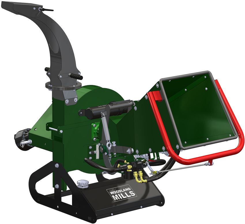
TECHNICAL SPECIFICATIONS
Component WC46 Specification
Drive System PTO
Transport 3-Point Hitch
Minimum HP Required (at PTO) 15 hp
In-Feed System Hydraulic
Hydraulic Oil ISO 32 / AW 32 (ISO 46 / AW 46 for warmer climates)
Hydraulic Tank Volume 4.5 gal [17 L]
Hydraulic Requirement (Tractor) None. Self contained.
PTO Shear Bolt M8 X 50 mm Class 8.8 [5/16-18 X 2 in Grade 5] Hex Bolt
Blade Quantity and Dimensions Four (4); 5.71 X 2.72 X 5/16 in [145 X 69 X 8 mm]
Blade Hardware M10 X 35 mm Flat Head, M10 Lock Nuts - Class 10.9
Infeed Roller Diameter 5-1/4 in [133 mm] at Tooth Tip
Infeed Chute Dimensions 19-5/8 X 18-7/8 in [500 X 480 mm]
Product Weight 550 lb [250 kg]
Product Shipping Weight 625 lb [284 kg]
Discharge
Chute
Infeed
Chute
Front Rear Left Right
WC46-MY2021-EN: Rev B Page 9 of 56 22-Jan-2021WC46 Operator’s Manual i. OVERALL DIMENSIONS—OPERATING STATE WC46-MY2021-EN: Rev B Page 10 of 56 22-Jan-2021
WC46 Operator’s Manual

ii. OVERALL DIMENSIONS—STORED STATE
The discharge chute must be rotated so that it is angled towards the left side of the chipper in
order to allow room for the infeed chute to be flipped upward when the machine is in its stored
state. See section, Storage, for more information.

WC46-MY2021-EN: Rev B                   Page 11 of 56                             22-Jan-2021
WC46 Operator’s Manual

iii. 3-POINT HITCH DIMENSIONS
The wood chipper 3-point hitch is a Category 1 system design to work with tractors in the
horsepower range of 15-30 hp. Top link pin is ¾” (19 mm) diameter and the lift arm pins are
⅞” (22 mm) diameter.

Discharge chute removed from views for clarity.

WC46-MY2021-EN: Rev B                   Page 12 of 56                        22-Jan-2021
WC46 Operator’s Manual

ASSEMBLY
1. TOOLS REQUIRED
                     Tool                                               Specification
 Wrench/Socket                                   13 mm (2X)
 Wrench/Socket                                   16 mm (2X)
 Wrench/Socket                                   17 mm
 Wrench/Socket                                   24 mm or Adjustable Wrench
 Wrench                                          27 mm or Adjustable Wrench
 Hex Key                                         Set of Metric Hex Keys (e.g. 2-10 mm)
 Hacksaw*                                        Any metal-cutting saw (Sawzall, etc.)

* Only if PTO shaft requires trimming. See Trimming the PTO Shaft section for more detail.

WC46-MY2021-EN: Rev B                           Page 13 of 56                                22-Jan-2021
WC46 Operator’s Manual
2. UNPACKING
A. UNBOXING THE CRATE
Unpack the contents of the crate by first cutting the nylon strapping and then remove the
cardboard top and sides. Remove the four (4) M8 hex bolts and nuts located at each bottom
corner of the crate and then lift it off the skid. Discard the crate.
Remove M8 bolts
from each corner
Remove all the loose components from the skid (infeed chute panels, control arm, edge bar,
control arm linkage, discharge chute, discharge chute handles, PTO shaft) and set them to the
side. Leave the wood chipper on the skid.
Assembly
hardware
stored inside
manual tube
Note that the wood chipper is shipped dry (i.e. no hydraulic fluid) from the factory. See the
Technical Specifications section for the volume and type of oil required.
WC46-MY2021-EN: Rev B Page 14 of 56 22-Jan-2021WC46 Operator’s Manual
B. SETTING THE MOUNTING BASE
With the wood chipper still resting on the skid, attach the tractor’s 3-point hitch and raise it a
minimum of 2-¼” (57 mm) above the skid. Slide the skid out from under the wood chipper and
discard it. Remove the four (4) M16 X 40 mm hex bolts and M16 flat washers that connect the
base assembly to the lower flywheel housing.
Hydraulic line ships
disconnected due to
shipping space restrictions
Cap
The disconnected hydraulic line
ships with a red plastic plug
threaded into the open end.
The exposed tank line is fitted
with a red cap. Remove both
the plug and cap before
Plug
proceeding.
WC46-MY2021-EN: Rev B Page 15 of 56 22-Jan-2021WC46 Operator’s Manual
Carefully lower the detached base assembly to the ground. Use the 3-point hitch system to
lower the wood chipper until the top two (2) holes on each side of the mounting base align with
the corresponding holes in the lower flywheel housing. Reattach the four (4) M16 X 40 mm hex
bolts and M16 flat washers. Connect the hydraulic line to the tank that originates from the pump
beneath the lower flywheel housing.
Connect hydraulic
line after moving
base down
WARNING!
The hydraulic tank ships empty from the factory. The user must add
the recommended hydraulic fluid per the table in the section,
Technical Specifications, prior to using the chipper.
WC46-MY2021-EN: Rev B Page 16 of 56 22-Jan-2021WC46 Operator’s Manual
3. INFEED CHUTE
A. TOP PANEL
The wood chipper infeed chute consists of four (4) metal panels that are bolted together. The
first step is bolting the top panel to the lower flywheel housing that forms the hinge. Using the
hardware listed in the table below, assemble the hinge connection. Note that the infeed chute
top panel and hinge bracket come pre-assembled from the factory.
M10 X 15 X
M12 Nylon
2x 20 mm 6x
Flat Washer
Shoulder Bolt
Infeed Chute
2x M10 Lock Nut 1x
Top Panel
WC46-MY2021-EN: Rev B Page 17 of 56 22-Jan-2021WC46 Operator’s Manual
B. SIDE PANELS AND BOTTOM PANEL
With the top panel bolted to the hinge, assemble each side panel to the sides of the top panel
using the M8 X 18 mm button head screws, M8 lock nuts, and M8 fender washers. Use a hex
key for the screws and a socket/wrench for the lock nuts.
M8 X 18 mm
Infeed Chute
6x Button Head 2x
Side Panel
Screw
Infeed Chute
6x M8 Lock Nut 1x
Bottom Panel
M8 X 30 mm
6x Fender
Washer
Install two (2) screws per side along the top edge leaving the last holes empty. Do not fully
tighten the screws. Be sure to assemble the screws with the heads on the inside of the chute
pointing outwards. Next, install the bottom panel using only the first two (2) bolts as shown
below (right). This will allow it to swing up to join the side panels in the coming steps. Note that
the infeed chute bottom panel and latches come pre-assembled from the factory.
WC46-MY2021-EN: Rev B Page 18 of 56 22-Jan-2021WC46 Operator’s Manual C. EDGE BAR The round edge bar is designed to add additional strength to the infeed panels as well as act as a rounded edge, eliminating branches from getting caught on the edge of the infeed panels. To install the edge bar, swing the bottom panel up as shown below and fit the tabs over the outside of the panels. There are two tabs on the side of the round edge bar which will be bolted to the side panels in a later step. WC46-MY2021-EN: Rev B Page 19 of 56 22-Jan-2021
WC46 Operator’s Manual

With the edge bar in place, use the hardware listed below to assemble the panels and the edge
bar. Use a hex key for the button head screws and a socket/wrench for the lock nuts. Install the
remaining thirteen (13) M8 X 18 mm button head screws, M8 lock nuts, and M8 X 30 mm fender
washers as shown below to secure the panels and edge bar in place. Do not fully tighten the
screws.

       M8 X 18 mm                                      M8 X 30 mm
 13x   Button Head                               13x     Fender
          Screw                                          Washer

                                                       Infeed Chute
 13x   M8 Lock Nut                               1x    Round Edge
                                                            Bar

                                 4x Both Sides

WC46-MY2021-EN: Rev B                   Page 20 of 56                             22-Jan-2021
WC46 Operator’s Manual
D. CONTROL ARM
The large red infeed control arm is attached using two (2) M10 X 35 mm button head screws,
M10 lock nuts, and M10 X 26 mm fender washers. Use a hex key for the screws and a socket/
wrench for the lock nuts. The screws pass through the inside of the chute side panel, through
the round edge bar side tabs, and finally through the control handle tabs as shown below.
M10 X 35 mm M10 X 26 mm
2x Button Head 2x Fender
Screw Washer
2x M10 Lock Nut 1x Control Arm
The screw passes through the green chute panel, the grey edge bar side tab, and finally
through the red control arm tab as shown below.
Note that the distance between the unassembled red infeed control arm mounting tabs can be
significantly wider than the infeed chute. This is normal and the arm will flex when compressed.
Assemble one side of the control arm first (but do not fully tighten it), then pull the other end in
and secure that side.
With all of the infeed panel, edge bar, and control arm screws now loosely assembled, tighten
all screws securely.
WC46-MY2021-EN: Rev B Page 21 of 56 22-Jan-2021WC46 Operator’s Manual
E. CONTROL ARM LINKAGE
With the control arm fastened to the infeed chute, the linkage assembly can now be connected
between it and the hydraulic directional control valve.
Control Arm
M10 X 35 mm
1x 1x Linkage
Hex Bolt
Assembly
10 mm Clevis
1x M10 Lock Nut 1x
Pin
Hairpin Cotter
1x
Pin
Fasten the rod end bearing to the red control arm with the M10 X 35 mm hex bolt and M10 lock
nut as shown below.
WC46-MY2021-EN: Rev B Page 22 of 56 22-Jan-2021WC46 Operator’s Manual
On the opposite end of the linkage, secure the linkage to the the hydraulic directional control
valve actuator using the clevis pin and hairpin cotter pin.
Once the linkage has been assembled, ensure both M10 jam nuts are tight.
Tighten both linkage
M10 jam nuts
WC46-MY2021-EN: Rev B Page 23 of 56 22-Jan-2021WC46 Operator’s Manual
4. DISCHARGE CHUTE
The discharge chute assembly comes pre-assembled from the factory. With the hardware listed
below, fasten the discharge chute assembly to the upper flywheel housing first and then
assemble the handles to the discharge chute.
M8 X 25 mm M8 Flat
4x 8x
Hex Head Bolt Washer
M8 X 30 mm
M8 X 20 mm
2x 4x Fender
Hex Head Bolt
Washer
Discharge
M8 X 14 mm
2x 1x Chute
Hex Head Bolt
Assembly
Discharge
4x M8 Lock Nut 2x Chute Handle
with Grip
M8 Lock
4x
Washer
Connect the chute using two (2) M8 X 20 mm hex bolts, two (2) M8 X 14 mm hex bolts, four (4)
M8 lock washers, and four (4) M8 X 30 mm fender washers as shown on the next page.
WC46-MY2021-EN: Rev B Page 24 of 56 22-Jan-2021WC46 Operator’s Manual
Note, when orienting the discharge chute on the upper flywheel housing, the locking pin side of
the chute is assembled to the tractor side of the housing.
M8 X 14 mm
Hex Bolts
Locking pin on tractor
side of housing
M8 X 20 mm
Hex Bolts
Assemble both handles to the chute
using four (4) M8 X 25 mm hex bolts,
eight (8) M8 flat washers, and four (4)
M8 lock nuts.
WC46-MY2021-EN: Rev B Page 25 of 56 22-Jan-2021WC46 Operator’s Manual
TRIMMING THE PTO SHAFT
The wood chipper is shipped with a PTO shaft that can be fitted to most Category 1 tractors.
The PTO shaft may need to be trimmed depending on your tractor and configuration. Follow
the steps below to ensure the PTO shaft is correctly fitted to your tractor.
**Note: the shear bolt end of the PTO shaft mounts to the wood chipper.**
1. Attach the wood chipper to the tractor’s 3-point hitch system. Do not install the PTO shaft.
2. Raise the wood chipper as high as the tractor’s 3-point hitch will allow and measure the
straight-line distance between the locking grooves on the splined shafts as shown below.
Now lower the wood chipper to the ground and measure the distance between the locking
grooves again (the two shafts may or may not align—either is normal as tractor output shaft
height varies). Whichever dimension is shortest, record it as Dim A.
Shear bolt
this end
Wood Chipper
A
Tractor
WC46-MY2021-EN: Rev B Page 26 of 56 22-Jan-2021WC46 Operator’s Manual
3. Verify the distance between the locking pins on the PTO shaft while in the compressed state
(Dim B) as shown in the image below. It should measure 29-7/16 in [747 mm].
B
4. If Dim A is at least 1 in [25 mm] longer than Dim B, the PTO shaft does not require
trimming. It is recommended the shaft not be used if there is less than 6 in [150 mm] of
overlap between the two halves of the PTO shaft when the equipment is in the operating
position.
5. If Dim B is longer than Dim A, the PTO shaft will require trimming. Use this equation to
calculate the correct amount to trim:
(B - A) + 1 inch = C (Amount to Trim)
6. Once C has been calculated, trim that amount from BOTH halves of the PTO shaft safety
cover first, then trim the same amount from both shafts. This will ensure the safety cover on
each end remains a few inches back from the ends of the shafts, otherwise PTO shaft
reassembly could be difficult.
7. After trimming both halves of the PTO shaft, use a file to remove any burrs or sharp edges
and slide the halves back together, ensuring they telescope in-and-out freely. The PTO
shaft is now ready to connect the wood chipper to the tractor for operation.
Remove burrs from Remove burrs from
outer edge of inner inner edge of outer
telescoping shaft telescoping shaft
after trimming after trimming
WC46-MY2021-EN: Rev B Page 27 of 56 22-Jan-2021WC46 Operator’s Manual
OPERATION
1. PRE-START UP CHECKLIST
i. Fill the hydraulic tank with hydraulic oil per the table below:
Capacity
Model Hydraulic Oil
Gallons (gal) Litres (L)
WC46 4.5 17
ISO 32, ISO 46,
WC68 5 18.9
AW 32, AW 46
WC88 5 18.9
ii. Attach the wood chipper to your tractor and take the appropriate measurements to trim
the PTO shaft. Refer to the “TRIMMING THE PTO SHAFT” section of the operator’s
manual for detailed instructions.
**Note: Failure to do so may result in severe damage to the implement and is not
covered under warranty.**
iii. Ensure the bed plate gap is set to within 1/16—1/8 in [1.5—3 mm] between it and the
blades. Refer to “SETTING THE BED PLATE GAP” in the operator’s manual for
detailed instructions.
iv. The wood chipper has several bearings fitted with Zerk fittings for greasing. The PTO
shaft is fitted with two (2) Zerk fittings, one on each yoke. The PTO shaft and all
bearings come pre-greased and do not require greasing on initial start-up. Refer to the
“GREASING BEARINGS AND PTO SHAFT” section of the operator’s manual for
detailed maintenance instructions.
WC46-MY2021-EN: Rev B Page 28 of 56 22-Jan-2021WC46 Operator’s Manual
2. START UP
The following steps in the sub-section below (a. through i.) are a summarization of the steps
necessary to safely and properly operate the wood chipper. Please follow the references to
other sections that provide further detail into the step being performed.
a. Place the tractor transmission in neutral, set the parking brake, then turn the tractor
engine off.
b. Connect the 3-point hitch linkages to the wood chipper and secure them with linch
pins.
c. Adjust the top link of the 3-point hitch so that the wood chipper sits level.
d. Connect the PTO shaft to the tractor with the shear bolt end of the PTO on the wood
chipper. Make sure the PTO safety chains are attached to both the tractor and the
wood chipper to keep the protective PTO safety cover from rotating.
e. Rotate the discharge chute towards a safe direction and lock it in place with the spring-
loaded latch and indexing holes. Adjust the chip deflector to the desired position
based on how far they should be thrown.
f. Push the red control arm all the way in until it stops, then pull it out one click to ensure
the infeed roller is in the neutral position.
g. Start the tractor engine and hold the engine RPM’s at a strong idle. Engage the PTO
slowly. If the tractor is running at a high speed when the PTO is engaged, you could
damage the hydraulic pump belt or break the shear bolt on the PTO shaft. After the
rotor is spinning freely increase the tractor RPM’s until the PTO speed is 540 RPM.
Most tractor tachometers commonly indicate this with a line and/or text.
h. Pull the red control arm all the way out until it stops (forward position). This will start
the infeed roller rotating. Set the infeed roller control to the desired speed.
i. With the wood chipper now running and the infeed roller rotating, it is safe to begin
chipping. Start by feeding smaller diameter branches until better acquainted with the
machine and its operation. Once comfortable, begin feeding in larger pieces. Adjust
the infeed roller control as necessary to regulate the infeed rate of the branches.
WARNING!
To avoid serious injury or death, do not chip brush containing
embedded foreign objects such as nails, wire, metal fragments, etc.
The operator and any assistants must always stay clear of the infeed
chute of the wood chipper whenever it is running.
WC46-MY2021-EN: Rev B Page 29 of 56 22-Jan-2021WC46 Operator’s Manual
3. INFEED ROLLER CONTROL
The wood chipper infeed roller speed control valve is located to the right of the infeed chute.
Rotating the arm as shown in the pictures below will increase or decrease the speed of the
infeed roller. The number “0” (left image) represents no infeed roller rotation while “10” (right
image) represents full speed.
Position “0” Position “10”
The infeed roller can be set to three (3) different rotation settings—forward, neutral and reverse
—by pushing or pulling the red control arm. The forward position pulls branches into the wood
chipper; neutral stops the roller from rotating; and reverse pushes the branches back out the
wood chipper towards the operator. The diagram below illustrates the 3 positions:
Directional
Control Valve Control Arm
ard
Forw
erse tral
Rev Neu
To change the speed of the infeed roller, place the red control arm in the neutral position. This
stops the infeed roller from rotating. The speed control valve can now be moved to the desired
position/speed. Reengage the infeed roller via the control arm.
See maintenance section, ADJUSTING THE RED CONTROL ARM, if the control arm feels too
loose or stiff, or if it falls into neutral or reverse unexpectedly.
WC46-MY2021-EN: Rev B Page 30 of 56 22-Jan-2021WC46 Operator’s Manual
4. DISCHARGE CHUTE
To rotate the discharge chute, push down all the way on the spring-loaded locking pin and twist
it 90° to temporarily lock it in the open position. The discharge chute is now free to rotate a full
360°. Using the handles, rotate it to the desired position and then twist the locking pin back 90°
so that it extends into the closest locking hole to secure the chute in position.
The chip deflector easily adjusts to regulate the distance the chips are thrown. Rotate the
handle counterclockwise to loosen the deflector, adjust the deflector to the desired angle, then
re-tighten the handle by rotating it clockwise to secure the deflector.
Loose
Tight
WC46-MY2021-EN: Rev B Page 31 of 56 22-Jan-2021WC46 Operator’s Manual
5. CHIPPING
Keep your face and body away from the feed opening. Do not over reach. Keep proper
balance and footing at all times. The wood chipper is designed to chip a variety of materials into
a more readily decomposing or handled condition. The following guidelines can be used to help
you get started. Please read and follow all safety instructions in this manual. Failure to operate
the wood chipper in accordance with the safety instructions MAY RESULT IN PERSONAL
INJURY!
• Ensure the wood chipper is at full operating speed before starting to chip material.
• Select limbs up to 4” (102 mm) in diameter. Trim side branches that cannot be bent
enough to feed into the wood chipper infeed chute. Hold small diameter branches in a
bundle and feed simultaneously.
• Feed brush from the side of the infeed chute rather than from the front. Step aside to
avoid being hit by brush moving into the wood chipper.
• Never lean into the infeed chute or extend any parts of your body inside the infer chute to
push objects further into the wood chipper. Use another stick or branch.
• Do not use hand tools to push brush into the wood chipper. They can go through the
wood chipper and cause injury or damage to the wood chipper.
• Place branches, butt end first, into the wood chipper infeed chute until it contacts the
infeed roller. Once the infeed roller makes contact with the branches, it will pull the
material inwards.
• NOTE: The wood chipper blades dull with use and require periodic sharpening and
sometimes replacing. Refer to the section under service and maintenance, "Sharpening
Wood Chipper Blades,” for further instructions.
6. STOPPING
Do not leave the wood chipper unattended or attempt any inspection/service unless the PTO is
disengaged and the tractor engine is turned off. Allow time for the wood chipper to come to a
complete stop. To stop the wood chipper, follow the steps below:
1. Move the tractor throttle to the SLOW/IDLE position.
2. Disengage the PTO lever and turn off the tractor engine.
3. Allow time for the wood chipper to come to a complete stop.
NOTE: The flywheel continues to spin for some time after the engine or tractor has been
turned off. The flywheel has stopped spinning when noise and/or machine vibration are
no longer detectable. The PTO shaft will also no longer be spinning.
WC46-MY2021-EN: Rev B Page 32 of 56 22-Jan-2021WC46 Operator’s Manual
MAINTENANCE
REPLACING BLADES
Follow these steps when replacing blades. The WC46 wood chipper uses four (4) reversible
hardened steel blades. Each blade is 5.71 X 2.72 X 5/16” (145 X 69 X 8 mm) in size.
1. If installed, disconnect the PTO shaft from the tractor for safety.
2. Open the upper flywheel housing using a 24 mm socket/wrench by removing the M16 X
40 mm bolt and flat washer securing the upper and lower housings together.
3. With the flywheel exposed, manually rotate it so that one of the four (4) locking holes in
the flywheel (near the front of the blade) approximately lines up with the flywheel lock pin
at the rear of the housing. Remove the small locking pin from the flywheel lock pin and
flip the flywheel lock pin around 180°, passing it through the housing and into the locking
hole in the flywheel. Reinstall the smaller locking pin to the flywheel lock pin.
Locking Hole Flywheel Lock Pin Flip Flywheel
Lock Pin 180°
Locking Pin
Belt/pulley shroud removed from images for clarity.
WC46-MY2021-EN: Rev B Page 33 of 56 22-Jan-2021WC46 Operator’s Manual
4. Remove the three (3) M10 X 35 mm flat head bolts and M10 lock nuts that fasten the
blade to the flywheel using a 6 mm hex key on the bolts and a 17 mm socket/wrench on
the lock nuts. Take care not to drop the hardware into the lower flywheel housing.
However, should this occur, a telescoping pen magnet can be used to retrieve them.
5. Repeat Steps 3 & 4 above to remove the remaining three blades. If this is the first time
the blades have been removed following either the original wood chipper purchase or a
recent blade sharpening, the blades can be reversed to utilize the other cutting edge.
Or, the entire blade can be removed and sharpened or it can be replaced with a new
blade. Torque the M10 X 35 mm flat head bolts to 40-45 ft•lb (54-60 N•m) when
installing blades. Always replace the M10 lock nuts with a new set when changing or
reversing blades. Refer to section, Blade Sharpening for blade sharpening instructions
6. Once the blades have been reversed or new blades installed, proceed to section,
Setting the Bed Plate Gap, to properly set the spacing between the blades and bed
plate.
WC46-MY2021-EN: Rev B Page 34 of 56 22-Jan-2021WC46 Operator’s Manual
BLADE SHARPENING
The wood chipper blades will dull, making chipping difficult and cause your tractor to labour. It
is recommended to sharpen the blades every 25-50 hours of operation. The WC46 wood
chipper uses four (4) hardened steel blades. The blades are reversible and can be sharpened
on both sides. Follow the below steps to sharpen the blades.
1. Follow the steps from the previous section, Replacing Blades, to safely remove the
blades from the flywheel.
2. Hand-grind the angled edges of the blade at 33° (see diagram below) using a whetstone
or have them sharpened by a professional. A pedestal style bench grinder will likely
yield poor results if not used properly. If sharpened quickly or aggressively on a bench
grinder, the blade edge can get too hot and change colour, thus removing the heat
treating-properties from the steel. Use short grinding times and cool frequently with
water. Remove an equal and consistent amount of material from each blade to maintain
proper balance when reassembled to the flywheel.
33° 33°
Blade Profile
3. Reinstall the sharpened blades on the flywheel and torque the M10 X 35 mm flat head
bolts to 40-45 ft•lb (54-60 N•m). Always replace the lock nuts with new hardware when
changing or reversing the blades.
4. Once the blades have been sharpened, proceed to the next section, Setting the Bed
Plate Gap, to properly set the spacing between the newly sharpened blades and the bed
plate.
WC46-MY2021-EN: Rev B Page 35 of 56 22-Jan-2021WC46 Operator’s Manual
SETTING THE BED PLATE GAP
The bed plate (also known as the anvil plate) is located on the left side of the flywheel housing
(when facing the infeed chute). For ideal chipping performance, the gap between the bed plate
and the blades should be set to 1/16-1/8” (1.5-3 mm). Follow the steps below to set the gap
properly. Failure to set the proper gap can lead to poor chipping performance and/or clogging.
Bed Plate
1. If installed, disconnect the PTO shaft from the tractor for safety.
2. Open the upper flywheel housing using a 24 mm socket/wrench by removing the M16 X
40 mm bolt and flat washer securing the upper and lower housings together.
3. With the flywheel exposed, manually rotate it so that the first blade lines up with the bed
plate and note the gap between them. Use a flash light for better viewing if necessary.
Repeat this process for the remaining three blades, noting which blade is closest. Use
this blade to set the bed plate gap.
WC46-MY2021-EN: Rev B Page 36 of 56 22-Jan-2021WC46 Operator’s Manual
Flywheel
1/16–1/8” Blade
1.5–3.0 mm
Bed Plate
4. Loosen the three (3) M10 X 25 mm hex bolts securing the bed plate to the lower flywheel
housing so the bed plate is free to slide in and out. This movement will increase or
decrease the gap between the bed plate and the cutting edge of the blade. Slide the
bed plate by gripping the knob and adjust its position so that it is within 1/16‑1/8” (1.5‑3.0
mm) of the cutting edge of the blade. Ensure the gap is uniform along the entire edge of
the blade.
5. Torque the three (3) M10 X 25 mm bed plate hex bolts to 40 ft•lb (54 N•m) once the gap
has been set correctly.
6. Rotate the flywheel by hand and note the gap at each blade. Again, the gap should be
no more or less than 1/16‑1/8” (1.5‑3.0 mm) at each blade edge.
7. Close the upper flywheel housing and secure it to the lower housing by reinstalling the
M16 X 40 mm bolt and flat washer.
WC46-MY2021-EN: Rev B Page 37 of 56 22-Jan-2021WC46 Operator’s Manual
ADJUSTING THE HYDRAULIC PUMP BELT TENSION
Check the condition and tension of the hydraulic pump belt after every 30 hours of operation.
The belt is self-tensioning via an extension spring. The amount of tension can be adjusted by
following these steps:
1. If installed, disconnect the PTO shaft from the wood chipper for safety and to allow
rotation of the belt and pulleys.
2. Check the belt tension by pressing on it with your finger (see “Checking Belt Tension”
below). There should not be any free slack in the belt. It should be under firm tension.
3. If the belt requires more tension, the eyebolt connected to the spring can be adjusted by
moving the M8 hex nuts (see “Adjusting Belt Tension” below). This will stretch the spring
and increase the belt tension until the proper tension is achieved.
Checking Belt Tension Adjusting Belt Tension
WC46-MY2021-EN: Rev B Page 38 of 56 22-Jan-2021WC46 Operator’s Manual
REPLACING THE HYDRAULIC PUMP BELT
Check the condition and tension of the hydraulic pump belt after every 30 hours of operation. If
the infeed roller is not rotating, or it is rotating slowly, the belt could be slipping. A squealing
noise may also be heard. In either case, these conditions can occur due to a worn belt or
improper belt tension (see the previous section, Adjusting the Hydraulic Pump Belt Tension).
To replace a worn belt, follow the steps below:
1. If installed, disconnect the PTO shaft from the wood chipper for safety.
2. Loosen the lower M8 hex nut that secures the eyebolt to the steel bracket until sufficient
tension has been removed from the spring allowing it to be unhooked from the belt
tensioner. The belt tensioner can now be swung up out of the way allowing for removal
of the belt from the pulleys.
Loosen lower
M8 hex nut
Unhook spring from
belt tensioner once
sufficiently loose
3. Install the new belt around the pulleys first and then reinstall the spring. Re-tension the
spring by tightening the lower M8 hex nut on the eyebolt. Refer to the previous section,
Adjusting the Hydraulic Pump Belt Tension, for instructions on how to properly re-
tension the belt.
WC46-MY2021-EN: Rev B Page 39 of 56 22-Jan-2021WC46 Operator’s Manual
ADJUSTING THE RED CONTROL ARM
If the movement of the red control arm feels too stiff or too loose, or if it falls into neutral or
reverse unexpectedly, it can be adjusted via the directional control valve.
Unscrew the plastic cap from the back of the directional control valve (located under the infeed
chute), exposing the jam nut and set screw.
Directional Loosen jam nut
Control Valve
Remove Set screw
plastic cap CW:Stiffen
CCW:Loosen
Loosen the jam nut with a 22 mm [⅞ in] wrench. Use a 6 mm hex key and turn the set screw
clockwise to stiffen the movement of the arm, counter-clockwise to loosen it. Tighten the
jam nut and replace the cap after the control arm movement feels satisfactory.
WC46-MY2021-EN: Rev B Page 40 of 56 22-Jan-2021WC46 Operator’s Manual
GREASING BEARINGS AND PTO SHAFT
The wood chipper has six (6) grease points: two (2) flywheel bearings, one (1) infeed roller
bearing, and three (3) on the PTO shaft. Check each grease point prior to use and add grease
as needed.
**Warning: These grease points come pre-greased from the factory. Do not add grease to
these points on a new wood chipper. Over-greasing can damage the bearing seals.**
Front Flywheel Shaft Bearing Rear Flywheel Shaft Bearing
Infeed Roller Bearing
PTO Shaft U-Joint 1 PTO Shaft U-Joint 2
WC46-MY2021-EN: Rev B Page 41 of 56 22-Jan-2021WC46 Operator’s Manual
STORAGE
When the wood chipper is not in use, it can be stored to utilize a smaller footprint to save space.
Follow these steps to put the wood chipper in its storage state:
1. Disconnect the control bar linkage from the directional control valve and reconnect it to
the tab on the underside of the infeed chute bottom panel.
2. Disengage the two (2) latches on the underside of the infeed chute bottom panel.
3. Rotate the discharge chute so that it is angled towards the left side of the machine.
4. Swing the infeed chute up until it is resting on the swingarm. Tilt the deflector down.
1 2
3 4
WC46-MY2021-EN: Rev B Page 42 of 56 22-Jan-2021WC46 Operator’s Manual
TROUBLESHOOTING
Problem/Issue Possible Causes Resolution Options
1. Infeed roller control set too 1. Increase infeed roller control to a higher value. Refer to
low. page 30.
Brush is feeding 2. PTO RPM below 540. 2. Adjust tractor RPMs to 540 at output.
too slowly 3. Blades are dull. 3. Reverse, sharpen, or replace blades. Refer to page 33
4. Improper bed plate gap. & page 35.
4. Re-set bed plate gap. Refer to page 36.
Brush exiting 1. Blades are dull. 1. Reverse, sharpen, or replace blades. Refer to page 33
discharge chute is 2. Brush is excessively sappy. & page 35.
stringy 2. Clean blades and bed plate.
1. Blades are dull. 1. Reverse, sharpen, or replace blades. Refer to page 33
2. Improper bed plate gap. & page 35.
Excessive
3. PTO RPM below 540. 2. Re-set bed plate gap. Refer to page 36.
clogging
3. Clean blades and bed plate.
4. Adjust tractor RPMs to 540 at output.
Hydraulic pump 1. Belt tension not set 1. Adjust belt tension. Refer to page 38.
belt slipping or properly. 2. Replace belt. Refer to page 39.
squeaking 2. Belt is old/worn.
Excessive noise 1. Bearings not sufficiently 1. Grease bearings. Refer to page 41.
coming from lubricated. 2. Replace bearings. Please contact Woodland Mills for
flywheel bearings 2. Bearings are worn. bearing replacement instructions.
Red control arm 1. Directional control valve not 1. Adjust directional control valve set screw. Refer to
falls into neutral or adjusted properly. page 40.
reverse
WC46-MY2021-EN: Rev B Page 43 of 56 22-Jan-2021WC46 Operator’s Manual PARTS LIST Item Qty Part No. Description 1 1 0001740 BASE 2 1 0001739 HYDRAULIC TANK, 17 L [4.5 gal] 3 1 0001164 HYDRAULIC TANK INTAKE LINE 4 1 0001752 HYDRAULIC INTAKE FILTER, 1/2 NPT 5 1 0004841 O-RING, 50 mm ID / 57 mm OD, 3.5 mm THK 6 1 0005188 OIL SCREEN, 50 mm DIA X 120 mm LG SCREEN 7 1 0005183 OIL SCREEN CAP, 85 mm DIA, M48 X 2 THD 8 1 0005187 GASKET, OIL SCREEN, 55 mm ID 9 1 0005186 GASKET, OIL SCREEN CAP, 48 mm ID 10 1 0005185 RETAINING RING, INTERNAL, 46 mm BORE (48.5 mm GROOVE) 11 1 0001747 LOWER FLYWHEEL HOUSING 12 1 0001711 INNER HINGE, INFEED CHUTE 13 1 0001726 CURTAIN BRACKET 14 2 0001727 CURTAIN 15 1 0001728 CURTAIN PLATE 16 1 0001715 SWINGARM 17 2 0001182 SWINGARM PIVOT BUSHING, 15 mm SHOULDER 18 2 0001732 EXTENSION SPRING, HOOK ENDS, 33 mm OD, 5 mm DIA WIRE, 180 mm LG 19 1 0001179 HYDRAULIC MOTOR ADAPTER PLATE, 6205-2RS BEARING 20 1 0004861 HYDRAULIC MOTOR 21 1 0004846 PARALLEL KEY, 8 X 7 mm, 25 mm LG 22 1 0001717 INFEED ROLLER 23 1 0001729 INFEED ROLLER COVER PLATE 24 1 0001730 BED PLATE, 126 X 103.6 X 9.4 mm 25 1 0001191 KNOB, MULTI-LOBE, 32 mm OD, M8 X 1.25, 30 mm LG, M8 WLD HEX NUT 26 2 0001733 STRIKE PLATE BOLT, 20 mm HEAD DIA, M8 X 1.25 THD 27 2 0001738 3-POINT HITCH PIN, LOWER, M20 X 2.5, 21 mm DIA, 60 mm USEABLE LG 28 1 0001156 3-POINT HITCH PIN, UPPER, 19 mm DIA, 90 mm USEABLE LG 29 3 0004705 LINCH PIN, 10 mm DIA, 38 mm USEABLE LG 30 1 0001744 FLYWHEEL 31 4 0001735 FLYWHEEL BLADE, 145 X 69 X 8 mm 32 1 0001745 FLYWHEEL SHAFT 33 4 0001734 SPACER, 40.6 ID X 46 OD X 1.5 mm THK 34 1 0004849 PARALLEL KEY, 10 X 8 mm, 40 mm LG 35 1 0001736 V-BELT PULLEY, 35 mm SHAFT, 125 mm DIA 36 1 0001731 FLYWHEEL SHAFT COVER, UCFU208 BEARING 37 1 0001795 FLYWHEEL SHAFT COVER PLUG 38 1 0001746 FLYWHEEL LOCK PIN 39 1 0004728 LOCKING PIN, ROUND, 1/4 in DIA, 1-3/8 in USEABLE LG 40 1 0001743 BELT TENSIONER ARM 41 2 0004789 CIRCLIP, 16-24 mm SHAFT (15 mm GROOVE) 42 1 0001692 IDLER PULLEY, SINGLE BEARING, 25 mm WD, 80 mm DIA 43 1 0004816 RETAINING RING, INTERNAL, 40 mm BORE (42.5 mm GROOVE) 44 1 0001192 EXTENSION SPRING, HOOK ENDS, 21 mm OD, 3 mm DIA WIRE, 100 mm LG 45 1 0004869 HYDRAULIC GEAR PUMP, 10 mL/r, KEYED SHAFT 46 1 0004845 PARALLEL KEY, 6 X 6 mm, 32 mm LG 47 1 0001737 V-BELT PULLEY, 18 mm SHAFT, 90 mm DIA 48 1 0004872 DIRECTIONAL CONTROL VALVE WC46-MY2021-EN: Rev B Page 44 of 56 22-Jan-2021
WC46 Operator’s Manual

 Item   Qty   Part No.                                          Description
 49     1     0004875    VARIABLE FLOW CONTROL VALVE, 1/2 in NPT, 0-16 gal/min
 50     2     0001304    LATCH-STYLE TOGGLE CLAMP
 51     1     0001714    INFEED CHUTE TOP PANEL
 52     1     0001716    OUTER HINGE, INFEED CHUTE
 53     2     0001712    INFEED CHUTE SIDE PANEL
 54     1     0001713    INFEED CHUTE BOTTOM PANEL
 55     1     0001723    ROUND EDGE BAR, INFEED CHUTE
 56     1     0001724    CONTROL ARM, INFEED ROLLER
 57     2     0001781    PLASTIC END CAP, 38 mm DIA
 58     1     0001725    LINKAGE ROD, INFEED ROLLER
 59     1     0004834    CLEVIS ROD END, M10 X 1.5 THD, 10 mm ID, 10 mm JAW OPENING
 60     1     0004749    CLEVIS PIN, 10 mm DIA, 24 mm USABLE LG, 30 mm LG
 61     1     0004760    HAIRPIN COTTER PIN, 10-16 mm CLEVIS, 3 mm WIRE DIA
 62     1     0004888    ROD END BEARING, 10 mm, M10 X 1.5 FEM THD
 63     1     0001742    UPPER FLYWHEEL HOUSING
 64     1     0001741    DISCHARGE CHUTE NOZZLE
 65     1     0001172    DISCHARGE CHUTE LOCK PIN ASSEMBLY, 12 mm DIA
 66     1     0001722    DISCHARGE CHUTE
 67     2     0001720    DISCHARGE CHUTE RETAINER PLATE
 68     2     0001718    DISCHARGE CHUTE ROTATION HANDLE
 69     2     0001030    HANDLE GRIP, GROOVED, 26 mm ID, 108 mm LG
 70     1     0001721    DISCHARGE CHUTE DEFLECTOR
 71     1     0001786    ADJUSTABLE HANDLE, 78 X 54 mm, M10 X 1.5
 72     1     0001655    MANUAL TUBE
 73     8     0005124    FITTING, ADAPTER, 1/2 in NPT MALE TO 7/8-14 UNF MALE
 74     3     0005115    FITTING, ELBOW, 90°, 1/2 NPT TO 7/8-14 THD
 75     1     0004911    FITTING, TEE, 1/2 NPT TO 7/8-14 (2X)
 76     3     0003297    HYDRAULIC LINE ASSEMBLY, STR AND ELB FITTINGS, 350 mm LG
 77     1     0003298    HYDRAULIC LINE ASSEMBLY, STR AND ELB FITTINGS, 500 mm LG
 78     1     0003300    HYDRAULIC LINE ASSEMBLY, STR AND ELB FITTINGS, 600 mm LG
 79     1     0003302    HYDRAULIC LINE ASSEMBLY, STR FITTINGS, 1000 mm LG
 80     1     0003303    HYDRAULIC LINE ASSEMBLY, STR AND ELB FITTINGS, 1450 mm LG
 81     1     0001761    PTO SHAFT W/ SHEAR BOLT, TRIMMABLE, 31-38 in (790-973 mm)
 81.1   1     0003069    COVER/RETAINING CLIP KIT, PTO SHAFT W/ SHEAR BOLT
 81.2   1     0003073    RETAINING CLIP KIT, PTO SHAFT W/ SHEAR BOLT
 81.3   1      HDW       HEX BOLT, M8 X 1.25, 50 mm LG, 22 mm LG THD
 81.4   1      HDW       LOCK NUT, M8 X 1.25
 82     1      BX41      V-BELT, COGGED, BX41
 83     1     6203-2RS   BALL BEARING, SEALED, 6203-2RS, 17 mm BORE, 40 mm OD, 12 mm WIDE
 84     1     6205-2RS   BALL BEARING, SEALED, 6205-2RS, 25 mm BORE, 52 mm OD, 15 mm WIDE
 85     2     UCF208     FLANGE BEARING, SQ, 4-BOLT, UCF208, 40 mm BORE, 102 mm C-C
 86     1     UCFL204    FLANGE BEARING, OVAL, 2-BOLT, UCFL204, 20 mm BORE, 90 mm C-C
 87     4      HDW       HEX BOLT, M6 X 1, 10 mm LG
 88     4      HDW       HEX BOLT, M6 X 1, 20 mm LG
 89     2      HDW       HEX BOLT, M6 X 1, 60 mm LG, 18 mm LG THD
 90     2      HDW       HEX BOLT, M8 X 1.25, 14 mm LG
 91     2      HDW       HEX BOLT, M8 X 1.25, 16 mm LG
 92     4      HDW       HEX BOLT, M8 X 1.25, 20 mm LG
 93     4      HDW       HEX BOLT, M8 X 1.25, 25 mm LG
 94     6      HDW       HEX BOLT, M8 X 1.25, 35 mm LG
 95     4      HDW       HEX BOLT, M8 X 1.25, 40 mm LG

WC46-MY2021-EN: Rev B                     Page 45 of 56                                 22-Jan-2021
WC46 Operator’s Manual

 Item   Qty   Part No.                                      Description
 96     1      HDW       HEX BOLT, M8 X 1.25, 45 mm LG
 97     2      HDW       HEX BOLT, M8 X 1.25, 55 mm LG, 22 mm LG THD
 98     3      HDW       HEX BOLT, M10 X 1.5, 25 mm LG
 99     3      HDW       HEX BOLT, M10 X 1.5, 35 mm LG
 100    2      HDW       HEX BOLT, M12 X 1.75, 25 mm LG
 101    2      HDW       HEX BOLT, M12 X 1.75, 30 mm LG
 102    2      HDW       HEX BOLT, M12 X 1.75, 50 mm LG
 103    1      HDW       HEX BOLT, M12 X 1.75, 160 mm LG, 30 mm LG THD
 104    5      HDW       HEX BOLT, M16 X 2, 40 mm LG
 105    2      HDW       HEX BOLT, M16 X 2, 80 mm LG, 38 mm LG THD
 106    3      HDW       EYEBOLT, DIN444, M10 X 1.5, 120 mm LG
 107    19     HDW       BUTTON HEAD SCREW, M8 X 1.25, 18 mm LG
 108    2      HDW       BUTTON HEAD SCREW, M10 X 1.5, 35 mm LG
 109    2      HDW       BUTTON HEAD SCREW, M12 X 1.75, 50 mm LG
 110    4      HDW       SCREW, PPH, M5 X 0.8, 14 mm LG
 111    11     HDW       SCREW, PPH, M6 X 1, 10 mm LG
 112    4      HDW       SCREW, PPH, M6 X 1, 16 mm LG
 113    12     HDW       SCREW, HFH, M10 X 1.5, 35 mm LG, CL 10.9
 114    8      HDW       SCREW, HFH, M12 X 1.75, 40 mm LG
 115    4      HDW       SCREW, HFH, M14 X 2, 60 mm LG
 116    4      HDW       SHCS, M5 X 0.8, 14 mm LG
 117    4      HDW       SHCS, M6 X 1, 20 mm LG
 118    1      HDW       SHCS, M10 X 1.5, 25 mm LG
 119    2      HDW       SHLDR SCREW, HEX HEAD, 11 X 15 mm LG SHLDR, M10 X 1.5 X 20 mm LG THD
 120    2      HDW       SET SCREW, FLAT TIP, M6 X 1, 6 mm LG
 121    1      HDW       SET SCREW, FLAT TIP, M6 X 1, 8 mm LG
 122    4      HDW       SET SCREW, FLAT TIP, M8 X 1.25, 10 mm LG
 123    4      HDW       FLAT WASHER, M5
 124    28     HDW       FLAT WASHER, M8
 125    3      HDW       FLAT WASHER, DIN7349, M10, 4 mm THK
 126    6      HDW       FLAT WASHER, M12
 127    6      HDW       FLAT WASHER, M12, 25.1 mm OD, NYLON
 128    5      HDW       FLAT WASHER, M16
 129    23     HDW       FENDER WASHER, M8, 30 mm OD
 130    1      HDW       FENDER WASHER, M10, 22 mm OD
 131    3      HDW       FENDER WASHER, M10, 26 mm OD
 132    2      HDW       FENDER WASHER, M12, 37 mm OD
 133    4      HDW       SPLIT LOCK WASHER, M5
 134    16     HDW       SPLIT LOCK WASHER, M6
 135    6      HDW       SPLIT LOCK WASHER, M8
 136    4      HDW       SPLIT LOCK WASHER, M10
 137    1      HDW       HEX NUT, M10 X 1.25
 138    7      HDW       HEX NUT, M10 X 1.5
 139    2      HDW       HEX NUT, M16 X 2
 140    10     HDW       LOCK NUT, M6 X 1
 141    36     HDW       LOCK NUT, M8 X 1.25
 142    19     HDW       LOCK NUT, M10 X 1.5
 143    17     HDW       LOCK NUT, M12 X 1.75
 144    4      HDW       LOCK NUT, M14 X 2
 145    2      HDW       LOCK NUT, M20 X 2.5
 146    4      HDW       LOCK NUT, FLANGED, M8 X 1.25

WC46-MY2021-EN: Rev B                    Page 46 of 56                                22-Jan-2021
WC46 Operator’s Manual

EXPLODED ASSEMBLY VIEWS
COMPLETE ASSEMBLY

WC46-MY2021-EN: Rev B    Page 47 of 56   22-Jan-2021
WC46 Operator’s Manual

BASE

WC46-MY2021-EN: Rev B    Page 48 of 56   22-Jan-2021
WC46 Operator’s Manual

LOWER FLYWHEEL HOUSING

WC46-MY2021-EN: Rev B    Page 49 of 56   22-Jan-2021
WC46 Operator’s Manual

FLYWHEEL

WC46-MY2021-EN: Rev B    Page 50 of 56   22-Jan-2021
WC46 Operator’s Manual

INFEED CHUTE

WC46-MY2021-EN: Rev B    Page 51 of 56   22-Jan-2021
WC46 Operator’s Manual

DISCHARGE CHUTE

WC46-MY2021-EN: Rev B    Page 52 of 56   22-Jan-2021
WC46 Operator’s Manual

HYDRAULIC LINES

WC46-MY2021-EN: Rev B    Page 53 of 56   22-Jan-2021
22-Jan-2021
                                     Retaining Clip Kit [Item 81.2] is included with Cover/Retaining
                                                            Clip Kit [Item 81.1].
                                     Order Item 81.1 if covers are needed as clips are automatically
                                           included. Order Item 81.2 if only clips are needed.

                                                                                                                                                            Page 54 of 56
                                                                                                                                                            WC46-MY2021-EN: Rev B
WC46 Operator’s Manual

                         PTO SHAFT

                                                                                           Shear Bolt [Item 81.3] is a partially threaded M8 X 1.25 X 50
                                                                                           mm Class 8.8 hex bolt with an M8 X 1.25 lock nut [Item 81.4].
                                                                                            Shear Bolt inch equivalent: partially threaded 5/16-18 X 2 in
                                                                                                     Grade 5 hex bolt with a 5/16-18 lock nut.
WC46 Operator’s Manual NOTES WC46-MY2021-EN: Rev B Page 55 of 56 22-Jan-2021
WC46 Operator’s Manual

WC46-MY2021-EN: Rev B    Page 56 of 56   22-Jan-2021
This page intentionally left blank.
You can also read