Holborn Gas Conventional Flue - Installation, Servicing and User Guide - PLEASE RETAIN THIS GUIDE FOR FUTURE REFERENCE - Arada Stoves
←
→
Page content transcription
If your browser does not render page correctly, please read the page content below
Holborn Gas
                 Conventional Flue

    Installation, Servicing and User Guide

   PLEASE RETAIN THIS GUIDE FOR FUTURE REFERENCE

         For use in GB      & IE (United Kingdom and Ireland)
BS EN 613: 2001 + A1: 2003 +C1:2008

BK742 SPECIFIC Rev 03        ISSUE DATE : 28/06/2021
                                                          19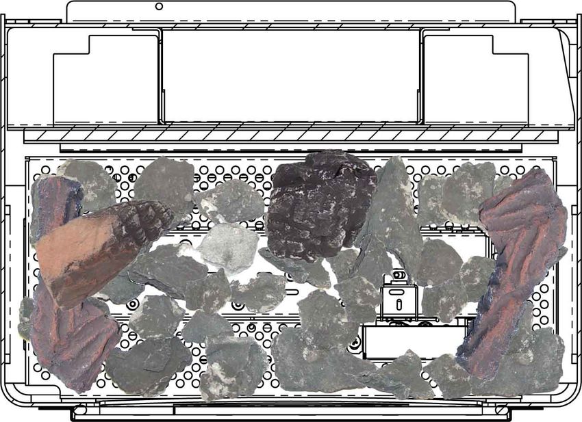
Holborn Gas CF Stove Installation and Servicing

                                        Holborn Gas Stove

 Congratulations on the purchase of your new Arada stove!

 Your stove is built to the highest standard of craftsmanship using the
 best materials and the most modern equipment available. It is a highly efficient
 and sophisticated piece of machinery and when properly installed and
 operated it should provide a lifetime of heating satisfaction.

 Should you have any questions about your stove which are not covered by this
 manual, please contact the Arada retailer in your area, call our technical
 support department on +44 (0)1297 632052 or visit our website
 www.aradastoves.com which offers a wealth of information on how to care for,
 and get the best from your stove.

 Please ensure that you read these instructions in full and understand them
 before operating your stove.

 Arada has a policy of continuous product development and therefore we
 reserve the right to amend specifications without prior notice. Due to printing
 cycles, items or options may be described before they are generally available
 or after they have ceased. Please check with your retailer or dealer if you are
 unsure about any aspect of your stove, its installation or correct use.

Page 2                                                                         BK742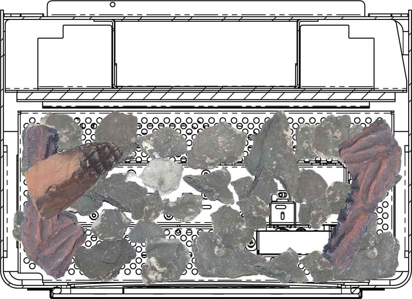
Holborn Gas CF Stove Installation and Servicing

                       Installation & Service

        Contents
        Installation & Service
        1 Appliance Information
        1.1 Conditions Of Installation…………………………………....….. 4
        1.2 Flue & Chimney Suitability……………………………….. ……. 5

        2 Installation
        2.1 Hearth……………………………………………………………..                           6
        2.2 Siting ……………………………………………………………...                         6
        2.3 Flue Connection ………………………………………………….                      7
        2.4 Ventilation ………………………………………………………..                       7
        2.5 Gas Connection ………………………………………………….                       7
        2.6 Placement Of The Ceramic Logs……………………………….                8-12
        2.7 Operating Instructions …………………………………………..                 13-16
        2.8 Spillage ……………………………………………………………                          17
        2.9 Customer Education …………………………………………….                     17

        3 Servicing Instructions
        3.1 Replacement Parts………………………………………………. 17

                       User Instructions
        4 Important Information
        4.1 Important Information For Use Of Appliance………………….        19
        4.2 Layout Of Ceramic Logs…………………………………………                    19-23
        4.3 Operating Control Locations…………………………………….                24
        4.4 Battery Replacement…………………………………………….                     25
        4.5 Fire Control Valve—Red Indicator Meaning………………….          25
        4.6 Using The Remote Display Handset…………………………..              26-27
        4.7 Trouble Shooting / FAQ …………………………………………                   27
        4.8 Remote Display Handset Optional Features…………………..         28-32

        5 Guarantee
        5.1 Guarantee………………………………………………………...                         33
        5.2 Terms & Conditions………………………………………………                      33-34
        5.3 General…………………………………………………………….                           34
        5.4 Notes……………………………………………………………….                            35

BK742                                                                                  Page 3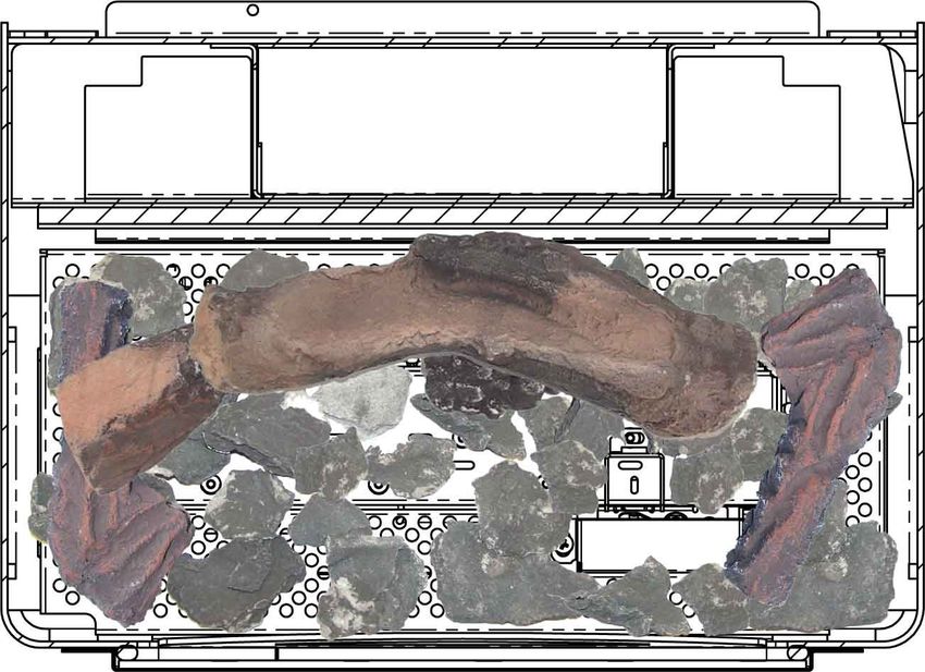
Holborn Gas CF Stove Installation and Servicing

SECTION 1 : APPLIANCE INFORMATION

Model                                                                           Holborn Gas
Gas Type                                                  G20 (Natural Gas)    G31 (Propane)         G30 (Butane)
Supply Pressure (Measured At Test Elbow), (mbar)                  20                 37                   29
Injector (x1)                                              Stereomatic 320     Stereomatic 120     Stereomatic 120
Oxypilot Type                                              Erta PG-82-330      Erta PG-82-350       Erta PG-82-350
Nominal Heat Input (Qn), kW (Gross) Maximum Rate                   5                 4.4                  4.5
Gas Consumption At Maximum Rate, (m3/h)                           0.47              0.157                0.121
Minimum Heat Input, kW (Gross)                                    2.3                1.8                  2.7
Gas Consumption At Minimum Rate, (m3/h)                           0.22              0.061                0.074
Gas Connection                                            8mm Compression     8mm Compression     8mm Compression
Remote Gas Valve                                          TESC01 RF868-15     TESC01 RF868-15     TESC01 RF868-15
Countries Of Destination                                       GB & IE            GB & IE              GB & IE
Efficiency Class                                                   1                  1                    1
Energy Efficiency Index (EEI)                                      B                  D                    C
NOx                                                           95mg/kWh           97mg/kWh             98mg/kWh

1.1 - Conditions Of Installation
Before installation, check that the local distribution conditions, nature of the gas and pressure, and adjustment
of the appliance compatible. It is the law that only a competent person installs all gas appliances ie: a gas
registered installer in accordance with the current edition of the gas safety (installation and use) regulations or
the rules in force, failure to do so could lead to prosecution.
The installer must be gas safe registered.
The installation must also be in accordance with all relevant parts of the local and national buildings
regulations where appropriate, the building regulations (Scotland consolidation) issued by the Scottish
development department, and all applicable requirements of the following standard codes of practice :
         1.     BS 5871 part 1
         2.     BS 6891 installation of gas pipework
         3.     BS 5440 parts 1 & 2 installation of flues and ventilation
         4.     BS 8303 installation of domestic heating appliances
         5.     IS 813 Domestic gas installation (Republic Of Ireland)
No purpose made additional ventilation is normally required for this appliance when         installed in G.B. When
installing in I.E. please consult document IS 813 domestic gas installation, which is issued by the national
standards authority of Ireland, if installing in Northern Ireland please consult local building regulations. In
Scotland, please consult the current edition of the building standards regulations, issued by the Scottish
executive. Any purpose made ventilation must be checked periodically to ensure that it is free from
obstruction.

PLEASE NOTE—The stove is a very heavy appliance and care must be used when lifting and moving, we
recommend 2 people lift following lifting guidelines. Preferably wear gloves when lifting.

Page 4                                                                                                            BK742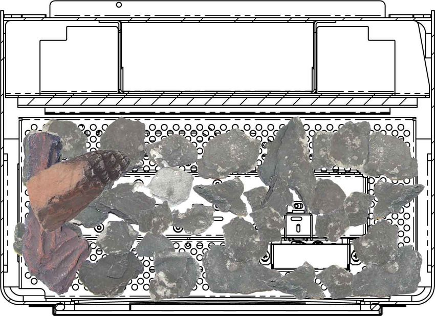
Holborn Gas CF Stove Installation and Servicing

1.2 - FLUE & CHIMNEY SUITABILITY

MINIMUM DIMENSION OF FLUES 125 mm DIAMETER.
MINIMUM EFFECTIVE HEIGHT OF ALL FLUE TYPES 3 METRES.
This appliance is designed for use with conventional brick built or lined chimneys, all flues must conform to the
following minimum dimensions :
Before commencing installation a flue or chimney should be inspected to ensure that all of the following
conditions are satisfied :

1.      Check that the chimney / flue only serves one fireplace and is clear of any obstruction, any dampers or
        register plates must be removed or securely locked in the open position.

2.      Brick / stone built chimneys or any chimney or flue which has been used for an appliance burning fuel
        other than gas must be thoroughly swept.

3.      Any under floor air supply to the fireplace must be completely sealed off.

4.      Ensure that the inside of the chimney / flue is in good condition along its length and check that there is
        no leakage of the smoke through the structure of the chimney / flue during and after the smoke pellet
        test.

5.      Using a smoke pellet check there is an updraft in the chimney / flue and that the smoke can be see
        coming from the terminal / pot outside.
        There must be no leakage of smoke through the structure of the chimney during or after the smoke
        pellet test and it is important to check the inside upstairs rooms adjacent to the chimney / flue.
        Check the chimney pot / terminal and general condition or the brickwork and masonry. If the chimney /
        flue is in poor condition or if there is no up-draught do not proceed with the installation, if there is a
        history of down draught conditions with the chimney / flue, again do not proceed until the fault has been
        fixed.
        A tested and certificated flue terminal or cowl suitable for the relevant flue type should be considered.

6.      A spillage test must always be carried out during commissioning of this appliance.

BK742                                                                                                            Page 5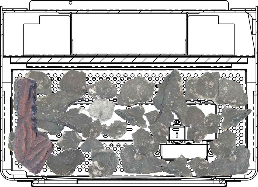
Holborn Gas CF Stove Installation and Servicing

           WARNING

This stove is fitted with a spillage monitoring system consisting of a thermal switch, which shuts the appliance
off in the event of a blocked flue or inadequate flue pull occurring.
The system shall not be adjusted by the installer or shall not be put out of action.
When the spillage monitoring system is required to be replaced, only original manufacturers parts shall be
used.
If the stove switches off for no apparent reason, the appliance should not be used until expert advice is
obtained and the fault rectified.
All surfaces, except the control valve, are working surfaces and become very hot in use. They must not be
touched or any combustible materials put on them.
It is recommended that a fireguard complying to BS 8423 should be fitted for protection of young children or
elderly or infirm persons.

The door assembly has to be removed, to allow access to remove the glass frame assembly.
Allow this to cool before removing, as it will become very hot and is a working surface when the
appliance is in use.

SECTION 2 : INSTALLATION
2.1 - HEARTH

The stove must be installed on a non-combustible hearth with the hearth material being at least 12mm thick,
the hearth must protrude at least 150mm (6”) in front of the stove and be of a size sufficient to accommodate
the stove.

2.2 - SITING
The stove must not be installed in a bathroom.

Clearance from non-combustible material in the fireplace opening must be at least to dimensions in the table
below :

                                                  Non Combustible Material      Combustible Material
                        Position
                                                                      Distance mm
                        Above                              100 mm                     300 mm
                        Back                               50 mm                      300 mm
                        Left                               100 mm                     300 mm
                        Right                              100 mm                     300 mm
NOTE : Fitting the stove any closer to the back may cause nuisance shutdown of the stove as the
        airflow may be compromised and the thermal cut off will operate.

Page 6                                                                                                      BK742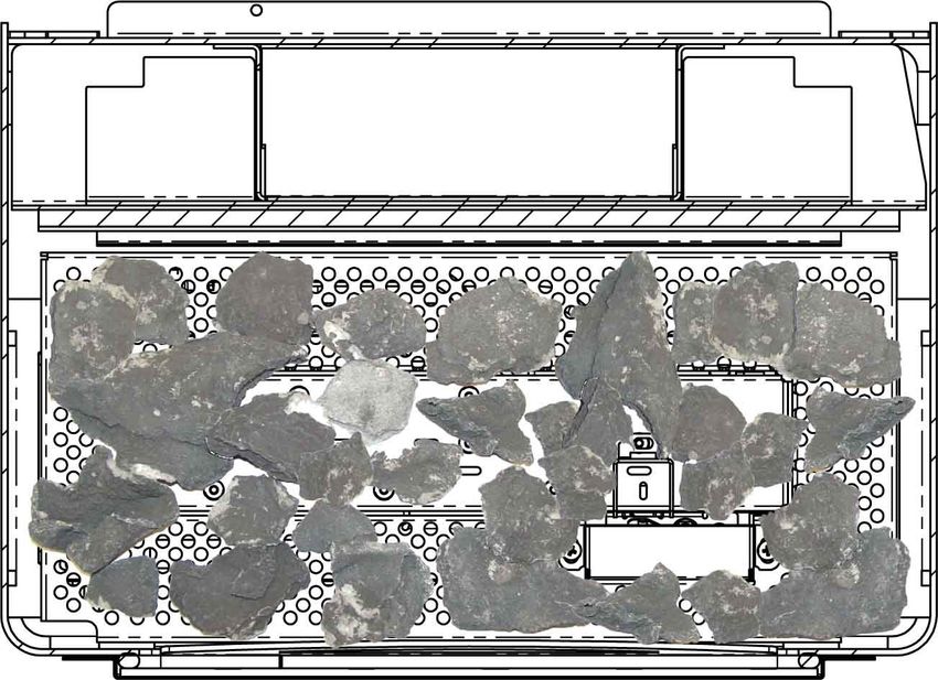
Holborn Gas CF Stove Installation and Servicing

 2.3 - FLUE CONNECTION

 The flue should be at least 3m high and at least 125mm diameter (5”) at no point should there be any
 negative or horizontal gradients in the flue pipe.

 It is recommended that a minimum height of 600mm from the stove before any significant change of
 direction of the flue.

 2.4 - VENTILATION

 Ventilation should be in accordance with national regulations in the UK purpose provided ventilation is not
 normally required BS5871 part 1 and in IE IS813 (IE Only).

 2.5 - GAS CONNECTION

 The gas connection can be made by removing the glass frame assembly; remove all the fixing screws a
 keep safe for future use. Once the frame has been removed, the 4 no. fixings, holding the burner in place
 can be removed and access to the gas inlet elbow can be gained. Once the connection has been made and
 soundness verified the burner can be replaced ensuring correct position and the 4no. fixings replaced.

BK742                                                                                                          Page 7

Holborn Gas CF Stove Installation and Servicing

2.6 - PLACEMENT OF THE CERAMIC LOGS

         WARNING—DO NOT CHANGE THE FUEL BED LAYOUT, THE TYPE OR
         NUMBER OF LOGS.

    Contents Of Log Fuel Effect Kit -

Page 8                                                            BK742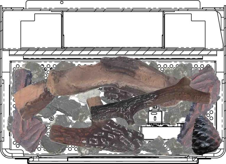
Holborn Gas CF Stove Installation and Servicing

 Fitting Procedure For Log Set Layout -

 STEP 1

  Scatter the bag of embers, evenly over the grate and burner, as shown above, ensuring
  the pilot and pilot shield are left clear from embers as indicated.

 STEP 2

  Place Log 1 as shown above.

BK742                                                                                           Page 9
Holborn Gas CF Stove Installation and Servicing

 STEP 3

 Position Log 2 as shown above. Note, this log rests upon the corner of log 1.

 STEP 4

 Position Log 3 as shown above.

Page 10                                                                          BK742
Holborn Gas CF Stove Installation and Servicing

  STEP 5

  Position Log 4 as shown above, centrally at the rear of the burner.

  STEP 6

  Position Log 5 as shown above, centrally resting upon Logs 2 & 4.

BK742                                                                                            Page 11
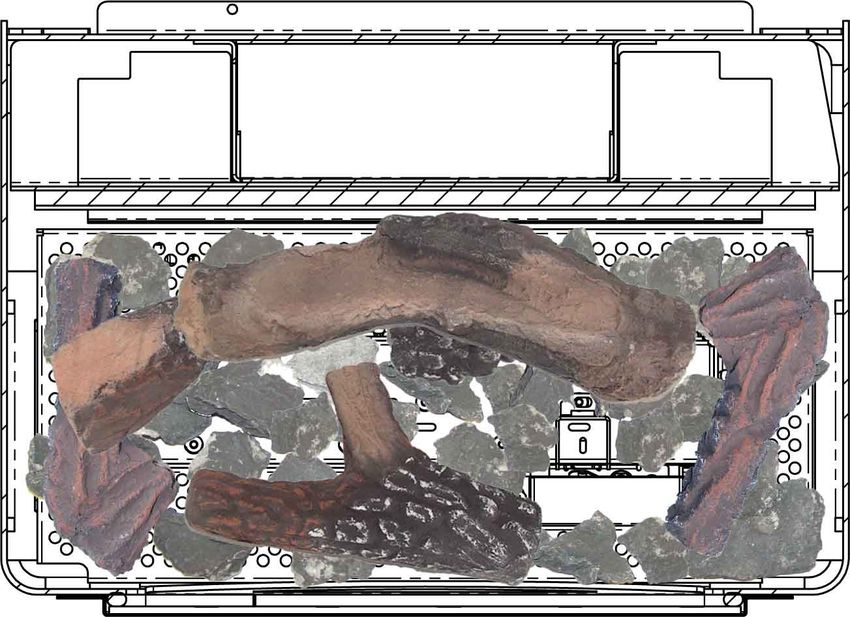
Holborn Gas CF Stove Installation and Servicing

  STEP 7

  Position Log 6 as shown above.

  STEP 8

  Position Log 7 as shown above. Note, this log sits on top of Log 6, Log 5 & Log 3 as
  shown with the arrows.
  The pine cone sits in the RH corner, as shown.

   NOTE : Check that the Pilot is clear and cross lights smoothly to the main burner.

Page 12                                                                                  BK742
Holborn Gas CF Stove Installation and Servicing

 2.7 - OPERATING INSTRUCTIONS

 Below the gas controls, which are situated at the bottom left hand side of the appliance (when viewed
 looking at the appliance door).

                                                                    Battery Compartment Release Lever
        Indicator Light                Power Isolator Switch

   Decrease Flame         Power Button        Increase Flame               Battery Compartment Cover

 Below the remote control handset.

                                                                              Visual Display

                                                                                 Lock / Unlock LED

             Decrease Flame                                               Increase Flame

                                                                         Power Button

BK742                                                                                                      Page 13
Holborn Gas CF Stove Installation and Servicing
+ -
- +
+ -
Replacement of batteries in TESC01 gas control valve -
The TESC01 gas control valve which operates the appliance, is battery powered and will require replacing
periodically; after removing the plastic front cover from the control, the batteries are fitted and positioned as
shown above, always replace the plastic cover once, the new batteries have been fitted.
- +
+ -
Replacement of batteries in the handset -
The remote handset also has batteries as shown above. It is important that the batteries are replaced at least
every 12 months.
Meanings of the red indicator on Fire Control Valve (Handset)
RED INDICATOR MEANING
Permanently Lit Valve tried to light but failed in LOCKOUT E00
Flashing Very Fast Valve Is Busy (Will Not Accept Any Command)
Flashing Once A Second Valve Detects An Error
Permanently Off Valve In Standby Or In A Stable Operation
On Momentarily After Power Up Valve Doing A Self Test
Appears After Pressing Start Indicates Time To Release Pressing The Start
Button
Page 14 BK742Holborn Gas CF Stove Installation and Servicing
INFORMATION ONLY -
NOTE : THE REMOTE CONTROL HANDSET WILL BE SHIPPED PAIRED TO THE GAS
VALVE WITHIN THE BURNER ASSEMBLY—DO NOT ALTER THE PAIRING.
IF FOR ANY REASON THE PAIRING HAS BEEN ALTERED, THEN THE HANDSET
WILL NOT WORK. THE HANDSET WILL NEED TO BE RESET AND PAIRED AGAIN,
PLEASE FOLLOW THE INSTUCTIONS BELOW :
Ensure the handset and the gas valve control have good batteries and the batteries are the correct
polarity as indicated inside both the battery compartments.
Ensure the small slide switch on the top left of the gas valve control is slid to he right (I) position.
Place the handset within half a metre from the gas valve control ( no need to hold it ).
For a new handset the display will show ‘ TESC r5’ or similar text.
To reset a previously paired handset, enter the setup menu and scroll to “C A 0”, when displayed,
change the ‘0’ to ‘1’ using the ‘+’ key and press ‘SET’, the display now shows ‘ TESC r5’ or similar text.
On the gas valve control, simultaneously press the hold the - and + buttons, until the red light on top left
of gas fire control begins to flash rapidly (this will take about 5-8 seconds).
Then immediately as the red light starts to flash, release the - and + buttons and quickly press the
power button. (Note: This button press must be done with 1 second of the red light coming on. If not
done quickly enough, then the above must be repeated until done correctly).
When done correctly, you will hear an audible sound from the handset. Immediately, pick up and grasp
the handset as normal to unlock the key pad and then press and hold the “ SET “ button for around 3 to
5 seconds. The display will show “ “ and you will hear several beeps from the handset
as the pairing has been confirmed.
You know the pairing has taken, as now when holding the handset the green light will be a steady
green ( not flashing when held ). Setting the time & date etc. can now be performed, please see section
4.8 of this guide.
The handset is designed to be not too easily operated by accident for safety
reasons. If for any reason the pairing has been altered, then the handset will not
work.
Note, by removing or replacing the batteries, the pairing will NOT be lost.
BK742 Page 15Holborn Gas CF Stove Installation and Servicing
Hold the handset as shown, wrapping
your hand around the handset touching
both sides. In a second or less the green
unlock light will illuminate, allowing the
buttons to work when pushed.
(NOTE: If the green light is not a constant
green or not lit at all the buttons will not
be operable).
Press and hold in the power symbol button and
release immediately when the word pilot ap-
pears at the bottom left of the display (After
about 1-2 seconds).
The stove will light onto MAX burner setting.
(NOTE: Releasing the power button too soon or
too long after the word pilot is illuminated,
results in the burner not lighting, this is for
safety reasons).
If for any reason the ignition sequence fails to
ignite the burner, the fire control valve
automatically re-attempts the lighting
sequence for a further 2 attempts.
To adjust high and low whilst holding the
handset and green light on press + & - to adjust
for the preferred heat setting.
To Stop the stove, hold handset to unlock the
buttons and then press the power button.
The flame stops almost immediately.
Page 16 BK742Holborn Gas CF Stove Installation and Servicing 2.8 - SPILLAGE Check for clearance of combustion products. Close all doors and windows in the room containing appliance. Turn on appliance and turn to high, leave running for 5 minutes and insert a lighted taper or smoke match into the flue diverter at the rear of the appliance. All the smoke must be drawn into the appliance. If spillage occurs, allow a further 10 minutes and retest. Should spillage occur, seek expert advice. If an extractor fan is situated in the room, the test should be carried out with the fan running, if there is a connected room with an extractor fan the test should be repeated with the fan running and any interconnecting doors open. 2.9 - CUSTOMER EDUCATION Hand these instructions to user. Advise the user until they are fully educated on the use of the stove and the controls. Explain regarding the thermal cut off feature. Advise if this system repeatedly shuts off specialist advice must be consulted. Advise that if the fire goes off for any reason do not re-light for 3 minutes. Advise the stove may give off a slight smell due to the newness and any odours will go after a few hours of use. Advise that the stove must not be used with the glass panel damaged or broken or missing. Advise that no materials like washing, may not be draped over the stove. Recommend regular servicing at least annually. Recommend no extra fuel pieces are added and only authorized spares used. 3.0 - SERVICING INSTRUCTIONS The stove is fitted with a spillage monitoring system consisting of a thermal switch this system is non adjustable and must not be bypassed or put out of action if any parts are replaced it must be with the original manufacturers parts used. 1. Servicing must be carried out regularly and only by a qualified person, ensure the fire is turned off and cold (minimum service must be carried out annually) 2. Open the stove door by unscrewing the handle on the left fully and remove the door can now be opened or even lifted off its hinges then the screws holding the glass can be removed and the glass panel removed. 3. Remove the ceramics carefully. 4. Remove any debris from the burner if necessary vacuum, also clean the pilot or vacuum. 5. If necessary replace pilot (for extended warranty) by removing burner and disconnect gas supply 4 screws can be removed and burner tray removed the thermal cut off switch will have to be disconnected at the rear of the fire to allow the tray to be removed it has to be lifted up on the right hand side and carefully twisted out 6. Replace burner tray and reconnect thermal switch the appliance will not work if this is not done and then replace in reverse order replace glass and stove door. 7. Check the supply pressure and test for spillage 8. The flue will need sweeping periodically for safe use of the appliance. 3.1 REPLACEMENT PARTS Genuine replacement spare parts can be obtained from www.aradastovesandspares.com or your Arada dealer. Please note, that fitting non-official Arada parts to your stove will invalidate the guarantee. BK742 Page 17
Holborn Gas CF Stove Installation and Servicing

                         HOLBORN GAS STOVE
                                             ARADA Ltd
                                          THE FIREWORKS
                                         WEYCROFT AVENUE
                                         AXMINSTER DEVON
                                             EX13 5HU

      NG : APPLIANCE IS CATEGORY I2H FOR
       USE WITH NATURAL GAS AT A SUPPLY
              PRESSURE OF 20 mbar.
      LPG : APPLIANCE IS CATEGORY I3P FOR
   USE WITH LIQUID PETROLIUM GAS AT A SUPPLY
             PRESSURE OF 37 / 29 mbar.

                                           G.B. AND I.E.

           USERS INSTRUCTIONS

      THIS MANUAL MUST BE LEFT WITH
                THE USER

Page 18                                                    BK742
Holborn Gas CF Stove User Guide
SECTION 4. IMPORTANT INFORMATION
4.1 IMPORTANT INFORMATION FOR USE OF APPLIANCE
This stove should not be used for any other purpose than as a room heater and decorative stove,
due to its newness of materials the stove may give off a slight smell for a period of time after
commissioning, this is quite normal and should clear within a few hours of use.
The installation must be in accordance with the national regulations and must be carried by a qualified
installer EG: gas safe engineer.
Under no circumstances should the stove be operated with the glass panel damaged broken or missing.
All surfaces except controls are considered to be working surfaces and will get very hot during and after use,
they must not be touched or any combustible materials, if young children, the elderly or infirm are likely to be
near the stove, a suitable fireguard to BS8423 is recommended.
A combustible shelf may be fitted above the stove providing the shelf protrudes less than 150mm in front of
the stove and there is 300mm clearance above the top of the stove.
Curtains are not recommended above the stove.
Do not drape clothes or any materials over the stove.
The stove must stand on a non-combustible hearth and be at least 12mm thick and sufficient size to
accommodate the stove.
No purpose provided ventilation is normally required but must be in accordance with national regulations in
force.
The fuel bed should be arranged only as shown in these instructions.
Should the stove extinguish for any reason do not relight for a minimum of 3 minutes.
All surfaces, except the control valve are working surfaces and become very hot in use, they must not be
touched or any combustible material be placed upon them.
It is recommended that a fireguard complying to BS 8423 should be fitted for the protection of young children
or elderly or infirm persons.
This stove should be serviced regularly at least annually.
Only replace ceramic parts or any parts of the fuel bed with parts supplied by the manufacturer for this stove
do not change the fuel bed layout from the instructions supplied.
The flue will need sweeping periodically.
If the stove fails to light and the appliance goes to reset, the start button will have to be held for 10 seconds to
clear the remote fault.
THE STOVE IS FITTED WITH A SPILLAGE MONITORING SYSTEM CONSISTING OF
AN ATMOSPHERE SENSING OXYPILOT ASSEMBLY.
THIS SYSTEM IS NOT ADJUSTABLE AND MUST NOT BE PUT OUT OF ACTION.
IF REQUIRED TO BE REPLACED; ONLY ORIGINAL MANUFACTURERS PARTS MUST
BE USED (IF THE STOVE SWITCHES OFF FOR NO APPARENT REASON THE
APPLIANCE SHOULD NOT BE USED UNTIL EXPERT ADVICE IS TAKEN).
BK742 Page 19Holborn Gas CF Stove User Guide 4.2 LAYOUT OF THE CERAMIC LOGS The logs should be positioned as in the pictures below. WARNING : DO NOT CHANGE THE FUEL BED LAYOUT OR THE TYPE OR NUMBER OF LOGS STEP 1 Scatter the bag of embers, evenly over the grate and burner, as shown above, ensuring the pilot and pilot shield are left clear from embers as indicated. STEP 2 Place Log 1 as shown above. Page 20 BK742
Holborn Gas CF Stove User Guide

STEP 3

Position Log 2 as shown above. Note, this log rests upon the corner of log 1.

STEP 4

Position Log 3 as shown above.

BK742                                                                                      Page 21
Holborn Gas CF Stove User Guide

 STEP 5

 Position Log 4 as shown above, centrally at the rear of the burner.

 STEP 6

 Position Log 5 as shown above, centrally resting upon Logs 2 & 4.

Page 22                                                                BK742
Holborn Gas CF Stove User Guide

STEP 7

Position Log 6 as shown above.

STEP 8

 Position Log 7 as shown above. Note, this log sits on top of Log 6, Log 5 & Log 3 as
 shown.
 The pine cone sits in the RH corner, as shown.

  NOTE : Check that the Pilot is clear and cross lights smoothly to the main burner.

BK742                                                                                      Page 23
Holborn Gas CF Stove User Guide
4.3 - OPERATING CONTROL LOCATIONS
The main control of your appliance is the gas fire control valve, which is situated through a cut out in the
front of the body, on the bottom left hand side of the stove, as pictured below.
Access to this cut out is achieved when opening, the decorative fire door.
Power Isolator Battery Compartment
Switch Release Lever
Indicator Light
Decrease Power Increase Battery Compartment FRONT
Flame Button Flame
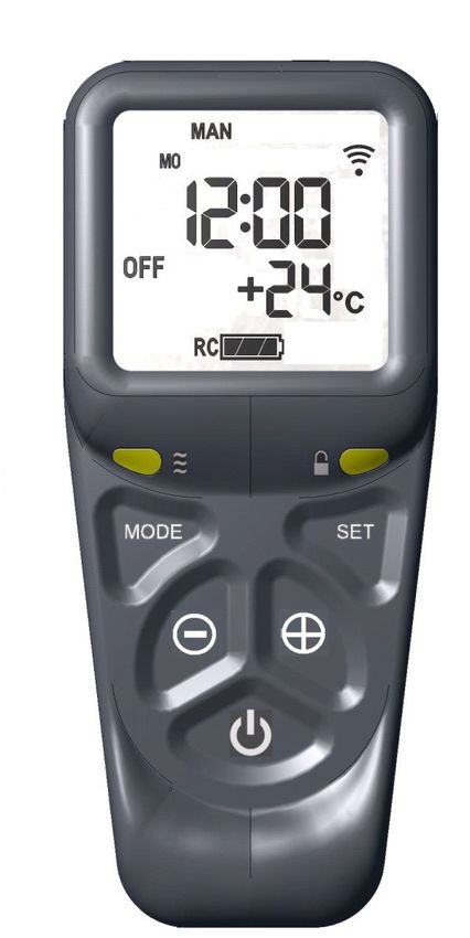
Below the remote control display handset.
Mode—Manual Or Zzz Snooze, Communication Symbol
Thermostat Or Timed (Showing link between fire
control valve and handset)
Day & Time
Gas Burner Status
(Flames Shown When Lit)
Room Temperature
Battery Condition Indicator
(Alternates between RC—
Handset Battery &
FC –Valve Battery) Green Unlock Light
Light Sensor Set Button
(For Backlit Display)
Increase Button
Mode Button
Decrease Button
Power / Standby
Page 24 BK742Holborn Gas CF Stove User Guide
4.4 - BATTERY REPLACEMENT
The gas control valve which operates the appliance is battery powered and require replacing periodically;
after removing the plastic front cover from the control, the batteries (3 No. AA/1.5V LR6) are fitted and
positioned as shown below, always replace the plastic cover, once the new batteries have been fitted.
+ -
- +
+ -
The remote display handset also has batteries as shown below. Again, remove the rear cover and replace
the batteries (2 No. AA/1.5V LR6), observing the correct position as shown.
It is important that the batteries are replaced at least every 12 months, otherwise, the pairing to the
fire control valve will be lost and you will no longer be able to control your appliance via the handset.
A re-pairing of the handset to the fire control valve will be needed to be performed to re-instate the lost
communication between the two components (see page 12).
- +
+ -
4.5 - FIRE CONTROL VALVE—RED INDICATOR MEANING
RED INDICATOR MEANING
Permanently Lit Valve tried to light but failed in LOCKOUT E00
Flashing Very Fast Valve Is Busy (Will Not Accept Any Command)
Flashing Once A Second Valve Detects An Error
Permanently Off Valve In Standby Or In A Stable Operation
On Momentarily After Power Up Valve Doing A Self Test
Appears After Pressing Start Indicates Time To Release Pressing The Start
Button
BK742 Page 25Holborn Gas CF Stove User Guide
4.6 - USING THE REMOTE DISPLAY HANDSET
IMPORTANT USER INFORMATION—AFTER INSTALLATION BY THE GAS SAFE ENGINEER, READ
THIS BEFORE ATTEMPTING TO OPERATE THE APPLIANCE.
NOTE— The handset is supplied paired to the gas control valve. DO NOT ALTER THE PAIRING, this will
only compound any difficulties you may have understanding how to operate the handset.
Read the instructions below.
The handset is designed to be not too easily operated by accident for safety reasons. If for any reason the
pairing has been altered, then the handset will not work. This will require the handset to be reset and paired
again.
Hold the handset as shown, wrapping your hand around the
handset touching both sides, and the green unlock light will
illuminate allowing the buttons to work.
(If the green light is not lit, the buttons will not operate).
Press and hold in the power symbol button and release
immediately as soon as the word pilot appears at the bottom left
of the display (After about 1-2 seconds).
The fire will then light onto MAX burner setting.
(Note: releasing the power button too soon or holding too long
after the word pilot is shown, will result in the fire not starting
correctly).
A pictorial flame symbol is shown in the bottom left hand part of
the display when the burner is running.
To adjust the flame, hold the handset to enable the buttons to
work and press and hold the - button to reduce the flame.
Tapping the button will adjust the flame step by step. Holding
the button will skip through the steps.
Similarly, press the + button to increase the flame as described.
Page 26 BK742Holborn Gas CF Stove User Guide
4.6 - USING THE REMOTE DISPLAY HANDSET—Continued
To STOP the fire, hold handset to unlock the buttons and then
press the power button. The fire will stop without delay.
Wait for the word OFF to appear on the display (LH Side) before
trying to start again.
Note:
The handset is designed to make the operation of the fire to be
as safe as possible. It has been deliberately designed not to be
operated too easily for very good safety reason.
It is intended that the handset is only going to be successfully
operated by a human, with a deliberate act.
For these reasons it might take a few attempts to become
familiar with the starting of the fire, however, once understood, I
hope you agree this is a good thing for safety reasons.
It is necessary to prevent the control from being operated by
accident.
4.7 - TROUBLE SHOOTING / FAQ
Why does my fire not light ?
Batteries need replacing
Batteries incorrectly inserted
Contamination of battery contacts from leaking batteries
Contamination of pilot assembly
Contamination of valve from gas pipe particles
Faulty gas supply
Faulty thermocouple or connections
Dis-lodged ceramic logs
Remedies of the above possible faults :
Replace the batteries with new, good quality AA/LR6 batteries (see page 25)
Check and/or replace the batteries with known working ones (see page 25)
Clean the battery contacts, remove any grease / dirt and replace batteries.
All remaining scenarios please contact a gas safe engineer.
Why does my fire not stay lit or will not respond from remote handset?
Battery failure / damaged remote handset
An error code is displayed upon handset
Faulty gas supply
Blocked chimney / flue system
Incorrectly installed appliance
Remedies of the above possible faults :
Replace the batteries with new, good quality AA/LR6 batteries (see page 25)
If the stove has been running allow to cool and operate the appliance using the fire control valve, to
rule out faults with the appliance or remote handset.
All remaining scenarios please contact a gas safe engineer, to verify the flue system and fault code
analysis, to determine the problem.
BK742 Page 27Holborn Gas CF Stove User Guide 4.8 - REMOTE DISPLAY HANDSET OPTIONAL FUNCTIONS DETAILED FUNCTIONS : Upon successful insertion of the batteries in the handset the display will be as shown. The handset will be supplied paired to the fire and all that is required is to set the time of day and select if a 24h hour clock or 12 hour clock display is required and if temperature display is on Celsius or Fahrenheit. SETTING THE TIME : Holding the handset as described previously to unlock the keypad, press and hold “SET” for a few seconds and the display will be as shown Setting the display for 12 or 24 Hour display As always when pressing the remote control buttons keep the control held to keep the green light on and therefore handset safety feature, unlocked. The H indicates that it is time to set the timer to either 24 hour display or 12 Hour (AM or PM ) display. Press the + or – button on the handset to toggle between the two settings. When you are ready to confirm the setting you want press the “SET” button to progress to setting the day of the week. Setting the day of the week Press and release the + and – buttons until the correct day of the week is shown on the display. (Mo = Monday, Tu= Tuesday, We=Wednesday, Th=Thursday, Fr=Friday, Sa=Saturday and Su=Sunday). Press “SET” to accept the day of the week and to progress to setting the Hour of the day. Note: Whilst doing this setup pressing “SET” advances to the next display and pressing “MODE” will return you to the previous display setting. Page 28 BK742
Holborn Gas CF Stove User Guide

 Setting the Hour & Minutes
 Press and release the + or – button to change the hour to the correct hour
 and press set to store and to move to setting the minute.

 Repeat this for setting the minutes.

 Setting the temperature display to Celsius or Fahrenheit.
 Press and release the + or - button to toggle between C and F .
 When the display shows the desired symbol, press and release the “SET”
 button to store.
 As the important settings above have now been done. Press and hold (not
 releasing straight away) the “SET” button for a few seconds and this will
 exit the setup menu. Alternatively you can press and release the set button
 several more times until the time of day is displayed on the handset.

 The control is now ready for use with the Fire Control Valve.

 Note: the legend at the bottom shows the battery condition of both the
 batteries in the hand set and in the fire control alternately. RC = Remote
 Control handset and FC = Fire control. The control is designed to get the
 most out of the batteries but when eventually the display shows they are
 spent (When the battery legend is a empty area), we recommend you
 change the batteries in the handset before they are flat, to avoid having to
 reprogram the time of day in again. N.B. Pairing is not lost, even if the
 batteries are removed or flat. The pairing is not lost when the batteries are
 flat but replacing them quickly before they have gone flat will avoid having
 to set the time of day, day of the week etc again)

 Paging the handset
 If you have misplaced the handset (and it is in range of the fire), you can page it by pressing the + button
 only on the fire control for around 5 seconds. The handset will flash and make a noise to help you to locate
 it.
 Once you pick up the TESC it knows you hold it and so the sound stops. The flashing and sound will last
 for 60 seconds each time the handset is paged as described. If not found in 60 seconds, page again and
 so on. NOTE: PRESS “+” Button ONLY , NOT “+” and “-‘ Together as you will accidentally break the hand-
 set pairing and have to reset handset to factory state and pair again (See other parts of the booklet if this
 happens).

BK742                                                                                                      Page 29
Holborn Gas CF Stove User Guide

  Advanced settings Menu
  In the event that you may want to change the other preset settings of the control features. Do not do a long
  press and hold above but a normal short press and release will take you into the advanced settings area.
  Advanced settings options are:-
  • Back light –
  o A = Automatic (default setting). The back light comes on in the dark but not in the light.
  o 0 = Light never comes on.
  o 1 = Light comes on when ever handset is unlocked.
  • Display contrast – 8 levels from 0 to 7 (default level 4) .
  • P = pairing with other devices other than the fire control. The hand set can pair with other modules to :-
  o L= Operate an electric light – which is the dimmable in 9 steps
  o F= operate an electric fan –which can have 9 speed levels
  o A= operate an auxiliary contact to operate another device.

  Other Modes than Manual mode
  Depending upon the model of fire your handset maybe enabled to have some automatic features, namely,
  Thermostat mode, timed thermostat mode and snooze mode. Snooze mode can be selected to work with in
  conjunction with either manual or thermostatic modes.

  You can switch between modes at any time with the handset unlocked by pressing and releasing mode
  button to toggle between modes.

  Note: If at any time the power button is pressed during operation, this will stop the fire and exit any
  automatic mode and return the handset to manual (MAN) operation mode.

  Snooze mode in manual operation

  Snooze mode is a time period you can set which will turn off the fire after a certain time period has elapsed.
  The snooze time period can be set before or during manual operation of the fire. Hold the handset to unlock
  as described previously and press the mode button as many times as necessary until the word MAN and
  the Zzz symbols are flashing at the top of the display. Press and release the set button and this will put the
  control into Manual snooze mode.
  The default time period for the snooze time period is 1:00 hour. Pressing the set button again will show you
  the snooze time period remaining. This can be adjusted by pressing the “+” or “-“ buttons. The timer period
  that can be set is from 1 minute to 4:00 hours.
  After adjusting the time, press set again to enter the time setting required (or if left for a few seconds this
  time is now stored and used).
  Once this countdown timer has reached zero the fire will turn off (as if you had pressed off manually, it does
  not recycle).

  Snooze mode in thermostatic mode

  The same thing as above can be done before or during a thermostatic mode operation (see below).

  The handset has within it a thermostat sensor and this can be set so the fire will heat the room to match he
  temperature set in the handset.

  There are 3 temperature types that can be set:-
  -Day mode temperature that has a sun symbol on the display – the default temperature is 24 C
  -Night temperature that has a half moon symbol on the display- the default temperature setting is 18 C
  -Frost protection that has a snowflake symbol on the display – the default temperature setting is 5 C

  Hold handset and press and release the mode button several times as necessary until the display has a
  thermometer symbol flashing at the top of the display. Press the set button to enter this mode.

  Press the set button again to see the temperature setting that is set and the mode (the default is 24 C ) and
  on the left of the display is a sun symbol showing it’s the day temperature.

Page 30                                                                                                       BK742
Holborn Gas CF Stove User Guide

 Press the set button again to see the temperature setting that is set and the mode (the default is 24 C ) and
 on the left of the display is a sun symbol showing it’s the day temperature.

 If a different set temperature is required, while the display is showing this set temperature , press the + and
 – buttons to alter the setting. When finished either press set or leave and after a few seconds the new
 setting will be accepted and the display will return to the time of day screen.

 On the anniversary of the net minute of the clock, the set temperature will be compared to the actual
 temperature displayed on the handset (i.e. the room ambient temperature around the handset). If the room
 temperature is higher than the set temperature the fire will not light until the room has cooled to below the
 set temperature. The fire would then automatically turn itself on when the room is cooler than the set
 temperature and down and off if necessary when it is hotter than the set temperature.

 (Note- when the set temperature is reached while the fire is in operation, the fire reduces the burner power
 level each minute until the burner is off. The pilot will remain on for a further 30 minutes and if the set
 temperature is still too high , the pilot will then also extinguish. When the set temperature is higher than the
 actual temperature , the fire will automatically light and go to the full burner rate to reheat the room back to
 the set temperature.

 Note: If at any time the power button is operated during Thermostat mode, the control will cancel any
 thermostat operation and return the control to manual mode.

 For ease of setting there are two other modes that can be selected as stated above. Night mode (moon
 symbol) and frost protection setting (a snow flake). These can be selected (and adjusted if necessary) by
 pressing set then mode while in thermostat mode. Pressing mode button toggles through from day to frost
 modes. The purpose of these settings is to help your fire to automatically protect you home against
 becoming too cold if there is a sudden change in the weather. The control must be left in the appropriate
 mode for this to function.

 Note: As stated in an earlier section, snooze function can also be operated in conjunction with thermostat
 mode. The thermostat symbol and the Zzz symbol will be on together when in this mode.

 Timed thermostat mode (Closed fires Only)

 This mode enables the various day, night and frost thermostat modes to be set on a program timer. The
 control will work as a thermostat switching between the day, night and frost temperature settings in line with
 the program set.

 The set up of the timer will be shown by a demonstration.

 To set up the timed thermostat to be at 24 C from 06:00 to 09:00 then drop to 18 C from 09:00 to 15:30 and
 then 24 C again from 15:30 until 23:30 and then to protect from frost a 5 C setting between 23:30 to 06:30
 the next day from Monday to Friday this is what you would do:-

 Hold handset to unlock – press set and hold until a beep and release. Press MODE button until the timer
 symbol is flashing on the top of the display – press set to enter the time mode – ‘Mo’ is flashing so it is
 already set for Monday - press SET and release now press the + and – buttons to make the time of day
 read 06:00 (note the steps are in 15 minutes steps) – press SET and release- press + and – to make the
 next symbol show a flashing sun symbol- press and release SET- as Mo is flashing press and release SET
 again enter the next time of 09:00- press and release SET- change the flashing sun symbol to a flashing
 moon symbol by pressing and releasing the + and – buttons then press and release SET again to store the
 moon setting (18 c)- continue this until you have entered each time and temperature change required for
 each day.
 To put the fire into thermostat timer mode press and release the mode button until the thermostat and timer
 symbols are displayed on the display at the top. Press and release the “SET” button and the control will
 now run the timed program set up in the memory.

BK742                                                                                                         Page 31
Holborn Gas CF Stove User Guide

  To put the fire into thermostat timer mode press and release the mode button until the thermostat and timer
  symbols are displayed on the display at the top. Press and release the “SET” button and the control will
  now run the timed program set up in the memory.

  To adjust any time setting in the memory re enter the timer program setup mode (by pressing SET and then
  MODE as described above). Then press set to make the time flash. Now holding the + button advances the
  display to the next setting and so on throughout the program. Amend the appropriate setting and when
  finished do a long press of the SET button to exit the program mode.

  To rest the whole timer program in the memory:-
  Hold handset- press set- press mode until SETUP is flashing- press SET to enter SETUP- press SET about
  8 times until CP0 is flashing on the display use the + and – buttons to change the display to CP1 – press
  SET – press SET again and the display will return to standby Manual mode and the timer setting have been
  completely removed for the timer memory.

Page 32                                                                                                   BK742
Holborn Gas CF Stove User Guide

 SECTION 5. GUARANTEE
 5.1 - GUARANTEE

 When you buy an Arada stove, you are not only buying a first class appliance, you are receiving a
 commitment from us to look after you and your appliance.

 If any part of the main body of the stove fails due to a manufacturing or material defect during the
 guarantee period that applies in respect of the relevant stove (as set out below), Arada will, at its sole
 discretion, repair or replace your stove, for no charge.

 For the purposes of this guarantee, a material or manufacturing defect includes the splitting or cracking of
 the main body (defined as the steel outer casing and items fixed immovably to the casing).

 The following guarantee periods shall apply in respect of the following gas stoves:

 Gas stove bodies come with a Lifetime* guarantee against defects. (*see terms & conditions)

 All remaining components are covered by a One year guarantee.

 The external paint finish carry a One year guarantee only.

 This guarantee is subject to the Terms and Conditions set out below.

 5.2 - TERMS & CONDITIONS
 The following terms and conditions must be satisfied in order for your stove to be covered by the guarantee
 set out above:

 1. Your stove must have been purchased from an officially approved Arada dealer.

 2. You must be the original purchaser of the stove in order to make a claim. This guarantee is not valid in
 relation to any claims made by someone who did not originally purchase the stove from Arada or an
 approved Arada dealer.

 3. Any claim under this guarantee must be made through the approved Arada dealer where the stove was
 purchased and accompanied by proof of purchase (e.g. a valid receipt).
 Stoves not purchased from an approved Arada dealer will not be covered by this guarantee.

 4. Your stove must be installed in the UK for this guarantee to be valid. Stoves installed outside of the UK
 will not be covered by this guarantee.

 5. Your stove must have been installed by a suitably qualified gas safe engineer and in accordance with the
 manufacturer’s installation instructions. Stoves not installed by a suitably qualified person or not installed in
 accordance with the manufacturer’s installation instructions will not be covered by this guarantee.

 6. Any claims under this guarantee shall not be valid where the installation of the stove does not conform to
 all required building regulations and other legislation in force at the time of purchase and where flue draw
 readings have not been made to confirm a suitability of the flue. The manufacturer’s decision as to whether
 this condition has been satisfied shall be final.

 7. The guarantee does not cover damage caused to the stove through careless handling or misuse or
 neglect of the appliance (misuse and neglect being not following the manufacturer’s instructions and user
 guides in relation to the stoves).

BK742                                                                                                         Page 33
Holborn Gas CF Stove User Guide

 8. The following consumable service items are not covered by the lifetime guarantee:

          • Firebox linings
          • Firebox Glass Panel
          • Ceramic Log Effect
          • Glass Frame Assembly & Door Assembly
          • Gaskets & Seals
          • Pilot & Thermocouple Assembly
          • Thermal Switch & Fire Control Valve (Including remote control handset)
          • Burner Assembly

 9. The guarantee does not cover damage caused by storing or using the stove in a damp environment,
 defects or faults caused by local conditions such as draught problems and chimney defects or corrosion
 caused by condensation, damp or water ingress into the flue, chimney or the surrounding of the stove.

 10. The guarantee is only valid if the stove is serviced and checked annually by a suitably qualified gas safe
 heating engineer, with documentation to be retained and produced in the event of a claim being made.

 11. The guarantee is only valid where any spare parts used are supplied by Arada or an approved Arada
 dealer. The use of spares other than those supplied by Arada Limited shall invalidate the guarantee.
 Parts can be purchased through an approved dealer or directly from Arada, online at
 www.aradastoveandspares.com.

 12. The guarantee is not valid where any repairs or modifications have been made to the stove which have
 been carried out by anyone other than Arada or its authorised representatives or approved dealers.

 13. All guarantee periods commence on the date of purchase and are non-transferable and solely for the
 benefit of the original purchaser of the stove.

 5.3 - GENERAL

 Our guarantee is offered as an addition to your statutory rights and will not effect your statutory rights.
 You can obtain information about your legal rights from trading standards office's or a citizens’ advice
 bureau.

 If you believe your appliance is not working correctly or it has broken down, in the first instance please
 contact your local retailer or installer for assistance.

 This guarantee is applicable in the UK only and operates exclusively in accordance with the laws of
 England and Wales.

Page 34                                                                                                        BK742
Holborn Gas CF Stove User Guide 5.4 - NOTES - BK742 Page 35
Holborn Gas CF Installation, Servicing and User Guide

                                                  Arada Ltd
                                          The Fireworks,
                                Weycroft Avenue - Axminster - Devon
                                            EX13 5HU
                                          United Kingdom

                                           www.aradastoves.com

                                           T: +44 (0)1297 632050

                                     Email : info@aradastoves.com

DATE OF ISSUE—28/06/2021                                              BK 742
You can also read