Port Botany Expansion Impact on Airservices Radar and Navigation Systems at Sydney Airport - NSW Ports
←
→
Page content transcription
If your browser does not render page correctly, please read the page content below
Infrastructure Support Services
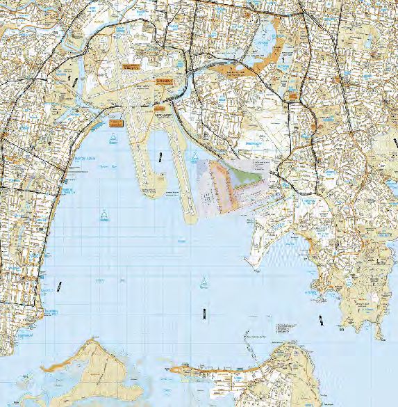
Port Botany Expansion
Impact on Airservices
Radar and Navigation Systems
at Sydney Airport
Issue No: 1.0
Issue Date: 11/07/2002
Prepared by: M.Wilson, G.Vaile, L.Nguyen (Radar)
Mario Perin (Navigation)
Infrastructure Support Services
Airservices Australia ABN 59 698 720 886
GPO Box 367 Telephone (02)6268 5544
Canberra ACT 2601 Facsimile (02) 6268 5533
© Airservices Australia. All rights reserved.
This document and the information contained herein is the property of Airservices Australia. No
part of this work may be reproduced or copied in any form or by any means (graphic, electronic
or mechanical, including photocopying, recording, taping or information retrieval system) or
otherwise disclosed to any party outside Airservices without the prior consent of the Manager,
Communications Services, ISS, Airservices Australia.Port Botany Expansion Impact on Airservices Radar and Navigation Systems at Sydney Airport
Issue No. 1.0 Issue Date: 11/07/2002
This page is intentionally blank.
Infrastructure Support Services Page 2 of 68
© Airservices AustraliaPort Botany Expansion Impact on Airservices Radar and Navigation Systems at Sydney Airport
Issue No. 1.0 Issue Date: 11/07/2002
Table of Contents
1 Scope. . . . . . . . . . . . . . . . . . . . . . . . . . . . . . . . . . . . . . . . . . . . . . . . . . . . . . . . . . . . . . . . . . . . 5
2 Sydney Airport Radar Services . . . . . . . . . . . . . . . . . . . . . . . . . . . . . . . . . . . . . . . . . . . . . . . . 5
2.1 Surface Movement Radar. . . . . . . . . . . . . . . . . . . . . . . . . . . . . . . . . . . . . . . . . . . . . . . . . . 5
2.2 Terminal Approach Radar (PSR) . . . . . . . . . . . . . . . . . . . . . . . . . . . . . . . . . . . . . . . . . . . . 5
2.3 Terminal Approach Radar (SSR) . . . . . . . . . . . . . . . . . . . . . . . . . . . . . . . . . . . . . . . . . . . . 5
2.4 Route Surveillance Radar, Mount Boyce (SSR) . . . . . . . . . . . . . . . . . . . . . . . . . . . . . . . . 5
2.5 Precision Approach Runway Monitor (PARM) . . . . . . . . . . . . . . . . . . . . . . . . . . . . . . . . . . 6
3 Radar Coverage Calculations Assumptions . . . . . . . . . . . . . . . . . . . . . . . . . . . . . . . . . . . . . . 6
3.1 Line Of Site Obstruction . . . . . . . . . . . . . . . . . . . . . . . . . . . . . . . . . . . . . . . . . . . . . . . . . . . 6
3.2 Reflection . . . . . . . . . . . . . . . . . . . . . . . . . . . . . . . . . . . . . . . . . . . . . . . . . . . . . . . . . . . . . . 6
4 Sydney Airport Radar Coverage . . . . . . . . . . . . . . . . . . . . . . . . . . . . . . . . . . . . . . . . . . . . . . . 6
4.1 Surface Movement Radar. . . . . . . . . . . . . . . . . . . . . . . . . . . . . . . . . . . . . . . . . . . . . . . . . . 6
4.2 Terminal Approach Radar (Primary). . . . . . . . . . . . . . . . . . . . . . . . . . . . . . . . . . . . . . . . . . 8
4.3 Terminal Approach Radar (Secondary) . . . . . . . . . . . . . . . . . . . . . . . . . . . . . . . . . . . . . . 15
4.4 Route Surveillance Radar (Secondary) Mount Boyce . . . . . . . . . . . . . . . . . . . . . . . . . . . 19
4.5 Precision Approach Runway Monitor (Secondary) . . . . . . . . . . . . . . . . . . . . . . . . . . . . . . 21
5 Sydney Airport Navigation Services . . . . . . . . . . . . . . . . . . . . . . . . . . . . . . . . . . . . . . . . . . . 26
5.1 Introduction to ILS . . . . . . . . . . . . . . . . . . . . . . . . . . . . . . . . . . . . . . . . . . . . . . . . . . . . . . 26
5.2 ILS Approach Procedure . . . . . . . . . . . . . . . . . . . . . . . . . . . . . . . . . . . . . . . . . . . . . . . . . 26
5.3 ILS Modelling of Port Botany Development . . . . . . . . . . . . . . . . . . . . . . . . . . . . . . . . . . . 28
5.4 Runway 16L Localizer . . . . . . . . . . . . . . . . . . . . . . . . . . . . . . . . . . . . . . . . . . . . . . . . . . . 28
5.5 Runway 34R Localizer . . . . . . . . . . . . . . . . . . . . . . . . . . . . . . . . . . . . . . . . . . . . . . . . . . . 30
5.6 Runway 34R Glide Path . . . . . . . . . . . . . . . . . . . . . . . . . . . . . . . . . . . . . . . . . . . . . . . . . . 31
5.7 Future Technologies . . . . . . . . . . . . . . . . . . . . . . . . . . . . . . . . . . . . . . . . . . . . . . . . . . . . . 31
6 Conclusion . . . . . . . . . . . . . . . . . . . . . . . . . . . . . . . . . . . . . . . . . . . . . . . . . . . . . . . . . . . . . . . 32
6.1 Sydney Airport Terminal Approach Radar (Primary) . . . . . . . . . . . . . . . . . . . . . . . . . . . . 32
6.2 Sydney Airport Terminal Approach Radar (Secondary) . . . . . . . . . . . . . . . . . . . . . . . . . . 32
6.3 Mount Boyce Route Surveillance Radar (Secondary) . . . . . . . . . . . . . . . . . . . . . . . . . . . 32
6.4 Sydney Airport Precision Approach Runway Monitor (Secondary) . . . . . . . . . . . . . . . . . 32
6.5 Sydney 16L Localizer . . . . . . . . . . . . . . . . . . . . . . . . . . . . . . . . . . . . . . . . . . . . . . . . . . . . 32
6.6 Sydney 34R Localizer. . . . . . . . . . . . . . . . . . . . . . . . . . . . . . . . . . . . . . . . . . . . . . . . . . . . 32
6.7 Sydney 34R Glide Path . . . . . . . . . . . . . . . . . . . . . . . . . . . . . . . . . . . . . . . . . . . . . . . . . . 33
6.8 Summary . . . . . . . . . . . . . . . . . . . . . . . . . . . . . . . . . . . . . . . . . . . . . . . . . . . . . . . . . . . . . 33
7 Definitions . . . . . . . . . . . . . . . . . . . . . . . . . . . . . . . . . . . . . . . . . . . . . . . . . . . . . . . . . . . . . . . 34
Annex A Radar Coverage Effects . . . . . . . . . . . . . . . . . . . . . . . . . . . . . . . . . . . . . . . . . . . . . . 37
1 Annex Scope . . . . . . . . . . . . . . . . . . . . . . . . . . . . . . . . . . . . . . . . . . . . . . . . . . . . . . . . . . . . . 37
2 Terminal Approach Radar (Primary) . . . . . . . . . . . . . . . . . . . . . . . . . . . . . . . . . . . . . . . . . . . 37
3 Terminal Approach Radar (Secondary) . . . . . . . . . . . . . . . . . . . . . . . . . . . . . . . . . . . . . . . . . 43
4 Precision Approach Runway Monitor (PARM). . . . . . . . . . . . . . . . . . . . . . . . . . . . . . . . . . . . 49
Annex B ILS Modelling Results . . . . . . . . . . . . . . . . . . . . . . . . . . . . . . . . . . . . . . . . . . . . . . . . 55
1 Sydney Runway 16L Localizer . . . . . . . . . . . . . . . . . . . . . . . . . . . . . . . . . . . . . . . . . . . . . . . 55
2 Sydney Runway 34R Localizer . . . . . . . . . . . . . . . . . . . . . . . . . . . . . . . . . . . . . . . . . . . . . . . 59
3 Sydney Runway 34R Glide Path . . . . . . . . . . . . . . . . . . . . . . . . . . . . . . . . . . . . . . . . . . . . . . 64
4 Localizer Antenna Systems . . . . . . . . . . . . . . . . . . . . . . . . . . . . . . . . . . . . . . . . . . . . . . . . . . 68
Infrastructure Support Services Page 3 of 68
© Airservices AustraliaPort Botany Expansion Impact on Airservices Radar and Navigation Systems at Sydney Airport
Issue No. 1.0 Issue Date: 11/07/2002
This page is intentionally blank
Infrastructure Support Services Page 4 of 68
© Airservices AustraliaPort Botany Expansion Impact on Airservices Radar and Navigation Systems at Sydney Airport
Issue No. 1.0 Issue Date: 11/07/2002
1 Scope
This report will discuss the impact of the proposed redevelopment on the accuracy and performance of
the various Radars and Navigation Systems providing services to Sydney Airport and if required, pro-
pose a strategy to mitigate any deleterious effects.
2 Sydney Airport Radar Services
The existing Radar services at Sydney Airport are:
2.1 Surface Movement Radar
Operating Range 5 Nautical Miles
Operating Frequency 9410 MHz
PRF approx. 4000 Hz
Critical Areas Thresholds and airport movement areas, see Figure 1
Main Tasks: - - Airport surface surveillance
- Correlation of airborne targets over the thresholds
2.2 Terminal Approach Radar (PSR)
Operating Range 40 Nautical Miles
Operating Frequencies 2770 and 2850 MHz
PRF 1000 Hz
Critical Areas 20 nm around Sydney Airport
Coverage See Figure 2
Main Tasks: - Intruder detection within 30nm of Sydney Airport
- Tracking of non-transponder equipped aircraft
2.3 Terminal Approach Radar (SSR)
Operating Range 255 Nautical Miles
Operating Frequencies 1030 and 1090 MHz
PRF 333 Hz
Critical Areas 20 nm around Sydney Airport
Coverage See Figure 7
Main Tasks: - Approach control within 40nm Sydney Airport
- Intruder detection within 30nm of Sydney Airport
- Tracking of transponder equipped aircraft along Eastern Seaboard
2.4 Route Surveillance Radar, Mount Boyce (SSR)
Operating Range 255 Nautical Miles
Operating Frequencies 1030 and 1090 MHz
PRF 333 Hz
Critical Areas 40 nm around Sydney Airport
Coverage See Figure 10
Main Tasks: - Control within 40 nm of Sydney Airport
- Tracking of transponder equipped aircraft along Eastern Seaboard
Infrastructure Support Services Page 5 of 68
© Airservices AustraliaPort Botany Expansion Impact on Airservices Radar and Navigation Systems at Sydney Airport
Issue No. 1.0 Issue Date: 11/07/2002
2.5 Precision Approach Runway Monitor (PARM)
Operating Range 32 Nautical Miles
Operating Frequencies 1030 and 1090 MHZ
PRF Variable
Critical Areas and Coverage see Figure 12
Main Tasks: - Precision Radar Approach control to the parallel runways
- Approach control within 30 nm of Sydney Airport.
3 Radar Coverage Calculations Assumptions
3.1 Line Of Site Obstruction
For calculations involving the radar line of site coverage, the height used in the calculations is taken
as the height of the top of the crane top (50 metres), as this is the worst case. The cranes occupy all
positions along the wharf front at some time.
3.2 Reflection
For calculations involving reflection of radar targets, the height used in the calculations is taken as
the height of the vessel container stack, or container stack on the ground. The crane contributes
little to the reflection environment.
4 Sydney Airport Radar Coverage
4.1 Surface Movement Radar
4.1.1 Surface Movement Radar Coverage
The Surface Movement Radar coverage is limited to the airport movement area, the area inside
the yellow line in Figure 1. It is sited on the Control Tower (TWR).
4.1.2 Surface Movement Radar Accuracy
Azimuth 4.0 Metres
Range 4.0 Metres
4.1.3 Expected Impact of Development
1) Minimal adverse affects, as the development is outside the coverage area.
2) Primary reflections will cause no problems.
3) Provided the berthing ships do not transit the approach path for 34R the threshold
detection will be unaffected.
4.1.4 Mitigation Strategy
None required, provided 3) above is adhered to.
Infrastructure Support Services Page 6 of 68
© Airservices AustraliaPort Botany Expansion Impact on Airservices Radar and Navigation Systems at Sydney Airport
Issue No. 1.0 Issue Date: 11/07/2002
Figure 1 SMR Coverage
Infrastructure Support Services Page 7 of 68
© Airservices AustraliaPort Botany Expansion Impact on Airservices Radar and Navigation Systems at Sydney Airport
Issue No. 1.0 Issue Date: 11/07/2002
4.2 Terminal Approach Radar (Primary)
4.2.1 TAR Primary Radar Coverage
This radar sensor is located on the airport, near the junction of taxiways “C” and “B10”, see
Figure 3 and is co-mounted with the TAR Secondary (Section 4.3 below). Data from the two
sensors are processed in the same Track Processor. Where the tracks are combined tracks,
(P+S) the position information from the most accurate sensor is used.
The coverage radius is 50 nautical miles from the TAR at position:
S33o 56’ 59.70” E151o 10’ 52.65” WGS 56.9m AHD 34.5m
The guaranteed coverage is 40 nautical miles.
The antenna is set with the main low beam at 3o above the horizon, see Figure 4.
4.2.2 TAR Primary Radar Accuracy
Azimuth ±0.15º RMS (primary only target)
Range ±0.03 nm RMS (primary only target)
Figure 2 TAR Vertical Coverage Envelope
Feet
50,000
40,000 1.5
30,000
1.0
20,000
0.5
10,000
Degrees
0 0
-10,000
0 10 20 30 40 50 60
70
-0.5
80 90
100 110
120
130
Nautical Miles 140
150
160 -1.0
170
180
4/3 Earth Chart 250 nm 190
200
210
220
230
240
Primary Radar Coverage Envelope
Infrastructure Support Services Page 8 of 68
© Airservices AustraliaPort Botany Expansion Impact on Airservices Radar and Navigation Systems at Sydney Airport
Issue No. 1.0 Issue Date: 11/07/2002
Figure 3 TAR Siting Restrictions
Infrastructure Support Services Page 9 of 68
© Airservices AustraliaPort Botany Expansion Impact on Airservices Radar and Navigation Systems at Sydney Airport
Issue No. 1.0 Issue Date: 11/07/2002
4.2.3 Expected Impact of Development
1) Reduction in Primary coverage at low altitudes in the direction of development, Figure 9,
between T1 and T2. The low level cutoff will be about 600’ at 10 nm from the radar, due to
masking by the new structures and vessels. Currently the coverage is to 100’ at this range.
See Figure 17 to Figure 19 and Figure 21. Vessels in transit to the dock along the normal
navigation leads show only minor disturbances to the primary vertical radiation pattern,
see Figure 20 and Figure 22.
Figure 21 shows that the performance of the second primary transmitter frequency is
substantially the same as that used for calculation of the other primary vertical patterns.
Due to lack of consistent detection this may cause some tracking problems with aircraft
below 600 feet AMSL in the coastal aircraft lane.
2) Large moving primary targets, typically any large maritime vessel, see Figure 6, within 10
to 15 nm that is illuminated by the radar may cause “ring around” due to side lobe
detection, see the horizontal radiation pattern in Figure 5. This can result in suppression of
real targets at the same range, and generation of “false” targets at all azimuths. The radar
siting and height, limit this affect to vessels in Botany Bay or in transit through the Heads.
The sidelobes of the antenna, see Figure 5, detect the vessel due to the large reflecting
area and the short range, these returns are not coherent with the energy received by the
antenna main beam causing a pseudo moving target to be generated. The primary
processor (TVD900), will suppress most of these false targets by increasing the detection
thresholds, but:
a) A percentage of the false targets will be displayed adding to the clutter near the
airport.
b) The detection sensitivity under the “ring around” will be reduced.
c) Primary azimuth disturbances may occur in the “ring around”, due to plot width
modulation by false targets.
The largest target expected represents a Cross Sectional Area, (CSA) of 40-60 square
metres in its best aspect and typically a CSA of 10-15 square metres in its worst aspect,
the smallest targets expected are Ultralight aircraft or Robinson R22 helicopters, these
have a CSA of 0.2 square metres.The maritime vessels expected in Botany Bay, see
Figure 6, can have areas of between 3200 square metres and 9900 square metres and
although not at optimum angles, probably have a reflection rate of more than 10% making
them 6-10 times the size of the largest “normal” targets.
3) Reflection of Kurnell coast will reduce sensitivity over the La Perouse Peninsula and in the
area bounded by T1 and T2 of Figure 9.
The large size of the vessels allows for reflection of the primary main beam from any
vessels berthed at the dock or in transit to the dock. Causing detection of targets along the
line of the reflection Figure 9, between TR1 and TR2. The “reflected path” will be via the
water increasing the attenuation, but large targets, (other maritime vessels and the
coastline), will be detected and superimposed over the real targets. The TVD900 will
suppress most of these effects, but:
a) There will be a reduction in detection sensitivity where these super impositions
occur.
b) There will be an increase in clutter, angels and short lived false targets.
The beam width of the antenna is 1.1º at the 3dB points, at the range of the docked
vessels, say 3km this represents 55 metres wide, as the vessels are 250 metres plus in
length, the whole of the beam is reflected in the side of the vessel and/or the container
stack.
Infrastructure Support Services Page 10 of 68
© Airservices AustraliaPort Botany Expansion Impact on Airservices Radar and Navigation Systems at Sydney Airport
Issue No. 1.0 Issue Date: 11/07/2002
4.2.4 Mitigation Strategy: -
The TAR antenna has been set with the main beam at +3.0º reference the horizon, see
Figure 4. This setting is a compromise between the clutter levels, detectability over the
thresholds and long range performance. Increasing the radiation angle to reduce
reflections will result in a reduction in performance over the thresholds and at long range
and is therefore not recommended. This setting can not be altered without a complete
flight test of the sensor.
1) No solution available. The reduction in primary coverage is entirely due to masking, the
only remedy is to increase the height of the radar, or relocate the radar to a more benign
position.
2) No solution available. Blanking and non-initialisation areas can be used to limit the
initiation of false tracks, but they do not discriminate between wanted and unwanted
targets. There is only 7 of each type of zone available, most of which are already in use to
suppress false targets generated by road traffic in the Sydney Basin.
a) No method exists to discriminate between the targets detected by the main lobe and
those detected by the sidelobes. The TVD900 will automatically increase the
thresholds to minimise the false tracks and clutter.
b) The desensitisation is a result of the automatic increase in the thresholds due to the
increased clutter levels.
c) No method exists to discriminate between the false targets and the real targets.
3) No solution available.
a) The reflections increase the automatic threshold levels decreasing the sensitivity.
b) Clutter and angel activity increase as a result of the non-coherent replies, the
automatic thresholding will eliminate most of this activity, but at the cost of detection
sensitivity.
4.2.4.1 Summary
Any performance adjustment will be an operational compromise between:
a) Increased false primary tracks and track seduction to clutter
b) Use of blanking areas to suppress all primary tracks
4.2.4.2 Technology Upgrade
The current primary processing equipment at the Sydney TAR is relatively old
(technologically speaking) and is a candidate for upgrading to later model processing.
Preliminary discussions with potential suppliers have occurred, but no time frame has
been discussed or proposed. The updated processing system generally improves the
performance under adverse conditions as those described above.
Infrastructure Support Services Page 11 of 68
© Airservices AustraliaPort Botany Expansion Impact on Airservices Radar and Navigation Systems at Sydney Airport
Issue No. 1.0 Issue Date: 11/07/2002
Figure 4 TAR Vertical Radiation Pattern (Primary)
Main Beam
Horizon
Infrastructure Support Services Page 12 of 68
© Airservices AustraliaPort Botany Expansion Impact on Airservices Radar and Navigation Systems at Sydney Airport
Issue No. 1.0 Issue Date: 11/07/2002
Figure 5 Tar Horizontal Radiation Pattern (Primary)
Back Lobes
Side Lobes
Main Lobe
Infrastructure Support Services Page 13 of 68
© Airservices AustraliaPort Botany Expansion Impact on Airservices Radar and Navigation Systems at Sydney Airport
Issue No. 1.0 Issue Date: 11/07/2002
Figure 6 Vessels expected in Botany Bay
16-32 metres
200-300
metres
Reflector Size:-
1500 TEU 200 x 16 = 3200 Metres
3000 TEU 260 x 23 = 5980 Metres
4500 TEU 300 x 27 = 8100 Metres
6000 TEU 320 x 31 = 9920 Metres
Oil Tanker 260 x 10 = 2600 Metres
8-16 metres
200-300
metres
Infrastructure Support Services Page 14 of 68
© Airservices AustraliaPort Botany Expansion Impact on Airservices Radar and Navigation Systems at Sydney Airport
Issue No. 1.0 Issue Date: 11/07/2002
4.3 Terminal Approach Radar (Secondary)
4.3.1 Terminal Approach Radar Coverage
This sensor is located on the airport, near the junction of taxiways “C” and “B10”, see Figure 3. It
is co-mounted with the TAR Primary (Section 4.2 above). Data from the two sensors are
processed in the same Track Processor. Where the tracks are combined tracks (P+S), the
position information from the most accurate sensor is used.
The coverage radius is 255 nautical miles from the TAR at position: -
S33o 56’ 59. 70” E151o 10’ 52.65” W56.9M AHD34.5M
The guaranteed coverage is 255 nautical miles.
The main beam of the SSR is set at +10º reference the horizon. See Figure 8
Figure 7 TAR SSR Vertical Coverage Envelope
Feet
50,000
40,000 1.5
30,000
1.0
20,000
0.5
10,000
Degrees
0 0
-10,000
0 10 20 30 40 50 60 -0.5
70 80 90
100 110
120
130
Nautical Miles 140
150 -1.0
160
170
180
4/3 Earth Chart 250 nm 190
200
210
220
230
240
Secondary Radar Coverage Envelope
Infrastructure Support Services Page 15 of 68
© Airservices AustraliaPort Botany Expansion Impact on Airservices Radar and Navigation Systems at Sydney Airport
Issue No. 1.0 Issue Date: 11/07/2002
Figure 8 SSR Vertical Radiation Pattern
Mechanical
Scale
Radiation
Angleangle
Horizon
Infrastructure Support Services Page 16 of 68
© Airservices AustraliaPort Botany Expansion Impact on Airservices Radar and Navigation Systems at Sydney Airport
Issue No. 1.0 Issue Date: 11/07/2002
Figure 9 TAR Reflection Geometry (SSR)
TR3
TR4
TAR
T1
TR1
TR2
Sh
ip
sP
at
h
Maps Reproduced Courtesy of AUSWAY
T2
4.3.2 Terminal Approach Radar Accuracy (Secondary)
1) Azimuth ±0.05º RMS
2) Range ±0.03 nm RMS
4.3.3 Expected Impact of Development
1) Reduction in secondary coverage at low altitudes in the direction of the development,
between Figure 9, T1 and T2. Coverage below 600’ at 10 nm from the radar will be patchy
due to diffraction over the Port. Currently the coverage is to 100’ at this range. See Figure
23 to Figure 27.
Due to lack of consistent detection this may cause some tracking problems with aircraft
below 600 feet AMSL in the coastal aircraft lane.
Infrastructure Support Services Page 17 of 68
© Airservices AustraliaPort Botany Expansion Impact on Airservices Radar and Navigation Systems at Sydney Airport
Issue No. 1.0 Issue Date: 11/07/2002
Vessels in transit to the dock along the normal navigation leads show only minor
disturbances to the secondary vertical radiation pattern, see Figure 26 and Figure 28.
2) Increased reflections between Figure 9, T1 and T2 at all ranges, caused by aircraft in the
southern sector, between Figure 9, TR1 and TR2, and north eastern sector Figure 9, TR3
and TR4.
The track processor uses three criteria for discriminating between real and reflecting
targets. They are: -
a) Targets must be the same discrete reply code
b) the reflected target will have a longer range than the real target.
c) The reflected target should have a lower received field strength than the real target.
This level is adjustable from “zero” difference to any negative level desired.
The large size of the vessels will allow the reflection of the SSR main beam and
interrogation of aircraft that are off azimuth. The reflection path will be via the water for at
least one path, so the path loss will be increased over the direct path, this should enable
the tracking processor to discriminate between real and “reflected” tracks. Targets in this
group should meet all three criteria.
When the reflection angle is small it is possible to interrogate via the reflector and reply
direct to the radar antenna, thus making the reflection identification process more difficult.
Targets in this group should meet two of the criteria, ( a) and ( b).
The beam width of the antenna is 2.2º at the 3dB points, at the range of the docked
vessels, say 3km this represents 110 metres wide, as the vessels are 250 metres plus in
length the whole of the beam is reflected in the side of the vessel and/or the container
stack.
3) All Aircraft on approach to runways 34L and 34R will transit through the new reflection
zone. See Figure 9.
4.3.4 Mitigation Strategy
The TAR/SSR antenna has been set with the main beam at +10.0o reference the horizon, see
Figure 8, this antenna is a sharp cutoff array minimising the radiation at angles below the peak of
the beam. The setting is a compromise between the level of reflections and long range
detectability. Increasing the radiation angle to further reduce reflections will result in a reduction
in performance at long range and is therefore not recommended. This setting can not be altered
without a complete flight test of the sensor.
1) No solution available. The coverage reduction is caused by masking, the only remedy is to
increase the height of the radar, or relocate the radar to a more benign position.
2) There are several improvements that can be made to improve the reflection performance.
They are:
a) Retuning of the Track Processors to ensure optimum reflection processing.
b) Adjustment of SSR Interrogators to reduce interrogate power in the sectors
concerned.
c) Adjustment of SSR Receivers to reduce receive sensitivity in the sectors
concerned.
Items ( b) and ( c) reduce the long range performance of the sensor, a balance will have to
be met in making these adjustments.
Note: There are no secondary non initialisation or blanking zones used by the SSR
processing. Replies originate from a transponder and any valid replies MUST create a
track. The later processing must differentiate between real and reflected tracks.
3) Any reflections in this zone MUST be infrequent as they will cause problems with flight
plan processing in the display system, for departing aircraft.
Infrastructure Support Services Page 18 of 68
© Airservices AustraliaPort Botany Expansion Impact on Airservices Radar and Navigation Systems at Sydney Airport
Issue No. 1.0 Issue Date: 11/07/2002
4.4 Route Surveillance Radar (Secondary) Mount Boyce
4.4.1 Route Surveillance Radar Coverage
The coverage radius is 255 nautical miles from the RSR at position:
S33o 36’ 47. 61” E150o 16’ 10.15” W1144.0M AHD1118.6M
(this position is approximately 50 nautical miles bearing 293º from Sydney Airport, near
Blackheath in the Blue Mountains)
The guaranteed coverage is 255 nautical miles and to runway level at Sydney Airport.
The antenna main beam is set to +9º. See Figure 8
Figure 10 RSR SSR Vertical Coverage Envelope
Feet
50,000
40,000 1.5
30,000
1.0
20,000
0.5
10,000
Degrees
0 0
-10,000
0 10 20 30 40 50 60 -0.5
70 80 90
100 110
120
130
Nautical Miles 140
150 -1.0
160
170
180
4/3 Earth Chart 250 nm 190
200
210
220
230
240
Secondary Radar Coverage Envelope
Infrastructure Support Services Page 19 of 68
© Airservices AustraliaPort Botany Expansion Impact on Airservices Radar and Navigation Systems at Sydney Airport
Issue No. 1.0 Issue Date: 11/07/2002
Figure 11 Mt.Boyce Reflection Geometry (SSR)
Mt.Boyce RSR TAR
50NMI @ 293º
MB1
MBR1
MBR2 Sh
ip MB2
s Pa
t h
Maps Reproduced Courtesy of AUSWAY
4.4.2 Route Surveillance Radar Accuracy
Azimuth ±0.05º RMS
Range ±0.03 nm RMS
4.4.3 Expected Impact of Development
1) Increased reflections between, Figure 11, MB1 and MB2, from aircraft in the southern
sector between, Figure 11, MBR1 and MBR2, at all ranges exceeding 50 nm.
The reflection path will be via the water and the increased path loss via the reflector should
be significant.
The beam width of the antenna is 2.2o at the 3dB points, at the range of the docked
vessels, say 100km this represents 1.8 km wide, as the vessels are 250 metres in length
Infrastructure Support Services Page 20 of 68
© Airservices AustraliaPort Botany Expansion Impact on Airservices Radar and Navigation Systems at Sydney Airport
Issue No. 1.0 Issue Date: 11/07/2002
only part of the beam is reflected in the side of the vessel and/or the container stack. When
4 vessels are berthed a larger reflecting surface will be present.
2) All Aircraft on approach to runways 34L and 34R will transit through the new reflection
zone. See Figure 11, between MBR1 and MBR2.
4.4.4 Mitigation Strategy:
The RSR/SSR antenna has been set with the main beam at +9.0o reference the horizon, see
Figure 8. This antenna is a sharp cutoff array. The setting is a compromise between the level of
reflections and long range detectability. Increasing the radiation angle to further reduce
reflections will result in a reduction in performance at long range and is therefore not
recommended. This setting can not be altered without a complete flight test of the sensor.
1) There are several improvements that can be made to improve the reflection performance.
They are:
a) Retuning of the Track Processors to ensure optimum reflection processing.
b) Adjustment of SSR Interrogators to reduce interrogate power in the sectors
concerned.
c) Adjustment of SSR Receivers to reduce receive sensitivity in the sectors
concerned.
Items ( b) and ( c) reduce the long range performance of the sensor, a balance will have to
be met in making these adjustments.
Note: There are no secondary non initialisation or blanking zones used by the SSR
processing. Replies originate from a transponder and any valid replies MUST create a
track. The later processing must differentiate between real and reflected tracks.
2) Any reflections in this zone MUST be infrequent as they will cause problems with flight
plan processing in the display system, for departing aircraft.
4.5 Precision Approach Runway Monitor (Secondary)
4.5.1 Precision Approach Runway Monitor Coverage
The coverage radius is 32 nautical miles from the Radar at position:
S33o 56’ 37.71” E151o 10’ 57.34” W55.0M AHD32.6M
The PARM is sited on the airport, adjacent the Control Tower Complex.
The guaranteed coverage is 32 nautical miles.
In Figure 12, the area inside the 32 nm circle is used for Multi Radar Tracking (MRT) in the
Sydney TMA display. The area in blue is the zone in use for simultaneous approaches, high
update rate zone.
4.5.2 Precision Approach Runway Monitor Accuracy
Azimuth Better than 1 milliradian, (0.06º)
Range ±0.01 nm RMS
Infrastructure Support Services Page 21 of 68
© Airservices AustraliaPort Botany Expansion Impact on Airservices Radar and Navigation Systems at Sydney Airport
Issue No. 1.0 Issue Date: 11/07/2002
Figure 12 PARM Coverage Area.
32NMI
e
t e Zon
a
h Upd
Hig
Low Update Zone
3NMI
Low Update Zone
e
t e Zon
a
h Upd
Hig
4.5.3 PARM Licensing Requirements: -
Extract from the CASA Manual of Operational Standards, Part 3. Aerodromes;
4. Parallel Runway Standards
Approved by Assistant Director, Aviation Safety Standards Version 3.3: March 2002
4.3 Instrument Departures from Parallel Runways
4.3.1 Parallel runways may be used for independent departures provided:
a. The runway centre lines are separated by at least 760 m.
b. The departure tracks diverge by at least 15º immediately after take-off.
c. Suitable radar capable of identification of the aircraft within 1.0 nm from the end of
the runway is available.
d. ATS operational procedures ensure that the required track divergence is achieved.
4.4 Instrument Arrivals to Parallel Runways
4.4.1 Use for Independent and Dependent Arrivals
4.4.1.1 Parallel runways may be used for independent and dependent arrivals
subject to the following described in ensuing paragraphs:
* Independent Parallel Approaches
* Dependent Parallel Approaches.
Infrastructure Support Services Page 22 of 68
© Airservices AustraliaPort Botany Expansion Impact on Airservices Radar and Navigation Systems at Sydney Airport
Issue No. 1.0 Issue Date: 11/07/2002
4.4.2 Independent Parallel Approaches
4.4.2.1 Independent parallel approaches may be conducted to parallel runways
with centre-lines separated by at least 1035 m, provided that:
a. For runways separated by greater than 1525 m, suitable surveillance radar
with a minimum azimuth accuracy of 0.3º (one sigma) and update period of 5
seconds or less is available.
b. For runways separated by less than 1525 m, suitable surveillance radar with a
minimum azimuth accuracy of 0.06º (one sigma) and update period of 2.5
seconds or less and a high resolution display providing position prediction
and deviation alert, is available.
c. Instrument landing system (ILS) approaches are being conducted on both
runways.
d. The aircraft are making straight-in approaches.
e. Aircraft are advised of the runway identification and ILS localizer frequency.
Note: Para 4.4.2.1 b applies as the runway separation is less than 1525 metres.
Figure 13 PARM Reflection Geometry.
PR3
PR4
PARM
PR1
PR2 P1
Sh
ip
s Pa
t h
Maps Reproduced Courtesy of AUSWAY
P2
Infrastructure Support Services Page 23 of 68
© Airservices AustraliaPort Botany Expansion Impact on Airservices Radar and Navigation Systems at Sydney Airport
Issue No. 1.0 Issue Date: 11/07/2002
Figure 14 PARM No Transgression Zones
10 nm
2000’
4.5.4 Expected Impact of Development.
1) Reduction in PARM accuracy for precision approaches to runways 34L and 34R.
Particularly affecting the “No Transgression Zone”, Figure 14. The PARM accuracy could
be reduced to the point where its performance is outside the requirement for simultaneous
approaches to be conducted.
2) Increased reflections between Figure 13, P1 and P2 at all ranges, caused by aircraft in
the southern sector between Figure 13, PR1 and PR2, and north eastern sector Figure 13,
PR3 and PR4.
The track processor uses three criteria for discriminating between real and reflecting
targets. They are:-
a) Targets must be the same discrete reply code
b) The reflected target will have a longer range than the real target.
c) The reflected target should have a lower received field strength than the real target.
This level is adjustable from “zero” difference to any negative level desired.
Infrastructure Support Services Page 24 of 68
© Airservices AustraliaPort Botany Expansion Impact on Airservices Radar and Navigation Systems at Sydney Airport
Issue No. 1.0 Issue Date: 11/07/2002
The large size of the vessels will allow the reflection of the SSR main beam and
interrogation of aircraft that are off azimuth. The reflection path will be via the water for at
least one path, so the path loss will be increased over the direct path, this should enable
the tracking processor to discriminate between real and “reflected” tracks. Targets in this
group should meet all three criteria.
When the reflection angle is small, it is possible to interrogate via the reflector and reply
direct to the radar antenna, thus making the reflection identification process more difficult.
Targets in this group should meet two of the criteria, ( a) and ( b).
3) All Aircraft on approach to runways 34L and 34R will transit through the new reflection
zone. See Figure 13
4.5.5 Mitigation Strategy
1) There are several actions that can be made to resolve PARM accuracy problem. They
are:
a) Do not use Independant parallel approaches. This will restrict the capacity of
Sydney Airport.
b) The azimuth accuracy reduction is caused by multiple horizontal paths to the target.
The impact of these multiple paths can be minimised by relocating the radar to a
more benign position. This may involve a PARM at each end of the North /South
Runways.
Note: The above statement does not imply availability of alternative sites for the PARM.
2) There are several improvements that can be made to improve the reflection performance.
They are:-
a) Retuning of the Track Processors to ensure optimum reflection processing.
b) Adjustment of SSR Interrogators to reduce interrogate power in the sectors
concerned.
c) Adjustment of SSR Receivers to reduce receive sensitivity in the sectors
concerned.
3) Any reflections in this zone MUST be infrequent as they will cause problems with
simultaneous approaches and flight plan processing in the display system, for departing
aircraft.
Note: The reduction in accuracy is due to the multiple horizontal paths to the target. The
analysis tools supplied by the sensor manufacturer give a go/nogo result. The
manufacturer has advised Airservices that these tools are only a reliable guide. Later
modelling software now available can predict the sensor performance reliably. This
software is available to manufacturer, and they are willing to perform the analysis, (cost
approx $US 65,000).
Note: If the performance prediction was favourable, the sensor would need to be flight
tested to confirm the accuracy with the development in place.
Infrastructure Support Services Page 25 of 68
© Airservices AustraliaPort Botany Expansion Impact on Airservices Radar and Navigation Systems at Sydney Airport
Issue No. 1.0 Issue Date: 11/07/2002
5 Sydney Airport Navigation Services
Navigation systems are provided for the safe and efficient operation of aircraft in terminal areas,
including approach and landing at airports. To ensure their proper operation, most of these facilities
have associated restricted or clearance areas. Details of these can be found in Rules and Practices for
Aerodromes (RPA) Volume 1, Book 2, Chapter 20.
Components of Airservices Instrument Landing Systems at Sydney Airport that potentially could be
impacted upon by the expansion of Port Botany are:
• Runway 16L Localizer
• Runway 34R Localizer
• Runway 34R Glide Path
The normal site restrictions for these systems are shown in Figure 15.
5.1 Introduction to ILS
Instrument Landing Systems (ILS) is the international standard system for approach and landing
guidance. ILS was adopted by ICAO (International Civil Aviation Organisation) in 1947 and will be in
service until at least 2015. Because of the worldwide adoption of ICAO’s technical specifications,
any ILS equipped aircraft can expect to satisfactorily use the system at any airport.
An ILS normally comprises of a "Localizer" aligned with the runway centreline and providing azimuth
guidance, a "Glide Path" for elevation guidance, and either "Marker Beacons" or DME for providing
distance to touchdown information along the approach path.
The Localizer (LLZ), which provides lateral guidance, produces a course formed by the intersection
of two antenna radiation patterns. One pattern is modulated by 90Hz and the other by 150Hz. The
runway centreline is the vertical plane where the 90Hz and 150Hz modulation is equal.
The signal received by the airborne receiver produces a "fly right" indication for the pilot when the
aircraft is to the left of centreline in the predominately 90Hz region. Similarly a "fly left" indication will
be produced for the pilot on the opposite side of the centreline in the predominately 150Hz region.
The Glide Path (GP) produces two radiation patterns in the vertical plane which intercept at the
decent angle, namely the 3 degree glide slope. Below the glide slope angle, 150Hz predominates
giving a "fly up" indication. Above the glide slope angle a "fly down" indication will be produced by
the 90Hz predominance. The GP is sited about 300m behind the runway threshold to give a
threshold crossing height of between 15m and 18m.
All elements of the ILS are carefully monitored, and any malfunction causes a warning signal to alert
the ground controller. The ILS is automatically switched off if the system is not functioning correctly.
5.2 ILS Approach Procedure
An ILS procedure begins with the transition from enroute to final approach. The aircraft intercepts
the Localizer course in level flight at an altitude and distance (specified by the approach plate of the
pilot’s flight manual) that places the aircraft below the 3 degree glide slope. This allows the pilot to
become stabilised on the localizer before starting the descent. As the aircraft intercepts the glide
slope sector, the indicator starts to move towards the centre and the pilot then makes the necessary
power and trim adjustments to give a rate of descent consistent with the glide slope angle.
If the approach is being made to Category one weather minima (down to 200ft above the airport),
the pilot must have in view an element of the approach lights, runway lights or markings by the time
he reaches the minimum decent altitude. If he reaches this decision height and does not have
adequate visual reference, he must abort the approach and execute a missed approach procedure.
Infrastructure Support Services Page 26 of 68
© Airservices AustraliaPort Botany Expansion Impact on Airservices Radar and Navigation Systems at Sydney Airport
Issue No. 1.0 Issue Date: 11/07/2002
Figure 15 ILS Site Restrictions
Infrastructure Support Services Page 27 of 68
© Airservices AustraliaPort Botany Expansion Impact on Airservices Radar and Navigation Systems at Sydney Airport
Issue No. 1.0 Issue Date: 11/07/2002
5.3 ILS Modelling of Port Botany Development
Analysis of the Port Botany development indicates that interference to the ILS will most likely be
caused by container ships, particularly while they are transitting to the dock.
The proposed new crane and dock area, because of its distance from the 16L/34R runway
centreline, and its substantially open lattice structure are considered unlikely to impact on the ILS.
Modelling of the Port Botany development therefore focused on the impact the various size
container ships will have on the ILS. Container ships were modelled in several. positions and
orientations with respect to the effected ILS components described earlier.
The classes of container ships that were considered, together with their dimensions are shown in
Figure 16.
Figure 16 Class of Container ships
Simplified Dimensions (metres)
Class of Ship (TEU)
X Y Z Y+Z W Water level to AHD
1500 200 7.5 8.0 15.5 25 +1.0m
3000 260 10.0 13.0 23.0 32 +1.0m
4500 300 12.0 15.5 27.5 37 +1.0m
6000 320 13.5 18.0 31.5 43 +1.0m
SIMPLIFIED PROFILE
0.1 X
DECK CONTAINERS (MAX)
Z
WATER HULL OF VESSEL Y
LEVEL
X W
Not to scale
Computer modelling was undertaken using the Localizer AXIS 110 and Glide Path AXIS 330
programs. AXIS uses the same formulae as the GEC-Marconi VLOC. The validity of VLOC has
been confirmed on United Kingdom Government Contracts and on work for the UK CAA.
Interference to either the Localizer or Glide Path course structure of about ± 10 PA or greater is
considered as unacceptable.
5.4 Runway 16L Localizer
The Sydney Runway 16L Localizer is located on the extended runway centreline, approx 250m
beyond the stop end of runway 16L.
The 16L Localizer co-ordinates are:
S33o 58’ 23.88” E151o 11’ 40.07” WGS 26.1 m AHD 3.7 m
Infrastructure Support Services Page 28 of 68
© Airservices AustraliaPort Botany Expansion Impact on Airservices Radar and Navigation Systems at Sydney Airport
Issue No. 1.0 Issue Date: 11/07/2002
Flight tests show that the Runway 16L Localizer course structure currently exhibits bends and
deviations of ± 2 PA as a result of existing structures and objects on the airport.
5.4.1 Modelling
The impact on the 16L Localizer was assessed by modelling the various classes of container
ships in the positions, and with orientations as shown in Table 5.1.
Table 5.1 Runway 16L Localizer
Distance offset from Distance forward Orientation of ship wrt to runway
Class of Ship
runway centreline of facility centreline *
1500 0o 5o 10o 20o 45o
400 m north
800 m north
3000 0o 5o 10o 20o 45o
500m east
1200 m north 4500 0o 5o 10o 20o 45o
1600 m north
6000 0o 5o 10o 20o 45o
* 0o indicates parallel to runway centreline
5.4.2 Results
The modelling results indicate that the TEU 1500 class of ship will have negligible impact on the
16L Localizer if they are maintained at least 500m east of the 16L/34R runway centreline.
For the TEU 3000 class of ship, the impact will be negligible if the ship is maintained at least
550m from the 16L/34R runway centreline.
For both the TEU 4500 and TEU 6000 classes of ships, an unacceptable level of interference will
occur to the 16L Localizer, when those ships are transitting or docked at the Port.
Annex B 1.1 to 1.6 show typical results from modelling the impact of the different class of ships
on the Sydney 16L Localizer.
5.4.3 Mitigation Strategy
Interference to the 16L Localizer from the TEU 4500 and TEU 6000 classes of ships can be
reduced to an acceptable level by upgrading the current Localizer antenna system to a higher
category, such as a 24 element antenna system. The current antenna system is a 12 element
antenna array and is capable of being upgraded to a 24 element array without replacing the
existing transmitter and building.
The cost of upgrading the existing 16L Localizer antenna, testing and re-commissioning is
estimated to be $600,000.
Annex B 4.1 shows the typical radiation pattern of a 12 element Localizer antenna array. Shown
in Annex B 4.2 is a the typical radiation pattern of a 24 element Localizer antenna. Note the
smaller beam width which reduces the amount of side radiation, and the therefore the
susceptibility of the Localizer to interference from lateral sources.
Annex B 1.7 to 1.8 show typical results for the interference caused by TEU 6000 class of ships
on the SY 16L Localizer, if upgraded to a 24 element array. The interference, while still
discernible, is reduced to an acceptable level of less than ± 10 PA.
Infrastructure Support Services Page 29 of 68
© Airservices AustraliaPort Botany Expansion Impact on Airservices Radar and Navigation Systems at Sydney Airport
Issue No. 1.0 Issue Date: 11/07/2002
5.5 Runway 34R Localizer
The Sydney Runway 34R Localizer is located on the extended runway centreline, approx 240m
beyond the stop end of runway 34R.
The 34R Localizer co-ordinates are:
S33o 56’ 51.04” E151o 11’ 15.97” WGS 27.1 m AHD 3.1 m
Flight tests show that the Runway 34R Localizer course structure currently exhibits bends and
deviations of ± 2 PA as a result of existing structures and objects on the airport.
5.5.1 Modelling
The impact on the 34R Localizer was assessed by modelling the various classes of container
ships in the positions and with orientations as shown in Table 5.2.
Table 5.2 Runway 34R Localizer
Distance offset from Orientation of ship wrt to runway
Distance of facility Class of Ship
Runway Centreline centreline *
1500 0o 5o 10o 20o 45o
1600 m south
500 m east
2000 m south 3000 0o 5o 10o 20o 45o
2400 m south
600 m east
2800 m south 4500 0o 5o 10o 20o 45o
3200 m south
6000 0o 5o 10o 20o 45o
* 0o indicates parallel to runway centreline
5.5.2 Results
Modelling results indicate that the TEU 1500 class of ships will have negligible impact on the 34R
Localizer, providing they are maintained at least 500m from the 16L/34R runway centreline.
However, for the TEU 3000, TEU 4500 and TEU 6000 classes of ships, an unacceptable level of
interference will occur to the 34R Localizer, when those ships are either transitting to, or docked
at the Port.
Annex B 2.1 to 2.8 show typical results of modelling the impact from the different class of ships
on the Sydney 34R Localizer.
5.5.3 Mitigation Strategy
The interference to 34R Localizer from the TEU 3000 class of ships can be reduced to an
acceptable level by upgrading the current Localizer antenna system to a higher category such as
a 24 element antenna system. The current 34R Localizer antenna system is a 12 element array
and is capable of being upgraded to a 24 element array without replacing the existing transmitter
and building.
For the TEU 4500 and TEU 6000 classes of ships, in addition to upgrading the existing 34R
Localizer antenna to a 24 element array, these ships would need to be maintained a distance
greater than 550m from the 16L/34R runway centreline, in order to reduce the level of
interference to an acceptable level.
The cost of upgrading the existing 34R Localizer antenna, testing and re-commissioning is
estimated to be $600,000.
Annex B 4.1 shows the typical radiation pattern of a 12 element Localizer antenna array. Shown
in Annex B 4.2 is a the typical radiation pattern of a 24 element Localizer antenna. Note the
smaller beam width which reduces the amount of side radiation, and the therefore the
susceptibility of the Localizer to interference from lateral sources.
Infrastructure Support Services Page 30 of 68
© Airservices AustraliaPort Botany Expansion Impact on Airservices Radar and Navigation Systems at Sydney Airport
Issue No. 1.0 Issue Date: 11/07/2002
5.6 Runway 34R Glide Path
The Sydney Runway 34R Glide Path is located on the western side of the 16L/34R runway
centreline, 152m from the centreline and backset 350m from the 34R runway threshold.
The 34R Glide Path co-ordinates are:
S33o 58’ 05.77” E151o 11’ 29.31” WGS 25.1 m AHD 2.7 m
The 34R Glide Path course structure currently exhibits bends and deviations of ± 4 PA as a result of
existing structures and objects in the airport environment.
5.6.1 Modelling
The impact on the 34R Glide Path was assessed by modelling the various classes of container
ships in the positions, and with orientations as shown in Table 5.3.
Table 5.3 Runway 34R Glide Path
Distance offset from Orientation of ship wrt to runway
Distance of facility Class of Ship
Runway Centreline centreline *
1500 0o 5o 10o 20o 45o
400 m south
800 m south
3000 0o 5o 10o 20o 45o
500 m east
1200 m south 4500 0o 5o 10o 20o 45o
1600 m south
6000 0o 5o 10o 20o 45o
* 0o indicates parallel to runway centreline
5.6.2 Results
Modelling results indicate that the TEU 1500 class of ship will have negligible impact on the 34R
Glide Path, provided they are maintained at least 400m east of the 16L/34R runway centreline.
For the TEU 3000, TEU 4500 and TEU 6000 classes of ships, these will have negligible impact
on the 34R Glide Path if they are maintained at least 500m east of the 16L/34R runway
centreline.
Annex B 3.1 to 3.8 show typical results of modelling the impact from the different class of ships
on the Sydney 34R Glide Path.
5.6.3 Mitigation Strategy
None are required if the TEU 1500 class of ships is maintained at greater than 400m east of the
16L/34 Runway centreline, and the TEU 3000, TEU 4500 and TEU 6000 are maintained at least
500m east of the runway centreline.
The above lateral separations from the 16L/34R runway centreline are required to be maintained
for at least 1000m south of the 34R Glide Path facility.
5.7 Future Technologies
Current forecasts indicate that ILS will be required at Sydney Airport until 2015, and possibly as late
as 2020. Satellite based landing systems are emerging as the replacement technology for ILS. An
alternative, but rarely used ground based landing system, is MLS (Microwave Landing System).
Both MLS and satellite based landing systems require significantly less site restrictions than does
ILS. In circumstances where these technologies are installed on Runway 16L and 34R, and the
existing ILS on these runways is decommissioned, it is not expected that the expansion of Port
Botany will have as significant an impact on the navigation systems at Sydney Airport.
Infrastructure Support Services Page 31 of 68
© Airservices AustraliaPort Botany Expansion Impact on Airservices Radar and Navigation Systems at Sydney Airport
Issue No. 1.0 Issue Date: 11/07/2002
6 Conclusion
6.1 Sydney Airport Terminal Approach Radar (Primary)
The main effect on the TAR Primary will be obstruction of low altitude targets along the azimuth of
the Port Botany Expansion. Currently, targets at sea level are visible to 20 nm. After the expansion,
targets will not be visible below 1200’ at 20 nm. Some target detection sensitivity reduction over the
La Perouse Peninsula because of primary reflection and increased false targets inside 10 nm due to
“ring around”.
6.2 Sydney Airport Terminal Approach Radar (Secondary)
Similarly the TAR Secondary will suffer obstruction of low altitude targets along the azimuth of the
Port Botany Expansion. Currently, targets at sea level are visible to 14 nm. After expansion, targets
will not be visible below 1200’ at 14 nm. There will be an increase in reflections due to the large flat
sides of the ships and containers. The reflection path will be via the surface of the water, increasing
the path attenuation and improving the possibility of detecting the reflecting signals and removing
them.
6.3 Mount Boyce Route Surveillance Radar (Secondary)
The Mount Boyce Secondary will suffer an increase in reflections due to the large flat sides of the
ships and containers. The reflection path will be via the surface of the water, increasing the path
attenuation and improving the possibility of detecting the reflecting signals and removing them.
6.4 Sydney Airport Precision Approach Runway Monitor (Secondary)
Based on the results of the initial analysis, the proposed developments are not within the normal
siting guidelines for PARM operation. Initial results indicate that the proposed structure could have a
major impact on PARM operations in terms of azimuth accuracy due to horizontal multipath
degradation.
PRM operation and PARM’s radar as a backup to Sydney TAR will be affected by the proposed
development. Further investigation is required to examine the impacts of such structures. Several
factors can influence the operation of the PARM and the construction, including proposed
development timing and operation of the port and required operation of the PARM. Since the
proposed container vessels are not static structures, the impact can be small or large depending on
time of usage for the PARM and the ships, and also the orientation of the vessels – either broadside
or head-on when viewed by the PARM.
6.5 Sydney 16L Localizer
Modelling indicates that the proposed expansion will significantly interfere with the operation of the
Sydney 16L Localizer. The interference can be mitigated by upgrading the existing 16L Localizer
antenna system to a 24 element array, estimated to cost $600,000. All classes of container ships will
also be required to be maintained at a distance greater than 500m east of the 16L/34R runway
centreline.
6.6 Sydney 34R Localizer
Modelling indicates the proposed expansion will significantly interfere with the operation of the
Sydney 34R Localizer. The interference can be mitigated by upgrading the existing 34R Localizer
antenna system to a 24 element array, estimated to cost $600,000. In addition, TEU 1500 and TEU
3000 classes of container ships will be required to be maintained at a distance greater than 500m
east of the 16L/34R runway centreline. TEU 4500 and TEU 6000 classes of ships will be required to
be maintained at a distance greater than 550m from the 16L/34R runway centreline.
Infrastructure Support Services Page 32 of 68
© Airservices AustraliaPort Botany Expansion Impact on Airservices Radar and Navigation Systems at Sydney Airport
Issue No. 1.0 Issue Date: 11/07/2002
6.7 Sydney 34R Glide Path
Modelling indicates the proposed expansion will not interfere with the operation of the Sydney 34R
Glide Path, providing all classes of container ships are maintained at a distance greater than 500m
east of the 16L/34R runway centreline, for a distance of 1000m south of the 34R Glide Path facility
(equivalent to 650m south of the 34R runway threshold).
6.8 Summary
The level of radar sensor performance degradation caused by the Port Botany Expansion is
manageable using system tuning and site operating condition adjustments that are available for the
various radar systems. The effects on the operational performance of the radar coverage will be
minor and the system safety will not be compromised.
The only exception to this is the Precision Approach Runway Monitor, the azimuth errors introduced
to the southern approach path will compromise the system safety margins. No remedy is available
at this time.
The PARM is scheduled for replacement around 2009, this is about the commissioning time of the
first berth in the Port Botany Expansion. There is no other type of sensor or alternative technology
currently approved by either the FAA or CASA that meets the licensing requirements for
independant parallel approaches at this time.
Both the 16L and 34R instrument landing systems will be required to be upgraded at a total cost of
$1.2 million. In addition the TEU 1500 and 3000 classes of ships will be required to me maintained
at more than 500m from the 16L/34R runway centreline, and TEU 4500 and TEU 6000 classes of
ships at greater than 550m from the runway centreline. The lateral separations will be required to be
maintained for 650m south of the 34R runway threshold.
Infrastructure Support Services Page 33 of 68
© Airservices AustraliaPort Botany Expansion Impact on Airservices Radar and Navigation Systems at Sydney Airport
Issue No. 1.0 Issue Date: 11/07/2002
7 Definitions
4/3 Earth Chart
A graphical representation of the earths surface with respect to the radio frequency
propagation path, RF travels in a curve with a radius of 4/3 that of the earth. The RF
path is drawn as a straight line so the earths surface is a curve falling away from the RF
path.
AEI
Airways Engineering Instruction, a document describing the standards, maintenance
procedures and operation of any navigational aid in use by Airservices Australia.
Angels
unwanted primary radar echoes that cannot be explained.
Blanking Zone
an area defined in the radar tracker in which all primary tracks are suppressed.
Boresight
The horizontal centre of the antenna interrogate pattern in space, 0º of the SUM
pattern.
CASA
Civil Aviation Safety Authority, the regulatory and licensing agency
Clutter
Unwanted primary radar targets from any source.
Combined Track
A track that contains both primary and secondary radar information.
Coverage
the area in which the radar detects targets.
CSA
Cross Sectional Area, the equivalent spherical surface area of a target.
Difference Pattern
The part of the SSR antenna pattern that supplies the off boresight information
FAA
The Federal Aviation Agency, the United States regulatory and licensing agency.
MRT
Multi Radar Tracking, a process in the display software that combines tracks from more
than one radar to produce a single system track
Monopulse Azimuth
the process by which the aircraft azimuth is calculated from the antenna pointing angle
(boresight) ± the measured OBA.
Multipath
The radar energy arrives at the targets by diverse paths, caused by either horizontal or
vertical reflections.
NM
Nautical Mile (international, 1853 metres).
Infrastructure Support Services Page 34 of 68
© Airservices AustraliaPort Botany Expansion Impact on Airservices Radar and Navigation Systems at Sydney Airport
Issue No. 1.0 Issue Date: 11/07/2002
Non Initialisation Area
an area defined in the radar tracker that does not allow the creation of a primary track,
existing primary tracks may transit the area.
NTZ
No Trangression Zone, an area between parallel runways that is forbidden to aircraft
during simultaneous approaches. Predicted entry causes visual alarms and entry to the
NTZ causes audio and visual alarms.
OBA
Off Boresight Angle, the angle difference between the target angle and the boresight of
the antenna system. Measured by comparing the phase of the energy in the SUM
pattern to the phase of the energy in the DIFFERENCE radiation pattern.
PARM
Precision Approach Runway Monitor, a specialized high update rate, high accuracy
secondary surveillance radar, maximum range usually 40NMI. Specifically designed for
parallel runway operations.
Parrot
a secondary surveillance radar test target, commonly an aircraft transponder located at
a known ground position. Used for system alignment and accuracy monitoring.
PRF
Pulse Repetition Frequency, the interrogation rate of the radar.
Primary
The PSR, a radar system that relies on reflected energy for target detection.
PSR
Primary Surveillance Radar, a radar system that relies on reflected energy for target
detection.
Reflection
An unwanted image radar return, either primary or secondary, caused by the energy
travelling along an abnormal path to and from the target, usually occurs on the wrong
azimuth.
Reply
The aircraft transponder’s answer to an SSR interrogation.
Ring Around
A primary target that due to its large physical size generates a ring of received energy
at the target range. The ring may or may not be a full circle.
RSR
Route Surveillance Radar, a radar used for enroute guidance of aircraft. Usually an
SSR.
Secondary
Secondary Surveillance Radar, A radar system requiring a transponder on board the
aircraft.
SMR
Surface Movement Radar, specifically designed for surveillance of the airport surfaces,
and detection of landing aircraft at the runway thresholds.
Infrastructure Support Services Page 35 of 68
© Airservices AustraliaYou can also read