On-Demand Micro-Power Generation from an Origami-Inspired Paper Biobattery Stack - MDPI
←
→
Page content transcription
If your browser does not render page correctly, please read the page content below
batteries
Article
On-Demand Micro-Power Generation from an
Origami-Inspired Paper Biobattery Stack
Maedeh Mohammadifar and Seokheun Choi *               ID

 Bioelectronics & Microsystems Laboratory, Department of Electrical & Computer Engineering, State University
 of New York-Binghamton, Binghamton, NY 13902, USA; mmoham11@binghamton.edu
 * Correspondence: sechoi@binghamton.edu

 Received: 9 February 2018; Accepted: 16 March 2018; Published: 21 March 2018

 Abstract: We use origami to create a compact, scalable three-dimensional (3-D) biobattery stack that
 delivers on-demand energy to the portable biosensors. Folding allows a two-dimensional (2-D) paper
 sheet possessing predefined functional components to form nine 3-D microbial fuel cells (MFCs),
 and connect them serially within a small and single unit (5.6 cm × 5.6 cm). We load the biocatalyst
 Pseudomonas aeruginosa PAO1 in predefined areas that form the MFCs, and freeze-dry them for
 long-term storage. The biobattery stack generates a maximum power and current of 20 µW and
 25 µA, respectively, via microbial metabolism when the freeze-dried cells are rehydrated with readily
 available wastewater. This work establishes an innovative strategy to revolutionize the fabrication,
 storage, operation, and application of paper-based MFCs, which could potentially make energy
 available even in resource-limited settings.

 Keywords: microbial fuel cells; origami; paper battery stacks; on-demand power generation

1. Introduction
      Microbial fuel cells (MFCs) are one of the most exciting new energy-scavenging technologies,
especially for use in remote and resource-limited environments [1–3]. MFCs harvest bioelectricity
from any biodegradable organic compounds (e.g., wastewater) via microbial electron transport chains.
Existing MFCs have limited power generation, reducing their possible applications [4,5]. However,
the technology remains attractive as a self-sustainable power supply, even in challenging environments.
The MFCs have unique advantages over other energy-harvesting techniques, including (i) on-demand
and rapid power generation without charging; (ii) low-cost materials and easy fabrication; and (iii)
self-assembling and self-repairing bacterial features that make the MFCs (iv) self-sustainable and
eco-friendly. Furthermore, the technique can be useful for powering underwater wireless sensor
networks [6]. Many research groups have revolutionized the MFC technique and its applications
by miniaturizing the device for powering standalone and portable electronics that require low
energy consumption, but simple and fast energy production [7–12]. One of the excellent application
examples of the miniaturized MFCs powers disposable point-of-care (POC) biosensors, demanding
only tens of micro-power for a couple of minutes [13–15]. Recent paper-based miniaturized MFCs are
attracting more attention as a power source because they fulfill the ASSURED biosensor criteria that
the World Health Organization defined for diagnostic devices in developing countries: Affordable,
Sensitive, Specific, User-friendly, Rapid and robust, Equipment-free, and Deliverable to end-users [16].
Paper MFCs can be readily incorporated in those ASSURED biosensors for easy system integration,
offering low-cost, disposable, rapid, and simple power generation without external equipment [17–26].
The biocompatibility and fiber structure of paper induces the formation of a densely packed biofilm
and generates high performance, as they provide a large surface area for bacterial attachments and a
porous structure for the efficient mass transfer of ions, nutrients, and byproducts. Significant advances

Batteries 2018, 4, 14; doi:10.3390/batteries4020014                             www.mdpi.com/journal/batteries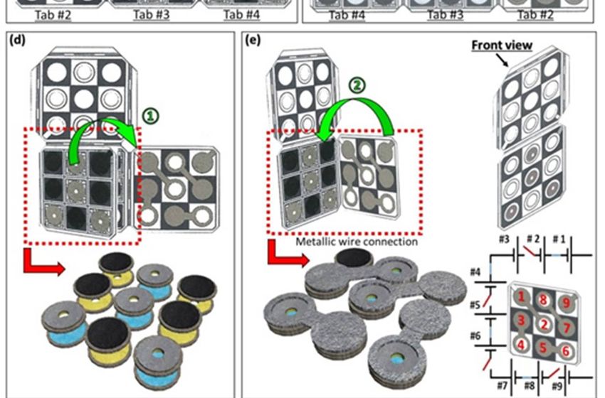
Batteries 2018, 4, 14                                                                               2 of 13

in technology allow us to add patterned conductive and hydrophilic characteristics to paper, increasing
its suitability as a substrate for MFCs [27–29]. The added characteristics allow the effective harvesting
of electrons from the MFCs. In addition, our recent ability to freeze-dry electricity-generating bacterial
cells (or exoelectrogens) in paper allowed a long battery shelf life and the easy activation for a
self-powered device in resource-limited settings [29].
      The sufficient number of the bacterial cells can be stored intact without losing their
electron-generating capacity until used, and be readily activated by various liquids available in
any challenging area. Very recently, we demonstrated an MFC battery stack fabricated on a single
sheet of paper that allowed on-demand activation with human saliva [29,30]. All of the functional
layers for the fuel cell architecture were precisely designed in the paper sheet, and 16 MFC units
were connected in a series to increase the power and output voltage. However, several practical
challenges remain. First, the device (16 cm × 10 cm) was too big to carry around. This is because the
metallic wires and electrical switches had to be patterned and mounted, respectively, on the paper
to connect the MFCs in series, taking up 18% of the device. The electrical switches were necessary,
because individual MFC units must be disconnected until they reach the maximum performance
level. Otherwise, a voltage reversal from the weakest unit will take place, reducing the overall battery
performance [31]. Second, the anodic chamber volume was very limited, because of the other necessary
components (i.e., membrane and cathode) that needed to be integrated into a single sheet of paper.
Since the anodic chamber volume determines the actual surface area for the bacterial attachment,
this limiting factor can substantially reduce the performance of the MFC [26,29].
      In this work, we created a compact three-dimensional (3-D) battery stack through the origami
technique, reducing the overall device size by about 20% (5.6 cm × 5.6 cm) and eliminating the
limitation in controlling the anodic chamber volume (Figure 1a). A two-dimensional (2-D) sheet
of paper was designed and patterned to have folding tabs on which holes (for cathodic reaction
and sample injection, respectively), anodic chambers, an air cathode, and electrical wires were
fabricated (Figure 1b,c). By folding the tabs, nine MFC units were configured and connected in
series (Figure 1d–g). The metallic wires were well designed and patterned on two designated folding
tabs, which upon folding reduced the size compared to previous devices. The specific folding pattern
created the series connection of the nine MFCs. Furthermore, folding and unfolding the device
functioned as an electrical switch for the series connection. The multilayer configuration ensured
that the anodic chamber was occupied throughout the entire device, and also increased the overall
volume and surface area for the bacterial attachments. This innovative platform allowed us to combine
multiple individual batteries into a single, stronger pocket-sized battery stack, making the batteries
easier to transport; it also allowed us to explore designs that are not possible with rigid materials.
Finally, simple batch-fabrication methods (i.e., printing, brushing, and spraying) were applicable for
the mass production of the paper-based MFCs. Freeze-dried Pseudomonas aeruginosa PAO1 in the
conductive and hydrophilic anodic chambers were rehydrated by using wastewater as an organic
activation sample, and the nine MFCs connected in series generated a maximum output voltage of
2.3 V and power of 20 µW, which will be sufficient to operate actual low-power biosensing applications.
This pocket-sized device holds considerable promise as an on-demand power source for use in remote
and resource-limited environments.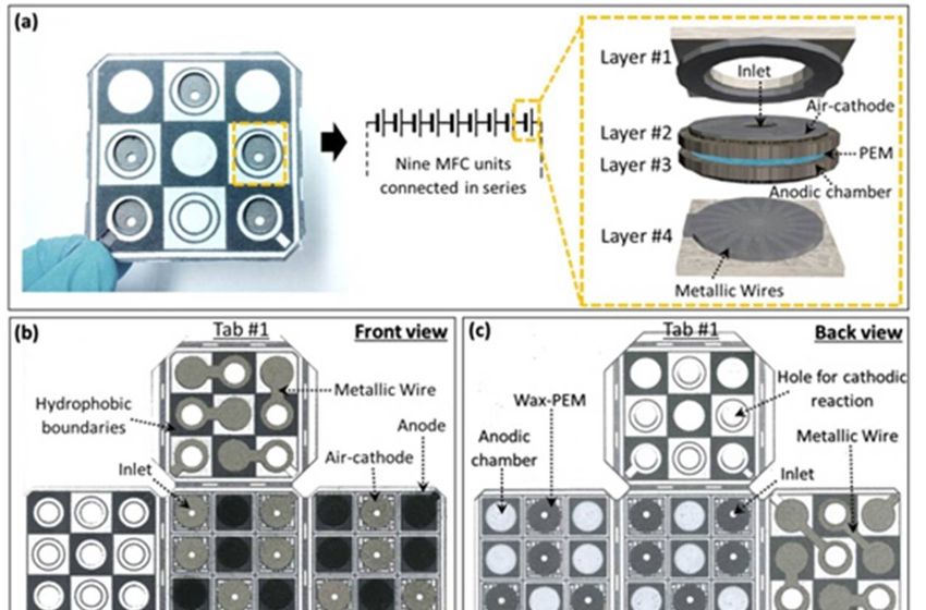
Batteries 2018, 4, 14                                                                                              3 of 13
Batteries 2018, 4, x FOR PEER REVIEW                                                                                    3 of 12

     Figure
       Figure1.1.(a)(a)An
                        Anorigami
                            origamipaper-based
                                    paper-based biobattery    stackand
                                                  biobattery stack  andschematic
                                                                        schematicdiagram
                                                                                   diagram  ofof  a cross-section
                                                                                               a cross-section     of the
                                                                                                                of the
       single unit;    (b) Front and  (c)
     single unit; (b) Front and (c) back  back view  of the two-dimensional   (2-D) sheet  of paper   before  folding;
                                                        the two-dimensional (2-D) sheet of paper before folding;
       (d–f)Folding
     (d–f)   Folding processes    for for
                          processes   the three-dimensional  (3-D) battery
                                           the three-dimensional     (3-D)stack and itsstack
                                                                            battery      metallic
                                                                                              andwireitsconfiguration;
                                                                                                          metallic wire
       (g) Front  and    back view of  the folded battery stack.
     configuration; (g) Front and back view of the folded battery stack.

2. Results and Discussion
     The MFC was based on a two-chambered device configuration consisting of an anode and an air
cathode separated by a proton exchange membrane (PEM) (Figure 1a). The exoelectrogens were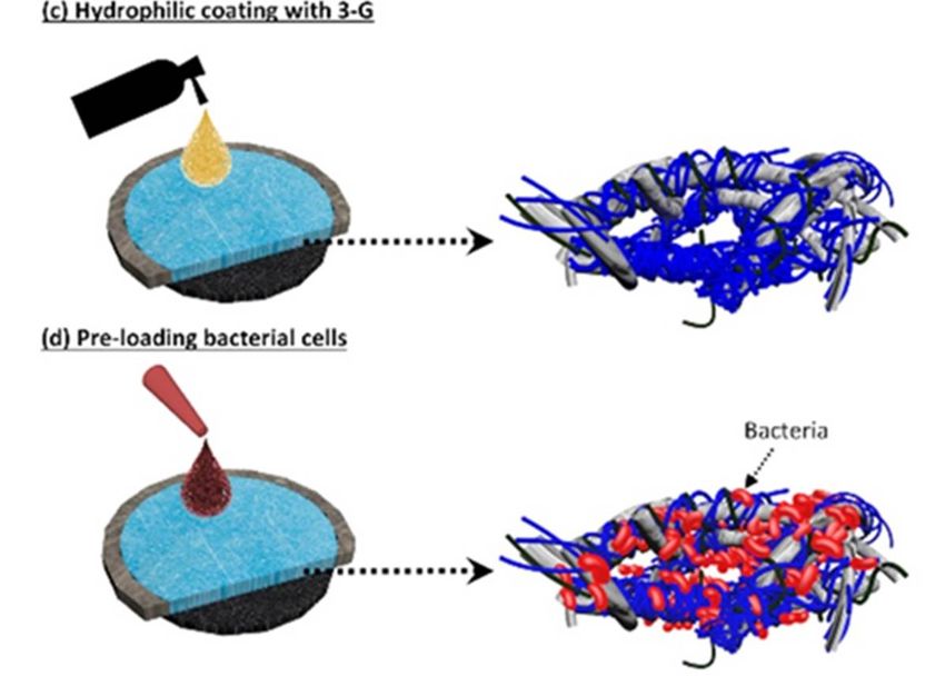
Batteries 2018, 4, 14                                                                              4 of 13

2. Experimental Sections
     Materials: Poly(3,4-ethylened ioxythiophene):polystyrene sulfonate (PEDOT:PSS), 5 wt % Nafion
solution, dimethyl sulfoxide (DMSO), 3-glycidoxypropy-trimethoxysilane (3-G) were purchased from
Sigma-Aldrich. Activated carbon (AC) powders and a nickel conductive spray were obtained from
Cabot Corporation (Boston, MA, USA) and MG Chemicals (Burlington, ON, Canada), respectively.
Whatman 3MM chromatography papers (Philadelphia, PA, USA) were purchased from VWR.
All materials and chemicals were used as received without further treatment.
     Wax patterning on paper: MFC devices were fabricated using a wax printing technique. Specific
device patterns were designed using AutoCAD software, and printed onto the chromatography paper
using Xerox Phaser printer (ColorQube 8570 (Fairfield County, CT, USA)). Then, the printed paper
was placed in an oven set at 150 ◦ C for 30 s, and the hydrophobic wax melted into the paper substrate,
defining device boundaries, forming PEMs, and strengthening the paper while retaining its flexibility.
     Hydrophilic and conductive anodic chambers in paper: A 30-µL mixture of 1 wt % PEDOT:PSS and
5 wt % DMSO was sprayed onto the 2-D paper through a patterned stencil to form anodic chambers
and air-dried for 8 h, which was repeated up to four times to reduce the sheet resistances of the anodes.
To further increase their hydrophilicity, 20 µL of 2 wt % 3-glycidoxypropy-trimethoxysilane was also
sprayed to individual chamber regions and air dried.
     Air cathodes on paper: AC-based air cathodes were formed on paper with a nickel spray, which
provides better conductivity for the cathode. The detailed fabrication processes for the air cathode
on paper were reported in our previous reports [24–26]. In short, 15 mg·cm−2 AC catalysts with a
binder solution were brushed on the wax-based PEM, and subsequently air dried for 24 h (Figure S1).
The binder solution was prepared with (i) 1200 µL of 5 wt % Nafion solution; (ii) 150 µL of deionized
water; and (iii) 600 µL of isopropanol into a beaker, followed by ultrasonication for 1 min.
     Metallic wires on paper: The thin-film plastic stencils for the metal deposition (1/16-inch acrylic
sheets, McMaster-Carr (Aurora, OH, USA) were micromachined by laser cutting (Universal Laser
System VLS 3.5). Nickel metallic wires were then sprayed onto the paper through the stencils.
     Inoculum: Pseudomonas aeruginosa PAO1 were cultured from −80 ◦ C from bacterial glycerol stock
by inoculating 30 mL of LB medium with gentle shaking in the air for 24 h at 35 ◦ C. The LB media
consisted of 10.0 g tryptone, 5.0 g yeast extract, and 5.0 g NaCl per liter. The culture was then
centrifuged at 5000 rpm for 5 min to remove the supernatant. The bacterial cells were re-suspended in
a new medium, and preloaded in the anodic chambers.
     Freeze-drying: After the MFCs were preloaded with bacterial cells, the device was placed in a
freeze dryer (FreeZone Plus 2.5 Liter Cascade Benchtop Freeze Dry System, Labconco, MO, USA) and
the drying operation was performed at a pressure of 0.06 atm for 24 h with freezing, sublimation,
and desorption processes. During the processes, the chamber temperature dropped to −25 ◦ C,
and then progressively increased back to room temperature. The paper MFCs were not affected by the
freeze-drying process.
     Bacterial Fixation and SEM Imaging: The SEM image samples were taken from anodic chambers
with bacteria. They were immediately fixed in 2% glutaraldehyde solution overnight at 4 ◦ C. Samples
were then dehydrated by 5-min serial transfers through 50%, 70%, 80%, 90%, 95%, and 100%
ethanol. Fixed samples were examined using a FESEM (field emission SEM) (Supra 55 VP, Zeiss
(Jena, Germany)).

3. Results and Discussion
     The MFC was based on a two-chambered device configuration consisting of an anode and an
air cathode separated by a proton exchange membrane (PEM) (Figure 1a). The exoelectrogens were
contained in the engineered conductive and hydrophilic anode chambers and freeze-dried until used.
The introduction of wastewater through an inlet connected to the anodic chamber rehydrated the
freeze-dried cells, activating their metabolism and producing electrons and protons. The electrons
were transferred to the conductive paper fibers and moved to the external circuit while the protons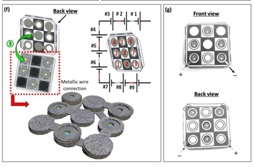
Batteries 2018, 4, x FOR PEER REVIEW                                                                         4 of 12

  contained in the engineered conductive and hydrophilic anode chambers and freeze-dried until used.
Batteries
   The 2018,   4, 14
          introduction
                     of wastewater through an inlet connected to the anodic chamber rehydrated the   5 of 13
  freeze-dried cells, activating their metabolism and producing electrons and protons. The electrons
  were transferred to the conductive paper fibers and moved to the external circuit while the protons
were transported to the cathode through the PEM to maintain the electroneutrality of the system.
  were transported to the cathode through the PEM to maintain the electroneutrality of the system. At
At the air cathode exposed to the air through the large hole (Figure 1a,c), the protons were reduced
  the air cathode exposed to the air through the large hole (Figure 1a,c), the protons were reduced with
with the oxygen, and electrons traveled from the anode.
  the oxygen, and electrons traveled from the anode.
3.1. Conductive and Hydrophilic Anodic Chambers
   2.1. Conductive and Hydrophilic Anodic Chambers
      In order to hold the exoelectrogens in liquid and harvest electrons from the cells
         In order to hold the exoelectrogens in liquid and harvest electrons from the cells distributed by
distributed    by capillary
   capillary action   throughout action
                                     the throughout      the 3-D of
                                          3-D porous structure       porous
                                                                       paper,structure   of fiber
                                                                                each paper   paper,needs
                                                                                                       eachto paper
                                                                                                               be
fiber   needs   to  be  hydrophilic      and   conductive      (Figure  2).
   hydrophilic and conductive (Figure 2). Conducting polymers such as poly(3,4-Conducting     polymers     such as
poly(3,4-ethylenedioxythiophene):poly(styrene
   ethylenedioxythiophene):poly(styrene sulfonate)sulfonate)          (PEDOT:PSS)
                                                            (PEDOT:PSS)    have been have   been
                                                                                       widely usedwidely    used to
                                                                                                     to fabricate
fabricate   conducting
   conducting   papers, aspapers,     as they
                            they possess       possess electrical
                                           controllable    controllable  electrical
                                                                    conductivity     conductivity
                                                                                  ranging           ranging from
                                                                                          from semiconductors
semiconductors
   to metals [32].toMany
                      metalsstudies
                                [32]. Many   studies demonstrated
                                        demonstrated                   that the conductivity
                                                         that the conductivity                 of the PEDOT:PSS
                                                                                   of the PEDOT:PSS       can be
cansubstantially
     be substantially   improved
                  improved            by mixing
                               by mixing   it withit other
                                                     with other   solvents
                                                            solvents such assuch  as dimethyl
                                                                              dimethyl         sulfoxide
                                                                                        sulfoxide  (DMSO)  (DMSO)
                                                                                                             and
and  ethylene
   ethylene     glycol
             glycol    (EG)
                    (EG)      [27–29,33].
                          [27–29,33].

             2. Schematic
        Figure
     Figure                illustration
                2. Schematic            of the
                               illustration  of fabrication steps steps
                                                 the fabrication   for conductive and hydrophilic
                                                                         for conductive           anodic chambers.
                                                                                        and hydrophilic    anodic
     (a)chambers.  (a) Defining Hydrophobic
         Defining Hydrophobic     boundaries, boundaries,     (b) Conductive
                                                 (b) Conductive   engineeringengineering
                                                                               the anodic the anodic(c)
                                                                                          reservoir, reservoir, (c)
                                                                                                        Hydrophilic
        Hydrophilic
     coating          coating ofand
              of the reservoir,  the reservoir,  and (d)exoelectrogens.
                                     (d) pre-loading     pre-loading exoelectrogens.

     Furthermore, its hydrophilicity can be enhanced by adding 3-glycidoxypropy-trimethoxysilane
(3-G) [27–29]. Previously, 3-G/DMSO-modified PEDOT:PSS was used to define conductive and
hydrophilic regions in the paper, which revolutionarily created a new, simple, and scalable fabrication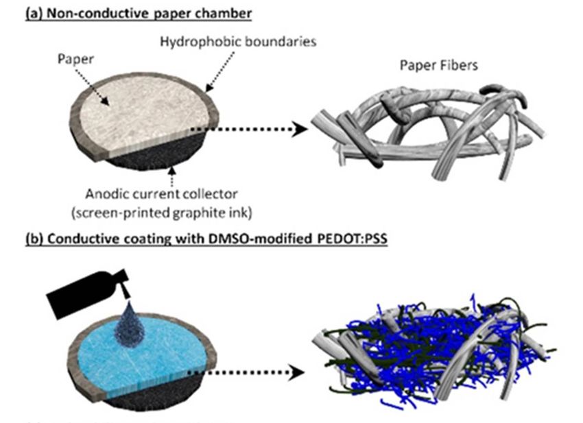
Furthermore, its hydrophilicity can be enhanced by adding 3-glycidoxypropy-trimethoxysilane
Batteries 2018, 4, x FOR PEER REVIEW 5 of 12
(3-G) [27–29]. Previously, 3-G/DMSO-modified PEDOT:PSS was used to define conductive and
hydrophilic regions its
Furthermore, inhydrophilicity
the paper, can which revolutionarily
be enhanced by addingcreated a new, simple, and scalable
3-glycidoxypropy-trimethoxysilane
fabrication
Batteries method
2018,
(3-G) [27–29]. 4, 14 for making
Previously, paper-based printed
3-G/DMSO-modified circuit boards
PEDOT:PSS was used [27].toOur group
define for the 6first
conductive of 13 time
and
applied this technique
hydrophilic regions intothe a paper-based
paper, which MFC, gaining created
revolutionarily greatly aimproved
new, simple, performance
and scalable from a
conductive
fabrication
method for andmethod hydrophilic
making for making
paper-basedanodic chamber
paper-based
printed circuit [29,30,34].
printed circuit
boards InOur
boards
[27]. this
[27].work,
group Our athemore
forgroup batch-fabricable
for the
first time first time
applied
applied
approach wasthisproposed
this technique technique totosimultaneously
to a paper-based a paper-based
MFC, gaining MFC,
define
greatlygaining
nine greatly
anodic
improved improved
chambers
performance performance
onfromthe a2-D from
non-conducting
conductive and a
conductive
paper sheet (Figure
hydrophilic and hydrophilic
anodic2a). anodic
The DMSO-modified
chamber chamber [29,30,34].
PEDOT:PSS
[29,30,34]. In this work, In this work,
mixture (Figure
a more batch-fabricable a more batch-fabricable
2b) andwas
approach theproposed
3-G solution
approach
(Figure 2c) were was proposed
to simultaneously poured
define tonine
into simultaneously
a anodic gun define
spray chambers glasson nine
the anodic
bottle, 2-D and chambers
sprayed onto
non-conducting on the 2-Dentire
the
paper non-conducting
sheet surface2a).
(Figure of the
paper
The sheet (Figure 2a).
DMSO-modified The DMSO-modified
PEDOT:PSS mixture PEDOT:PSS
(Figure 2b) and mixture
the 3-G (Figure 2b)
solution and the
(Figure 2c) 3-G solution
were poured
paper. The solution slowly but efficiently absorbed into the paper. We then could form conductive
(Figure 2c) were poured intoand
a spray gunontoglass
thebottle, and sprayed onto
paper.the entire surface of the
and into a spray
hydrophilic gun glass
anodic bottle,
reservoirs sprayed
without blockingentireanysurface of the
of the paper’s The
poressolution
(Figureslowly but This
3a,b).
paper. The
efficiently solution
absorbed slowly
into the but efficiently
paper. We then absorbed
could forminto the paper.
conductive We
and then could
hydrophilic form
anodic conductive
reservoirs
structure
and
enabled conformal
hydrophilic anodic
and densely
reservoirs
packed
without
biofilm
blocking
formation (Figure 2d,c). The sheet resistance
without blocking any of the paper’s pores (Figure 3a,b).anyThisofstructure
the paper’senabledpores (Figure and
conformal 3a,b). This
densely
(~350 ohm·sqenabled
structure
−1 ) of theconformal
engineered and anodic
densely chamber
packed was measured
biofilm formation by using
(Figure − 1
a four-point
2d,c). The sheet probe method,
resistance
packed biofilm formation (Figure 2d,c). The sheet resistance (~350 ohm·sq ) of the engineered anodic
and(~350
did notohm·sq significantly change even
−1) of the engineered with repeated extensive bymechanical deformations (up to 80
chamber was measured by usinganodic chamber
a four-point probewasmethod,
measured and using
did nota significantly
four-point probe method,
change even
bending
and
withdid cycles)
repeated (Figure
extensive4).mechanical
not significantly This indicates
change even withthat the
repeated
deformations (upconductive
extensive
to 80 bending and hydrophilic
mechanical
cycles) chemical
deformations
(Figure 4). This(up coating
to 80
indicates is
stable and
bending resilient
cycles) on paper
(Figure 4). substrates.
This indicates that the conductive and hydrophilic
that the conductive and hydrophilic chemical coating is stable and resilient on paper substrates. chemical coating is
stable and resilient on paper substrates.
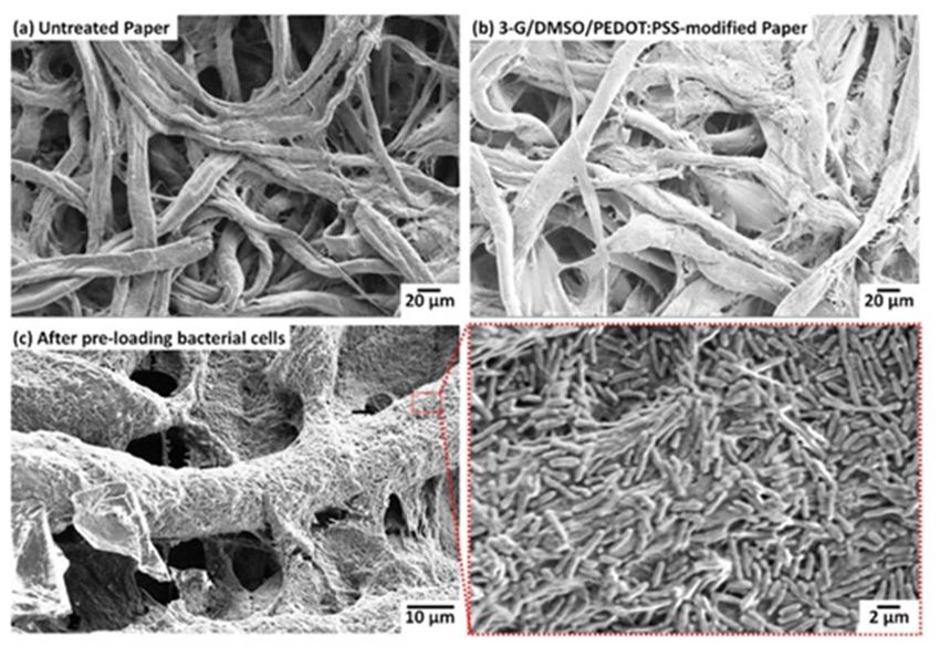
Figure 3. SEM (Scanning electron microscope) images of the anodic chamber. (a) Non-treated paper
Figure 3. SEM (Scanning electron microscope) images of the anodic chamber. (a) Non-treated
Figure
and 3. SEM (Scanning electron microscope) images of the anodic chamber. (a) Non-treated 3-paper
paper3-G/DMSO/PEDOT:PSS-treated paper (b)
and 3-G/DMSO/PEDOT:PSS-treated without
paper (b) and (c) with
without bacterial
and (c) cells. 3-G:cells.
with bacterial
andglycidoxypropy-trimethoxysilane;
3-G/DMSO/PEDOT:PSS-treated DMSO: paper (b)dimethyl
without sulfoxide;
and (c) with bacterial cells. 3-G: 3-
3-G: 3-glycidoxypropy-trimethoxysilane; DMSO: dimethyl sulfoxide;PEDOT:PSS:
PEDOT:PSS: poly(3,4-
poly(3,4-
glycidoxypropy-trimethoxysilane; DMSO:
ethylenedioxythiophene):poly(styrene sulfonate). dimethyl sulfoxide; PEDOT:PSS: poly(3,4-
ethylenedioxythiophene):poly(styrene sulfonate).
ethylenedioxythiophene):poly(styrene sulfonate).
Figure 4.
Figure Sheet resistance
4. Sheet resistance of
of the
the anodic
anodic chamber
chamber vs. the
the number
number of
of bending
bending cycles.
cycles.
Figure 4. Sheet resistance of the anodic chamber vs. the number of bending cycles.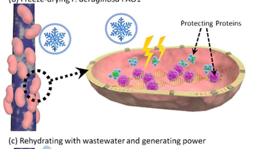
Batteries 2018, 4, 14                                                                                                  7 of 13

      Batteries 2018, 4, xBacterial
3.2. Freeze-Drying         FOR PEER Cells
                                    REVIEW                                                                       6 of 12

     For
      2.2. on-demand
           Freeze-Drying power
                           Bacterialgeneration
                                     Cells         and a long shelf life for the biobattery, the exoelectrogens
were preloaded       and    freeze-dried    in  the  engineered anodic chambers (Figure 5). The preloaded
            For on-demand power generation and a long shelf life for the biobattery, the exoelectrogens were
exoelectrogens
      preloaded covered        the conductive
                    and freeze-dried      in the paper    fibers anodic
                                                   engineered     three-dimensionally
                                                                            chambers (Figure and 5).
                                                                                                   conformally,
                                                                                                       The preloadedforming
densely   packed biofilms
      exoelectrogens     covered(Figure   3c and Figure
                                  the conductive           5a). Then,
                                                    paper fibers         the cells wereand
                                                                  three-dimensionally      freeze-dried,
                                                                                                conformally,keeping
                                                                                                               formingthem
intactdensely
       throughpacked
                  the freezing,
                          biofilmssublimation,
                                   (Figures 3c andand5a).
                                                       desorption
                                                          Then, the processes
                                                                     cells were (Figure     5b). Freeze-drying
                                                                                   freeze-dried,                    has been
                                                                                                  keeping them intact
widelythrough
        used forthethefreezing,  sublimation,
                         long-term              and desorption
                                      preservation    of bacterialprocesses    (Figure
                                                                    cells [35,36].      5b). Freeze-drying
                                                                                      Although                has been
                                                                                                  not all bacterial   strains
      widely
survive       used for the
         the process,     andlong-term   preservation
                               further studies         of bacterial cells
                                                  on exoelectrogens     are[35,36]. Although
                                                                              required,        not all bacterial
                                                                                         freeze-drying    allows strains
                                                                                                                   the MFC
      survivetothe
technology          process,
                 find           and furtherand
                        more applicable      studies  on exoelectrogens
                                                 potentially                 are required, as
                                                               realizable applications      freeze-drying
                                                                                               a practical allows    the
                                                                                                            and accessible
      MFC technology to find more applicable and potentially realizable applications as a practical and
power supply in remote and resource-constrained environments. We previously demonstrated that the
      accessible power supply in remote and resource-constrained environments. We previously
wild-type Pseudomonas aeruginosa PAO1 can be freeze-dried and rehydrated so that their metabolism
      demonstrated that the wild-type Pseudomonas aeruginosa PAO1 can be freeze-dried and rehydrated
generates   power
      so that        (Figure 5c) generates
              their metabolism     [29]. Furthermore,     our 5c)
                                               power (Figure   recent
                                                                   [29].literature
                                                                         Furthermore,survey
                                                                                         our indicates   that P.survey
                                                                                              recent literature   aeruginosa
can produce    protecting     proteins under    oxidative   stress such   as  freeze-drying    (Figure  5b)
      indicates that P. aeruginosa can produce protecting proteins under oxidative stress such as freeze-   [37,38],   which
will probably   improve      their survival   rate  during   the process.
      drying (Figure 5b) [37,38], which will probably improve their survival rate during the process.

      FigureFigure  5. Schematic illustration of bacteria storage, their rehydration with wastewater, and their
              5. Schematic    illustration of bacteria storage, their rehydration with wastewater, and their power
             power generation. (a) Pre-loading bacterial cells in the anodic reservoir, (b) freeze-drying the device
      generation. (a) Pre-loading bacterial cells in the anodic reservoir, (b) freeze-drying the device with the
             with the cells, and (c) rehydrating the cells for on-demand power generation.
      cells, and (c) rehydrating the cells for on-demand power generation.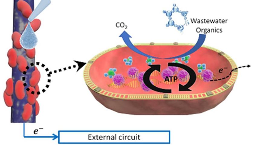
Batteries 2018, 4, x FOR PEER REVIEW 7 of 12
Batteries 2018, 4, 14 8 of 13
The rehydration of freeze-dried exoelectrogens is a critical step for on-demand power generation
[39].The
Among many factors
rehydration affecting cell
of freeze-dried viability during
exoelectrogens is arehydration, thefor
critical step media is important
on-demand power in
restoring water to the dried cells. Our previous report showed that human saliva and bacterial
generation [39]. Among many factors affecting cell viability during rehydration, the media is important media
could
in activate
restoring the bacterial
water metabolism
to the dried cells. Our[29]. In this report
previous work, we testedthat
showed organic
human wastes as and
saliva a rehydration
bacterial
media, which are readily available in resource-limited areas. This result shows
media could activate the bacterial metabolism [29]. In this work, we tested organic wastesthe potential of MFCs
as a
to harness energy
rehydration media,from a wider
which range ofavailable
are readily soluble and renewable biomasses
in resource-limited areas.forThis
practical
resultapplications.
shows the
Further investigation
potential of bacterial
of MFCs to harness energy survival
from a abilities afteroffreeze-drying
wider range and during
soluble and renewable storage and
biomasses for
rehydration will be our future work.
practical applications. Further investigation of bacterial survival abilities after freeze-drying and
during storage and rehydration will be our future work.
2.3. Power Generation from a Single MFC Unit
3.3. Power Generation
We first from a Single
demonstrated MFC Unit
fabrication and operation of a single MFC unit (Figures 6 and S1). A 3-D
MFCWe was created
first by folding
demonstrated a 2-D paper
fabrication andsubstrate
operationwith
of atwo functional
single MFC unit folding
(Figuretabs; oneFigure
6 and tab forS1).
an
anodic bacterial respiration, and the other for a cathodic reaction. The anodic tab was engineered
A 3-D MFC was created by folding a 2-D paper substrate with two functional folding tabs; one tab for to
have
an a conductive
anodic and hydrophilic
bacterial respiration, feature
and the otherwith
for aacathodic
carbon current collector,
reaction. while
The anodic the
tab cathodic
was tab was
engineered to
composed
have of a wax-based
a conductive PEM, anfeature
and hydrophilic air-cathode
with acatalyst layer, and
carbon current a nickel
collector, current
while collectortab
the cathodic (Figure
was
S2).
composed of a wax-based PEM, an air-cathode catalyst layer, and a nickel current collector (Figure S2).
Figure6.6. (a)
Figure (a) Photos
Photos and
and (b)
(b)schematics
schematicsof
ofthe
thesingle
singlemicrobial
microbialfuel
fuelcell
cell(MFC)
(MFC)unit.
unit.
Previously, many
Previously, many studies
studiesdemonstrated
demonstrated thatthat
the the
wax-based
wax-basedPEM PEM can work
can aswork
an ion asexchange
an ion
exchange membrane, separating the anodic part from the cathode while allowing protons through
membrane, separating the anodic part from the cathode while allowing protons to pass to pass
[18,19,25,26].
through The cathodic
[18,19,25,26]. surface surface
The cathodic was exposed to the air
was exposed for air
to the a maximized cathodic
for a maximized reaction,
cathodic and a
reaction,
and a hole was made through the entire cathodic tab to allow the sample to be introduced toafter
hole was made through the entire cathodic tab to allow the sample to be introduced to the anode the
folding.
anode First,
after we dropped
folding. various
First, we droppedconcentrations of the exoelectrogens
various concentrations in L-broth (LB)
of the exoelectrogens media in(LB)
in L-broth the
engineered anodic chamber through the inlet on the cathode
media in the engineered anodic chamber through the inlet on the cathode side, and measured the side, and measured the
polarization/power curves with different external load resistances (Figure 7a).
polarization/power curves with different external load resistances (Figure 7a). The optical density atThe optical density at
600nm
600 nm(OD600)
(OD600)was wasused
used toto control
control thethe concentration.
concentration. Given
Given thatthat
the the maximum
maximum powerpower density
density of a
of a fuel
fuel cell system is obtained when the external resistance is equal to the internal
cell system is obtained when the external resistance is equal to the internal resistance of the system [40],resistance of the
system [40], Figure 7a shows that the internal resistances (~4 kΩ) of our MFCs
Figure 7a shows that the internal resistances (~4 kΩ) of our MFCs were quite consistent with the were quite consistent
with the increased
increased bacterial concentrations,
bacterial concentrations, while their while
powertheir power and
and current current
densities densities
were enhanced were enhanced
significantly.
significantly. This indicates that the device was well fabricated, with no
This indicates that the device was well fabricated, with no variation, and the folding procedurevariation, and the folding
did
procedure
not have any did not have
negative any on
effects negative effects
the device on the device
performance. Theperformance.
maximum power The maximum
and currentpower and
densities
current densities of 1.23 μW·cm−2 and 30 μA·cm−2 were obtained, respectively, from the 1.0 OD600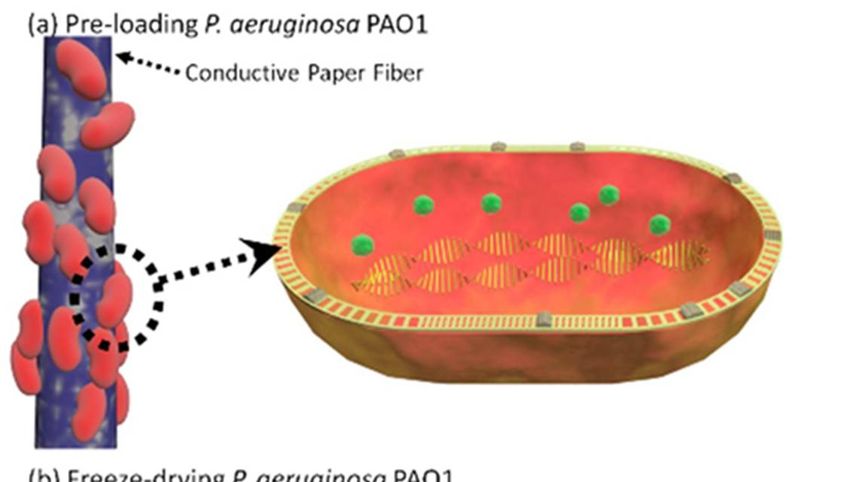
Batteries 2018, 4, x FOR PEER REVIEW 8 of 12
concentration of the bacterial culture (Figure 7a). A higher concentration of culture than the 1.0
OD600 was too viscous to allow the solution to flow through the paper matrix, decreasing the MFC
performance. Unless otherwise specified, the 1.0 OD600 concentration of the bacterial culture was
Batteries 2018, 4, 14 9 of 13
used for the other experiments. The conductive and hydrophilic engineering of the paper with the 3-
G/DMSO-modified PEDOT:PSS substantially improved the MFC performance, as the bacterial cells
in 1.23
of media µW ·cm−easily
were 30 µA·cm−horizontally
2 anddistributed 2 were obtained,
and vertically throughout
respectively, from thethe1.0
entire hydrophilic
OD600 anode,
concentration
and
of thethe cells were
bacterial attached
culture (Figureto7a).
the Aconductive paper fibers,ofharvesting
higher concentration culture than electrons from the
the 1.0 OD600 was media
too
(Figure 7b). This 3-D anodic scaffold
viscous to allow the solution to flow through extracted the collective electrons from all of the bacterial
paper matrix, decreasing the MFC performance. cells in
the anodic
Unless chamber.
otherwise The maximum
specified, the 1.0 OD600 power density from
concentration the
of the engineered
bacterial anodic
culture chamber
was used was
for the 1.6
other
μW·cm−2, which
experiments. The was about three
conductive times higherengineering
and hydrophilic than that ofofthe
thenon-conducting paper MFC.
paper with the 3-G/DMSO-modified
After we
PEDOT:PSS confirmedimproved
substantially the optimal concentration
the MFC of bacterial
performance, cells and
as the bacterial engineered
cells the anodic
in media were easily
chamber forhorizontally
distributed the high MFC andperformance, the bacterial
vertically throughout thecells were
entire preloadedanode,
hydrophilic in the and
engineered
the cellsanodic
were
chamber and freeze-dried for storage. Then, the device with the cells was stored
attached to the conductive paper fibers, harvesting electrons from the media (Figure 7b). This 3-D in our lab set at 22.8
°C andscaffold
anodic 45% of extracted
relative humidity for three
the collective days (Figure
electrons from allS3a).
of theFor on-demand
bacterial cells inpower generation,
the anodic chamber. the
freeze-dried
The maximum bacterial
powercells werefrom
density rehydrated with wastewater
the engineered obtainedwas
anodic chamber from1.6theµW ·cm−2 , which was
Binghamton-Johnson
City Joint
about threeSewage Treatment
times higher than Plant
that of(Figure S3b).
the non-conducting paper MFC.
Figure7.7.Polarization
Figure Polarizationcurves
curves and
andpower
poweroutputs
outputs measured
measured from
fromthe
thesingle
singleMFCs
MFCs(a)(a)with
withdifferent
different
concentrations of non-freeze-dried bacterial cells; (b) with 1.0 OD600 culture of non-freeze-dried
concentrations of non-freeze-dried bacterial cells; (b) with 1.0 OD600 culture of non-freeze-dried cells cells
inthe
in theanodic
anodicchamber
chamberwith
withororwithout
withoutPEDOT:PSS
PEDOT:PSStreatment;
treatment;and
and(c)
(c)with
withrehydrated
rehydratedfreeze-dried
freeze-dried
cells (1.0
cells (1.0 OD600
OD600 culture)
culture) in
in aa different
different liquid.
liquid.AAcontrol
controlwithout
withoutbacterial cells
bacterial was
cells also
was prepared
also preparedfor
comparison.
for comparison.
After we confirmed the optimal concentration of bacterial cells and engineered the anodic chamber
for the high MFC performance, the bacterial cells were preloaded in the engineered anodic chamber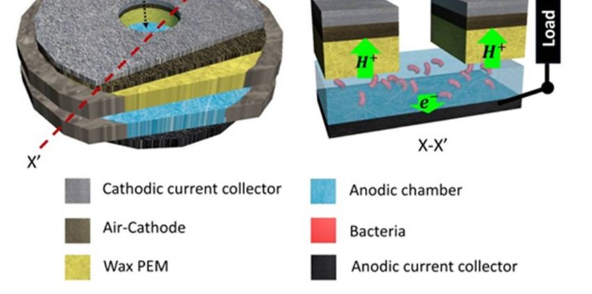
Batteries 2018, 4, 14 10 of 13
and freeze-dried for storage. Then, the device with the cells was stored in our lab set at 22.8 ◦ C and 45%
of relative
Batteries humidity
2018, for three
4, x FOR PEER REVIEWdays (Figure S3a). For on-demand power generation, the freeze-dried 9 of 12
bacterial cells were rehydrated with wastewater obtained from the Binghamton-Johnson City Joint
Sewage The power density
Treatment harvested
Plant (Figure S3b).from the wastewater was comparable to the LB media, and the
current
Thedensity was even
power density higher than
harvested fromthethe
media (Figure 7c).
wastewater wasThe control MFC
comparable without
to the bacterial
LB media, and cells
the
produced much smaller current and power outputs than the samples, indicating that
current density was even higher than the media (Figure 7c). The control MFC without bacterial cells the energy
generationmuch
produced was mainly
smallergenerated from
current and the bacterial
power outputsmetabolism and theirindicating
than the samples, electron transfer
that thereactions.
energy
generation was mainly generated from the bacterial metabolism and their electron transfer reactions.
2.4. Power Generation from a Nine-Cell MFC Stack
3.4. Power Generation from a Nine-Cell MFC Stack
The origami-inspired fabrication of the single MFC unit was extended to form a nine-MFC stack
The 1a).
(Figure origami-inspired
Basically, thefabrication
MFCs were of the singleon
formed MFCtwounit was extended
folding to formof
tabs consisting a nine-MFC
the anodicstack and
(Figure
cathodic 1a).layers
Basically, the MFCs
(Figure 1b,c). were
Each formed
foldingon tabtwowasfolding
5.6 cm tabs consisting
× 5.6 cm, andofincluded
the anodicnineandanodic
cathodic or
layers
cathodic (Figure
components1b,c). Each
(Figurefolding
S4). tab
Twowas more cm × 5.6
5.6 folding cm,
tabs forand
theincluded
electricalnine
seriesanodic or cathodic
connections were
components
added. By folding (Figure theS4).
tabsTwo withmore folding
a certain tabsalong
pattern for the electrical creases,
predefined series connections
nine MFCs were were created,
added.
By
andfolding
at thethe same tabs withthey
time, a certain
were pattern along predefined
all connected creases,
in series (Figure nine MFCs were created, and at the
1d–g).
same We time,first
they were all connected
preloaded the bacterial in series (Figure
cells on 1d–g).anodic chamber and freeze-dried them. For
each MFC
easyWe and first preloaded
compact the bacterial
storage, the MFCs cellswere
on each
foldedMFC anodic
until used.chamber
Since theandcells
freeze-dried
were notthem. For easy
activated and
and
the compact
external loads storage, thenot
were MFCs were folded
connected, until used.
the folding did not Since theaffect
later cells the
wereMFC not activated
operation.and For theon-
demandloads
external power weregeneration,
not connected,we unfolded
the folding thediddevice andaffect
not later introduced
the MFC25operation.
μL of wastewater
For on-demandas an
power generation,
activation liquid we unfolded
to each thenine
of the device and introduced
anodic chambers. 25 WeµL of wastewater
waited 5 min for as the
an activation
cells to beliquid
fully
to each of theand
rehydrated ninebeanodic
ready chambers.
for electronWe waited Then,
transfer. 5 min wefor refolded
the cells tothebedevice,
fully rehydrated
forming nine andMFCs
be readyand
connecting
for them in series.
electron transfer. Then, we refolded the device, forming nine MFCs and connecting them in series.
Fiverepeated
Five repeatedmeasurements
measurements withwith other
other MFC MFC stacks
stacks hadhad a relative
a relative standard
standard deviation
deviation of lessofthan
less
3.5%. The open
than 3.5%. The circuit voltagevoltage
open circuit of the battery stack was
of the battery stack2.3was
V, and
2.3 its
V, maximum power and
and its maximum current
power and
were 20 µW
current were and 2025μWµA,andrespectively (Figure 8), which
25 μA, respectively (Figurecan 8),bewhich
furthercanimproved
be furtherby improved
simply adding more
by simply
adding
MFCs and moretabsMFCswithinand tabs and
a small within a small
single unit. and
Thissingle
MFC stack unit. This
platformMFCisstack
a greatplatform
example is of
a how
great
example
easily paper of can
howbeeasily
foldedpaper can be folded
and unfolded and
with the unfolded
origami with the
technique, andorigami technique,
how multiple and how
batteries can
multiple
be combined batteries can be combined
in a compact manner. in a compact manner.
Figure8.8.Polarization
Figure Polarizationcurves
curvesand
andoutput
outputpowers
powersmeasured
measuredfrom
fromthe
thenine-MFC
nine-MFCstack
stackwith
withwastewater
wastewater
activation liquid.
activation liquid.
3. Experimental Sections
Experimental Sections
Materials: Poly(3,4-ethylened ioxythiophene):polystyrene sulfonate (PEDOT:PSS), 5 wt % Nafion
solution, dimethyl sulfoxide (DMSO), 3-glycidoxypropy-trimethoxysilane (3-G) were purchased
from Sigma-Aldrich. Activated carbon (AC) powders and a nickel conductive spray were obtained
from Cabot Corporation (Boston, MA, USA) and MG Chemicals (Burlington, ON, Canada),Batteries 2018, 4, 14 11 of 13
4. Conclusions
We created an origami-inspired paper MFC stack, producing a maximum power and current of
20 µW and 25 µA, respectively. Hydrophilic and conductive anodic chambers were formed in paper
with 3-G/DMSO/PEDOT:PSS to improve bacterial biofilm formation and their metabolism, ultimately
increasing the MFC performance. We also developed batch-fabrication processes for constructing
multi-MFC units on a single sheet of paper. By folding, the 2-D paper formed 3-D MFCs, and connected
them in series. Folding and unfolding acted as an electrical switch for the whole MFC stack operation.
Freeze-drying was applied to store the bacterial cells, and rehydration generated on-demand power.
In this work, we specifically used wastewater as a rehydration media to activate the freeze-dried
bacterial cells and harvest bioelectricity from bacterial metabolism. The proposed origami technique
revolutionized the fabrication, operation, and application of the paper-based MFCs, which can move
this technique beyond the realm of conceptual research and advance its translational potential toward
practical, real-world applications.
Supplementary Materials: The following are available online at http://www.mdpi.com/2313-0105/4/2/14/s1,
Figure S1: Fabrication processes, Figure S2: SEM images of the compartments, Figure S3: SEM images of bacteria,
Figure S4: Device dimensions.
Acknowledgments: This work is supported by NSF (ECCS #1503462, IOS #1543944, & ECCS #1703394) and the
SUNY Binghamton Research Foundation (SE-TAE).
Author Contributions: M.M. performed the experiments, analyzed the data and prepared the first draft; S.C. wrote
the paper.
Conflicts of Interest: The authors declare no conflict of interest.
References
1. Chaturvedi, V.; Verma, P. Microbial fuel cell: A green approach for the utilization of waste for the generation
of bioelectricity. Bioresour. Bioprocess. 2016, 3, 38. [CrossRef]
2. Li, S.; Cheng, C.; Thomas, A. Carbon-based microbial fuel cell electrodes: From conductive supports to
active catalysts. Adv. Mater. 2017, 29, 1602547. [CrossRef] [PubMed]
3. Sun, M.; Zhai, L.-F.; Li, W.-W.; Yu, H.-Q. Harvest and utilization of chemical energy in wastes by microbial
fuel cells. Chem. Soc. Rev. 2016, 45, 2847–2870. [CrossRef] [PubMed]
4. Babauta, J.; Renslow, R.; Lewandowski, Z.; Beyenal, H. Electrochemically active biofilms: Facts and fiction.
A review. Biofouling 2013, 28, 789–812. [CrossRef] [PubMed]
5. Logan, B.E. Scaling up microbial fuel cells and other bioelectrochemical systems. Appl. Microbiol. Biotechnol.
2010, 85, 1665–1671. [CrossRef] [PubMed]
6. Shantaram, A.; Beyenal, H.; Raajan, R.; Veluchamy, A.; Lewandowski, Z. Wireless sensors powered by
microbial fuel cells. Environ. Sci. Technol. 2005, 1, 5037–5042. [CrossRef]
7. Choi, S. Microscale microbial fuel cells: Advances and challenges. Biosens. Bioelectron. 2015, 69, 8–25.
[CrossRef] [PubMed]
8. Qian, F.; Morse, D.E. Miniaturizing microbial fuel cells. Trends Biotechnol. 2011, 29, 62–69. [CrossRef]
[PubMed]
9. Wang, H.; Bernarda, A.; Huang, C.; Lee, D.; Chang, J. Micro-sized microbial fuel cell: A mini-review. Bioresour.
Technol. 2011, 102, 235–243. [CrossRef] [PubMed]
10. Jiang, H.; Ali, M.A.; Xu, Z.; Halverson, L.J.; Dong, L. Integrated microfluidic flow-through microbial fuel
cells. Sci. Rep. 2017, 7, 41208. [CrossRef] [PubMed]
11. Siu, C.; Chiao, M. A microfabricated PDMS microbial fuel cell. J. Microelectromech. Syst. 2008, 17, 1329–1341.
[CrossRef]
12. Qian, F.; Baum, M.; Gu, Q.; Morse, D.E. A 1.5 µL microbial fuel cell for on-chip bioelectricity generation.
Lab Chip 2009, 9, 3076–3081. [CrossRef] [PubMed]
13. Fraiwan, A.; Lee, H.; Choi, S. A multi-Anode paper-based microbial fuel cell: A potential power source for
disposable biosensors. IEEE Sens. J. 2014, 14, 3385–3390. [CrossRef]Batteries 2018, 4, 14 12 of 13
14. Thom, N.K.; Lewis, G.G.; DiTucci, M.J.; Phillips, S.T. Two general designs for fluidic batteries in paper-based
microfluidic devices that provide predictable and tunable sources of power for on-chip assays. RSC Adv.
2013, 3, 6888–6895. [CrossRef]
15. Phillips, S.T.; Lewis, G.G. The expanding role of paper in point-of-care diagnostics. Expert Rev. Mol. Diagn.
2014, 14, 123–125. [CrossRef] [PubMed]
16. Mabey, D.; Peeling, R.W.; Ustianowski, A.; Perkins, M.D. Diagnostics for the developing world.
Nat. Rev. Microbiol. 2004, 2, 231–240. [CrossRef] [PubMed]
17. Veerubhotla, R.; Das, D.; Pradhan, D. A flexible and disposable battery powered by bacteria using eyeliner
coated paper electrodes. Biosens. Bioelectron. 2017, 94, 464–470. [CrossRef] [PubMed]
18. Lee, S.H.; Ban, J.Y.; Oh, C.-H.; Park, H.-K.; Choi, S. A solvent-free microbial-activated air cathode battery
paper platform made with pencil-traced graphite electrodes. Sci. Rep. 2016, 6, 28588. [CrossRef] [PubMed]
19. Veerubhotla, R.; Bandopadhyay, A.; Das, D.; Chakraborty, S. Instant power generation from an air-breathing
paper and pencil based bacterial bio-fuel cell. Lab Chip 2015, 15, 2580–2583. [CrossRef] [PubMed]
20. Zuo, K.; Liu, H.; Zhang, Q.; Liang, P.; Huang, X.; Vecitis, C.D. A single-use paper-shaped microbial fuel cell
for rapid aqueous biosensing. ChemSusChem 2015, 8, 2035–2040. [CrossRef] [PubMed]
21. Winfield, J.; Chambers, L.D.; Rossiter, J.; Greenman, J.; Ieropoulos, I. Urine-activated origami microbial fuel
cells to signal proof of life. J. Mater. Chem. A 2015, 3, 7058–7065. [CrossRef]
22. Fraiwan, A.; Mukherjee, S.; Sundermier, S.; Lee, H.-S.; Choi, S. A paper-based Microbial Fuel Cell: Instant
battery for disposable diagnostic devices. Biosens. Bioelectron. 2013, 49, 410–414. [CrossRef] [PubMed]
23. Fraiwan, A.; Choi, S. Bacteria-Powered Battery on Paper. Phys. Chem. Chem. Phys. 2014, 16, 26288–26293.
[CrossRef] [PubMed]
24. Lee, H.; Choi, S. An origami paper-based bacteria-powered battery. Nano Energy 2015, 15, 549–557. [CrossRef]
25. Fraiwan, A.; Kwan, L.; Choi, S. A Disposable Power Source in Resource-limited Environments: A Paper-based
Biobattery Generating Electricity from Wastewater. Biosens. Bioelectron. 2016, 85, 190–197. [CrossRef]
[PubMed]
26. Gao, Y.; Choi, S. Stepping Towards Self-powered Papertronics: Integrating Biobatteries into a Single Sheet of
Paper. Adv. Mater. Technol. 2017, 2, 1600194. [CrossRef]
27. Hamedi, M.M.; Ainla, A.; Guder, F.; Christodouleas, D.C.; Fernandez-Abedul, M.; Whitesides, G.M.
Integrating Electronics and Microfluidics on Paper. Adv. Mater. 2016, 28, 5054–5063. [CrossRef] [PubMed]
28. Hamedi, M.M.; Campbell, V.E.; Rothemund, P.; Guder, F.; Christodouleas, D.C.; Bloch, J.; Whitesides, G.M.
Electrically Activated Paper Actuators. Adv. Funct. Mater. 2016, 26, 2446–2453. [CrossRef]
29. Mohammadifar, M.; Choi, S.; Papertronics, A. On-demand and Disposable Biobattery: Saliva-activated
Electricity Generation from Lyophilized Exoelectrogens pre-inoculated on Paper. Adv. Mater. Technol. 2007.
in print. [CrossRef]
30. Mohammadifar, M.; Zhang, K.; Choi, S. A saliva-powered paper biobattery for disposable biodevices.
In Proceedings of the 2017 IEEE 30th International Conference on Micro Electro Mechanical Systems (MEMS),
Las Vegas, NV, USA, 22–26 January 2017; pp. 121–124.
31. Oh, S.-E.; Logan, B.E. Voltage reversal during microbial fuel cell stack operation. J. Power Source 2007, 167,
11–17. [CrossRef]
32. Lee, C.; Lai, K.; Lin, C.; Li, C.; Ho, K.; Wu, C.; Lau, S.; He, H., Jr. A paper-based electrode using a graphene
dot/PEDOT:PSS composite for flexible solar cells. Nano Energy 2017, 36, 260–267. [CrossRef]
33. Huang, J.; Kekuda, D.; Chu, C.; Ho, K. Electrochemical characterization of the solvent-enhanced conductivity
of poly(3,4-ethylenedioxythiophene) and its application in polymer solar cells. J. Mater. Chem. 2009, 19,
3704–3712. [CrossRef]
34. Gao, Y.; Hassett, D.; Choi, S. Rapid Characterization of Bacterial Electrogenicity Using a Single-Sheet
Paper-based Electrofluidic Array. Front. Bioeng. Biotechnol. 2017, 5, 44. [CrossRef] [PubMed]
35. Miyamoto-Shinohara, Y.; Sukenobe, J.; Imaizumi, T.; Nakahara, T. Survival of freeze-dried bacteria. J. Gen.
Appl. Microbiol. 2008, 54, 9–24. [CrossRef]
36. Wenfeng, S.; Gooneratne, R.; Glithero, N.; Weld, R.J.; Pasco, N. Appraising freeze-drying for storage of
bacteria and their ready access in a rapid toxicity assessment assay. Appl. Microbiol. Biotechnol. 2013, 97,
10189–10198. [CrossRef] [PubMed]Batteries 2018, 4, 14 13 of 13
37. Doberenz, S.; Eckweiler, D.; Reichert, O.; Jensen, V.; Bunk, B.; Sproer, C.; Kordes, A.; Frangipani, E.; Luong, K.;
Korlach, J.S.; et al. Identification of a Pseudomonas aeruginosa PAO1 DNA Methyltransferase, Its Targets,
and Physiological Roles. mBio 2017, 8, e02312-16. [CrossRef] [PubMed]
38. Whelan, D.R.; Hiscos, T.J.; Rood, J.I.; Bambery, K.R.; Mcnaughton, D.; Wood, B.R. Detection of an en masse
and reversible B- to A-DNA conformational transition in prokaryotes in response to desiccation. J. R.
Soc. Interface 2014, 11, 20140454. [CrossRef] [PubMed]
39. Costa, E.; Usall, J.; Teixido, N.; Garcia, N.; Vinas, I. Effect of protective agents, rehydration media and
initial cell concentration on viability of Pantoea agglomerans strain CPA-2 subjected to freeze-drying.
J. Appl. Microbiol. 2000, 89, 793–800. [CrossRef] [PubMed]
40. Fan, Y.; Sharbrough, E.; Liu, H. Quantification of the Internal Resistance Distribution of Microbial Fuel Cells.
Environ. Sci. Technol. 2008, 42, 8101–8107. [CrossRef] [PubMed]
© 2018 by the authors. Licensee MDPI, Basel, Switzerland. This article is an open access
article distributed under the terms and conditions of the Creative Commons Attribution
(CC BY) license (http://creativecommons.org/licenses/by/4.0/).You can also read


