Frequency Converter SFU-0303 - SSE Version Desktop Version
←
→
Page content transcription
If your browser does not render page correctly, please read the page content below

SSE
    Version

                                    Desktop
                                    Version

                      19" Version

Frequency Converter SFU-0303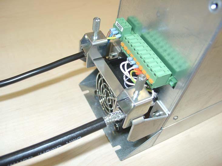
SFU-0303                                        Manual

Content
1        Introduction
2        Description and Features
3        Block Diagram
4        Technical Data
4.1      Version SSE
4.2      Version 19" and Desktop
5        Safety Precautions and Warnings
6        Connections, Interfaces and Pinout
6.1      Version SSE: Digital and Analogue Inputs X2
6.2      Version SSE: Digital und Analogue Outputs X3
6.3      Version SSE: Spindel Interface X4
6.4      Version SSE: Mains Connector, Spindle Connector
6.5      Version 19" and Desktop Version: Digital and Analogue In- and Outputs
6.6      Version 19" and Desktop Version Spindel Interface
6.7      Version 19" Mains Connector, Spindle Connector
6.8      Version Desktop: Mains Connector, Spindle Connector
6.9      Version SSE: RS232, RS485 X1
6.10     USB Connection
7       Functions, Setup, Operation
8.1      Front panel of SSE, Desktop and 19"Version
8.2      Converter Start and Stop
8.3      Status LED Display
8.4      LCD-Operating Panel
8.5      Setup of Rotational Speed
8.6      Safety Functions
8.7      Safe Power Stage Pulse Lock according EN 954-1 K3
8       Profibus
9       Setup with Windows-Software
10      Automatic Spindle Tuning
11      Examples for Connection
11.1     Mains and Spindle Connection
11.2     Logic and Wiring for Safety
12      EMC
13      Troubleshooting
14      General Hints
15      Warranty
16      Accessories
17      Mechanics and Dimension
17.1     SSE Version for cabinet mounting
17.2     19" Version
17.3     Desktop Version

    E                                              -2-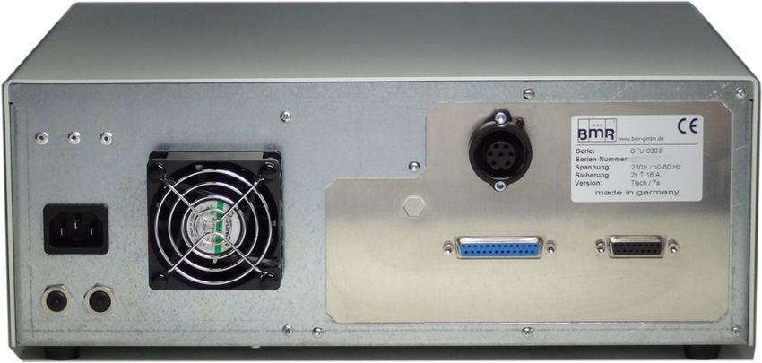
SFU-0303                                        Manual

1.    Introduction
     Due to its construction, the rotational speed of a 3-phase AC motor is directly dependent on the
     number of poles and the frequency of the network. In case of a 3PH 50Hz network and a 2-pole
     motor, the nominal speed would be 50 rps * 60 = 3000 rpm.
     In case of BLDC motors (brushless dc), the speed is directly dependent on the voltage applied.

     3-phase AC motors provide numerous benefits in industry, such as brushless operation, freedom
     from wear and tear, favourable capacity/weight ratio, high-speed capability, and much more.
     These motors can be used many different application areas, such as milling and grinding
     spindles, or with drilling machinery, for example.

     The advantages of SFU0303 compared to similar converters:

      -    Safe Power Stage Pulse inhibitor, authorized to current regulations EN 954_1 Categorie 3

      -    Maximum Power in industrial network up to 5kVA

      -    High efficiency by symmetrical PWM

      -    Real time vector control for sensorless operation

      -    Maximum Torque even at lowest rotational speeds

      -    High possible acceleration rates for short process times. For example 25.000rpm/sec with a
           2,2 KW Motor (with robotic applications)

      -    Pulse-Amplitude (PAM / =Block-Modus ) Control possible because of regulated intermediate
           voltage control (on option)

      -    Very slow rotational speeds (10rpm) possible for reaching tool changer positions.

      -    Very low current consumption because of real time power control

      -    Easy Integration into new and existing PLCs because of flexible I/O configuration

      -    Various interface options: Profibus, RS485, RS232, USB

      -    Easy reversing the direction of rotation by Software without loss of power.

      -    Autotuning function for spindle setup.

      -    Testrun with graphical documentation of voltages and currents of the spindle

      -    Up to 16 different spindle characteristics can be stored

      -    Very user-friendly debugging interface for setup control

      -    Start/Stop Interface for periodical tests or remote control

      -    Operating panel is detouchable and can be used as remote control together with an
           extension cable

      -    Designed for roughest use in industrial environment

      -    The housing of SSE is realized without ventilations slots and an outside mounted heatsink.
           preventing by this the intrusion of dirt and chips of tooling.

      -    Very compact case style makes easy cabinet mounting possible

 E                                                  -3-
SFU-0303                                        Manual

    -      Several case options for cabinet mounting (SSE) , 19" rack style and desktop, or special
           designs on request

    -      User friendly Screw-plug connector system for power-, spindle- and I/O connectors.

    -      Wide range of operating voltage 115V-230V

    -      Automatic deceleration of the spindle down to standstill in case of mains failiure by "Back
           Energy" Function

    -      Plain text display in amber color

    -      Very user friendly operation menu.

    -      USB connection and RS232 with specific adapter cable

    -      Full functional without operation panel in remote configuration

    -      Remote control hand-terminal available

    -      Controlled fan

    -      Datalogger-Function on option available in combination with PC software SFU-Terminal.
           Records of all relevant parameters of the converter in nearly infinite lengths are possible
           down onto the PC- hard disc.

E                                                 -4-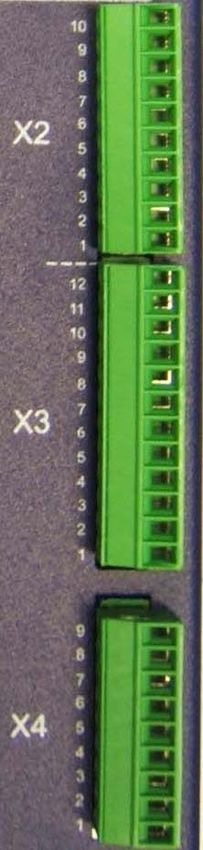
SFU-0303                                          Manual

2.        Description and Features

•       Operation of Asynchronous AC und BLDC Motors

•       The high frequency converter SFU-0303 makes possible rotational speeds
        with 2pole AC-Motors up to 500.000rpm and with BLDC-Motors up to 100.000rpm

•       High output power ( 3,6kV @ 230V / 2kVA @ 115V ) in compact style

•       The core of SFU-0303 is a Digital Signal Processor (DSP) which produces all output signals and
        collects all input signals

•       All parameters like current, voltage and frequency are collected in real time and are regulated by
        the implemented vector control depending on the load condition.

•       High precision sinusoidal output signals with low distortion factor realize very high accuracy in
        rotional behaviour.

•       Allows highest efficiency of the spindles at low and high frequencies

•       High operational safety: All operating conditions like acceleration, operation with nominal
        rotational speed, deceleration is monitored and critical conditions are intercepted.

•       Integrated braking resistance (brake chopper). Without brake chopper the deceleration times
        down to standstill can be longer.

•       Transparency: The user is always informed about the current status of the converter and the
        spindle on a plain text and detachable operating panel at the front panel.

•       Control: If needed, the converter can be controlled and parameterized manually with a pluggable
        operating unit.

•       Easy reversing the direction of rotation by Software without loss of power.

•       Individual adjustment to the current application and the connected spindle. Up to 16 different
        characteristics can be stored in the converter

        A variety of options for control and communication possibilities: For communication with
        peripheral devices, such as PC, PLC or CNC, there are 3 ports available:

•       Easy and flexible integration into existing equipments by free configuration of I/Os
        Control inputs:    2 Analog, 6 Digital
        Control Outputs:   2 Analog, 6 Digital (Relay)

•       Galvanic separation of all interfaces from each other and from mains / spindle potential

•       Short circuit proof

•       Comfortable Configuration und control with the help of a PC-Windows software "SFU-Terminal"

•       Cloning-Function with operating panel: Creating of clones of converters by individual read out
        of the SFU-parameters into the operation panel and download into another or multiple SFUs.

•       Automatic spindle calibration by autotuning function

    E                                                -5-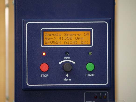
SFU-0303           Manual

3. Block diagram

                            picture 1

E                   -6-
SFU-0303                                      Manual

4. Technical data

4.1 Version SSE

Mains connection          115V, 60Hz, 1PH                             230V, 50Hz, 1PH
Output power              Max 2 kVA                                   Max 3,6 kVA
Motor connection          10-polig: PE,U,V,W, PTC, FP, SGND             pluggable screw clamps 4mm
                                                                                                     2

Output voltage            3* 110V                                 3* 220V
Output current / power    limited electronically
Over-current              maximal duration adjustable 0…20sec
Output frequency          AC: max 8,8kHz / 500.000 rpm       DC: max 100.000 rpm
Spindle characteristics   max. 16, stored internally
Spindle Sensor inputs     PTC, Speed sensor / Hall sensor, Logic:         9 pin pluggable screw clamps X4

Control inputs            2 Analog: 0-10V, separated galvanically:       10 pin pluggable screw clamps X2

Control inputs            6 Digital: 0-24V, separated galvanically:      10 pin pluggable screw clamps X2

Control outputs           2 Analog: 0-10V, separated galvanically        12 pin pluggable screw clamps X3

Control outputs           5 x Digital, free to be setup
                          1 x Digital reserved for power stage pulse inhibitor
                          outputs on Relays,         24VDC/1000mA, 125VAC/500mA
                          12 pin pluggable screw clamps X3

Interface                 - USB on operating panel                        USB-Mini

                          - RS232, RS485 am SFU                           9 pin DSub male

                          - Profibus on option as module, without operating panel
dimensions                see chap 17
Weight                    ca. 4 kg depending on option
Protection                IP20
Operating conditions      max ambient temperature 40°C, no humidity

    ATTENTION
    The operation of a spindle with a wrong characteristic may harm the spindle
    severely!
    Please ensure to have the proper characteristic selected always!

E                                                  -7-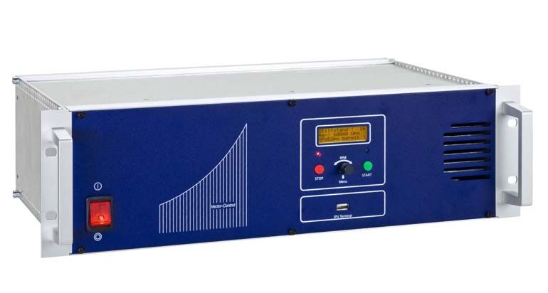
SFU-0303                                       Manual

4.2 Version 19" und Desktop

Mains connection          115V, 60Hz, 1PH                             230V, 50Hz, 1PH
Output power              Max 2 kVA                                   Max 3,6 kVA
Motor connection          9-polig: U,V,W, PTC, FP, SGND 2xPE,            screw clamps 4mm
                                                                                            2

Output voltage            3* 110V                                 3* 220V
Output current / power    limited electronically
Over-current              maximal duration adjustable 0…20sec
Output frequency          AC: max 8,8kHz / 500.000 rpm       DC: max 100.000 rpm
Spindle characteristics   max. 16, stored internally
Spindle Sensor inputs     PTC, Speed sensor / Hall sensor, Logic:               15pin D-Sub female

Control inputs            2 Analog: 0-10V, separated galvanically:               25pin D-Sub female

Control inputs            6 Digital: 0-24V, separated galvanically:              25pin D-Sub female

Control outputs           2 Analog: 0-10V, separated galvanically                25pin D-Sub female

Control outputs           6 Digital:    outputs on Relays,      24VDC/1000mA, 125VAC/500mA
                          25pin D-Sub female

Interface                 - USB on operating panel        used at the desktop, only
                          - RS232, RS485 am SFU                           9 pin DSub male

                          - Profibus on option as module, without operating panel
dimensions                see chap 17
Weight                    ca. 4 kg depending on option
Protection                IP20
Operating conditions      max ambient temperature 40°C, no humidity

    ATTENTION
    The operation of a spindle with a wrong characteristic may harm the spindle
    severely!
    Please ensure to have the proper characteristic selected always!

E                                                  -8-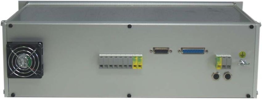
SFU-0303                                          Manual

5. Safety-Precautions and Warnings

•       This device produces dangerous electrical voltages and is used for the operation of dangerous
        moving mechanical parts. For this reason, only professionally trained and qualified personnel
        should be allowed to install and repair this device!

•       The operation with disconnected PE connection is not allowed.

•       Any maintenance or repair work to the device must only be carried out after the supply voltage
        has been disconnected!

•       Before the first commissioning can be carried out, it should be established that the motor is
        installed correctly and securely, to eliminate the possibility of uncontrolled movement of the
        motor.

•       Safety regulations that are valid for the country where the device is used, have to be adhered to
        where any work is carried out on the device.

•       Maintaining EMC (electromagnetic compatibility) limits is the responsibility of the manufacturer of
        the machine or device. The inputs and outputs on this device are fitted with filters, to increase the
        interference immunity and reduce emitted interference, making it possible to use this device in an
        industrial environment.

•       The EMC of a machine or device is affected by all connected components (motor spindle, length
        and type of cables, wiring, etc). Under certain conditions the use of additional filters can be
        necessary to maintain the current laws.

•       For the reasons listed above, installation and connection of the device should be carried out by
        qualified personnel only.

6. Connections, Interfaces and Pinouts
        For embedding into PLC and controls the SFU0303 has several input and outputs.
        These are realized as pluggable screw terminals and lead out at front and rear panel (depending
        on case option). All contacts are separated galvanically from high voltage carrying circuits.

        Operational parameters and outputs:
        The SFU-0303 covers all current important operational parameters and operating data.
        Up to 6 digital outputs can be used for signalling and up to 2 analogue values can be output to
        the analogue outputs (0-10V) .

        Remote Control and Outputs:
        6 digital inputs (24V) and 2 analogue inputs (0-10V) are available for remote control of the
        SFU-0303.

        These assignments can be configured freely. By using the optional Windows PC software "SFU-
        Terminal" the above mentioned assignments can be achieved easily, providing exceptional
        flexibility with each application.
        Each operating parameter can be assigned as a signal and each control signal can be allocated
        the required I/O pin. In addition, the logic level (high or low active) can be individually defined.
        The same assignment is also possible for the analogue measured data and control data at the
        analogue I/O pin.

        The standard allocations of operational parameters, their outputs, control signals and inputs, are
        listed in the following tables.

    E                                                 -9-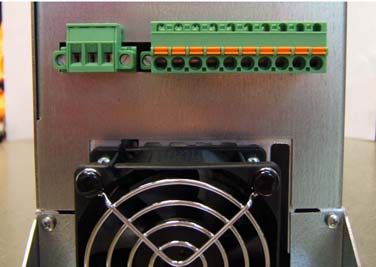
SFU-0303                                          Manual

6.1       Version SSE: Digital and Analogue Input X2 (10 pin Pluggable screw terminal)

                                                                             Picture 2

Pin        Description     Direction    Function / default Setting        switching state
  1        Digital In 1    Input        Start - Stop                      "0" Stop / "1" Start
  2        Digital In 2    Input        Power Stage Pulse Lock            "0" activated / "1" released
  3        Digital In 3    Input        Power stage Off                   "0" Aus / "1" On
  4        Digital In 4    Input        Locked / Emergency Stop           "0" released / "1" Emergency Stop
  5        Digital In 5    Input        Error reset                       "0" Errors have to be reset, with Hi
                                                                          level on this Input or with any Start
                                                                          signal
                                                                          "1" Errors are reset automatically
    6      Digital In 6    Input        Direction of rotation             "0" unchanged / "1" inverted
    7      Analog In 1     Input        Set value Rotational speed
                                               Scaling 10V min/max
    8      Analog In 2     Input        Set value Varioload
    9      GND             PWR          Ground reference for die
                                        Digital und Analog signals
    10     +24V/50mA       Output       Auxiliary voltage supply

The Default-settings of the functions for the outputs can be set up freely with the help of the PC-
Software SFU-Terminal.

•        Switching level digital inputs: Log"0" = 0…7V   / Log"1" = 18….24V       SPS Standard level

•        Analogue input range: 0…10V

•        The +24V at Pin 10 can be used as auxiliary voltage supply for Start / Stop signal with the help of
         a relay or for an electronic spindle interface.

    E                                                - 10 -
SFU-0303 Manual
6.2 Version SSE: Digital and Analogue Outputs X3 (12 pin Pluggable screw terminal )
Picture 3
Pin Description Direction Function / Message / default Setting
1 RelayCommon Common Rail Relay 1..5
2 Relay6 Normally closed Output Feedback signal for Power Stage Pulse Lock state
3 Relay5 Normally closed Output Excess temperature Converter or Spindle
4 Relay4 Normally closed Output Overload
5 Relay3 Normally closed Output Standstill Converter and Spindle
6 Relay2 Normally closed Output Spindle Ready
7 Relay2 Normally open Output
8 Relay1 Normally closed Output Converter Ready
9 Relay1 Normally open Output
10 Analog Out 1 Output
11 Analog Out 2 Output
12 Hall Sensor-Output Output modified signal square shape signal from encoder
The Default-settings of the functions for the outputs can be set up freely with the help of the PC-
Software SFU-Terminal.
An exception is the signal "Power Stage Pulse Lock", which is linked fix with Relay 6. According to the
switch state it will be output 0V / GND or +24V via 10kΩ referring to GND (X2.9) (-> 8.2 / 8.7)
+24V: Power Stage released 0V: Power Stage locked.
• The digital outputs (Relay1...5) are galvanically separated (500VIsolation).
DC: 24V / 1000mA AC: 125V / 500mA
• Output level Speed / Hall Sensor: 0-24V (24V Level)
E - 11 -SFU-0303 Manual
6.3 Spindle Interface X4 (9 pin Pluggable screw terminal)
Picture 4
Pin Description Direction Function / default Setting
1 +12V/50mA Output Auxiliary voltage supply
2 Spindle GND Ground reference
3 NC Not connected
4 Speed sensor input Input Input for 2/3-wire speed sensors / Hall sensor from spindle
5 PTC Input Temperature signal from Spindle / KTY as Option
6 Bit 4 Input automatic Spindle detection
7 Bit 3 Input automatic Spindle detection
8 Bit 2 Input automatic Spindle detection
9 Bit 1 Input automatic Spindle detection
The Default-settings of the functions for the outputs can be set up freely with the help of the PC-
Software SFU-Terminal. The inputs of the encoder and the PTC are fix wired.
• The spindle interface is separated with optocouplers from all other signals. It can be used for an
automatic spindle detection, if activated. The logic levels are low-active by default: "HI" > PIN
connected with Spindle-GND, "LO" > PIN open. In the menu "Digital Inputs" this can be changed.
• The input "PTC" is provided for detection of excess temperature of the spindle. If the resistance
between PTC and GND is > 600Ω, the error message ‘Excess temperature Spindle’ is set and a
safety shut down is carried out after expiring of the delay time.
• On option a temperature detection for KTY is possible. This requires a HW modification.
• The input 4 for the speed sensor works in the range of +/- 1V with a common mode range of
0..10V.
• The +12V at Pin 1 can be used as auxiliary voltage supply
E - 12 -SFU-0303 Manual
6.4 Mains and Spindle connection at SSE
+VFP
SGN Pin Name Direction Function
D 1 +VFP Output Auxiliary voltage supply for active speed sensor 12V/50mA
FP
2 SGND Ground reference for signals FP, PTC
PTC 3 FP Input Input for 2/3-wire speed sensors / Hall sensor
4 PTC Input PTC Temperature signal from Spindle / on option KTY
W 5 W Output Spindle Phase W
V 6 V Output Spindle Phase V
7 U Output Spindle Phase U
U 8 Rext Output External Brake resistor / Chopper Resistor
Rext 9 +ZU Output Intermediate voltage (! Attention, High Tension !)
10 PE Connection for protective earth of the spindle. ! Safety !
+ZU
PE
Name Function
PE
PE Protective Earth ! Safety !
N N Null
L L Phase
Picture 5
The device has no internal fusing. It has to be fused externally
Please ensure, that PE protective earth is connected at the mains side. The
device must not be operated without properly connected PE!
Please ensure, that PE protective earth is connected at the spindle side as well
as at the mains side.
Control wires, Mains cables and spindle cables should be installed separately.
For wiring, the use of shielded cables is recommended.
View at screw terminals at version SSE
Picture 6
E - 13 -SFU-0303 Manual
6.5 Version 19" und Desktop:
I/O Interface - Digital and Analogue In- and Outputs (D-Sub 25pin female)
Pin Description Direction Function / Message / default Setting
1 Relay Common Common Rail for Relay contacts
14 Relay Common
2 Relay 1 Normally Closed Output
15 Relay 2 Normally Closed Output
3 Relay 3 Normally Closed Output
16 Relay 4 Normally Closed Output
4 Relay 5 Normally Closed Output
17 Relay 6 Normally Closed Output Feedback signal for Power Stage Pulse Lock state
5 Relay 1 Normally Open Output
18 +24V/50mA
6 +24V/50mA
19 GND
7 GND
20 Relay 2 Normally Open Output
8 Hall Sensor Output Modified signal from speed sensor
21 Digital In 2 Input Output Stage Pulse Blocking
9 Digital In 6 Input
22 Digital In 5 Input
10 Digital In 4 Input
23 Digital In 3 Input
11 Digital In 1 Input
24 Analog In 1 Input
12 Analog In 2 Input
25 Analog Out 1 Output
13 Analog Out 2 Output
The Default-settings of the functions for the outputs can be set up freely with the help of the PC-
Software SFU-Terminal.
An exception is the signal "Power Stage Pulse Lock", which is linked fix with Relay 6. According to the
switch state it will be output 0V / GND or +24V via 10kΩ referring to GND (7, 19) (-> 8.2 / 8.7)
+24V: Power Stage released 0V: Power Stage locked.
• The digital outputs (Relay1...5) are galvanically separated (500VIsolation).
DC: 24V / 1000mA AC: 125V / 500mA
• Analogue input range 0…10V
• Output level Speed / Hall Sensor: 0-24V (24V Level)
• +24V at Pin6, 18 may be used as auxillary power supply for e.g. an electronic spindle interface
E - 14 -SFU-0303 Manual
6.6 Version 19" und Desktop: Spindel Interface (D-Sub 25pin female)
Pin Name Direction Function / default Setting
1 NC
9 +12V/50mA Auxiliary voltage supply
2 GND
10 GND
3 Bit 0 Input automatic Spindle detection
11 Bit 0 Input automatic Spindle detection
4 Bit 1 Input automatic Spindle detection
12 Bit 1 Input automatic Spindle detection
5 Bit 2 Input automatic Spindle detection
13 Bit 2 Input automatic Spindle detection
6 Bit 3 Input automatic Spindle detection
14 Bit 3 Input automatic Spindle detection
7 PTC Input Temperature signal from spindle
15 PTC Input Temperature signal from spindle
8 Hall Sensor Input Speed signal from speed sensor from spindle
The Default-settings of the functions for the outputs can be set up freely with the help of the PC-
Software SFU-Terminal. The inputs of the encoder and the PTC are fix wired.
• The spindle interface is separated with optocouplers from all other signals. It can be used for an
automatic spindle detection, if activated. The logic levels are low-active by default: "HI" > PIN
connected with Spindle-GND, "LO" > PIN open. In the menu "Digital Inputs" this can be changed.
• The input "PTC" is provided for detection of excess temperature of the spindle. If the resistance
between PTC and GND is > 600Ω, the error message ‘Excess temperature Spindle’ is set and a
safety shut down is carried out after expiring of the delay time.
• On option a temperature detection for KTY is possible. This requires a HW modification.
• The input 4 for the speed sensor works in the range of +/- 1V with a common mode range of
0..10V.
• The +12V at Pin 1 can be used as auxiliary voltage supply
E - 15 -SFU-0303 Manual
6.7 19" Version: Mains and Spindle connection
Spindle Interface I/O Interface
Spindle connection Mains Connection
Sicherungsautoma
Automatic Fuses
Back side SFU0303-19" with spindle connector clamp terminal Picture 7
Spindle Connector - 9pin clamp terminal
Pin Name Direction Function
1 +VFP Output Auxiliary voltage supply for active speed sensors 12V/50mA
2 SGND Ground for signals FP, PTC
3 FP Input Input for two/three wire-speed sensors
4 PTC Input temperature signal of spindle or as option KTY
5 W Output Spindle phase W
6 V Output Spindle phase V
7 U Output Spindle phase U
PE PE
Connection for protective earth of the spindle. ! Safety !
PE PE
Mains connection - 9pin clamp terminal
Name Function
PE protective earth ! Safety !
N Neutral
L Phase
Please ensure, that PE protective earth is connected at the mains side. The device must
not be operated without properly connected PE!
Please ensure, that PE protective earth is connected at the spindle side as well as at the
mains side.
Control wires, Mains cables and spindle cables should be installed separately.
For wiring, the use of shielded cables is recommended.
E - 16 -SFU-0303 Manual
6.8 Desktop Version: Mains and Spindle connection
The connection with mains network is carried out with an IEC connector
The device is equipped with a Thermo-Automatic Fuse for each prong. They can be reset after tripping
by pressing down the button
The spindle connection is realized on custom order and can be realized accordingly
IEC Mains connection Spindle connection
Automatic Fuse
Sicherungsau
I/O Interface Spindle Interface
Backside SFU0303-Desktop equipped with a 7pin circular spindle connection Picture 8
Spindle Connection 7pol. female Binder Series 693 or Amphenol C16-1
6 SGND Signal GND for PTC- and FP-Signal
5 W Spindle Phase 3
4 FP for speedsensor of the spindle
7 PE Protective Earth
3 V Spindle Phase 2
2 PTC for temperature sensor of the spindle
1 U Spindle Phase 1
Control wires, Mains cables and spindle cables should be installed separately.
For wiring, the use of shielded cables is recommended.
E - 17 -SFU-0303 Manual
6.9 RS232, RS485 - X1 at Version SSE
At SSE devices the connection X1 INTERFACE is provided for the operating panel. A RS232 and a
RS485 interface is wired to this connector. The 19" and desktop versions have built-in operating
panels which are not detachable.
With disconnected operating panel a connection to a PC or any control can be established with a
specific BMR cable. A standard cable wont work or may harm the device.
The operating panel is fixed with 2,5mm Allen screw to the SFU0303. After unfixing the operating
panel can be removed. Additionally it can be used as a remote control in conjunction with a 1:1 cable.
Pin Function
1 Release
2 NC
3 A-RS485
4 RxD-RS232
5 GND
6 +5V-RS
7 NC
8 B-RS485
9 TxD-RS232
Picture 9
6.10 USB-Connection
For easy connection and communication, the device is equipped with a USB interface. At the version
SSE it is located at the bottom side as USB Mini AB. At the 19" and Desktop devices, it is found at the
front panel directly below the display.
USB
Picture 10
E - 18 -SFU-0303 Manual
7. Functions, Commissioning, Operation
7.1 Front panel SSE, Desktop and 19" Version
picture 11 front panel SSE
picture 12 front panel Desktop
picture 13 front panel 19" version
E - 19 -SFU-0303 Manual
7.2 Starting of the Converter and Power Stage Pulse Lock
Spindle Characteristics
All converters of BMR need an information about the basic data of the spindle, such as maximum
voltage, current, rotational speed, and many more. These are stored in so called "spindle
characteristics". A BMR spindle characteristic has 16 setpoints within the range of the rotational
speed. At every point data of voltage, current, load scaling, acceleration and deceleration ramp and
many more data can be defined and this for idle load as well as for full load. And there are in total 16
places for different characteristics. The spindle characteristics are the key for any spindle and give a
possibility to control the running behavior at every load condition.
In advance of start of a spindle first, it has to be ensured, that the proper characteristic is selected and
activated. This is generally the case if the device is delivered together with a spindle and the required
setup is done. If the converter and spindle are delivered separately, the proper spindle characteristic
has to be loaded into the converter first. This can be achieved with the free setup software SFU-
Terminal, easily.
In case of being unsure, characteristics for most common spindles are available at BMR.
Start and Stop
There are different possibilities for starting and stopping SFU0303, due to many different
requirements, as follows below:
Generally, a STOP can be triggered by the source of START, with the exception of an Emergency
Stop, activated Intermediate voltage lock or any other safety function.
- Start button at operating panel, Rotational speed with encoder potentiometer
- Pure serial control with commands via USB / RS232 / RS485 / Profibus interface
- Digital input in combination with an activated analogue input for control of rotational speed.
In case of not being activated, the rotational speed is setup with encoder poti on operating
panel or via serial commands.
Power Stage Pulse Lock
Precondition for proper starting is a released power stage pulse lock (Bridge X2.2 – X2.10), as well as
a proper characteristic for the connected spindle.
The converter of the 0303 series are equipped with an safety power stage pulse locking circuit which
has to be wired properly for operation. For activating the power stage a voltage with carrying a high
signal should be applied to digital input 2 / PIN2. The voltage can be fed from PIN10. So, easy as
possible simply a bridge between PIN2 and PIN10 will do this. The feedback signal about the status is
displayed on the operating panel, if equipped, on LED6 and on relay output 6 at connector X3.
Attention! Without this connection the converter cannot be started.
The power stage pulse lock is realized according the requirements of EN954-1 Category 3 for safe
stop of drives. (-> Chap 8.7) +24V: Power Stage released 0V: Power Stage locked.
Status
The current status of the converter is displayed on the status LED display and with mounted operating
panel the status is displayed in plaintext on the LCD-display, additionally.
E - 20 -SFU-0303 Manual
7.3 Status LED Display
1 2 3
Run / SFU is running Emergency Stop
Overload
Intermediate voltage
lock
Excess temperature spindle
Spindle not ready
4 5 6 SFU Ready
Picture 14
Typical displays. Other combinations are possible due to status.
Ready + Standstill Converter OK,
Converter and Spindle and Spindle is running
ready Overload
Converter OK, Emergency Stop
Spindel running and/or Locked
Spindle running
Excess temperature at Power Stage Pulse Lock active
Converter
Converter ready
Spindle running,
Excess temperature at Earth fault
Spindle
Picture 15
A Start can be initiated with display "Converter and Spindle". There are different means for solving
errors which are listed in Chap "Troubleshooting"
The most probable reason for problems is a not properly wired input for "Emergency Stop" or
"Intermediate Lock". In this case it is recommended to check the setting in the menu "Digital Inputs" in
SFU-Terminal
E - 21 -SFU-0303 Manual
7.4 LCD-Operating Panel
Line1:
- Info
- Nr. of the selected characteristic
Line 2:
- Display of direction of rotation
- Current rotational speed of SFU
or duty value preset "rpm"
- Current Real-Speed "rpmSP"
Line 3:
- Load display in %,
- Status display
Red LED
Green LED
Stop Button Rotary Encoder as potentiometer Picture 16
Start Button
and button
Dialing for paging in the menu
Pushing for selection
Operating Elements:
Start-Button
For Starting the Spindle
Stop-Button
For Stop of Spindle or ending the Menu function
Encoder Potentiometer und Menu-Button with multifunction
During standstill and run mode the duty value for speed can be setup by dialing
Short pushing during run mode switches on the debug mode.
Long pushing during standstill opens the setup menu
Dialing selects the menu item and
Short pushing selects the function.
Automatic ending of the menu after 10sec without manipulation or
short pushing of the Stop-Button
LED green
for indication of Ready for Operation or of Run mode und Spindle is spinning
LED red
for indication of Standstill or of Stop mode or Error
E - 22 -SFU-0303 Manual
Start and Stop
In the simplest case, a connected and appropriately set up spindle can be started by pressing the
Start-Button. The desired speed can be adjusted by dialing with the rotary encoder either as
preset value during standstill or in Run mode. The preconditions for a correct Start can be looked
up under 7 and 7.1 .
Any error or malfunction is displayed as plain text
All relevant system messages on rotational speed, load or problems are displayed on the LCD
display
The current power output is displayed in the lower part as analogue load bar as % and absolute.
An overload condition will be displayed as well.
The pre selected and current speed, the selected characteristic are displayed
Attention:
The operation of a spindle with an incorrect spindle characteristic may harm the
spindle severely!
Please ensure that the correct characteristic is selected
If several spindles are operated simultaneously, it has to be ensured that they are of
the same type and that a specific characteristic is selected.
Otherwise this may harm one or more spindles or the converter severely!
E - 23 -SFU-0303 Manual
Setup-Menu:
To enter the menu, the Menu-Button in the rotary encoder should be kept pressed for more than 1sec.
After that and releasing the button the following menu items can be selected by dialing.
• D irec tio n of Ro ta tion CW/CCW
• Se lec tio n of sp in dl e ch arac teris tic Characteristics 1..16 are displayed
• De bug Mo de Display of Mains voltage, current and spindle voltage for 30sec
• F ir mwar e Ve rsi on Current Version Nr. at line2 for 5sec
• L ang uag e Selection of display language: German, English, French
• Co n tras t Adjusting the contrast
• Re ad Co n fig Read out the SFU project data into the operating-panel (Æ Cloning )
• Wr i te Co n fig Download of stored project data into the SFU (Æ Cloning )
• ESC Quit menu
With the rotary encoder a menu item can be selected which will flash if it is active.
By pushing the Menu-Button, the current item or the final entry is selected.
With ESC or pressing the Stop-Button or after approx. 10sec without activity the menu is quit without
changes. The display returns to standard operating mode.
The adjustment of direction of rotation and the selection of the characteristic are possible during
standstill, only.
In case of activating the menu during run mode, the spindle will be stopped after 5sec. for safety
reasons.
Attention: Selecting the function Wr i te Co n fi g the currently stored project data of the SFU will be
overwritten without warning. By this a cloning of several SFUs can be carried out easily. Please verify,
if this is really intended and if there are loaded proper project data into the memory by a previously
Re ad Co n fig operation.
StandstiIl ! 3
Characteristic 3 is selected
CWÆ 25000 rpm
preset speed 25.000rpm
Conv&Spin ready !
Standstill
3
Converter is accelerating Outp. 7830 rpm
Power output 67%
▐▐▐▐▐▐ _ _ _ _ _ 6 7%
Duty speed OK 3
Spindle is running at set value duty speed CWÆ 25000 rpm
Power output 20% ▐▐_ _ _ _ _ _ _ _ _ 2 0 %
Overload 3
Any error is displayed in plaintext in line 1
Outp. 25000 rpm
C o n v. n o t r e a d y !
E - 24 -SFU-0303 Manual
Adjustments:
Rotational speed:
dialing right or left with rotary encoder pot. Current value is displayed steadily. This can be the setup
value before start or the current value during run.
Start/Stop:
with Start/Stop button. If the operating unit is removed during the start process the converter
automatically turns into stop condition.
Debug Mode
During operation the debug mode can be entered by shortly pressing on the Menu-Button. It will be
displayed the rectified mains voltage, spindle current and spindle voltage.
After 30sec of inactivity it will be returned to the standard mode, automatically.
With an additional pressing the debug mode is ended and it will be returned to the normal mode, but
with displaying of the real spindle speed in place of the set value of the converter speed. This is
indicated with "rpmSP". This persists permanently unless a further pressing of Menu-Button, which will
return to the display of set value of the converter speed ("rpm")
Cloning
With the menu-item "Read Config" the configuration of a converter can be read out into and stored
within the non volatile EEProm memory of the operating panel. By swapping this panel to another
converter this configuration can be copied into this converter with the menu item "Write Config". This is
a very easy method to copy one configuration to many other converters (cloning) without any PC. But
it has to be taken care that, this is not carried out without having read out any configuration before,
because transferring an empty or corrupted configuration into the converter, will cause severe
problems!
E - 25 -SFU-0303 Manual
The following error displays are possible:
Display Error
• Pu lse block ing ! Power stage lock active
• Overload Stop Overload stop!
• Overtemp conv. Excess Temperature Converter
• Overtemp spindle Excess Temperature Spindle
• Overvoltage trip Mains voltage too high
• Undrvoltage trip Mains voltage too low
• Undervolt.stop Mains voltage too low
• Pwr stage off! output stage switched off
• Emgcy stp active Emergency input engaged
• No spindle ! Without spindle or cable defect
• RS232 Error ! Timeout serial interface
• Diagram Error! Invalid characteristic
• Enc oder Er ro r ! Error with speed sensor / hall sensor
• Back engy trip Error Power Stage switch off because of
deceleration ramp to high
• GND fault ! Error PE is connected with a spindle line or
converter is defective
7.5 Adjustment or rotational speed
The preset of the rotational speed can be achieved by two ways:
• manually preset with menu keys
For this, the Option-Button 0 in the line Duty speed in the grey field in the menu "Analogue-
Inputs" of SFU Terminal Software has to be activated. By this all analogue inputs were switched
to inactive and no analogue signal is selected for Start.
The duty value for rotational speed is displayed at the LCD-Display and can be adjusted with the
rotary encoder. The speed of change is dependent on the speed of dialing. The rotational speed
can altered during operation, also.
• preselection with a voltage applied to the analogue input SetValue Rotational speed
For this, an analogue input has to be assigned to this function, which can be done in SFU
Terminal Software in the menu "Analogue-Inputs". Additionally it has to be selected a scaling for
the analogue voltage in the listbox field at left. 3 scalings are possible: 1V/10.000rpm or
1V/1.000rpm or 0-10V min/max).
The value of the rotational speed according the scaling is displayed on the LCD-display and can
be altered as wanted.
An input voltage of 0V leads to Standstill and a voltage > min voltage will make the spindle start
up to the speed according to the current scaling.
A scaling 1V/10.000 and a voltage of 4V will cause a speed of 40.000 rpm.
All settings made in SFU-Terminal have to downloaded into the SFU before they are valid with
the button Write only I/O (F6) .
E - 26 -SFU-0303 Manual
7.6 Safety functions
The below mentioned adjustments refer to settings made in SFU-Terminal
The following incidents lead to a controlled braking and decelerating to standstill of the spindle
according to its acceleration times defined in the spindle characteristic.
• Stop because of excess temperature at the spindle, in case this function is activated and if its
corresponding delay time is exceeded, which can be adjusted in the menu "Delays..excess
temperature spindle"
In the "Spindle characteristic" this function can be activated with the Check-Button Temp. sensor
and according delay time can be setup in the menu "Delays"
• Stop because of excess temperature of the converter, in case this function is activated and if
its corresponding delay time is exceeded, which can be adjusted in the menu "Delays..excess
temperature converter"
• Stop because of overload and if its corresponding delay time is exceeded, which can be adjusted
in the menu "Delays..overload" The limit values for overload are determined in the spindle
characteristic. Generally for S1 operation the current value will be 100% and overload condition is
about 10% more and for S6 operation about 30% more. The default delay value is 20sec.
• Immediate stop because of exceeding the maximum admissible current of the converter
• Emergency Stop because of a valid signal at input Emergency Stop setup in menu "digital
inputs"
The following incidents lead to a shut off of the output stage. the spindle will not be braked and will
decelerated by its internal losses and friction. This can take quite a long time until standstill depending
on its rotary mass. For a safe detection of standstill a speed sensor would be recommended.
• Stop because of short circuit at spindle connector. The value is defined by internal limits.
• Stop because of signal at digital input Power Stage Off setup in menu "digital inputs"
A restart can only be achieved with a systematic Stop/Start-Sequence or with a valid signal at the
input "Error Reset". This can be setup in the menu "digital inputs" the power stage will be
activated again after 4 sec.
E - 27 -SFU-0303 Manual
7.7 Safe Power Stage Pulse Lock according EN 954-1 K3
The SFU0303 is equipped with a safe power stage pulse inhibitor circuit according Category 3.
This requires that an independent circuit besides the microprocessor circuit grants that the power
stage can be activated with an external signal, only. This is realized in the SFU0303.
The feedback is realized via Relay 6 SSE: (X3.2) , Desktop/19": (Dsub25.17)
According to the switch state it will be output 0V / GND or +24V via 10kΩ referring to SSE: (X2.9) ,
Desktop/19": (Dsub25.7,19) (-> 8.2)
+24V: Power Stage released 0V: Power Stage locked.
Picture 15 shows the basic principle for wiring with a PLC
Activating and releasing Power Stage Pulse Lock
State of Power Stage Lock is active: the converter is in a safe
state, Level at X3.2 for this stage is "low"
For testing purpose a bridge between X2.2 and X2.10 can be wired. Herewith the converter is activated for running, but this
must not be realize in applications which have to be certified according EN954-1!
Safe Power Stage Pulse Lock according EN 954-1 K3
Picture 17
E - 28 -SFU-0303 Manual
8. Profibus
For operating the SFU0303 within a profibus dp fieldbus a separate module is available as option. This
ensures an implementation according standards.
It will be mounted instead of the operating panel on interface X1.
Picture 18
The setup of the address is carried out with RS232, a specific connection cable and SFU-
Terminal.
The require files including the description of the commands and gsd-files are available on the
BMR website.
It has the same basic setup possibilities as with the standard operating panel.
E - 29 -SFU-0303 Manual
9. Setup, Parameterization and Configuration with SFU-Terminal
The software SFU-Terminal is a tool for the configuration of BMR frequency converters of the
series SFU0102….SFU0601. Moreover it offers the possibility to read out system data and to
modify them. To achieve this, the following steps should be taken:
1. Install the setup file according the installation software.
2. Power On the converter and establish the connection via USB / RS232.
3. Launch the program SFUTerminal.EXE
4. If the connection is established correctly, the program detects the converter automatically. In
this case, the firmware of the converter is displayed in SFU-Terminal.
5. By click on Start it will at first carried out an upload of all parameters of the converter, a so
called "project".
6. The program can be started "Offline" without a connected converter, too. The required
converter can be selected manually from a list.
Picture 19
More information in Help
E - 30 -SFU-0303 Manual
10. Automatic Spindle Tuning and Calibration (Autotuning)
If a motor without having a spindle characteristic has to operated with SFU0303, it can be created very
simple with the help of this tool in SFU-Terminal. The spindle is connected with the converter and the
converter is connected with a PC and in the menu "Tools" the tool "Automatic Diagram" is started.
Picture 20
Simply the basic data of the spindle have to be input. Important is to mention the nominal voltage
according to the proper speed value. The reason for this is, that AC-motors can be operated in a
weakened field mode, also, which makes possible a higher rotational speed but with reduced power.
E - 31 -SFU-0303 Manual
Example 1, normal adjustment:
A 2-pole motor with a maximum rotational speed of 30.000rpm needs at this point a nominal voltage of
220V at a current of 5A .
Picture 21
Example 2, weakened field, field suppression:
A 2-pole motor with a maximum rotational speed of 30.000rpm needs at 20.000rpm a nominal voltage
of 220V at a current of 5A . But the voltage cannot be raised further, so the desired speed can be
achieved but with reduced power.
Picture 22
The current limit, in this case 8A, indicates the S6 mode, where it is 5A as the nominal current for the
S1 mode.
The acceleration values (Ramp up/down) should be setup to be 12000rpm/sec. It has to be ensured
that the shaft can rotate freely.
Start the automatic and save the characteristic after having finished the procedure. Download it into
the converter.
Caution:
If using this autotuning, damages at spindles or the converter are part of warranty,
due to possible wrong input values.
E - 32 -SFU-0303 Manual
11. Examples of Connection
11.1 Mains and Spindle connection
Mains
Brake Chopper
L1 N PE PE +ZU Rext U V W PTC Fp SGND +VFp
Picture 23
E - 33 -SFU-0303 Manual
11.2 Example for Logic and Wiring for Safety Circuit
Direction of rotation
Error reset
Emergcy Lock
Power stage off
Power stage lock
Start
Overload
Feedback signal Power Stage Pulse Lock
Excess Temperature Conv, Spindle
Standstill Conv. / Spindle
Spindle Ready
Converter Ready
Picture 24
The spindle interface X4 isn't wired, because the use is depending strongly on the configuration
of the spindle and the according its specific characteristic.
This interface in combination with an automatic spindle detection should be used only
after consultation with BMR.
By assigning the four address lines the spindle characteristic can be selected by an PLC or
external switches, in case it has been enabled
E - 34 -SFU-0303 Manual
The digital wiring can even be achieved with outputs of logic circuits, with a High Out level > 20V.
The picture shows a configuration with passive switches in combination with the auxiliary voltage
of the converter.
For stabilizing the reference analogue voltage for the duty speed a voltage regulator 7810 is
used. In combination with a PLC generally a D/A-converter with 10V output level is used
The outputs are executed in such a way that the logic levels 0V and +24V are generated by the
galvanically separated relays. For any other arrangement, the relay contacts can be wired and
used freely. In the arrangement shown above, the logic level is assigned to the GND of the
converter. The outputs shown in the diagram can be used directly as feed into a PLC.
Description of the behaviour during Start with released analogue input: Scaling:0-10V/MinMax
Enabling via input "digital start" – the spindle starts as soon as the level at the analogue input
"duty speed" is higher than the minimum rotational speed limit being setup in spindle
characteristic. It will stop, as soon as either "digital start" is low or the level at analogue input
"duty speed" is below the minimum rotational speed limit.
In case of applying 10V to "analogue input "duty speed" and 16V to "digital start", the spindle will
accelerate up to maximum speed.
12. EMC
This device was developed for use in industrial environments. For trouble-free operation and to
reduce emitted interference, the following should be observed during wiring of the equipment:
• The EMC of a machine or device is affected by all connected components (motor spindle, length
and type of cables, wiring, etc..). Under certain circumstances the use of additional filters may be
necessary to maintain the current laws.
• The earth and shield connections of all those devices used in interconnection with the frequency
converter should be as short as possible and have as large a cross-section as possible.
• Control units (PLC, CNC, IPC, ...) used in interconnection with the frequency converter should be
connected to a common earth terminal bar.
• For mechanical installation, use serrated lock washers to guarantee good electrical contact with
the housing.
• All connections both to and from the frequency converter should be via shielded cable. Earth
shield should be connected on both sides.
• The shield must be completely connected to PE (protective earth).
• Power lines, motor lines and control lines should be laid separately and have to be isolated from
each other. Where crossings cannot be avoided, it should be executed at 90° to each other.
• The control cable should be laid as far away as possible from the power cables.
E - 35 -SFU-0303 Manual
13. Troubleshooting
Error Description Cause Fixing
After power on the Input "Emergency Stop" is not +24V Signal at this input
converter indicates properly or not wired at all.
Not Ready and Error
The converter is at excess > Let the converter cool down
temperature > Check, if the fan is working properly or
maintain that air flow around the heatsink is
sufficient
> Slow down the tooling process
Pulse inhibitor circuit is engaged, at > For disengaging wire +24V to the
devices with such a circuit (SFU0303) appropriate Pin
> Wire a bridge between X2.1 - X2.10
(SFU0303)
A spindle diagram which is not valid is Change spindle characteristic with the help
selected of the front panel keys or with SFU-Terminal
Short circuit detection of the out put > Check, if the spindle is blocked
has tripped
> Check, if there is a short circuit within the
spindle
> Check, if there is a Ground fault (at least
one prong of the spindle cable is connected
with PE)
> Check, if there is a short circuit within the
spindle cable
Error Description Cause Fixing
After power on the No spindle connected Connect spindle
converter indicates Not
Ready and Error
No temperature sensor present within Disable in spindle characteristic menu in
and the spindle SFU-Terminal the Temperature Sensor
button
the evaluation of the
temperature sensor is
activated in the spindle Temperature sensor of the spindle > Change spindle
characteristic defective
> Disable in spindle characteristic menu in
SFU-Terminal the Temperature Sensor
button
E - 36 -SFU-0303 Manual
Error Description Cause Fixing
In case of connecting the Incorrect connection cable or wiring > Check cable for proper Pinout.
converter with a PC or fault
after launching the SW > Verify at USB cables that it's length is not
SFU-Terminal the longer than 2m
Converter is not
detected and not > Try to use original BMR cables, only.
recognized
In case of using RS232 > Use the USB-Interface at the PC together
with a USB-RS232 converter.
> For use with SFU 0303 a specific RS232
cable is required
In case of using a USB-RS232 install driver
converter the USB-driver is not
installed correctly.
unsure Restart SFU-Terminal
Start with push buttons Start button deactivated Enable Start button by un-checking the
not possible checkbox "Block Start Button"
Spindle does not start, An input is assigned with the function > For unlocking, a signal of "HI" / +24V is
in spite of a valid signal Emergency Stop and configured as required at this input
for Start "Low Active".
> Deactivate this function or setup as "High
> This is default state on delivery Active"
The evaluation of the temperature > Connect the temp sensor wires with the
sensor is activated in the spindle SFU .
characteristic, but it is not connected
or a sensor isn't implemented within > un-check the button "Temp Sensor" in the
the spindle spindle characteristic in SFU-Terminal
-> in this case Error is indicated,
additionally
The spindle test is engaged > Check cable and connections for proper
wiring or short circuit
> Check spindle
E - 37 -SFU-0303 Manual
Error Description Cause Fixing
Spindle does not start, Spindle cable and spindle are OK, > Select correct spindle characteristic
in spite of a valid signal and the spindle test is activated
for Start > In the spindle characteristic the value of
> Spindle cable is too long the start voltage has to be increased.
-> contact BMR
With activated spindle test, a test
current is send via spindle cable to the
spindle by applying a voltage at output
lines. In case that this current is too
low, or a wrong spindle characteristic
selected, it does not match to the
reference values and the spindle test
fails.
The error message Spindle is at excess temperature Let it cool down
Spindle not ready is > Check, if the characteristic matches with
indicated. the spindle
PTC in the spindle is defective change spindle
The PTC-wires within the spindle exchange cable or fix the connection
cable are defective
Start via Digital Input is Start via Analogue input is activated. Deactivate Start via analogue input.
not possible -> Manual: "Analogue Inputs"
and activate Digital Start
Set value for duty speed is too low Increase Analogue value for duty value.
> A spindle start is carried out after reaching
the required minimum voltage according to
the scaling, only
It is displayed Error Char The selected spindle characteristic at > Select matching characteristic with the
xx or E xx memory place xx is wrong, invalid or help of the buttons at the front panel or with
corrupted. SFU-Terminal
> Contact BMR
E - 38 -SFU-0303 Manual
Error Description Cause Fixing
With activated speed Loose connection in spindle, spindle > Check spindle cable and exchange
sensor: cable or at the connectors potentially
> Check connectors
The spindle runs properly,
but sometimes there
appears the message Disturbances on the signal or the > Exchange spindle cable
Encoder Error. signal amplitude is too low > for verification test exchange spindle
> sensor wires in spindle cable are
not shielded
Error Without Spindle, Spindle cable is defective > Check the 3 spindle phase wires
Cable is displayed
Spindle cable too long > Check, if the proper characteristic is
selected.
With activated spindle test, a test
current is send via spindle cable to the > Increase value for start voltage in the
spindle by applying a voltage at output spindle characteristic
lines. In case that this current is too -> contact BMR
low, or a wrong spindle characteristic
selected, it does not match to the > Deactivate function "Spindle test"
reference values and the spindle test
fails.
E - 39 -SFU-0303 Manual
14. General Hints
Our frequency converters are highly valuable precision devices. Please take care of them with the
necessary attention, to preserve their high precision, high power ability, and long lifetime.
These devices leave our company only after a quality test and a full load check have been carried
out. Before mounting and use, please read the attached manual carefully and pay attention to the
points listed below.
• Before first activation of the device, verify, if it id in a faultless condition. If it was damaged
during shipping and transportation it must not be switched on.
• During installation the safety regulations have to be observed.
• Before the device is turned on for the first time, it should be verified, that the connected parts
cannot carry out uncontrolled movements.
• The frequency converter must not be operated close to heating devices or magnets or devices
generating strong magnetic fields.
• The maximum permissible ambient temperature of this device is from +41 °F till +104 °F.
• Sufficient air circulation around the converter should be ensured
• Fluids should be prevented from intruding into the housing. If it seems to be happened, the
converter has to be switched off immediately.
• The relative humidity must not exceed 90% (not condensed).
• The ambient air must not use aggressive, flammable or electrically conductive substances and
should be as free of dust as possible.
• All repairs and maintenance on the converter and the relating accessories must be carried out
by skilled personal and with powered off, only. To ensure this, the mains plug should be pulled
out. In doing this, both the terms of regulations for preventing accidents and the general and
national rules for mounting and safety have to be applied.
• The device must not be operated without properly connected PE connection and it has to be
verified that the mains connector is fixed with screws, if detachable.
Our common hints can give only a rough guideline because it is not possible for BMR GmbH to
cover all specific situations. The compliance with limits of EMC demanded by law is the
responsibility of the manufacturer of the unit or the machine. By doing controls and tests in our
laboratory or in delegated test-laboratories, BMR takes care, that our products comply with the
corresponding standards, in case they are installed appropriately.
E - 40 -SFU-0303 Manual
15. Warranty
With exclusion of additional claims we give a warranty on our Frequency Converters for 1 year on
errors due to material, mounting and construction.
We commit to repair or replace the parts without any costs which seem to be defective by our
estimation and which are not damaged by appropriate handling.
Warranty claims have to be sent to us in written form. The customer has to pay the costs to send the
defective device back to BMR within the time of warranty. If this is not complied with or if we detect an
external intrusion into our device, we feel free to withdraw our duty of warranty.
Our duty of warranty is limited to the repairing or replacing of the defective parts. We refuse claims of
responsibility or warranty for direct or indirect consequential damages, caused by faults of our
products.
Changes in construction may be carried out without any message or notification.
Our common terms of business conditions apply.
BMR GmbH is a dynamic and flexible company. We take into account specific requirements of our
customers as well as demanding solutions in design. These are integrated according to qualitative
and functional aspects maintaining of course our high quality standard.
Our company is working according to the highest economical and ecological standards which are
mirrored at BMR GmbH in all areas. Especialy in manufacturing we try to improve steadily our
ecological standard. It has been and is our constant purpose to comply with these demands.
E - 41 -You can also read