User and installation manual - aquastream ULTIMATE - Aqua Computer
←
→
Page content transcription
If your browser does not render page correctly, please read the page content below
aquacomputer                                        AQUASTREAM ULTIMATE

       User and installation manual

                   aquastream ULTIMATE

                             aquasuite version 2018            ENGLISH: PAGE 1
                                                               DEUTSCH: SEITE 29
                            Current as of June 2019

All information contained in this manual is subject to change without prior notice.
                                 All rights reserved.

© 2016-2019               Aqua Computer GmbH & Co. KG                          -1-
                         Gelliehäuser Str. 1, 37130 Gleichen
AQUASTREAM ULTIMATE                                                       aquacomputer
Table of contents
1. Preface.........................................................................................4
2. Safety precautions.........................................................................4
3. Scope of delivery..........................................................................5
4. Overview of the aquastream ULTIMATE pump................................5
5. Assembly instructions.....................................................................5
6. Electrical connections....................................................................6
        6.1. Connection panel aquastream ULTIMATE........................................6
        6.2. Power Connector..........................................................................6
        6.3. Connector “USB”..........................................................................6
        6.4. Connector “Bus”...........................................................................6
        6.5. Connector “Flow”.........................................................................7
        6.6. Connector “RPM”.........................................................................7
        6.7. Fan connector..............................................................................7
        6.8. Connector for temperature sensor...................................................8
7. Operation of the aquastream ULTIMATE........................................8
        7.1. Initial operation............................................................................8
        7.2. Operation via keys and display.......................................................9
        7.3. Configuration using USB connection...............................................9
8. aquasuite software........................................................................9
        8.1. Installation of the aquasuite software...............................................9
        8.2. Basic operation..........................................................................10
        8.3. Symbols in the headlines..............................................................10
9. Overview pages (aquasuite).........................................................11
        9.1. Desktop mode............................................................................11
        9.2. Creating new overview pages and activating edit mode..................11
        9.3. Adding new elements..................................................................11
        9.4. Editing existing elements..............................................................12
        9.5. Values and names......................................................................12
        9.6. Detailed data elements................................................................12
        9.7. Log data chart............................................................................12
        9.8. User defined: Images, text, drawing elements.................................12
        9.9. Export and import of overview pages.............................................13
10. Data quick view and data log (aquasuite)...................................13
        10.1. Log settings..............................................................................14
        10.2. Analyze data............................................................................14
        10.3. Manual data export...................................................................15
        10.4. Automatic data export...............................................................15
11. Pump configuration...................................................................16
        11.1. Pump mode maximum power/automatic.....................................16
        11.2. Pump mode speed preset...........................................................16
-2-                              Aqua Computer GmbH & Co. KG                              © 2016-2019
                                Gelliehäuser Str. 1, 37130 Gleichen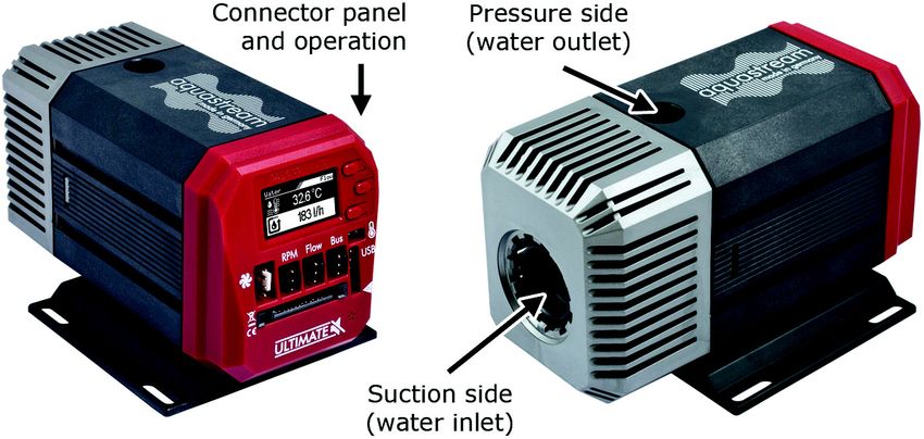
aquacomputer                                                    AQUASTREAM ULTIMATE
       11.3. Pump mode aquabus................................................................16
       11.4. Pump mode deaeration.............................................................16
       11.5. Pump mode temperature set point (Advanced Controller Package
           only)..........................................................................................16
       11.6. Pump mode curve controller (Advanced Controller Package only). .17
       11.7. Pump mode flow controller (Advanced Controller Package only)....17
12. Fan configuration.....................................................................17
       12.1. Fan mode power preset.............................................................17
       12.2. Fan mode temperature set point.................................................18
       12.3. Fan mode aquabus...................................................................18
       12.4. Fan mode curve controller (Advanced Controller Package only).....18
       12.5. Fan mode two point controller (Advanced Controller Package only)19
       12.6. Fan settings..............................................................................19
13. Alarm configuration..................................................................19
       13.1. Acoustic alarm..........................................................................19
       13.2. RPM header function.................................................................19
       13.3. Alarm reporting and alarm limits................................................20
       13.4. System alarms..........................................................................20
14. Sensor configuration.................................................................21
       14.1. External flow sensor...................................................................21
       14.2. Virtual flow sensor (software extension Virtual Flow Sensor only).....21
       14.3. Offsets for temperature sensors..................................................21
       14.4. Software temperature sensors (Advanced Controller Package only). 21
       14.5. Water temperature sensor selection.............................................22
15. Display configuration and information pages..............................22
       15.1. Display settings.........................................................................23
       15.2. Charts.....................................................................................23
       15.3. Display pages...........................................................................23
16. System settings aquastream ULTIMATE.......................................23
       16.1. Device information....................................................................23
       16.2. Factory defaults........................................................................23
       16.3. aquabus configuration..............................................................23
       16.4. Additional features (aquasuite only).............................................24
       16.5. Firmware update and language selection (aquasuite only).............24
17. aquasuite web..........................................................................24
       17.1. Data export..............................................................................24
       17.2. Data access.............................................................................25
       17.3. Data import..............................................................................25
18. Basic settings (aquasuite)...........................................................25
       18.1. Language................................................................................25
       18.2. Units.......................................................................................26
       18.3. Application start-up...................................................................26
       18.4. Service administration...............................................................26
© 2016-2019                      Aqua Computer GmbH & Co. KG                                          -3-
                                Gelliehäuser Str. 1, 37130 Gleichen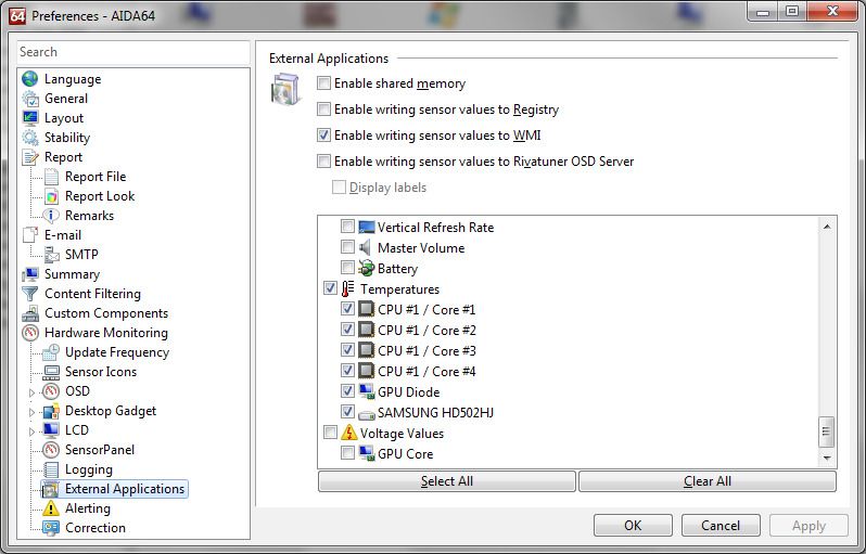
AQUASTREAM ULTIMATE                                                    aquacomputer
       18.5. License manager.......................................................................26
19. Troubleshooting........................................................................27
       19.1. Restore factory defaults..............................................................27
       19.2. Replacement parts....................................................................27
20. Technical details and care instructions........................................28
       20.1. Technical details.......................................................................28
       20.2. Care instructions.......................................................................28
       20.3. Waste disposal.........................................................................28
       20.4. Contact Aqua Computer............................................................28

1. Preface
The aquastream ULTIMATE pump is built for longevity and to match the highest
quality standards. It has been particularly designed for PC water cooling systems.
Each pump is meticulously submitted to a test run; therefore you might find some
moist residues within the pump.
Considering the fast technical development, we reserve the right to perform alter-
ations to the products at any time. It therefore is possible that your product does
not correspond precisely to the descriptions or especially the illustrations in this
manual.

2. Safety precautions
The following safety precautions have to be observed at all times:
   ●  Read this manual thoroughly and entirely!
   ●  Save your data onto suitable media before working on your hardware!
   ●  The pump must not be placed under water!
   ●  The pump controller on the rear end of the pump must not get in contact
      with water!
   ●  The pump may only be used inside a PC case!
   ●  A short rattle noise upon start-up is normal. If the noise persists for a longer
      period of time, there might still be some air inside the pump chamber.
   ●  The pump is not a suction pump. Make sure the pump chamber is filled with
      water prior to operation!
   ●  The pump must never be operated without the rotor! For rotor replacement,
      only the Aqua Computer rotor with order code 41065 may be used!
   ●  The pump is not suited for dry operation!
   ●  Operate only indoors. Not suited for outdoor operation!
   ●  This product is not designed for use in life support appliances, devices, or
      systems where malfunction of this product can reasonably be expected to re-
      sult in personal injury. Aqua Computer GmbH & Co. KG customers using or
      selling this product for use in such application do so at their own risk and

-4-                            Aqua Computer GmbH & Co. KG                             © 2016-2019
                              Gelliehäuser Str. 1, 37130 Gleichen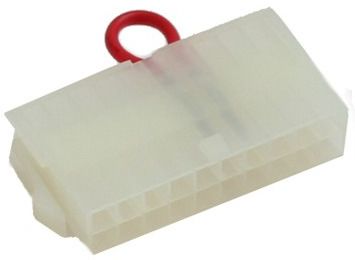
aquacomputer AQUASTREAM ULTIMATE
agree to fully indemnify Aqua Computer GmbH & Co. KG for any damages
resulting from such application!
3. Scope of delivery
● One aquastream ULTIMATE pump
● One internal USB cable (replacement part no. 53085)
● One aquabus/speed signal cable (3 contacts, replacement part no. 93111)
● One ATX adapter for starting the power supply unit (replacement part no.
93112)
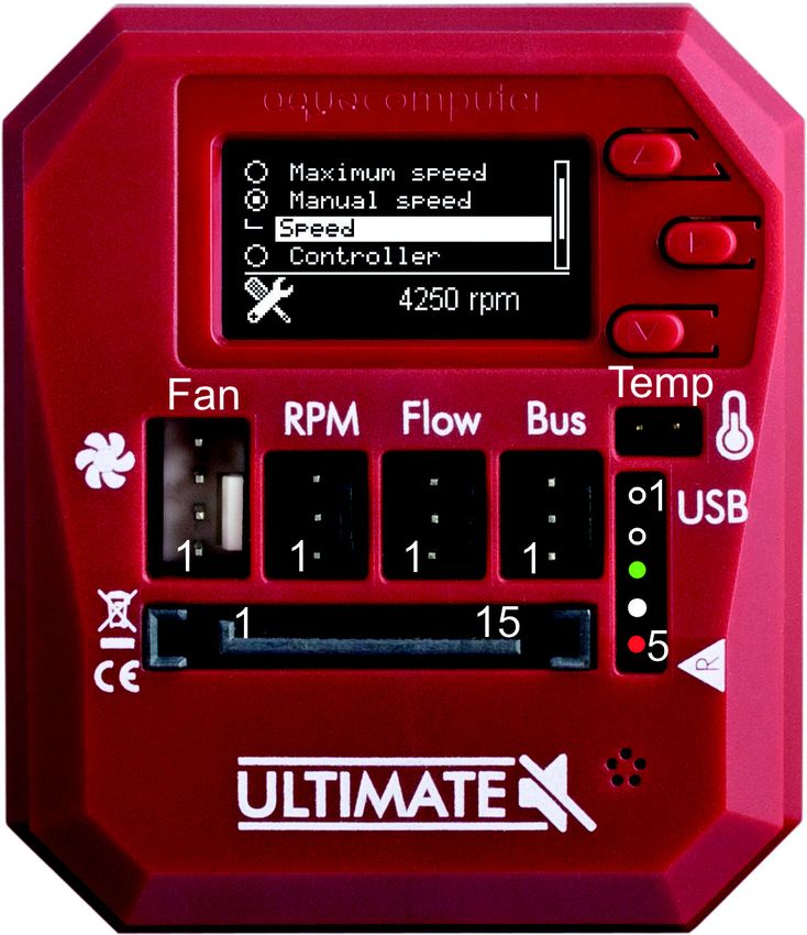
4. Overview of the aquastream ULTIMATE pump
5. Assembly instructions
Install connecting adapters (not included in delivery) to the aquastream ULTIMATE.
The adapters should generally be screwed in without a tool.
tool The black o-ring must
go completely into the pump housing and is not visible if the adapter is correctly
installed. Excessive force may damage the pump!
Should you be using a plug-on reservoir with the pump (e. g. aquainlet series), re-
move the silver suction grille and mount the tank directly onto the water inlet port
of the aquastream ULTIMATE pump. In this case no connecting adapter is to be
installed into the inlet port.
© 2016-2019 Aqua Computer GmbH & Co. KG -5-
Gelliehäuser Str. 1, 37130 Gleichen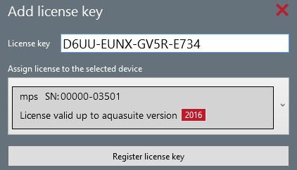
AQUASTREAM ULTIMATE                                            aquacomputer
6. Electrical connections
6.1. Connection panel aquastream ULTI-
                                 ULTI-
MATE
The pump controller board is integrated on the
rear side of the pump. The controller board
features connectors for power supply, fan,
speed signal, aquabus interface, flow sensor,
external temperature sensor and USB interface.
ATTENTION: Completely turn off your power
supply or disconnect the mains power cord
from the wall outlet before connecting or dis-
connecting any cables to/from the device!

6.2. Power Connector
Connect a SATA power plug of your PC's power supply unit to this connector. Do
not use excessive force but double check the polarity of the plug if you are having
trouble to connect.
Pin assignment: Pin 1, 2, 3, 7, 8, 9, 11: not connected
                  Pin 4, 5, 6, 10, 12:    GND
                  Pin 13, 14, 15:         +12 V DC

6.3. Connector “USB”
This connector is used for USB communication with a PC. Connect to an internal
USB header of your motherboard. Take special care to make sure the pin align-
ment matches your motherboard!
Pin assignment: Pin 1: not connected
                  Pin 2: GND (black)
                  Pin 3: D+ (green)
                  Pin 4: D- (white)
                  Pin 5: +5 V (red, arrow mark on pump housing)

6.4. Connector “Bus”
Connector for communication with other Aqua Computer devices.
You can use the aquabus/speed signal cable included in delivery to connect the
pump controller board to a suitable connector of a compatible device, for exam-
ple an aquaero. USB and aquabus interface can be used at the same time, how-
ever not all control options of the aquastream ULTIMATE are available using the
aquabus interface.
Pin assignment: Pin 1: GND
                   Pin 2: aquabus SDA
                   Pin 3: aquabus SCL
-6-                       Aqua Computer GmbH & Co. KG                 © 2016-2019
                         Gelliehäuser Str. 1, 37130 Gleichen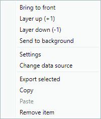
aquacomputer                                        AQUASTREAM ULTIMATE
Compatible aquabus devices:
  ● aquaero 6 XT (53146, 53206, 53250, 53251, 53262, 53263)
  ● aquaero 6 PRO (53145, 53253)
  ● aquaero 6 LT (53234)
  ● aquaero 5 XT (53089, 53125, 53249)
  ● aquaero 5 PRO (53090, 53252)
  ● aquaero 5 LT (53095)

6.5. Connector “Flow”
Flow sensor and special interconnecting cable are optional accessories and not in-
cluded in delivery.
Pin assignment: Pin 1: GND
                    Pin 2: flow sensor +5 V
                    Pin 3: flow sensor signal
Compatible flow sensors:
   ●  Flow sensor with 5.6 mm nozzle (53061)
   ●  Flow sensor “high flow” (53068)
   ●  Connection cable for flow sensor (53027, 53100)

6.6. Connector “RPM”
Depending on configuration, this header can either be used as a generic speed
signal or as a “open collector” switching signal.
For monitoring purposes, this speed signal can be deac-
tivated or the switching signal can be activated in case
of an alarm condition (for configuration see chapter
13.2). For example, the aquabus/speed signal cable in-
cluded in delivery can be used to connect this header to
the CPU fan header of the PC's motherboard and de-
pending on the motherboard and BIOS settings, an au-
tomatic emergency shutdown may be initiated on alarm
condition. Please refer to the motherboard manual for
details on functionality and BIOS settings.
Alternatively, if configured as “power switch (53217)”, this connector can be con-
nected to the power switch header of the motherboard using an additional special-
ized cable (art. 53217, not included in delivery).
Pin assignment: Pin 1: GND
                    Pin 2: not connected
                    Pin 3: speed signal/open collector max. 30 V / 100 mA

6.7. Fan connector
Voltage or PWM regulated fan output. Maximum current is 1 A independent of
output voltage, resulting in a maximum power of 12 W at 12 V, short-term (less

© 2016-2019               Aqua Computer GmbH & Co. KG                         -7-
                         Gelliehäuser Str. 1, 37130 Gleichen
AQUASTREAM ULTIMATE aquacomputer
than 1 second) maximum current is 1.5 A. If output current exceeds 1.5 A or 1 A
for a longer period of time, the output will be permanently disabled and a system
alarm (with alarm buzzer) is triggered. To reactivate the output, the aquastream
ULTIMATE (or the complete PC) has to be disconnected from power for a short pe-
riod of time. The fan output is short-circuit proof.
If required, multiple fans can be connected using standard fan splitter cables as
long as the total current does not exceed output specifications.
Pin assignment: Pin 1: GND
Pin 2: 0-12 V DC output
Pin 3: Speed signal
Pin 4: PWM signal
6.8. Connector for temperature sensor
Connector for a temperature sensor.
Compatible sensors:
● Temperature sensor inline G1/4 (53066)
● Temperature sensor inner/outer thread G1/4 (53067)
● Temperature sensor G1/4 (53147)
● Temperature sensor plug&cool (53025)
● Temperature sensor 70 cm (53026)
7. Operation of the aquastream ULTIMATE
7.1. Initial operation
Turn off your PC or remove the PSU mains cable if the PSU does not have a power
switch. Remove all cables of the PSU (e. g. from non removable disks, optical stor-
age drives or graphic cards). Take special care to disconnect the 4pin or 8pin
ATX12V power supply connector from the motherboard as well. Connect the pow-
er connector of the aquastream ULTIMATE to an available SATA power plug of the
power supply unit.
To operate your aquastream ULTIMATE while
filling the system, you have to either start the PC
power supply with the enclosed ATX start plug
or attach the pump to a second power supply
unit.
To start the power supply unit, plug the ATX
start plug onto the 20pin or 24pin ATX power
supply connector of the PSU. After you have at-
tached the plug to the PSU and turned on the
mains switch of the PSU, the PSU and pump will immediately power up. Proceed
by filling the water cooling system with coolant.
-8- Aqua Computer GmbH & Co. KG © 2016-2019
Gelliehäuser Str. 1, 37130 Gleichenaquacomputer AQUASTREAM ULTIMATE
Important: If you hear rattling noises from the pump, they are most likely caused
by air inside the pump. You can accelerate the deaeration process by carefully tilt-
ing the pump or by activating the deaeration mode of the pump.
After completing the filling process, turn off the PSU and remove the ATX start
plug. Attach all previously disconnected hardware components of the PC to the
power supply unit again.
Please note: Some high-power PSUs will not be able to power the aquastream UL-
TIMATE without further electrical load due to power regulation problems. In this
case, use a second (complete) PC or a separately sold PSU for single components
for the filling process. Alternatively, connect further load like hard disk drives and
optical drives to the PSU.
7.2. Operation via keys and display
The aquastream ULTIMATE is equipped with an OLED display and three keys and
can be fully configured using these.
The upper and lower key will select information pages during display mode and
select and alter menu entries. The middle key will open the device menu while in
display mode and confirm selected menu entries or values while in the menu.
During configuration via keys and display, the aquasuite software should be closed
on a connected PC! Otherwise, the aquasuite will overwrite and thereby cancel
any settings made on the device itself.
7.3. Configuration using USB connection
The aquastream ULTIMATE can be connected to a PC via USB interface and can
then be configured using the aquasuite software. Comprehensive visualization and
logging options are also available in the aquasuite software. However, an USB
connection is not required for operation.
8. aquasuite software
The Windows software aquasuite is an extensive software suite and can be used
for configuration and monitoring. The software is not required for operation
though. All configuration parameters can be saved into the device's memory.
Please note: Depending on the type of product you are using, some features may
not be available for your device.
8.1. Installation of the aquasuite software
For configuration and monitoring of our products with USB interface, the aqua-
suite software is available for download from our website www.aqua-computer.de.
You will find the setup program in the support section of the website under Down-
loads/Software.
© 2016-2019 Aqua Computer GmbH & Co. KG -9-
Gelliehäuser Str. 1, 37130 GleichenAQUASTREAM ULTIMATE aquacomputer
The setup program checks all connected USB devices for embedded software li-
censes and offers various aquasuite versions depending on detected devices. If no
device with a license for the latest aquasuite version is found, a warning is dis-
played and older aquasuite versions that do not require a license purchase can be
selected for installation. For installation and license validation, an internet connec-
tion is required.
The latest aquasuite version may also be installed if no valid license has been
found in a device. Subsequently, a license may be purchased or an existing license
key may be entered within the aquasuite. These functions can be accessed in the
aquasuite/License manager tab.
8.2. Basic operation
The program window is divided into two main areas. On the left side, a list of
“overview pages”, data quick view, data logger, device pages, aquasuite web and
aquasuite configuration is displayed, the right side shows the details of the current-
ly selected list element. The list can be hidden or restored by clicking the arrow
symbol in the upper left corner.
List elements may be minimized or maximized for easier access by clicking the title
bar. The title bars may contain various symbols that will be explained in the follow-
ing chapter.
8.3. Symbols in the headlines
Click the plus symbol in the “Overview pages” headline to create a new
overview page.
Clicking the monitor symbol will toggle desktop mode for this overview
page. While desktop mode is active, the color of the symbol will change
to orange.
Overview page: Clicking the padlock symbol will unlock or lock this over-
view page for editing. Device: Device can not be used due to license
problems, see license manager for details.
Clicking the gear symbol will access the basic configuration page of the
selected list element.
In order to save all settings into a device, click the disk symbol in the
headline.
This symbol indicates that communication with this device is not possible
at the moment. Check USB connection and power supply of the device if
necessary.
Clicking this symbol in the lower left corner of the aquasuite window will
display the news feed on aquasuite updates.
- 10 - Aqua Computer GmbH & Co. KG © 2016-2019
Gelliehäuser Str. 1, 37130 Gleichenaquacomputer AQUASTREAM ULTIMATE
9. Overview pages (aquasuite)
Current sensor readings and diagrams from all supported devices can be dis-
played in overview pages. For each device a pre-configured overview page is au-
tomatically generated the first time the device is connected to the PC. These pages
can be individually modified and new pages can be created. Within one overview
page, data from all connected devices can be accessed.
9.1. Desktop mode
Each overview page can be displayed directly on your desktop. You can enable
desktop mode for an overview page by clicking the corresponding symbol in the
list of overview pages. Desktop mode can only be enabled for one overview page
at a time. With desktop mode enabled, elements of the overview page may cover
program symbols on your desktop, but mouse clicks are transmitted to underlying
desktop symbols.
If a overview page is unlocked for editing while desktop mode is active, the page
will be displayed in the aquasuite window for editing and the current desktop will
be displayed as background for your convenience.
9.2. Creating new overview pages and activating edit mode
In order to create a new overview page, click the plus symbol in the headline
“Overview pages”.
Existing overview pages can be unlocked for editing by clicking lock symbol in the
page listing.
9.3. Adding new elements
If the currently selected overview page is unlocked for editing, a plus symbol is dis-
played in the top right corner of the screen. Click the symbol to add a
new element to the page and select the desired element from the follow-
ing list. All available data is displayed in a tree diagram, click the arrow
symbols to access individual items.
Confirm your selection by clicking the check symbol in the bottom right corner.
The new element will be displayed in the upper left corner and the configuration
window is displayed. Configure the element as described in the next chapters.
© 2016-2019 Aqua Computer GmbH & Co. KG - 11 -
Gelliehäuser Str. 1, 37130 GleichenAQUASTREAM ULTIMATE aquacomputer
9.4. Editing existing elements
If the currently selected overview page is unlocked for
editing, right-clicking an element will access a context
menu.
To access the settings of an element, select “Settings”
in the context menu or simply double click the element.
If you want to move an element, “drag” this element
while holding down the mouse button. Release the
mouse button when the element is at the desired posi-
tion.
9.5. Values and names
If the currently selected overview page is unlocked for editing, right-click an ele-
ment and select “Settings”. You may also double click the element.
Font face, size and color as well as position, decimal places and unit can be con-
figured for individual values.
9.6. Detailed data elements
If the currently selected overview page is unlocked for editing, right-click an ele-
ment and select “Settings”. You may also double click the element. Apart from po-
sition, size and color, the style of the element can be selected and configured. The
following styles are available:
● Headline only: Compact display as a headline.
● Text: Displays the numerical value in a box with a headline.
● Bar graph: Displays numerical value as well as bar graph.
● Chart: Displays the value in chronological sequence as a chart.
● Gauge: Displays the value as a analog gauge.
All display styles offer extensive configuration options, additionally statistical data
such as minimum, maximum and average can be displayed.
9.7. Log data chart
This element can be used to display charts on overview pages. The charts have to
be created using the data log functionality of the aquasuite before they become
available for overview pages. Please refer to the next chapter for details. Once a
chart has been configured, it can be selected from the “Chart selection” list on the
“Display” tab of the settings dialog.
9.8. User defined: Images, text, drawing elements
By using user defined controls, simple drawing elements such as circles, rectangles
and texts as well as images and more sophisticated elements can be added to an
overview page. To do so, add an “User defined” element to an overview page.
Switch to the “Display” tab in following dialog box, select the type of element to be
- 12 - Aqua Computer GmbH & Co. KG © 2016-2019
Gelliehäuser Str. 1, 37130 Gleichenaquacomputer AQUASTREAM ULTIMATE
created from the drop down menu and confirm your selection by clicking the
“Load preset” button. Depending on the type of element, an additional dialog may
appear before the code (XAML, Extensible Application Markup Language) of the
new element is displayed in the lower part of the dialog window. You may want to
customize the code. By clocking the “Ok” Button, the new control is saved to the
overview page.
Step-by-step example to add an image: Select “Image” from the drop down menu
and click the “Load preset” button. Select an image file using the following file se-
lection dialog. The code is then displayed in the lower part of the dialog window
an can be modified. Save the new control by clicking the “Ok” button. The picture
will be displayed on the overview page.
More complex controls such as data bindings and animations are also available
but will require some programming experience for configuration.
9.9. Export and import of overview pages
Elements and complete overview pages can exported from the aquasuite and can
then be imported either on the same PC or on other PCs. For export as well as im-
port, the overview page must be in edit mode.
To export a complete page, right click a free spot of the page and select “Export
page” from the context menu. To export individual elements, select the element or
elements, perform a right click and select “Export selected” from the context menu.
For import, right click a free spot of the page and select “Import page” or “Import
items”from the context menu. Using “Import page”, the current page will be delet-
ed and only the imported page items will be displayed, using “Import items” will
add the items from file to the current page without altering the existing items. Dur-
ing import, the elements will be assigned to devices using the following scheme:
If a device with identical serial number is found on the computer, no changes are
made.
If no device with identical serial number is found on the computer, the element will
be assigned to the first device found of identical type.
When importing complex pages with elements referring to more than one device, it
is recommended to edit the device assignment in the file using a text editor prior to
importing.
10. Data quick view and data log (aquasuite)
All data currently monitored by the aquasuite can be accessed in the “Data quick
view” section. This includes data from connected USB devices as well as hardware
data supplied by the Aqua Computer background service. Displayed data may be
filtered using the text box next to the magnifier icon, a chart shows the develop-
ment over a maximum of ten minutes. All data shown here is not stored perma-
nently.
© 2016-2019 Aqua Computer GmbH & Co. KG - 13 -
Gelliehäuser Str. 1, 37130 GleichenAQUASTREAM ULTIMATE aquacomputer
In contrast, the “Data log” may be used to selectively and permanently store data
from all connected Aqua Computer devices and hardware data supplied by the
background service. Logged data can then be analyzed by creating charts or be
exported to files. Data is only logged while the aquasuite software is being execut-
ed.
10.1. Log settings
The log settings can be accessed by clicking the “Log settings” element below the
“Data log” headline in the listing. To log data, create a new log data set by click-
ing the plus symbol in the upper right corner of the settings window. Enter name,
time interval and configure automatic deletion of old data to meet your require-
ments. You may then add the data sources to log by clicking the plus symbol in
the “Data sources” window section. You may add an unlimited number of data
sources to each log data set, the total number of log data sets is also unlimited.
10.2. Analyze data
Logged data can be visually evaluated as charts. To do so, select “Analyze data”
below the “Data log” headline in the listing. The chart will initially be empty, di-
rectly below the chart are eight buttons to modify the chart. In the lower section of
the window, the chart data can be configured.
To add data to the chart, first select the “Data sources” tab in the chart configura-
tion and select a data set to be displayed. If no data sources are available, you
will have to configure the log settings as described in the chapter “Log settings” of
this manual. Select the time period to be displayed on the right side of the window
and add the data to the chart by clicking the “Add data to chart” button. Repeat
this procedure if you want to display more than one data set in the chart.
You may modify the chart using the “Chart setup” and “Data series setup” tabs.
Finally, you can use the “Chart manager” tab to save the current chart configura-
tion and to load or delete previously saved configurations. All saved chart configu-
rations will be available on overview pages for the “Log data chart” element.
The currently displayed chart can be edited by using the buttons directly below the
chart and may also be saved as an image file. The button corresponding to the
currently selected function is highlighted by an orange frame. Please refer to the
following list for details on each function:
To save the currently displayed chart as an image file, click the floppy
disk symbol and select a name and location in the following dialog.
This function can be used to add horizontal lines to the chart. While this
function is activated, simply click into the chart to add a line at the current
cursor position.
This function can be used to add vertical lines to the chart. While this
function is activated, simply click into the chart to add a line at the current
cursor position.
- 14 - Aqua Computer GmbH & Co. KG © 2016-2019
Gelliehäuser Str. 1, 37130 Gleichenaquacomputer AQUASTREAM ULTIMATE
This function can be used to add annotations to the chart. While this
function is activated, simply click into the chart to add an annotation at
the current cursor position. By clicking into the text box, you may edit the
text. You may also drag the little circle beside the text box to move the connecting
line to the desired position. Use drag and drop to move existing annotations.
This function can be used to remove horizontal/vertical lines or annota-
tions from the chart. While this function is activated, simply click the ele-
ment to be removed.
This function can be used to move the visible portion of the chart. Press
and hold the mouse button while moving the cursor in the chart to select
the position to be displayed, then release the button.
This function can be used to zoom in and out. Use the mouse wheel or
select the area to be displayed. You can reset the zoom settings by dou-
ble-clicking in the chart area.
This function will completely remove the chart.
10.3. Manual data export
Saved data can be exported from the data log into a XML file. To do so, select
“Analyze data” below the “Data log” headline in the listing. Select the “Data
sources” tab in the chart configuration and select a data set to be exported. If no
data sources are available, you will have to configure the log settings as described
in the chapter “Log settings” of this manual. Select the time period to be exported
on the right side of the window and start the export process by clicking the “Export
data” button. Enter a file name and path in the following dialog window.
10.4. Automatic data export
The automatic data export feature can be used to save data from the aquasuite
into an XML file on the hard disk or in the RAM (“memory mapped file”) in a regu-
lar time interval. The automatic data export will always overwrite the previously
saved data, so the file always contains only the most recent data set. Select “Auto-
matic data export” below the “Data log” headline in the listing to access the set-
tings screen. Create a new export data set by clicking the plus symbol in the upper
right corner of the screen. Enter name, path and time interval to meet your re-
quirements. You may then add the data sources to log by clicking the plus symbol
in the “Data sources” window section. You may add an unlimited number of data
sources to each export data set, the total number of export data sets is also unlim-
ited.
© 2016-2019 Aqua Computer GmbH & Co. KG - 15 -
Gelliehäuser Str. 1, 37130 GleichenAQUASTREAM ULTIMATE aquacomputer
11. Pump configuration
aquasuite: Select “Pump” from the device list below the “aquastream ULTIMATE”
entry. In the upper area, current pump data is displayed as plain text as well as in
a diagram. Select the desired mode of operation below the diagram.
Device menu: Select “Pump” from the menu list and confirm by pressing the mid-
dle key.
11.1. Pump mode maximum power/automatic
If maximum power/automatic mode is selected, the pump will automatically oper-
ate at the highest attainable speed. The pump controller constantly monitors rotor
orientation, electrical current, power dissipation and supply voltage to calculate
optimum rotation speed. Using a standard water cooling setup, this speed will nor-
mally be around 4000 – 5000 rpm depending on the resistance of the system.
If “Manual speed settings” is selected, you can set the rotation speed of the pump
manually. If the selected speed cannot be attained, the pump controller will use
the highest stable rotation speed (below the set speed) just like in automatic mode.
11.2. Pump mode speed preset
If speed preset mode is selected, you can manually set the desired rotation speed
of the pump. If the selected speed cannot be attained, the pump controller will use
the highest stable rotation speed just like in automatic mode.
11.3. Pump mode aquabus
This mode can be used to control pump speed by an aquaero 5/6 controller con-
nected to the pump via aquabus. If no data is transmitted to the pump via
aquabus, the pump controller will use the highest stable rotation speed just like in
automatic mode.
11.4. Pump mode deaeration
While in deaeration mode, the pump will stop and run at top speed at regular in-
tervals to speed up the deaeration process. Deaeration mode is deactivated after
ten minutes.
11.5. Pump mode temperature set point (Advanced Controller Package only)
This mode can be used to automatically adjust pump speed depending on the cur-
rent temperature reading of one of the up to four available temperature sensors.
The desired target temperature can be configured, all other parameters should not
be changed for normal operation.
- 16 - Aqua Computer GmbH & Co. KG © 2016-2019
Gelliehäuser Str. 1, 37130 Gleichenaquacomputer AQUASTREAM ULTIMATE
Please note that pump speed and the resulting changes in flow rate have only a
minor influence on temperatures in a typical water cooling setup. This mode may
therefore not effect the expected results.
11.6. Pump mode curve controller (Advanced Controller Package only)
This mode can be used to automatically adjust pump speed depending on the cur-
rent temperature reading of one of the up to four available temperature sensors.
The controller curve can be configured by assigning output values to 16 corre-
sponding temperature values. The output values in percent correlate to the pump
speed range from 3000 to 5500 rpm. So a value of 50 % correlates to a pump
speed of 4250 rpm, a change of 1 % correlates to a speed change of 25 rpm. If
the selected speed cannot be attained, the pump controller will use the highest sta-
ble rotation speed instead.
In the aquasuite, controller curves can easily be adjusted using drag & drop and
curves can automatically be generated from start and end points. In the graphical
curve display, the currently displayed area can be changed using the following
methods:
● Mouse wheel movements will zoom in and out.
● A double click on an axis will reset zoom level for this axis, a double click
into the diagram will reset both axes.
● Selecting an area on an axis will zoom this axis to this area, selecting an
area in the diagram will zoom both axes to this area.
● Mouse movement while right button is pressed will move the displayed area
of the diagram.
11.7. Pump mode flow controller (Advanced Controller Package only)
This mode can be used to automatically adjust pump speed depending on the cur-
rent flow rate. This requires either an additional external flow sensor or the pur-
chase of the virtual flow sensor software extension. The desired flow rate can be
configured between 30 to 300 liters per hour.
12. Fan configuration
aquasuite: Select “Fan” from the device list below the “aquastream ULTIMATE”
entry. In the upper area, current fan data is displayed as plain text as well as in a
diagram. Select the desired mode of operation below the diagram.
Device menu: Select “Fan” from the menu list and confirm by pressing the middle
key.
12.1. Fan mode power preset
If power preset mode is selected, you can manually set the desired output power of
the fan output. The values in percent correlate to the either the voltage range from
© 2016-2019 Aqua Computer GmbH & Co. KG - 17 -
Gelliehäuser Str. 1, 37130 GleichenAQUASTREAM ULTIMATE aquacomputer
0 V to 12 V in voltage controlled mode or the PWM ratio range from 0 % to 100
% in PWM controlled mode.
12.2. Fan mode temperature set point
This mode can be used to automatically adjust fan speed depending on the cur-
rent temperature reading of one of the up to four available temperature sensors.
The desired target temperature can be configured, all other parameters should not
be changed for normal operation.
12.3. Fan mode aquabus
This mode can be used to fan speed by an aquaero 5/6 controller connected to
the pump via aquabus. If no data is transmitted to the pump via aquabus, the fan
output will be set to maximum power.
12.4. Fan mode curve controller (Advanced Controller Package only)
This mode can be used to automatically adjust fan speed depending on the cur-
rent temperature reading of one of the up to four available temperature sensors.
The controller curve can be configured by assigning output values to 16 corre-
sponding temperature values.
The output value in percent corresponding to the current temperature is scaled to
the range between minimum and maximum fan power settings before being ap-
plied to the fan output.
The startup temperature will also be factored into the controller output. The output
power defined in the curve controller will be ignored and set to 0 % as long as the
input temperature has not exceeded the defined startup temperature for the first
time. After the startup temperature has been exceeded, the output will strictly be
set according to the defined curve until the output value goes down to 0 % again.
This will trigger the startup process again, meaning the temperature has to exceed
the defined startup temperature again before the curve will be in effect once more.
This behavior is meant to prevent fans assigned to the curve controller to be
switched on and off in rapid succession. If the first point on the curve is set to a
power greater than 0 %, this behavior is deactivated.
In the aquasuite, controller curves can easily be adjusted using drag & drop and
curves can automatically be generated from start and end points. In the graphical
curve display, the currently displayed area can be changed using the following
methods:
● Mouse wheel movements will zoom in and out.
● A double click on an axis will reset zoom level for this axis, a double click
into the diagram will reset both axes.
● Selecting an area on an axis will zoom this axis to this area, selecting an
area in the diagram will zoom both axes to this area.
- 18 - Aqua Computer GmbH & Co. KG © 2016-2019
Gelliehäuser Str. 1, 37130 Gleichenaquacomputer AQUASTREAM ULTIMATE
● Mouse movement while right button is pressed will move the displayed area
of the diagram.
12.5. Fan mode two point controller (Advanced Controller Package only)
The two point controllers mode will result in switching the fan output on and off
when the temperature reading of the selected temperature sensor rises above/falls
below predefined values.
12.6. Fan settings
Depending on currently selected fan mode, additional parameters can be config-
ured.
In voltage controlled mode (for conventional 3-pin fans), output voltage is adjust-
ed to control the fan. In PWM mode (for 4-pin PWM fans), a PWM signal is gener-
ated and adjusted on the dedicated PWM pin, output voltage is set to 12 V.
The start boost feature can be used to reliably power up a fan or pump connected
to the output. If activated, the aquastream ULTIMATE controller will set the fan out-
put to the 100 % power for a short duration before switching to normal operation
whenever the output power changes from exactly 0 % setting to a higher value.
The fan output range can be limited by setting “Minimum power” and ”Maximum
power” values correspondingly. The check box “Hold minimum power” determines
whether the fan will be switched off during a power setting of 0 % (box not
checked) or remain active at the set minimum speed (box checked). Set minimum
power to a value at which the connected fan reliably starts up.
The “Maximum rotation speed of connected fan” setting applies only to diagram
scaling within the aquasuite and has no effect on the fan output.
13. Alarm configuration
aquasuite: Select “Alarms” from the device list below the “aquastream ULTIMATE”
entry.
Device menu: Select “Alarms” from the menu list and confirm by pressing the mid-
dle key.
13.1. Acoustic alarm
This parameter determines whether the alarm buzzer will activated during alarm
conditions. The alarm buzzer is always active for non-configurable systems alarms
regardless of this setting.
13.2. RPM header function
Select the signal to be provided through the speed signal output:
● Speed signal disabled during alarm: A speed signal is generated as long as
no alarm condition is detected. Allows for alarm monitoring if RPM header
of the pump is connected to a fan header with speed signal monitoring.
© 2016-2019 Aqua Computer GmbH & Co. KG - 19 -
Gelliehäuser Str. 1, 37130 GleichenAQUASTREAM ULTIMATE aquacomputer
● Speed signal permanently on: Speed signal is always generated regardless
of alarm events.
● Power switch (53217): This mode can be used for emergency shutdown of
the PC, if the “RPM” header is connected to the power switch header of the
motherboard using a suitable cable (art. 53217). Before connecting the ca-
ble, make sure the pump is configured correctly! After connecting the cable,
test the setup by deliberately creating an alarm condition. If the PC is not
shut down, the cable header connected to the motherboard must be rotated
by 180 degrees and the test has to be repeated. Emergency shutdown may
result in data loss as operating system and running programs are not shut
down properly!
13.3. Alarm reporting and alarm limits
Select the data sources to be monitored and set appropriate alarm limits. If the
current reading is below the limit (flow sensors) or higher than the limit (tempera-
ture sensors) or no fan speed signal is detected, an alarm will be raised if the
check box “Activate alarm evaluation” is set for this value.
While an alarm condition is detected, the pump display will permanently show a
corresponding information screen. If more than one alarm is active, the displayed
information will alternate between corresponding screens in short order. To
change the alarm configuration, you may still access the menu during alarm con-
ditions by pressing the middle key next to the display.
On the alarm page within the aquasuite, all sources that currently raise an alarm
are highlighted with a red background color. Alarms that have been active at least
once since pump start-up, but are not active presently, are highlighted with a yel-
low background color.
Make sure only to use readings for alarm evaluation that are functional with your
specific setup.
13.4. System alarms
System alarms are raised for severe malfunctions and can not be configured. If a
system alarm is detected, the water cooling system will be either inoperational or
severely impaired, instant action (shutdown of the PC) is mandatory! The alarm
buzzer is activated whenever a system alarm is detected.
The following system alarms can be detected:
● Supply voltage too high: Pump function deactivated, fan output deactivated.
Shut down PC immediately!
● Supply voltage too low: Pump operational with reduced power, fan output
deactivated. Shut down PC immediately if fan output is required!
● Pump current too high: Pump function deactivated. Shut down PC immedi-
immedi-
ately!
● Pump current too low: Pump function deactivated. Shut down PC immedi-
immedi-
ately!
- 20 - Aqua Computer GmbH & Co. KG © 2016-2019
Gelliehäuser Str. 1, 37130 Gleichenaquacomputer AQUASTREAM ULTIMATE
● Fan current too high: Fan output deactivated. Shut down PC immediately!
● Fan amp error: Fan output deactivated. Shut down PC immediately!
14. Sensor configuration
aquasuite: Select “Sensors” from the device list below the “aquastream ULTIMATE”
entry.
Device menu: Select “Sensors” from the menu list and confirm by pressing the
middle key.
14.1. External flow sensor
Calibration values for sensors sold by Aqua Computer can conveniently be select-
ed from a drop-down list. Select the appropriate entry for the flow sensor connect-
ed to the aquastream ULTIMATE.
If necessary, the flow rate can be calibrated by ±10 %.
14.2. Virtual flow sensor (software extension Virtual Flow Sensor only)
If the software extension “Virtual Flow Sensor” is activated, the aquastream ULTI-
MATE continuously calculated the current flow rate from a variety of pump param-
eters.
If necessary, the flow rate can be calibrated by ±10 %. Flow rates below 40 l/h
will not be displayed due to increasing imprecision of the calculation method for
low flow rates.
Limitations: Flow rate can not be calculated if a second pump is present in the
cooling circuit! Flow rate calculation is calibrated for DP Ultra viscosity and will
deviate when using other coolants ore pure water!
14.3. Offsets for temperature sensors
If necessary, each temperature sensor can be calibrated by adding an offset of
±15 °C.
14.4. Software temperature sensors (Advanced Controller Package only)
Software temperature sensors can be used to transfer temperature sensor readings
to the aquastream ULTIMATE from the computer by USB connection or from an
aquaero 5/6 by aquabus connection. Two procedures are implemented:
1. Sensor data is transmitted from an aquaero 5/6 connected to the aquas-
tream ULTIMATE via aquabus.
2. During installation of the aquasuite, the background service “Aqua Comput-
er Service” is also installed. This service supplies various data from PC com-
ponents, additionally sensor data provided by third party software can be
accessed. In order to access third party software data, the third party soft-
ware has to be correctly installed, configured and running.
© 2016-2019 Aqua Computer GmbH & Co. KG - 21 -
Gelliehäuser Str. 1, 37130 GleichenAQUASTREAM ULTIMATE aquacomputer
Currently, the “Aqua Computer Service” supports data transfer from "HWiNFO“
(REALiX, Freeware, www.hwinfo.com) and "AIDA64“ (FinalWire Ltd., subject to li-
cense fees, www.aida64.com).
HWiNFO automatically exports all temperature sensor values and does not need
to be configured. When using HWiNFO, the “Sensor Status” Window has to be
open.
In the AIDA64 preferences menu, writing to WMI must be activated in the "external
applications“ sub-menu:
Click the “Select data source” button to assign each software sensor to a tempera-
ture sensor provided by third party software.
14.5. Water temperature sensor selection
Select one of the available temperature sensors to be displayed as “Water temper-
ature” in the information pages on the pump display. This sensor is also available
as a data source for all temperature controllers. If the currently selected sensor
does not read valid data, the pump will automatically default to the internal water
temperature sensor instead.
15. Display configuration and information pages
aquasuite: Select “Display” from the device list below the “aquastream ULTIMATE”
entry.
Device menu: Select “Display” from the menu list and confirm by pressing the mid-
dle key.
- 22 - Aqua Computer GmbH & Co. KG © 2016-2019
Gelliehäuser Str. 1, 37130 Gleichenaquacomputer AQUASTREAM ULTIMATE
15.1. Display settings
Units for temperature and flow measurement can be selected, display brightness
and page interval can be adjusted.
15.2. Charts
Four configurable chart pages are available to be displayed in the pump display.
Data source and refresh rate can be selected for each chart.
15.3. Display pages
During normal operation, a variety of predefined display pages are available.
Each of these pages can be activated or deactivated individually.
16. System settings aquastream ULTIMATE
aquasuite: Select “System” from the device list below the “aquastream ULTIMATE”
entry.
Device menu: Select “System” from the menu list and confirm by pressing the mid-
dle key.
16.1. Device information
The details displayed here might be required when you contact our service for sup-
port. You may enter a “Device description” for easier identification, this text will be
displayed in the device list and in the data quick view.
16.2. Factory defaults
Click the button “Reset device to factory defaults” in the aquasuite or select the
“Factory defaults” entry from the menu for a complete reset of all settings. You will
have to completely reconfigure the device after resetting it to factory defaults!
16.3. aquabus configuration
Before connecting two aquastream pumps simultaneously to an aquaero 5/6 via
aquabus, each pump has to be configured to a unique aquabus address. If only
one device is connected via aquabus, this step may be skipped. Address 17 and
18 are available. Please note that aquastream ULTIMATE and aquastream XT as
well as D5 NEXT share resource assignments in the aquabus device handling of
the aquaero. A combined maximum of two pumps of these types can be managed
by the aquaero.
Changes to the bus address or aquabus sensor configuration are effective within a
few seconds. However, it may take up to five minutes for a connected aquaero to
update its configuration.
© 2016-2019 Aqua Computer GmbH & Co. KG - 23 -
Gelliehäuser Str. 1, 37130 GleichenAQUASTREAM ULTIMATE aquacomputer
16.4. Additional features (aquasuite only)
Two additional feature are available for the aquastream ULTIMATE, the advanced
controller package and the virtual flow sensor extension. After initial operation,
both features are activated for a trial period of 48 hours of operation. The features
are deactivated after expiration of this trial period, but can be permanently en-
abled at any time by purchasing a software key. To buy a key, please click one of
the buttons in the aquasuite software, you will be redirected to a corresponding
web portal on our website (internet connection required).
After having received a key file, you can simply drag&drop this file from your email
program or file system to the “activate function” button, or click the button and se-
lect the file manually. The new features are immediately activated.
16.5. Firmware update and language selection (aquasuite only)
The most up to date firmware for all supported devices is always included in the
current version of the aquasuite software. The button “ Update firmware now” will
start the update process for the device firmware.
During the firmware update process, the language of the pump menu will auto-
matically be set to the currently selected language in the aquasuite software. To
change the language of the pump menu, first select the desired language in the
basic aquasuite settings and restart the aquasuite software. Afterwards, perform a
firmware update of the aquastream ULTIMATE to change the language of the
pump.
During the firmware update process, do not disconnect the device from the PC
and do not power down the PC! After the firmware is successfully updated, the
aquasuite software will be automatically closed.
17. aquasuite web
Click the entry “aquasuite web” to publish data on the internet or import data from
the internet. The server for this service is operated by Aqua Computer and provid-
ed for use with the aquasuite, without warranty for for error free operation or per-
manent availability. Aqua Computer reserves the right to limit or cancel this service
at any time.
17.1. Data export
To publish data, create a new export data set by clicking the plus symbol in the
upper right corner of the “Data export” window. The name of the data set may be
modified to meet your requirements. You may then add the data sources to export
by clicking the plus symbol in the “Data sources” window section. By clicking the
gear symbol, the name of the corresponding value can be changed. Up to 30
data sources can be added to each export data set, the total number of export
- 24 - Aqua Computer GmbH & Co. KG © 2016-2019
Gelliehäuser Str. 1, 37130 GleichenYou can also read