Adafruit Ultimate GPS - Created by lady ada - Last updated on 2020-09-04 01:27:50 AM EDT
←
→
Page content transcription
If your browser does not render page correctly, please read the page content below
Adafruit Ultimate GPS
           Created by lady ada

Last updated on 2020-09-04 01:27:50 AM EDT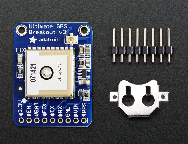
Overview

We carry a few different GPS modules here in the Adafruit shop, but none that satisfied our every desire - that's why
we designed this little GPS breakout board. We believe this is the Ultimate GPS module, so we named it that. It's got
everything you want and more:

      -165 dBm sensitivity, 10 Hz updates, 66 channels
      5V friendly design and only 20mA current draw
      Breadboard friendly + two mounting holes
      RTC battery-compatible
      Built-in datalogging
      PPS output on fix
      Internal patch antenna + u.FL connector for external active antenna
      Fix status LED

The breakout is built around the MTK3339 chipset, a no-nonsense, high-quality GPS module that can track up to 22
satellites on 66 channels, has an excellent high-sensitivity receiver (-165 dB tracking!), and a built in antenna. It can do
up to 10 location updates a second for high speed, high sensitivity logging or tracking. Power usage is incredibly low,
only 20 mA during navigation.

 © Adafruit Industries                 https://learn.adafruit.com/adafruit-ultimate-gps                        Page 4 of 54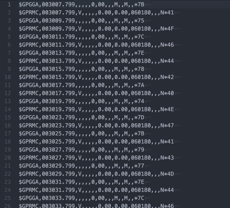
Ultimate GPS Breakout Board
The Breadboard Breakout board comes with: a ultra-low dropout 3.3V regulator so you can power it with 3.3-5VDC in,
5V level safe inputs, ENABLE pin so you can turn off the module using any microcontroller pin or switch, a footprint for
optional CR1220 coin cell to keep the RTC running and allow warm starts and a tiny bright red LED. The LED blinks at
about 1Hz while it's searching for satellites and blinks once every 15 seconds when a fix is found to conserve power. If
you want to have an LED on all the time, we also provide the FIX signal out on a pin so you can put an external LED on.

 © Adafruit Industries               https://learn.adafruit.com/adafruit-ultimate-gps                     Page 5 of 54
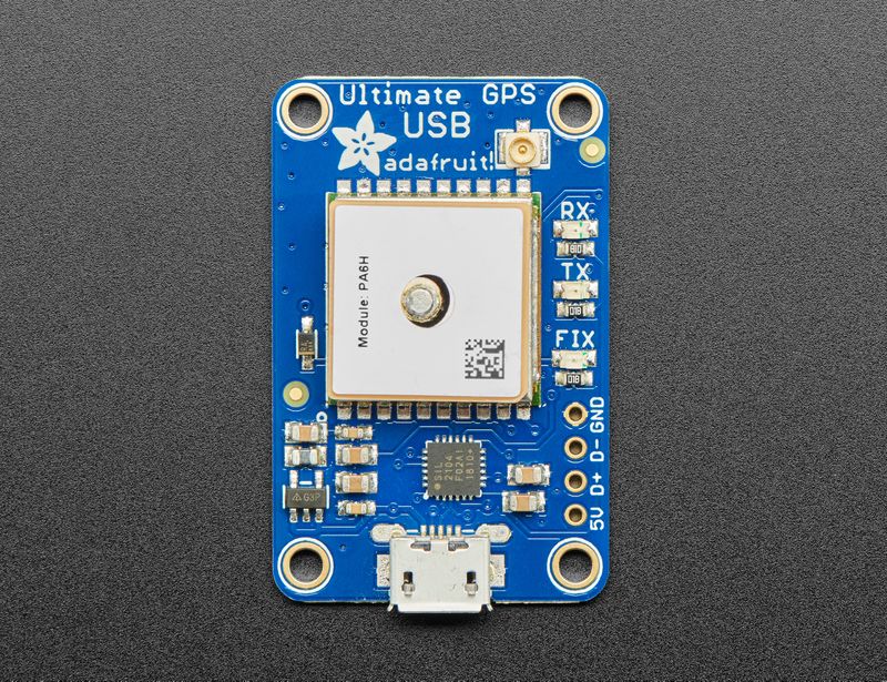
Ultimate GPS USB Board
The USB Breakout board comes with: 4-pin USB breakout for direct-soldering or connection to a USB host, two yellow
receive/transmit LEDs let you know when data is being transmitted to or from the GPS module serial interface, a
footprint for optional CR1220 coin cell to keep the RTC running and allow warm starts and a tiny bright red LED. The
LED blinks at about 1Hz while it's searching for satellites and blinks once every 15 seconds when a fix is found to
conserve power. If you want to have an LED on all the time, we also provide the FIX signal out on a pin so you can put
an external LED on.

Antenna Usage
Two features that really stand out about version 3 MTK3339-based module is the external antenna functionality and
the the built in data-logging capability. The module has a standard ceramic patch antenna that gives it -165 dB
sensitivity, but when you want to have a bigger antenna, you can snap on any 3V active GPS antenna via the uFL
connector. The module will automatically detect the active antenna and switch over! Most GPS antennas use SMA
connectors so you may want to pick up one of our uFL to SMA adapters. (http://adafru.it/851)

The other cool feature of the new MTK3339-based module (which we have tested with great success) is the built in
datalogging ability. Since there is a microcontroller inside the module, with some empty FLASH memory, the newest
firmware now allows sending commands to do internal logging to that FLASH. The only thing is that you do need to
have a microcontroller send the "Start Logging" command. However, after that message is sent, the microcontroller
can go to sleep and does not need to wake up to talk to the GPS anymore to reduce power consumption. The time,
date, longitude, latitude, and height is logged every 15 seconds and only when there is a fix. The internal FLASH can
store about 16 hours of data, it will automatically append data so you don't have to worry about accidentally losing data
if power is lost. It is not possible to change what is logged and how often, as its hardcoded into the module but we
found that this arrangement covers many of the most common GPS datalogging requirements.

Pick one up today at the Adafruit shop! (http://adafru.it/746)

 © Adafruit Industries                https://learn.adafruit.com/adafruit-ultimate-gps                     Page 6 of 54

Specifications:
Module specs:

     Satellites: 22 tracking, 66 searching
     Patch Antenna Size: 15mm x 15mm x 4mm
     Update rate: 1 to 10 Hz
     Position Accuracy: 1.8 meters
     Velocity Accuracy: 0.1 meters/s
     Warm/cold start: 34 seconds
     Acquisition sensitivity: -145 dBm
     Tracking sensitivity: -165 dBm
     Maximum Velocity: 515m/s
     Vin range: 3.0-5.5VDC
     MTK3339 Operating current: 25mA tracking, 20 mA current draw during navigation
     Output: NMEA 0183, 9600 baud default
     DGPS/WAAS/EGNOS supported
     FCC E911 compliance and AGPS support (Offline mode : EPO valid up to 14 days )
     Up to 210 PRN channels
     Jammer detection and reduction
     Multi-path detection and compensation

Breakout board details:

     Weight (not including coin cell or holder): 8.5g
     Dimensions (not including coin cell or holder): 25.5mm x 35mm x 6.5mm / 1.0" x 1.35" x 0.25"

If you purchased a module before March 26th, 2012 and it says MTK3329 on the silkscreen, you have the PA6B
version of this breakout with the MT3329 chipset. The MTK3329 does not have built in datalogging. If your module has
sharpie marker crossing out the MTK3329 text or there is no text, you have a PA6C MTK3339 with datalogging ability.
If you have the version with "v3" next to the name, you have the PA6H which has PPS output and external-antenna
support

This tutorial assumes you have a '3339 type module.

 © Adafruit Industries              https://learn.adafruit.com/adafruit-ultimate-gps                   Page 7 of 54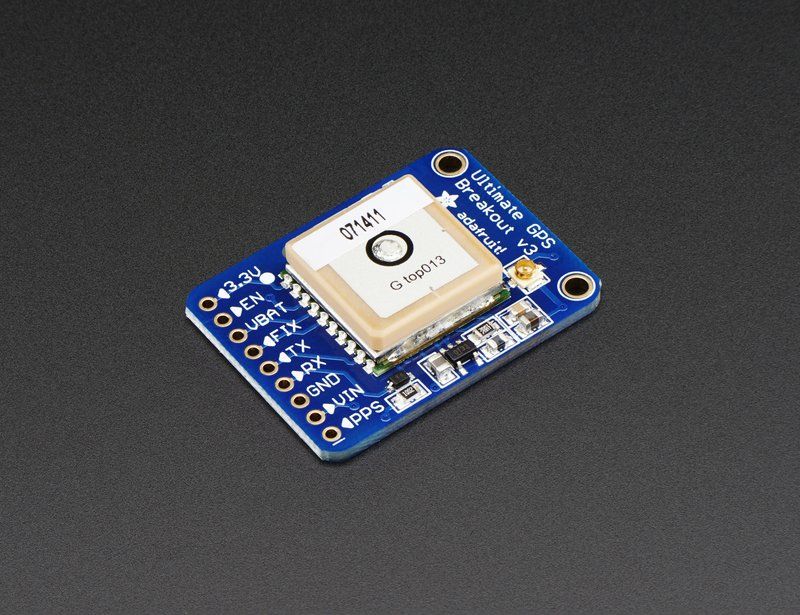
Pinouts

                                                              The plain GPS breakout is meant to be used with a
                                                              microcontroller that has a 3/5V UART and has all the
                                                              GPIO pins exposed on the bottom 0.1" header

                                                              The USB version doesn't have those breakouts. Instead
                                                              it has a single USB serial port. There's 4 pads to the
                                                              right side that are the USB pinouts for when you want to
                                                              solder it directly to a USB host converoller.

Breakout Power Pins

These are the pins that are involved with powering the GPS. Starting from the right are the required power pins:

     VIN - power input, connect to 3-5VDC. It's important to connect to a clean and quiet power supply. GPS's are very
     sensitive, so you want a nice and quiet power supply. Don't connect to a switching supply if you can avoid it, an
     LDO will be less noisy!

 © Adafruit Industries               https://learn.adafruit.com/adafruit-ultimate-gps                     Page 8 of 54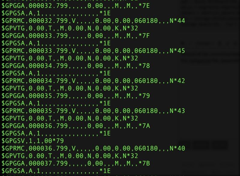
GND - power and signal ground. Connect to your power supply and microcontroller ground.

Then, on the left are some optional power pins:

      VBAT is an input pin - it is connected to the GPS real time clock battery backup. We suggest using the battery
      spot on the back but if you have a project with a coin cell or other kind of battery that you want to use (and its
      under 3.3V) you can connect it to the VBAT pin. For V1 and V2 modules: If you do this, be sure to cut the trace on
      the back between the RTC solder pads
      EN is the Enable pin, it is pulled high with a 10K resistor. When this pin is pulled to ground, it will turn off the GPS
      module. This can be handy for very low power projects where you want to easily turn the module off for long
      periods. You will lose your fix if you disable the GPS and it will also take a long time to get fix back if you dont
      have the backup battery installed.
      3.3V is the output from the onboard 3.3V regulator. If you have a need for a clean 3.3V output, you can use this! It
      can provide at least 100mA output.

Breakout Serial Data Pins

Next pins you'll want to use are the serial data pins:

      TX - the pin that transmits data from the GPS module to your microcontroller or computer. It is 3.3V logic level.
      Data comes out at 9600 baud by default
      RX - the pin that you can use to send data to the GPS. You can use use 3.3V or 5V logic, there is a logic level
      shifter. By default it expects 9600 baud data, and remember you need to send it checksum'med NMEA
      sentences

Breakout Other Pins

 © Adafruit Industries                 https://learn.adafruit.com/adafruit-ultimate-gps                        Page 9 of 54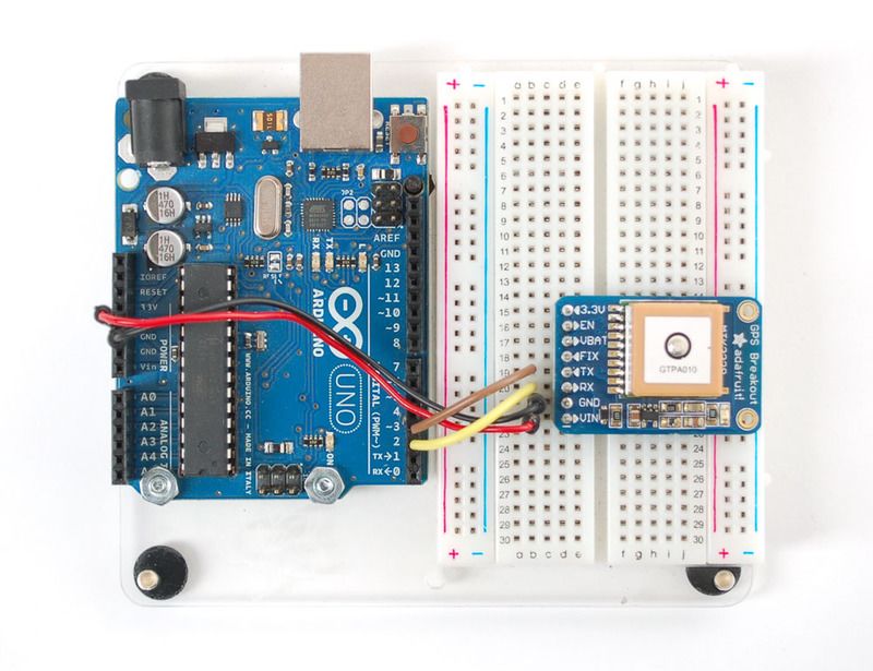
FIX is an output pin - it is the same pin as the one that drives the red LED. When there is no fix, the FIX pin is going to
pulse up and down once every second. When there is a fix, the pin is low (0V) for most of the time, once every 15
seconds it will pulse high for 200 milliseconds

PPS is a new pin output on V3 modules. Its a "pulse per second" output. Most of the time it is at logic low (ground) and
then it pulses high (3.3V) once a second, for 50-100ms, so it should be easy for a microcontroller to sync up to it

 © Adafruit Industries                 https://learn.adafruit.com/adafruit-ultimate-gps                      Page 10 of 54
Battery Backup
The GPS has a built in real time clock, which can keep track of time even when it power is lost and it doesn't have a fix
yet. It can also help reduce fix times, if you expect to have a flakey power connection (say you're using solar or similar).
To use the RTC, we need to attach a battery. There is a spot on the back for a CR1220 sized battery holder. We
provide the holder but the battery is not included. You can use any 12mm coin cell - these are popular and we also
carry them in the Adafruit shop.

Normally, if the GPS loses power, it will revert to the factory default for baud rates, configuration, etc. A backup battery
will mean that those defaults will not be lost!

The backup real-time-clock circuitry draws 7 uA (0.007 mA) so a CR1220 will last 40mAh / 0.007mA = 5,714 hours =
240 days continuously. The backup battery is only used when there's no main 3V power to the GPS, so as long as it's
only used as backup once in a while, it will last years

If you have a v1 or v2 module ONLY:
Before inserting a battery into the battery holder, first cut the trace between the two solder pads on the back, labeled
RTC (this disconnects the VIN pin from the battery input) Use a multimeter with continuity checking to verify the two
pads are no longer tied together.

V3 modules do not have a trace to cut, they have a built-in diode!

 © Adafruit Industries                 https://learn.adafruit.com/adafruit-ultimate-gps                      Page 11 of 54

Remember, the GPS does not know what time zone you are in (even though it knows your location, there is no easy
way to determine time zone without a massive lookup table) so all date/time data is in UTC (aka. Greenwich Mean
Time) - You will have to write the code that converts that to your local time zone and account for Daylight Savings if
required! Since that's pretty complicated, most people just stick to keeping everything in UTC

 © Adafruit Industries                https://learn.adafruit.com/adafruit-ultimate-gps                    Page 12 of 54
External Antenna
New in version 3 of the Ultimate GPS breakout, we now have support for optional external
antennas!
This is not available in v1 or v2 so if you do not see the uFL connector, you have an older version of the module which
cannot support antennas
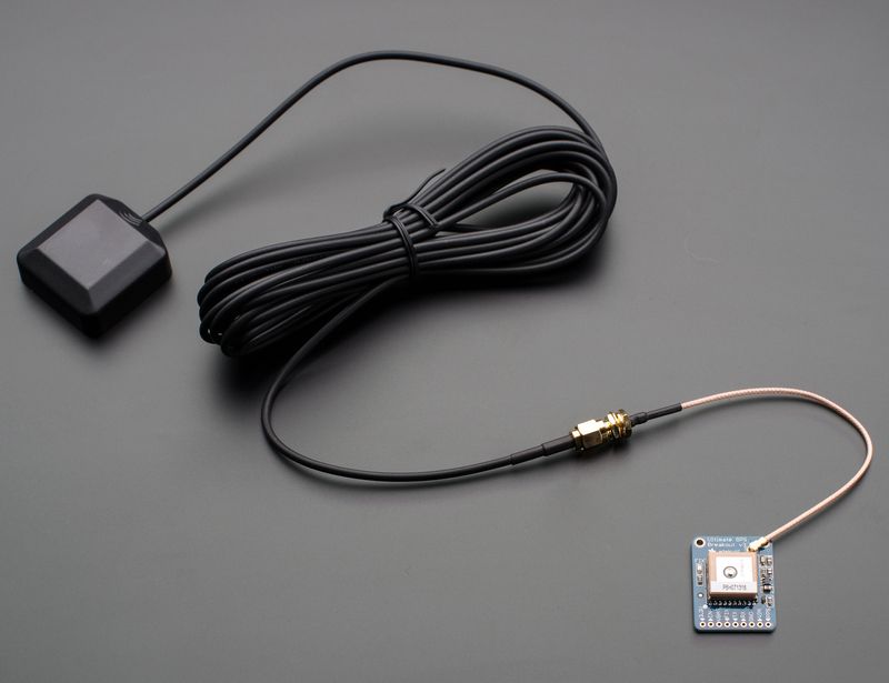
All Ultimate GPS modules have a built in patch antenna - this antenna provides -165 dBm sensitivity and is perfect for
many projects. However, if you want to place your project in a box, it might not be possible to have the antenna
pointing up, or it might be in a metal shield, or you may need more sensitivity. In these cases, you may want to use an
external active antenna. (http://adafru.it/960)
Active antennas draw current, so they do provide more gain but at a power cost. Check the antenna datasheet for
exactly how much current they draw - its usually around 10-20mA. (http://adafru.it/960)
Most GPS antennas use SMA connectors, which are popular and easy to use. However, an SMA connector would be
fairly big on the GPS breakout so we went with a uFL connector - which is lightweight, small and easy to manufacture. If
you don't need an external antenna it wont add significant weight or space but its easy to attach a uFL->SMA adapter
cable (http://adafru.it/851). Then connect the GPS antenna to the cable.
uFL connectors are small, delicate and are not rated for strain or tons of connections/disconnections. Once
you attach a uFL adapter use strain relief to avoid ripping off the uFL
The Ultimate GPS will automagically detect an external active antenna is attached and 'switch over' - you do not need
to send any commands
There is an output sentence that will tell you the status of the antenna. $PGTOP,11,x where x is the status number. If x
© Adafruit Industries https://learn.adafruit.com/adafruit-ultimate-gps Page 13 of 54is 3 that means it is using the external antenna. If x is 2 it's using the internal antenna and if x is 1 there was an antenna short or problem. On newer shields & modules, you'll need to tell the firmware you want to have this report output, you can do that by adding a gps.sendCommand(PGCMD_ANTENNA) around the same time you set the update rate/sentence output. © Adafruit Industries https://learn.adafruit.com/adafruit-ultimate-gps Page 14 of 54
Direct Computer Wiring
GPS modules are great in that the moment you turn them on, they'll start spitting out data, and trying to get a 'fix'
(location verification). Like pretty much every GPS in existence, the Adafruit Ultimate GPS uses TTL serial output to
send data so the best way to first test the GPS is to wire it directly to the computer via the TTL serial to USB converter
on an Arduino. You can also use an FTDI Friend or other TTL adapter but for this demonstration we'll use a classic
Arduino.
Leonardo Users: This tutorial step won't work with a Leonardo. Go on to the next step, "Arduino Wiring", but
refer back here for this discussion of the GPS data!
First, load a 'blank' sketch into the Arduino:
// this sketch will allow you to bypass the Atmega chip
// and connect the Ultimate GPS directly to the USB/Serial
// chip converter.
// Connect VIN to +5V
// Connect GND to Ground
// Connect GPS RX (data into GPS) to Digital 0
// Connect GPS TX (data out from GPS) to Digital 1
void setup() {}
void loop() {}
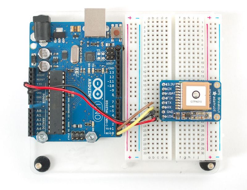
This is will free up the converter so you can directly wire and bypass the Arduino chip. Once you've uploaded this
sketch, wire the GPS as follows. Your module may look slightly different, but as long as you are connecting to the right
pin names, they all work identically for this part
© Adafruit Industries https://learn.adafruit.com/adafruit-ultimate-gps Page 15 of 54Now plug in the USB cable, and open up the serial monitor from the Arduino IDE and be sure to select 9600 baud in
the drop down. You should see text like the following:
This is the raw GPS "NMEA sentence" output from the module. There are a few different kinds of NMEA sentences, the
most common ones people use are the $GPRMC (Global Positioning RecommendedMinimum Coordinates or
something like that) and the $GPGGA sentences. These two provide the time, date, latitude, longitude, altitude,
estimated land speed, and fix type. Fix type indicates whether the GPS has locked onto the satellite data and received
enough data to determine the location (2D fix) or location+altitude (3D fix).
For more details about NMEA sentences and what data they contain, check out this site (https://adafru.it/kMb)
If you look at the data in the above window, you can see that there are a lot of commas, with no data in between them.
That's because this module is on my desk, indoors, and does not have a 'fix'. To get a fix, we need to put the module
outside.
GPS modules will always send data EVEN IF THEY DO NOT HAVE A FIX! In order to get 'valid' (not-blank)
data you must have the GPS module directly outside, with the square ceramic antenna pointing up with a
clear sky view. In ideal conditions, the module can get a fix in under 45 seconds. however depending on your
location, satellite configuration, solar flares, tall buildings nearby, RF noise, etc it may take up to half an hour
(or more) to get a fix! This does not mean your GPS module is broken, the GPS module will always work as
fast as it can to get a fix.
If you can get a really long USB cord (or attach a GPS antenna to the v3 modules) and stick the GPS out a window, so
its pointing at the sky, eventually the GPS will get a fix and the window data will change over to transmit valid data like
this:
© Adafruit Industries https://learn.adafruit.com/adafruit-ultimate-gps Page 16 of 54Look for the line that says $GPRMC,194509.000,A,4042.6142,N,07400.4168,W,2.03,221.11,160412,,,A*77
This line is called the RMC (Recommended Minimum) sentence and has pretty much all of the most useful data. Each
chunk of data is separated by a comma.
The first part 194509.000 is the current time GMT (Greenwich Mean Time). The first two numbers 19 indicate the hour
(1900h, otherwise known as 7pm) the next two are the minute, the next two are the seconds and finally the
milliseconds. So the time when this screenshot was taken is 7:45 pm and 9 seconds. The GPS does not know what
time zone you are in, or about "daylight savings" so you will have to do the calculation to turn GMT into your timezone
The second part is the 'status code', if it is a V that means the data is Void (invalid). If it is an A that means its Active
(the GPS could get a lock/fix)
The next 4 pieces of data are the geolocation data. According to the GPS, my location is 4042.6142,N (Latitude 40
degrees, 42.6142 decimal minutes North) & 07400.4168,W. (Longitude 74 degrees, 0.4168 decimal minutes West) To
look at this location in Google maps, type +40 42.6142', -74 00.4168' into the google maps search
box (https://adafru.it/aMl) . Unfortunately gmaps requires you to use +/- instead of NSWE notation. N and E are positive,
S and W are negative.
People often get confused because the GPS is working but is "5 miles off" - this is because they are not
parsing the lat/long data correctly. Despite appearances, the geolocation data is NOT in decimal degrees. It
is in degrees and minutes in the following format: Latitude: DDMM.MMMM (The first two characters are the
degrees.) Longitude: DDDMM.MMMM (The first three characters are the degrees.)
The next data is the ground speed in knots. We're going 2.03 knots
After that is the tracking angle, this is meant to approximate what 'compass' direction we're heading at based on our
past travel
The one after that is 160412 which is the current date (16th of April, 2012).
Finally there is the *XX data which is used as a data transfer checksum
Once you get a fix using your GPS module, verify your location with google maps (or some other mapping software).
Remember that GPS is often only accurate to 5-10 meters and worse if you're indoors or surrounded by tall buildings.
© Adafruit Industries https://learn.adafruit.com/adafruit-ultimate-gps Page 17 of 54Breakout Arduino Wiring
Once you've gotten the GPS module tested with direct wiring, we can go forward and wire it up to a microcontroller.
We'll be using an Arduino but you can adapt our code to any other microcontroller that can receive TTL serial at 9600
baud.
Connect VIN to +5V, GND to Ground, RX to digital 2 and TX to digital 3.
Next up, download the Adafruit GPS library. This library does a lot of the 'heavy lifting' required for receiving data from
GPS modules, such as reading the streaming data in a background interrupt and auto-magically parsing it. To
download it, visit the GitHub repository (https://adafru.it/aMm) or just click below
https://adafru.it/emg
https://adafru.it/emg
rename the uncompressed folder Adafruit_GPS. Check that the Adafruit_GPS folder contains Adafruit_GPS.cpp and
Adafruit_GPS.h
Move Adafruit_GPS to your Arduino/Libraries folder and restart the Arduino IDE. Library installation is a frequent
stumbling block…if you need assistance, our All About Arduino Libraries (https://adafru.it/dit) guide spells it out in detail!
Leonardo & Micro Users: We have special example sketches in the Adafruit_GPS library that work with the
Micro/Leo!
Open up the File→Examples→Adafruit_GPS→echo sketch and upload it to the Arduino. Then open up the serial
monitor. This sketch simply reads data from the software serial port (pins 2&3) and outputs that to the hardware serial
port connected to USB.
© Adafruit Industries https://learn.adafruit.com/adafruit-ultimate-gps Page 18 of 54Open up the Arduino IDE Serial Console and make sure to set the Serial baud rate to 115200 You can configure the GPS output you see by commenting/uncommenting lines in the setup() procedure. For example, we can ask the GPS to send different sentences, and change how often it sends data. 10 Hz (10 times a second) is the max speed, and is a lot of data. You may not be able to output "all data" at that speed because the 9600 baud rate is not fast enough. // You can adjust which sentences to have the module emit, below // uncomment this line to turn on RMC (recommended minimum) and GGA (fix data) including altitude GPS.sendCommand(PMTK_SET_NMEA_OUTPUT_RMCGGA); // uncomment this line to turn on only the "minimum recommended" data for high update rates! //GPS.sendCommand(PMTK_SET_NMEA_OUTPUT_RMCONLY); // uncomment this line to turn on all the available data - for 9600 baud you'll want 1 Hz rate //GPS.sendCommand(PMTK_SET_NMEA_OUTPUT_ALLDATA); // Set the update rate // 1 Hz update rate //GPS.sendCommand(PMTK_SET_NMEA_UPDATE_1HZ); // 5 Hz update rate- for 9600 baud you'll have to set the output to RMC or RMCGGA only (see above) GPS.sendCommand(PMTK_SET_NMEA_UPDATE_5HZ); // 10 Hz update rate - for 9600 baud you'll have to set the output to RMC only (see above) //GPS.sendCommand(PMTK_SET_NMEA_UPDATE_10HZ); In general, we find that most projects only need the RMC and GGA NMEA's so you don't need ALLDATA unless you have some need to know satellite locations. © Adafruit Industries https://learn.adafruit.com/adafruit-ultimate-gps Page 19 of 54
Breakout Arduino Parsing
Since all GPS's output NMEA sentences and often for our projects we need to extract the actual data from them, we've
simplified the task tremendously when using the Adafruit GPS library. By having the library read, store and parse the
data in a background interrupt it becomes trivial to query the library and get the latest updated information without any
icky parsing work.

Open up the File→Examples→Adafruit_GPS→parsing sketch and upload it to the Arduino. Then open up the serial
monitor.

In this sketch, we call GPS.read() constantly in the main loop (if you can, get this to run once a millisecond in an
interrupt). Then in the main loop we can ask if a new chunk of data has been received by
calling GPS.newNMEAreceived(), if this returns true then we can ask the library to parse that data
with GPS.parse(GPS.lastNMEA()).

We do have to keep querying and parsing in the main loop - its not possible to do this in an interrupt because then
we'd be dropping GPS data by accident.

Once data is parsed, we can just ask for data from the library like GPS.day, GPS.month and GPS.year for the current
date. GPS.fix will be 1 if there is a fix, 0 if there is none. If we have a fix then we can ask
for GPS.latitude, GPS.longitude, GPS.speed (in knots, not mph or k/hr!), GPS.angle, GPS.altitude (in centimeters)
and GPS.satellites (number of satellites)

This should make it much easier to have location-based projects. We suggest keeping the update rate at 1Hz and
request that the GPS only output RMC and GGA as the parser does not keep track of other data anyways.

 © Adafruit Industries                 https://learn.adafruit.com/adafruit-ultimate-gps                      Page 20 of 54
CircuitPython & Python
Setup
You can easily use a GPS module with Python or CircuitPython code in addition to Arduino. Python code is well suited
for parsing and processing the text output from GPS modules, and this Adafruit CircuitPython
GPS (https://adafru.it/BuR) module handles most of the work for you!

CircuitPython MicroController Wiring
First make sure to wire up the GPS module to your CircuitPython board so that the hardware UART pins are used.
Here's an example with the Metro M0 Express:

                                                       Board 5V or 3.3V to GPS module
                                                       VIN.
                                                       Board GND to GPS module GND.
                                                       Board serial TX to GPS module RX.
                                                       Board serial RX to GPS module TX.

Python Computer Wiring
Since there's dozens of Linux computers/boards you can use we will show wiring for Raspberry Pi. For other platforms,
please visit the guide for CircuitPython on Linux to see whether your platform is supported (https://adafru.it/BSN).

Here you have two options: An external USB-to-serial converter, or the built-in UART on the Pi's TX/RX pins. Here's an
example of wiring up the USB-to-serial converter (https://adafru.it/dDd):

                                                                    GPS Vin to USB 5V or 3V (red wire on USB
                                                                    console cable)
                                                                    GPS Ground to USB Ground (black wire)
                                                                    GPS RX to USB TX (green wire)
                                                                    GPS TX to USB RX (white wire)

 © Adafruit Industries               https://learn.adafruit.com/adafruit-ultimate-gps                   Page 21 of 54
For single board computers other than the Raspberry Pi, the serial port may be tied to the console or not be
available to the user. Please see the board documentation to see how the serial port may be used
You can also skip the USB console cable, and just plug
a Micro B cable directly from your computer to the
Ultimate GPS USB
Here's an example using the Pi's built-in UART:
GPS Vin to 3.3V (red wire)
GPS Ground to Ground (black wire)
GPS RX to TX (green wire)
GPS TX to RX (white wire)
If you want to use the built-in UART, you'll need to disable the serial console and enable the serial port hardware in
raspi-config. See the UART/Serial section of the CircuitPython on Raspberry Pi guide (https://adafru.it/CEk) for detailed
instructions on how to do this.
CircuitPython Installation of GPS Library
Next you'll need to install the Adafruit CircuitPython GPS (https://adafru.it/BuR) library on your CircuitPython
board. Remember this module is for Adafruit CircuitPython firmware and not MicroPython.org firmware!
First make sure you are running the latest version of Adafruit CircuitPython (https://adafru.it/tBa) for your board.
Next you'll need to install the necessary libraries to use the hardware. Carefully follow the steps to find and install these
libraries from Adafruit's CircuitPython library bundle (https://adafru.it/zdx). For example, the Circuit Playground Express
guide has a great page on how to install the library bundle (https://adafru.it/Bf2) for both Express and non-Express
boards.
Remember for non-Express boards like the Trinket M0, Gemma M0, and Feather/Metro M0 basic, you'll need to
© Adafruit Industries https://learn.adafruit.com/adafruit-ultimate-gps Page 22 of 54manually install the necessary libraries from the bundle:
adafruit_gps.mpy
You can also download the adafruit_gps.mpy file from the Adafruit CircuitPython GPS releases
page (https://adafru.it/BuS).
Before continuing make sure your board's lib folder has the adafruit_gps.mpy file copied over.
Python Installation of GPS Library
You'll need to install the Adafruit_Blinka library that provides the CircuitPython support in Python. This may require
verifying you are running Python 3. Since each platform is a little different, and Linux changes often, please visit the
CircuitPython on Linux guide to get your computer ready (https://adafru.it/BSN)!
Once that's done, from your command line run the following command:
sudo pip3 install adafruit-circuitpython-gps
© Adafruit Industries https://learn.adafruit.com/adafruit-ultimate-gps Page 23 of 54CircuitPython & Python UART
Usage
To demonstrate the usage of the GPS module in CircuitPython using UART, let's look at a complete program example,
the gps_simpletest.py file from the module's examples.
CircuitPython Microcontroller
With a CircuitPython microcontroller, save this file as code.py on your board, then open the serial console to see its
output.
Linux/Computer/Raspberry Pi with Python
If you're running gps_simpletest.py on the Raspberry Pi (or any computer), you'll have to make some changes.
On the Raspberry Pi, comment out the uart = busio(...) line, and uncomment the import serial and uart =
serial.Serial(...) lines, changing /dev/ttyUSB0 to the appropriate serial port. Now you can run the program with the
following command:
python3 gps_simpletest.py
Example Parsing Code
# Simple GPS module demonstration.
# Will wait for a fix and print a message every second with the current location
# and other details.
import time
import board
import busio
import adafruit_gps
# Create a serial connection for the GPS connection using default speed and
# a slightly higher timeout (GPS modules typically update once a second).
# These are the defaults you should use for the GPS FeatherWing.
# For other boards set RX = GPS module TX, and TX = GPS module RX pins.
uart = busio.UART(board.TX, board.RX, baudrate=9600, timeout=10)
# for a computer, use the pyserial library for uart access
# import serial
# uart = serial.Serial("/dev/ttyUSB0", baudrate=9600, timeout=10)
# If using I2C, we'll create an I2C interface to talk to using default pins
# i2c = board.I2C()
# Create a GPS module instance.
gps = adafruit_gps.GPS(uart, debug=False) # Use UART/pyserial
# gps = adafruit_gps.GPS_GtopI2C(i2c, debug=False) # Use I2C interface
# Initialize the GPS module by changing what data it sends and at what rate.
# These are NMEA extensions for PMTK_314_SET_NMEA_OUTPUT and
# PMTK_220_SET_NMEA_UPDATERATE but you can send anything from here to adjust
© Adafruit Industries https://learn.adafruit.com/adafruit-ultimate-gps Page 24 of 54# PMTK_220_SET_NMEA_UPDATERATE but you can send anything from here to adjust
# the GPS module behavior:
# https://cdn-shop.adafruit.com/datasheets/PMTK_A11.pdf
# Turn on the basic GGA and RMC info (what you typically want)
gps.send_command(b"PMTK314,0,1,0,1,0,0,0,0,0,0,0,0,0,0,0,0,0,0,0")
# Turn on just minimum info (RMC only, location):
# gps.send_command(b'PMTK314,0,1,0,0,0,0,0,0,0,0,0,0,0,0,0,0,0,0,0')
# Turn off everything:
# gps.send_command(b'PMTK314,0,0,0,0,0,0,0,0,0,0,0,0,0,0,0,0,0,0,0')
# Tuen on everything (not all of it is parsed!)
# gps.send_command(b'PMTK314,1,1,1,1,1,1,0,0,0,0,0,0,0,0,0,0,0,0,0')
# Set update rate to once a second (1hz) which is what you typically want.
gps.send_command(b"PMTK220,1000")
# Or decrease to once every two seconds by doubling the millisecond value.
# Be sure to also increase your UART timeout above!
# gps.send_command(b'PMTK220,2000')
# You can also speed up the rate, but don't go too fast or else you can lose
# data during parsing. This would be twice a second (2hz, 500ms delay):
# gps.send_command(b'PMTK220,500')
# Main loop runs forever printing the location, etc. every second.
last_print = time.monotonic()
while True:
# Make sure to call gps.update() every loop iteration and at least twice
# as fast as data comes from the GPS unit (usually every second).
# This returns a bool that's true if it parsed new data (you can ignore it
# though if you don't care and instead look at the has_fix property).
gps.update()
# Every second print out current location details if there's a fix.
current = time.monotonic()
if current - last_print >= 1.0:
last_print = current
if not gps.has_fix:
# Try again if we don't have a fix yet.
print("Waiting for fix...")
continue
# We have a fix! (gps.has_fix is true)
# Print out details about the fix like location, date, etc.
print("=" * 40) # Print a separator line.
print(
"Fix timestamp: {}/{}/{} {:02}:{:02}:{:02}".format(
gps.timestamp_utc.tm_mon, # Grab parts of the time from the
gps.timestamp_utc.tm_mday, # struct_time object that holds
gps.timestamp_utc.tm_year, # the fix time. Note you might
gps.timestamp_utc.tm_hour, # not get all data like year, day,
gps.timestamp_utc.tm_min, # month!
gps.timestamp_utc.tm_sec,
)
)
print("Latitude: {0:.6f} degrees".format(gps.latitude))
print("Longitude: {0:.6f} degrees".format(gps.longitude))
print("Fix quality: {}".format(gps.fix_quality))
# Some attributes beyond latitude, longitude and timestamp are optional
# and might not be present. Check if they're None before trying to use!
if gps.satellites is not None:
print("# satellites: {}".format(gps.satellites))
if gps.altitude_m is not None:
print("Altitude: {} meters".format(gps.altitude_m))
© Adafruit Industries https://learn.adafruit.com/adafruit-ultimate-gps Page 25 of 54if gps.speed_knots is not None:
print("Speed: {} knots".format(gps.speed_knots))
if gps.track_angle_deg is not None:
print("Track angle: {} degrees".format(gps.track_angle_deg))
if gps.horizontal_dilution is not None:
print("Horizontal dilution: {}".format(gps.horizontal_dilution))
if gps.height_geoid is not None:
print("Height geo ID: {} meters".format(gps.height_geoid))
When the code runs it will print a message every second, either an update that it's still waiting for a GPS fix:
Note: Due to the antenna being built in, the PA1010D Mini GPS module may need a more unobstructed view of the sky
than other GPS modules with eternal antennae. With any GPS module, if you are having trouble getting a fix, try moving
it to a more ideal location.
Once a fix has been established, it will print details about the current location and other GPS data:
Let's look at the code in a bit more detail to understand how it works. First the example needs to import a few
modules like the built-in busio and board modules that access serial ports and other hardware:
import board
import busio
import time
Next the GPS module is imported:
import adafruit_gps
Now a serial UART (https://adafru.it/BuT) is created and connected to the serial port pins the GPS module will use, this
© Adafruit Industries https://learn.adafruit.com/adafruit-ultimate-gps Page 26 of 54is the low level transport layer to communicate with the GPS module:
# Define RX and TX pins for the board's serial port connected to the GPS.
# These are the defaults you should use for the GPS FeatherWing.
# For other boards set RX = GPS module TX, and TX = GPS module RX pins.
RX = board.RX
TX = board.TX
# Create a serial connection for the GPS connection using default speed and
# a slightly higher timeout (GPS modules typically update once a second).
uart = busio.UART(TX, RX, baudrate=9600, timeout=3000)
# for a computer, use the pyserial library for uart access
#import serial
#uart = serial.Serial("/dev/ttyUSB0", baudrate=9600, timeout=3000)
Once a UART object is available with a connected GPS module you can create an instance of the GPS parsing class.
You need to pass this class the UART instance and it will internally read new data from the GPS module connected to
it:
gps = adafruit_gps.GPS(uart)
GPS Example Code Explained
Before reading GPS data the example configures the module by sending some custom NMEA GPS
commands (https://adafru.it/qif) that adjust the amount and rate of data. Read the comments to see some options for
adjust the rate and amount of data, but typically you want the defaults of core location info at a rate of once a second:
# Initialize the GPS module by changing what data it sends and at what rate.
# These are NMEA extensions for PMTK_314_SET_NMEA_OUTPUT and
# PMTK_220_SET_NMEA_UPDATERATE but you can send anything from here to adjust
# the GPS module behavior:
# https://cdn-shop.adafruit.com/datasheets/PMTK_A11.pdf
# Turn on the basic GGA and RMC info (what you typically want)
gps.send_command(b'PMTK314,0,1,0,1,0,0,0,0,0,0,0,0,0,0,0,0,0,0,0')
# Turn on just minimum info (RMC only, location):
#gps.send_command(b'PMTK314,0,1,0,0,0,0,0,0,0,0,0,0,0,0,0,0,0,0,0')
# Turn off everything:
#gps.send_command(b'PMTK314,0,0,0,0,0,0,0,0,0,0,0,0,0,0,0,0,0,0,0')
# Tuen on everything (not all of it is parsed!)
#gps.send_command(b'PMTK314,1,1,1,1,1,1,0,0,0,0,0,0,0,0,0,0,0,0,0')
# Set update rate to once a second (1hz) which is what you typically want.
gps.send_command(b'PMTK220,1000')
# Or decrease to once every two seconds by doubling the millisecond value.
# Be sure to also increase your UART timeout above!
#gps.send_command(b'PMTK220,2000')
# You can also speed up the rate, but don't go too fast or else you can lose
# data during parsing. This would be twice a second (2hz, 500ms delay):
#gps.send_command(b'PMTK220,500')
If you want you can send other custom commands to the GPS module with the send_command function shown above.
© Adafruit Industries https://learn.adafruit.com/adafruit-ultimate-gps Page 27 of 54You don't need to worry about adding a NMEA checksum to your command either, the function will do this
automatically (or not, set add_checksum=False as a parameter and it will skip the checksum addition).
Now we can jump into a main loop that continually updates data from the GPS module and prints out status. The most
important part of this loop is calling the GPS update function:
# Make sure to call gps.update() every loop iteration and at least twice
# as fast as data comes from the GPS unit (usually every second).
# This returns a bool that's true if it parsed new data (you can ignore it
# though if you don't care and instead look at the has_fix property).
gps.update()
Like the comments mention, you must call update every loop iteration and ideally multiple times a second. Each time
you call update , it allows the GPS library code to read new data from the GPS module and update its state. Since the
GPS module is always sending data you have to be careful to constantly read data or else you might start to lose data
as buffers are filled.
You can check the has_fix property to see if the module has a GPS location fix, and if so there are a host of attributes
to read like latitude and longitude (available in degrees):
if not gps.has_fix:
# Try again if we don't have a fix yet.
print('Waiting for fix...')
continue
# We have a fix! (gps.has_fix is true)
# Print out details about the fix like location, date, etc.
print('=' * 40) # Print a separator line.
print('Fix timestamp: {}/{}/{} {:02}:{:02}:{:02}'.format(
gps.timestamp_utc.tm_mon, # Grab parts of the time from the
gps.timestamp_utc.tm_mday, # struct_time object that holds
gps.timestamp_utc.tm_year, # the fix time. Note you might
gps.timestamp_utc.tm_hour, # not get all data like year, day,
gps.timestamp_utc.tm_min, # month!
gps.timestamp_utc.tm_sec))
print('Latitude: {} degrees'.format(gps.latitude))
print('Longitude: {} degrees'.format(gps.longitude))
print('Fix quality: {}'.format(gps.fix_quality))
# Some attributes beyond latitude, longitude and timestamp are optional
# and might not be present. Check if they're None before trying to use!
if gps.satellites is not None:
print('# satellites: {}'.format(gps.satellites))
if gps.altitude_m is not None:
print('Altitude: {} meters'.format(gps.altitude_m))
if gps.track_angle_deg is not None:
print('Speed: {} knots'.format(gps.speed_knots))
if gps.track_angle_deg is not None:
print('Track angle: {} degrees'.format(gps.track_angle_deg))
if gps.horizontal_dilution is not None:
print('Horizontal dilution: {}'.format(gps.horizontal_dilution))
if gps.height_geoid is not None:
Notice some of the attributes like altitude_m are checked to be None before reading. This is a smart check to put in
your code, because those attributes are sometimes not sent by a GPS module. If an attribute isn't sent by the module it
will be given a None /null value and attempting to print or read it in Python will fail. The core attributes of
© Adafruit Industries https://learn.adafruit.com/adafruit-ultimate-gps Page 28 of 54latitude , longitude , and timestamp are usually always available (if you're using the example as-is) but they might not be if you turn off those outputs with a custom NMEA command! That's all there is to reading GPS location with CircuitPython code! © Adafruit Industries https://learn.adafruit.com/adafruit-ultimate-gps Page 29 of 54
CircuitPython Datalogging
Datalogging Example
Another handy task with GPS is logging all the raw output of the GPS module to a file. This is useful if you're importing
the GPS data into a tool like Google Earth which can process raw NMEA sentences. You can perform this datalogging
very easily with CircuitPython.

To store data you'll need to choose one of two options:

     Wire up a SD card holder to your board's SPI bus, or use a board with SD card holder built-in like the Feather M0
     Adalogger (https://adafru.it/weP). This is the recommended approach as it gives you a lot of space to store data
     and you can easily copy the data to your computer from the card.
     Store data in your board's internal filesystem. This requires a little more setup but allows you to save to a file on
     the internal filesystem of your CircuitPython board, right next to where code and other data files live. This is more
     limited because depending on your board you might only have a few kilobytes or megabytes of space available
     and GPS sentences will quickly add up (easily filling multiple megabytes within a few hours of logging).

Install SD Card Library
If you're storing data on a SD card you must ensure the SD card is wired to your board and you have installed the
Adafruit SD card library. Luckily there's an entire guide to follow to learn about this process of connecting a SD card
and installing the necessary library (https://adafru.it/BuU). Be sure to carefully follow the guide so the card is
connected, library installed, and you can confirm you're able to manually write data to the card from the Python prompt.

Enable Internal Filesystem Writes
If you're storing data on the internal filesystem you must carefully follow the steps in the CPU temperature logging
guide to enable writing to internal storage (https://adafru.it/BuV). If you're writing to a SD card skip these steps and
move on to look at the datalogging code below. Edit the boot.py on your board (creating it if it doesn't exist) and add
these lines:

 import digitalio
 import board
 import storage

 switch = digitalio.DigitalInOut(board.D5)
 switch.direction = digitalio.Direction.INPUT
 switch.pull = digitalio.Pull.UP

 # If the D5 is connected to ground with a wire
 # you can edit files over the USB drive again.
 storage.remount("/", not switch.value)

Remember once you remount("/") you cannot edit code over the USB drive anymore! That means you can't
edit boot.py which is a bit of a conundrum. So we configure the boot.py to selectively mount the internal filesystem as
writable based on a switch or even just alligator clip connected to ground. Like the CPU temperature guide
shows (https://adafru.it/BuV) . In this example we're using D5 but select any available pin.

This code will look at the D5 digital input when the board starts up and if it's connected to ground (use an alligator clip
or wire, for example, to connect from D5 to board ground) it will disable internal filesystem writes and allow you to edit

 © Adafruit Industries                https://learn.adafruit.com/adafruit-ultimate-gps                      Page 30 of 54
code over the USB drive as normal. Remove the alligator clip, reset the board, and the boot.py will switch to mounting
the internal filesystem as writable so you can log images to it again (but not write any code!).
Remember when you enable USB drive writes (by connecting D5 to ground at startup) you cannot write files to the
internal filesystem and any code in your main.py that attempts to do so (like the example below) will fail. Keep this in
mind as you edit code--once you modify code you need to remove the alligator clip, reset the board to re-
enable internal filesystem writes, and then watch the output of your program.
If you ever get stuck, you can follow the steps mentioned in https://learn.adafruit.com/cpu-temperature-
logging-with-circuit-python/writing-to-the-filesystem to remove boot.py from the REPL if you need to go back
and edit code!
Datalogging Example Code
The GPS library examples have a datalogging.py file you can edit and save as a main.py on your board:
# Simple GPS datalogging demonstration.
# This example uses the GPS library and to read raw NMEA sentences
# over I2C or UART from the GPS unit and dumps them to a file on an SD card
# (recommended), microcontroller internal storage (be careful as only a few
# kilobytes are available), or to a filesystem.
# If you are using a microcontroller, before writing to internal storage you
# MUST carefully follow the steps in this guide to enable writes to the
# internal filesystem:
# https://learn.adafruit.com/adafruit-ultimate-gps-featherwing/circuitpython-library
import board
import busio
import adafruit_gps
# Path to the file to log GPS data. By default this will be appended to
# which means new lines are added at the end and all old data is kept.
# Change this path to point at internal storage (like '/gps.txt') or SD
# card mounted storage ('/sd/gps.txt') as desired.
LOG_FILE = "gps.txt" # Example for writing to internal path gps.txt
# File more for opening the log file. Mode 'ab' means append or add new lines
# to the end of the file rather than erasing it and starting over. If you'd
# like to erase the file and start clean each time use the value 'wb' instead.
LOG_MODE = "ab"
# If writing to SD card on a microcontroller customize and uncomment these
# lines to import the necessary library and initialize the SD card:
# NOT for use with a single board computer like Raspberry Pi!
"""
import adafruit_sdcard
import digitalio
import storage
SD_CS_PIN = board.D10 # CS for SD card using Adalogger Featherwing
spi = busio.SPI(board.SCK, MOSI=board.MOSI, MISO=board.MISO)
sd_cs = digitalio.DigitalInOut(SD_CS_PIN)
sdcard = adafruit_sdcard.SDCard(spi, sd_cs)
vfs = storage.VfsFat(sdcard)
storage.mount(vfs, '/sd') # Mount SD card under '/sd' path in filesystem.
LOG_FILE = '/sd/gps.txt' # Example for writing to SD card path /sd/gps.txt
"""
© Adafruit Industries https://learn.adafruit.com/adafruit-ultimate-gps Page 31 of 54"""
# Create a serial connection for the GPS connection using default speed and
# a slightly higher timeout (GPS modules typically update once a second).
# These are the defaults you should use for the GPS FeatherWing.
# For other boards set RX = GPS module TX, and TX = GPS module RX pins.
uart = busio.UART(board.TX, board.RX, baudrate=9600, timeout=10)
# If using a USB/Serial converter, use pyserial and update the serial
# port name to match the serial connection for the GPS!
# import serial
# uart = serial.Serial("/dev/ttyUSB0", baudrate=9600, timeout=10)
# If using I2C, we'll create an I2C interface to talk to using default pins
# i2c = board.I2C()
# Create a GPS module instance.
gps = adafruit_gps.GPS(uart) # Use UART/pyserial
# gps = adafruit_gps.GPS_GtopI2C(i2c) # Use I2C interface
# Main loop just reads data from the GPS module and writes it back out to
# the output file while also printing to serial output.
with open(LOG_FILE, LOG_MODE) as outfile:
while True:
sentence = gps.readline()
if not sentence:
continue
print(str(sentence, "ascii").strip())
outfile.write(sentence)
outfile.flush()
By default this example expects to log GPS NMEA sentences to a file on the internal storage system at /gps.txt. New
sentences will be appended to the end of the file every time the example starts running.
If you'd like to instead write to the SD card take note to uncomment the appropriate lines mentioned in the comments:
# Path to the file to log GPS data. By default this will be appended to
# which means new lines are added at the end and all old data is kept.
# Change this path to point at internal storage (like '/gps.txt') or SD
# card mounted storage ('/sd/gps.txt') as desired.
#LOG_FILE = '/gps.txt' # Example for writing to internal path /gps.txt
LOG_FILE = '/sd/gps.txt' # Example for writing to SD card path /sd/gps.txt
And further below:
Should all be uncommented and look as above. This will configure the code to write GPS NMEA data to
the /sd/gps.txt file, appending new data to the end of the file.
Once the example is running as a main.py on your board open the serial REPL and you should see the raw NMEA
sentences printed out:
© Adafruit Industries https://learn.adafruit.com/adafruit-ultimate-gps Page 32 of 54Check the gps.txt file (either under the root or /sd path depending on how you setup the example) in a text editor and you'll see the same raw NMEA sentences: Awesome! That's all there is to basic datalogging of NMEA sentences with a GPS module and CircuitPython! © Adafruit Industries https://learn.adafruit.com/adafruit-ultimate-gps Page 33 of 54
Python Docs
Python Docs (https://adafru.it/C4M)

 © Adafruit Industries                https://learn.adafruit.com/adafruit-ultimate-gps   Page 34 of 54
Built In Logging
One of the nice things about the MTK3339 is the built in data-logger. This basic data-logging capability can store date,
time, latitude, longitude and altitude data into a 64K flash chip inside. Its not a high resolution logger - it only logs once
every 15 seconds when there is a fix - but for 99% of projects that want to track location, this can be a great low power
way to log data - no SD card or other EEPROM required! It can store up to 16 hours of data.

The GPS module does require a microcontroller to 'kick start' the logger by requesting it to start. If power is lost it will
require another 'kick' to start. If you already have some data in the FLASH, a new trace will be created (so you wont
lose old data) and if you run out of space it will simply halt and not overwrite old data. Despite this annoyance, its still a
very nice extra and we have some library support to help you use it

For more details check out the LOCUS (built-in-datalogging system) user guide (https://adafru.it/uoc)

First, we should try getting the logger to run.Open up the File→Examples→Adafruit_GPS→locus_start sketch. This will
demonstrate how to start the logger (called LOCUS)

The key part is here:

 Serial.print("STARTING LOGGING....");
   if (GPS.LOCUS_StartLogger())
     Serial.println(" STARTED!");
   else
     Serial.println(" no response :(");
   delay(1000);

You should start the logger and then check the response:

Logging Status

Once you've seen that the GPS is OK with logging, you can load up the status sketch which will also give you more
data. Upload File→Examples→Adafruit_GPS→locus_status

 © Adafruit Industries                 https://learn.adafruit.com/adafruit-ultimate-gps                        Page 35 of 54
This output gives you some more information. the first entry is the Log #. This is how many log traces are in the
memory. Every time you start and save data, a new log is made. Full Stop means that once the logger has run out of
memory it will stop. Next the output indicates that we are logging only during fix data and at set intervals, with an
interval delay of 15 seconds. We are not logging based on distance or speed. The current status is LOGGING (active),
there's also the number of records we've stored. Each record is a timestamped location. We log once every 15
seconds, you can see the records increment from 344 to 345 here. Lastly, we can see how much of the internal flash
storage is used, only 4% at this point
In real use, you'll probably want to start the loggging and then have your microcontroller go to sleep to reserve power,
waking up once in a while to check up on the logging status.
Downloading Data
Finally, once we're done logging we need to extract the data. To do this we need to first get the raw data out of the
FLASH and then decode the sentences. UploadFile→Examples→Adafruit_GPS→locus_dump to the Arduino and open
up the serial monitor
PLEASE NOTE: Asking the Arduino, with 2K RAM buffer to handle 64KB of FLASH data and spit it out from
the GPS can sometimes over-tax the processor. If you are having hiccups, check the GPS tool instructions
below
© Adafruit Industries https://learn.adafruit.com/adafruit-ultimate-gps Page 36 of 54Copy and paste all the text after the —-'s (starting with $PMTKLOX,0,86*67 and ending with $PMTK001,622,3*36) then paste it into the box located on this page (https://adafru.it/cFg) OR you can try this python tool that don has kindly donated (https://adafru.it/emj) to the community! Using the GPS Tool If you are having difficulty with the Arduino/javascript tool, you can also try using the GPS tool. The tool runs only under Windows but it is very powerful. Connect the GPS module to an Arduino (connected with the Direct Wiring example) (https://adafru.it/aOP) , FTDI adapter or other TTL converter and download the GPS Tool (https://adafru.it/uod) - connect to the GPS via the COM port of the Arduino/FTDI/TTL cable. You can then query, dump and delete the log memory © Adafruit Industries https://learn.adafruit.com/adafruit-ultimate-gps Page 37 of 54
LOCUS Parser
LOCUS Parser (https://adafru.it/cFg)

 © Adafruit Industries                 https://learn.adafruit.com/adafruit-ultimate-gps   Page 38 of 54
Resources
Datasheets
      MTK3329/MTK3339 command set sheet (https://adafru.it/e7A) for changing the fix data rate, baud rate, sentence
      outputs, etc!
      PMTK 'complete' data (https://adafru.it/uoe)sheet (like the above but with even more commands)
      Datasheet for the PA6B (MTK3329) GPS module itself (https://adafru.it/aMo)
      Datasheet for the PA6C (MTK3339) GPS module itself (https://adafru.it/aMp)
      Datasheet for the PA6H (MTK3339) GPS module itself (https://adafru.it/aPO)
      MT3339 GPS PC Tool (windows only) (https://adafru.it/uof) and the PC Tool manual (https://adafru.it/uoA)
      Sample code and spec sheet for the LOCUS built-in logger (https://adafru.it/aTi)
      LOCUS (built-in-datalogging system) user guide (https://adafru.it/uoc)
      Mini GPS tool (windows only) (https://adafru.it/aMs)

More reading:
      Trimble's GPS tutorial (https://adafru.it/emh)
      Garmin's GPS tutorial (https://adafru.it/aMv)

Adafruit GPS Library for Arduino
https://github.com/adafruit/Adafruit-GPS-Library/ (https://adafru.it/emi)

EPO files for AGPS use
Data format for EPO files (https://adafru.it/uoB)

                                                       https://adafru.it/eb1
                                                       https://adafru.it/eb1

 © Adafruit Industries                 https://learn.adafruit.com/adafruit-ultimate-gps              Page 39 of 54
F.A.Q. Can the Ultimate GPS be used for High Altitude? How can I know? Modules shipped in 2013+ (and many in the later half of 2012) have firmware that has been tested by simulation at the GPS factory at 40km. You can tell what firmware you have by sending the firmware query command $PMTK605*31 (you can use the echo demo to send custom sentences to your GPS) If your module replies with AXN_2.10_3339_2012072601 5223 that means you have version #5223 which is the 40Km-supported firmware version. If the number is higher then 5223 then its even more recent, and should include the 40Km support as well HOWEVER these modules are not specifically designed for high-altitude balloon use. People have used them successfully but since we (at Adafruit) have not personally tested them for hi-alt use, we do not in any way guarantee they are suitable for high altitude use. Please do not ask us to 'prove' that they are good for high altitude use, we do not have any way to do so If you want to measure high altitude with a GPS, please find a module that can promise/guarantee high altitude functionality © Adafruit Industries https://learn.adafruit.com/adafruit-ultimate-gps Page 40 of 54
Is the Ultimate GPS affected by the 2019 Week Rollover issue?

The ultimate GPS (all firmware versions from 20110922_GTOP_EVK01_A2.10 and higher - any sold after 2011) have
been tested to work fine through 2019.

They do not pass the 2038 rollover test, so you may need to update the firmware between now and 2038. This
does not affect the 2019 rollover (there's one every ~20 years)

© Adafruit Industries            https://learn.adafruit.com/adafruit-ultimate-gps                Page 41 of 54
OK I want the latest firmware!

Here is the binary of the 5632 firmware, you can use this tool to upload it using an FTDI or USB-TTL cable (or direct
wiring with FTDI). We do not have a tutorial for updating the firmware, if you update the firmware and somehow brick
the GPS, we do not offer replacements! Keep this in mind before performing the update process!

© Adafruit Industries              https://learn.adafruit.com/adafruit-ultimate-gps                   Page 42 of 54
I've adapted the example code and my GPS NMEA sentences are all garbled and incomplete!

We use SoftwareSerial to read from the GPS, which is 'bitbang' UART support. It isn't super great on the Arduino and
does work but adding too many delay()s and not calling the GPS data parser enough will cause it to choke on data.

If you are using Leonardo (or Micro/Flora/ATmega32u4) or Mega, consider using a HardwareSerial port instead of
SoftwareSerial!

© Adafruit Industries             https://learn.adafruit.com/adafruit-ultimate-gps                   Page 43 of 54
You can also read