ZEB, Lyrik, Pike Ultimate Flight Attendant - SERVICE MANUAL - SRAM
←
→
Page content transcription
If your browser does not render page correctly, please read the page content below
ZEB, Lyrik, Pike
Ultimate Flight Attendant

SERVICE MANUAL

                            GEN.0000000006531 Rev A © 2021 SRAM, LLC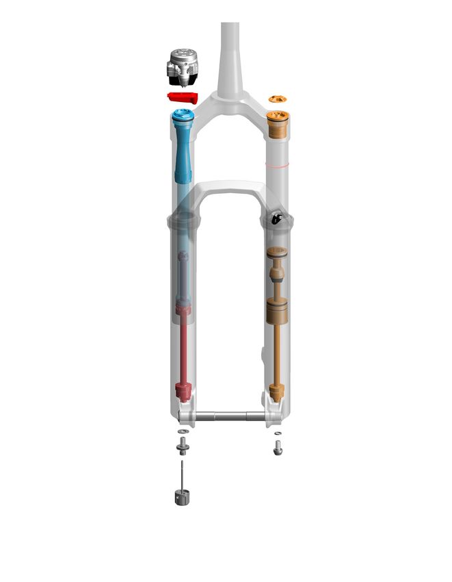
SRAM LLC WARRANTY
THIS WARRANTY GIVES YOU SPECIFIC LEGAL RIGHTS AGAINST SRAM, LLC. YOU MAY ALSO HAVE OTHER RIGHTS THAT VARY FROM
STATE TO STATE, COUNTRY, OR PROVINCE. THIS WARRANTY DOES NOT AFFECT YOUR STATUTORY RIGHTS. TO THE EXTENT THIS
WARRANTY IS INCONSISTENT WITH THE LOCAL LAW, THIS WARRANTY SHALL BE DEEMED MODIFIED TO BE CONSISTENT WITH SUCH
LAW. FOR A FULL UNDERSTANDING OF YOUR RIGHTS, CONSULT THE LAWS OF YOUR COUNTRY, PROVINCE, OR STATE.
EXTENT OF LIMITED WARRANTY
Except as otherwise set forth herein, SRAM warrants its bicycle components to be free from defects in materials or workmanship for a period of two
(2) years after original purchase of the product.
SRAM warrants all Zipp MOTO Wheels and Rims to be free from defects in materials or workmanship for the lifetime of the product.
SRAM warrants all non-electronic Zipp branded bicycle components, Model Year 2021 or newer, to be free from defects in materials or workmanship
for the lifetime of the product.
GENERAL PROVISIONS
This warranty only applies to the original owner and is not transferable. Claims under this warranty must be made through the retailer where the
bicycle or the SRAM product was purchased or a SRAM authorized service location. Original proof of purchase is required. All SRAM warranty claims
will be evaluated by a SRAM authorized service location whereupon acceptance of the claim the product will be repaired, replaced, or refunded at
SRAM's discretion. To the extent allowed by local law claims under this warranty must be made during the warranty period and within one (1) year
following the date on which any such claim arises.
NO OTHER WARRANTIES
EXCEPT AS DESCRIBED HEREIN, AND TO THE EXTENT ALLOWED BY LOCAL LAW, SRAM MAKES NO OTHER WARRANTIES, GUARANTIES, OR
REPRESENTATIONS OF ANY TYPE (EXPRESS OR IMPLIED), AND ALL WARRANTIES (INCLUDING ANY IMPLIED WARRANTIES OF REASONABLE
CARE, MERCHANTABILITY, OR FITNESS FOR A PARTICULAR PURPOSE) ARE HEREBY DISCLAIMED.
LIMITATIONS OF LIABILITY
EXCEPT AS DESCRIBED HEREIN, AND TO THE EXTENT PERMITTED BY LAW, IN NO EVENT SHALL SRAM OR ITS THIRD PARTY SUPPLIERS BE
LIABLE FOR DIRECT, INDIRECT, SPECIAL, INCIDENTAL, OR CONSEQUENTIAL DAMAGES. SOME STATES (COUNTRIES AND PROVINCES) DO NOT
ALLOW THE EXCLUSION OR LIMITATION OF INCIDENTAL DAMAGES, SO THE ABOVE LIMITATION MAY NOT APPLY TO YOU.
LIMITATIONS OF WARRANTY
This warranty does not apply to products that have been incorrectly installed, adjusted, and/or maintained according to the respective SRAM user
manual. The SRAM user manuals can be found online at sram.com/service.
This warranty does not apply to damage to the product caused by a crash, impact, abuse of the product, non-compliance with manufacturer's
specifications of intended usage, or any other circumstances in which the product has been subjected to forces or loads beyond its design.
This warranty does not apply when the product has been modified, including but not limited to, any attempt to open or repair any electronic and
electronic related components, including the motor, controller, battery packs, wiring harnesses, switches, and chargers.
This warranty does not apply when the serial number or production code has been deliberately altered, defaced, or removed.
SRAM components are designed for use only on bicycles that are pedal powered or pedal assisted (e-Bike/Pedelec).
Notwithstanding anything else set forth herein, the battery pack and charger warranty does not include damage from power surges, use of improper
charger, improper maintenance, or such other misuse.
This warranty shall not cover damages caused by the use of parts of different manufacturers or parts that are not compatible or suitable for use with
SRAM components.
This warranty shall not cover damages resulting from commercial (rental) use.
WEAR AND TEAR
This warranty does not apply to normal wear and tear. Wear and tear parts are subject to damage as a result of normal use, failure to service
according to SRAM recommendations, and/or riding or installation in conditions or applications other than recommended.
WEAR AND TEAR PARTS INCLUDE:
• Aero bar pads            • Chains                                        • Rear shock mounting                 • Stripped threads/bolts (aluminum,
• Air sealing o-rings      • Corrosion                                       hardware and main seals               titanium, magnesium or steel)
• Batteries                • Disc brake rotors                             • Rubber moving parts                 • Tires
• Bearings                 • Dust seals                                    • Shifter and Brake cables            • Tools
• Bottomout pads           • Free hubs, Driver bodies, Pawls                 (inner and outer)                   • Transmission gears
• Brake pads               • Foam rings, Glide rings                       • Shifter grips                       • Upper tubes (stanchions)
• Bushings                 • Handlebar grips                               • Spokes                              • Wheel braking surfaces
• Cassettes                • Jockey wheels                                 • Sprockets

ZIPP IMPACT REPLACEMENT POLICY
Zipp branded products, Model Year 2021 or newer, are covered under a lifetime impact-damage replacement policy. This policy can be used to obtain
a replacement of a product in the event of non-warranty impact damage occurring while riding your bicycle. See www.zipp.com/support for more
information.
SAFETY FIRST!
We care about YOU. Please, always wear your safety glasses
 and protective gloves when servicing RockShox products.
          Protect yourself! Wear your safety gear!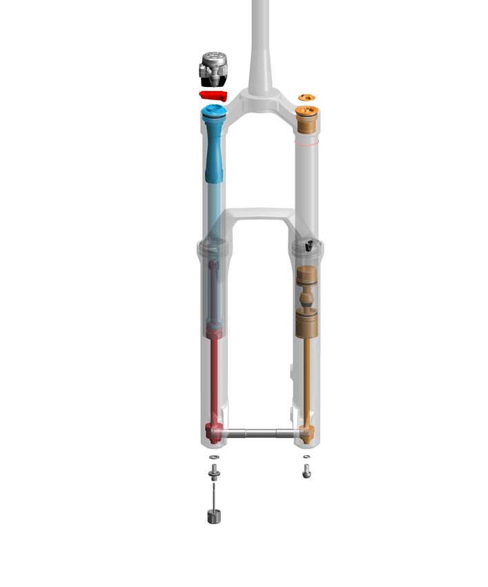
TABLE OF CONTENTS
ROCKSHOX SERVICE...........................................................................................................................................................................................5
       PART PREPARATION .......................................................................................................................................................................................................................................5
       SERVICE PROCEDURES..................................................................................................................................................................................................................................5
       PARTS, TOOLS, AND SUPPLIES...................................................................................................................................................................................................................6
       RECOMMENDED SERVICE INTERVALS..................................................................................................................................................................................................... 7
       RECORD YOUR SETTINGS............................................................................................................................................................................................................................. 7
       TORQUE VALUES.............................................................................................................................................................................................................................................. 7
       OIL VOLUME AND LUBRICANT....................................................................................................................................................................................................................8

EXPLODED VIEW - 2022 ZEB ULTIMATE FLIGHT ATTENDANT...................................................................................................................9

EXPLODED VIEW - 2022 LYRIK ULTIMATE FLIGHT ATTENDANT..............................................................................................................10

EXPLODED VIEW - 2022 PIKE ULTIMATE FLIGHT ATTENDANT.................................................................................................................11

EXPLODED VIEW - FLIGHT ATTENDANT CONTROL MODULE - ZEB, LYRIK, PIKE.................................................................................12

EXPLODED VIEW - LOWER LEG FEATURES - ZEB, LYRIK, PIKE................................................................................................................. 13

EXPLODED VIEW - BUTTERCUP - ZEB, LYRIK, PIKE....................................................................................................................................14

LOWER LEG REMOVAL AND SERVICE............................................................................................................................................................15
                                                                                                         50/200 HOUR SERVICE
       LOWER LEG REMOVAL.................................................................................................................................................................................................................................. 15
                                                                                                              50 HOUR SERVICE
       LOWER LEG SERVICE.................................................................................................................................................................................................................................... 17
                                                                                                            200 HOUR SERVICE
       LOWER LEG SEAL SERVICE......................................................................................................................................................................................................................... 19

AIR SPRING SERVICE - DEBONAIR+.............................................................................................................................................................. 22
                                                                                                            200 HOUR SERVICE
       AIR SPRING REMOVAL................................................................................................................................................................................................................................. 22
       BUTTERCUP REMOVAL - AIR SPRING SHAFT...................................................................................................................................................................................... 25
       DEBONAIR+ - AIR SPRING TRAVEL CHANGE AND BOTTOMLESS TOKENS (OPTIONAL).................................................................................................... 27
       DEBONAIR+ - TRAVEL AND BOTTOMLESS TOKEN TUNING (OPTIONAL)................................................................................................................................. 27
       DEBONAIR+ - BOTTOMLESS TOKENS INSTALLATION (OPTIONAL)............................................................................................................................................ 27
       DEBONAIR+ - AIR SPRING TRAVEL CHANGE AND BOTTOMLESS TOKENS (OPTIONAL).................................................................................................... 28
       AIR SPRING SERVICE.................................................................................................................................................................................................................................... 28
       AIR SPRING ASSEMBLY............................................................................................................................................................................................................................... 30
       BUTTERCUP INSTALLATION - AIR SPRING SHAFT............................................................................................................................................................................ 33
       AIR SPRING INSTALLATION........................................................................................................................................................................................................................ 35

DAMPER SERVICE............................................................................................................................................................................................. 39
                                                                                                            200 HOUR SERVICE
       FLIGHT ATTENDANT CONTROL MODULE REMOVAL....................................................................................................................................................................... 39
       DAMPER REMOVAL....................................................................................................................................................................................................................................... 42
       BUTTERCUP REMOVAL - DAMPER SHAFT........................................................................................................................................................................................... 43
       DAMPER SERVICE.......................................................................................................................................................................................................................................... 45
       DAMPER ASSEMBLY..................................................................................................................................................................................................................................... 48
       DAMPER BLEED..............................................................................................................................................................................................................................................50
       TEST LOCKOUT COMPRESSION.............................................................................................................................................................................................................. 53
       BUTTERCUP INSTALLATION - DAMPER SHAFT.................................................................................................................................................................................. 54
       DAMPER INSTALLATION.............................................................................................................................................................................................................................. 57
       CONTROL MODULE INSTALLATION....................................................................................................................................................................................................... 59
                                                                                                         50/200 HOUR SERVICE
       LOWER LEG INSTALLATION....................................................................................................................................................................................................................... 63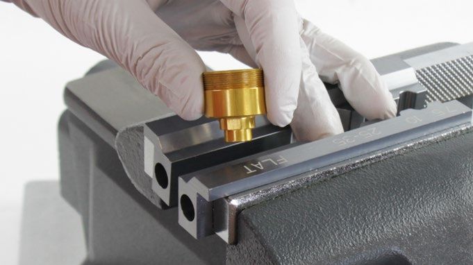
RockShox Service
We recommend that you have your RockShox suspension serviced by a qualified bicycle mechanic. Servicing RockShox suspension requires
knowledge of suspension components, as well as the use of specialized tools and lubricants/fluids. Failure to follow the procedures outlined in this
service manual may cause damage to your component and void the warranty.
Visit www.sram.com/service for the latest RockShox Spare Parts catalog and technical information. For order information, please contact your local
SRAM distributor or dealer.
Information contained in this publication is subject to change at any time without prior notice.
Your product's appearance may differ from the pictures contained in this publication.
      For recycling and environmental compliance information, please visit: www.sram.com/en/company/about/environmental-policy-and-recycling.

 Part Preparation
Remove the component from the bicycle before service.
Disconnect and remove the remote cable or hydraulic hose from the fork or rear shock, if applicable. For additional information about RockShox
remotes, user manuals are available at www.sram.com.
Clean the exterior of the product with mild soap and water to avoid contamination of internal sealing part surfaces.

 Service Procedures
The following procedures should be performed throughout service, unless otherwise specified.

Clean the part with RockShox Suspension Cleaner or isopropyl alcohol and
a clean, lint-free shop towel. For hard to reach places (e.g. upper tube, lower
leg), wrap a clean, lint-free shop towel around a non-metallic dowel to clean
the inside.
Clean the sealing surface on the part and inspect it for scratches.

Replace the o-ring or seal with a new one from the service kit. Use your
fingers or a pick to pierce and remove the old seal or o-ring.
Apply grease to the new seal or o-ring.

                                  NOTICE
 Do not scratch any sealing surfaces when servicing the product. Scratches
 can cause leaks. Consult the spare parts catalog to replace the damaged
 part.

Use aluminum soft jaws when placing a part in a bench vise.
Tighten the part with a torque wrench to the torque value listed in the red bar.
When using a crowfoot socket and torque wrench, install the crowfoot socket
at 90 degrees to the torque wrench.

                                                                                                                         Specified torque value in N·m (in-lb)

                                                                                                                                RockShox Service                 5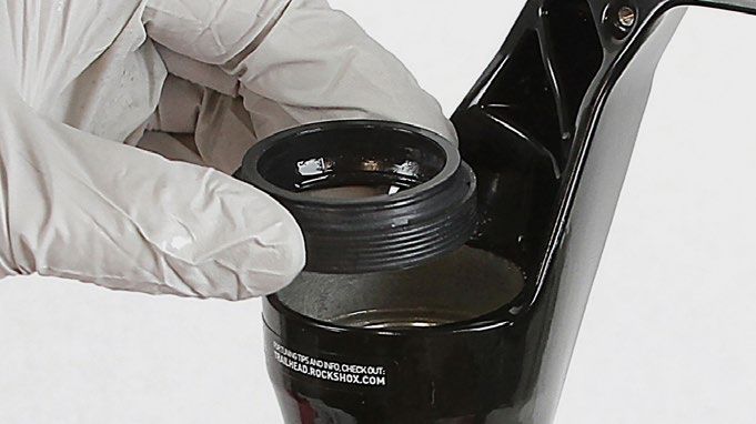
P a r t s , To o l s , a n d S u p p l i e s
Parts                                                                  Bicycle Tools
• 2022 ZEB Ultimate Flight Attendant - 200 Hour Service Kit            • Bicycle work stand
• 2022 Lyrik Ultimate Flight Attendant - 200 Hour Service Kit          • Downhill tire lever
• 2022 Pike Ultimate Flight Attendant - 200 Hour Service Kit           • Shock pump
Safety and Protection Supplies                                         Common Tools
• Apron                                                                • Adjustable wrench or open end wench: 23, 25 mm
• Clean, lint-free shop towels                                         • Bench vise with aluminum soft jaw inserts
• Nitrile gloves                                                       • Crowfoot: 23, 25 mm
• Oil pan                                                              • Flat blade screwdriver
• Safety glasses                                                       • Hex bit sockets: 2, 2.5, 5 mm
Lubricants and Fluids                                                  • Hex wrenches: 2, 2.5, 5, 8 mm
• Maxima PLUSH 3wt Suspension Oil                                      • Internal retaining ring pliers (large) - air spring retaining ring (ZEB)
• Maxima PLUSH Dynamic Suspension Lube                                 • Long plastic or wooden dowel
• SRAM Butter Grease                                                   • Pick (metallic) - air spring retaining ring (Lyrik/Pike)
• RockShox Suspension Cleaner or isopropyl alcohol                     • Pick (non-metallic) - for all o-rings and seals
RockShox Tools                                                         • Plastic mallet
• RockShox Bleed Syringe                                               • Socket: 27 mm
• RockShox Dust Seal Installation Tool (38 mm) or RockShox x Abbey     • Socket wrench
  Bike Tools 38 mm Flangeless Dust Seal Installation Tool              • Soft jaws (flat, aluminum)
• RockShox Dust Seal Installation Tool (35 mm) or RockShox x Abbey     • Torque wrench
  Bike Tools 35 mm Flangeless Dust Seal Installation Tool
                                                                       • TORX bit socket: T10, T25
• RockShox Reverb Vise Blocks (10 mm slot) or
  RockShox Rear Shock Vise Blocks (10 mm slot)                         • TORX wrench: T10, T25

• RockShox Shock Pump
• RockShox Top Cap/Cassette tool (3/8" / 24 mm) or RockShox x
  Abbey Bike Tools Top Cap/Cassette Tool

                                                       SAFETY INSTRUCTIONS
Always wear safety glasses and nitrile gloves when working with suspension oil.
Place an oil pan on the floor underneath the area where you will be working on the shock or suspension fork.

                                                                                                                        Parts, Tools, and Supplies   6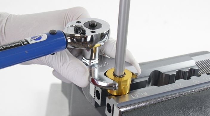
Recommended Service Intervals
Regular service is required to keep your RockShox product working at peak performance. Follow this maintenance schedule and install the service
parts included in each service kit that corresponds with the Service Hours Interval recommendation below. For spare part kit contents and details,
refer to the RockShox Spare Parts Catalog at www.sram.com/service.

  Service Hours Interval         Maintenance                                    Benefit

                                                                                Extends wiper seal lifespan

  Every ride                     Clean dirt from upper tubes and wiper seals    Minimizes damage to upper tubes

                                                                                Minimizes lower leg contamination

                                                                                Restores small bump sensitivity

  Every 50 hours                 Perform lower leg service                      Reduces friction

                                                                                Extends bushing lifespan

                                                                                Extends suspension lifespan

  Every 200 hours                Perform damper and spring service              Restores small bump sensitivity

                                                                                Restores damping performance

 R e c o r d Yo u r S e t t i n g s
Use the table below to record your suspension settings to return your suspension to its pre-service settings. Record your service dates to track
service intervals.

                                                                                                                       Rebound setting - Count the
                                                                                                                       number of clicks while turning
  Service Hours Interval          Date of Service                                Air Pressure
                                                                                                                       the rebound adjuster fully
                                                                                                                       counter-clockwise.

  50

  100

  150

  200

 To r q u e Va l u e s
 Part                                                                           Tool                                  Torque
 Bleed screw - rebound damper seal head                                         TORX T10                              1.7 N•m (15 in-lb)
 Bottom bolt - air spring and damper                                            5 mm hex bit socket                   6.8 N•m (60 in-lb)
 Bottomless Tokens                                                              8 mm hex                              4 N•m (35 in-lb)
 ButterCup housing shaft end plate - end plate to shaft - air and damper        TORX T25                              3.3 N•m (29 in-lb)
 Seal head - rebound damper to damper cartridge tube                            23 mm crowfoot                        5 N•m (45 in-lb)
 Set screw (x2) - Flight Attendant Control Module to compression damper
                                                                                2 mm hex bit socket                   0.25 - 0.5 N•m (2.2 - 4.3 in-lb)
 top cap
 Set screw - rebound adjuster knob                                              2.5 mm hex bit socket                 0.84 N•m (7.5 in-lb)

 Top cap - air spring                                                           RockShox Top Cap/Cassette Tool
                                                                                (or standard cassette tool)           28 N•m (250 in-lb)
 Top cap - compression damper
                                                                                27 mm socket (optional)
 Upper ButterCup housing to lower ButterCup housing - air and damper            25 mm crow foot                       3.3 N•m (29 in-lb)

                                                                                                                  Recommended Service Intervals          7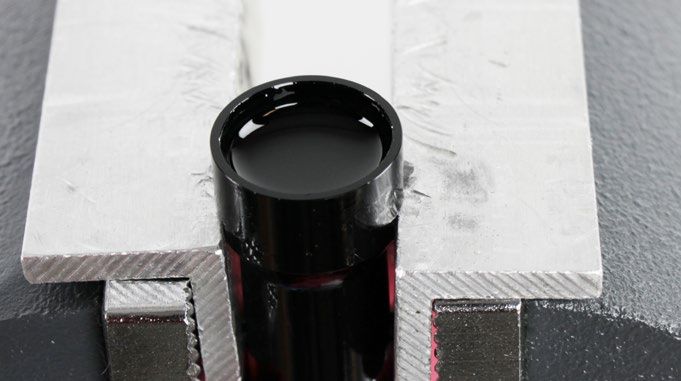
Oil Volume and Lubricant

                                Damper                                                  Spring

                                             Upper Tube          Lower Leg                          Upper Tube              Lower Leg

Model
        Fork        Model       Damper       Oil                 Oil                    Spring      Oil
Year                                                   Volume                 Volume                              Volume    Oil Weight   Volume
                                             Weight              Weight                             Weight
                                                       (mL)                   (mL)                                (mL)      (wt)         (mL)
                                             (wt)                (wt)                               (wt)

        ZEB
                                                                                                    SRAM          Grease
                                                                                                    Butter        Air
                                                                                                    Grease*       Piston
                                                                 Maxima                                                     Maxima
                    Ultimate    Charger      Maxima              PLUSH                                                      PLUSH
2022    Lyrik       Flight      Flight       PLUSH     Bleed     Dynamic      30        DebonAir+                           Dynamic      15
                    Attendant   Attendant    3wt                 Suspension                                                 Suspension
                                                                 Lube                                                       Lube
                                                                                                    Maxima
                                                                                                    PLUSH
                                                                                                    Dynamic       3
                                                                                                    Suspension
        Pike                                                                                        Lube*

*Air Spring Oil / Grease - ZEB, Lyrik, and Pike Ultimate Flight Attendant forks are compatible with Maxima PLUSH Dynamic Suspension Lube and
SRAM Butter Grease.

                                                                                                                 Oil Volume and Lubricant      8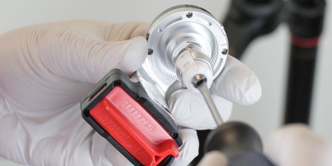
Exploded View - 2022 ZEB Ultimate Flight Attendant

                                                                                                                     Air Spring Assembly
        Steerer tube

                                                                                                                     Compression Damper
       Flight Attendant                                                                                              Assembly
        Control Module
                                                                                  Air cap
                                                                                                                     Rebound Damper
                                                                                   Air spring top cap                Assembly
                  Battery

              Battery block
                                                                                     Bottomless Token(s) 35 mm grey (optional)

 Compression damper top cap                                                            Sag o-ring

                          Crown

                                                                                            Upper tube
             Compression damper

                                                                                                 Lower leg arch

                              Damper tube

                                                                                                    Brake hose guide

                                Dust wiper seal

                                      Foam ring                                                          Air spring piston
                          Rebound damper piston
                                                                                                          Top out cup
                                                                                                           Top out bumper
                                                                                                            Air spring seal head

                                                                                                              Air seal head spacer

                                                                                                               Retaining ring

                              Rebound damper seal head
                                             Bleed port

                                                                                                                    Air spring shaft

                                                                                                                             ButterCup (air shaft)

                                            ButterCup (damper shaft)
                                                                                                                                 Crush washer
                                                        Maxle Stealth

                                                                                                                                   Air spring
                                                                                                                                   bottom bolt
                                                          Crush washer

                                                     Rebound bottom bolt

                                                        Rebound adjuster knob

                                                                                Exploded View - 2022 ZEB Ultimate Flight Attendant                   9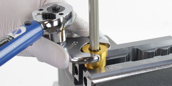
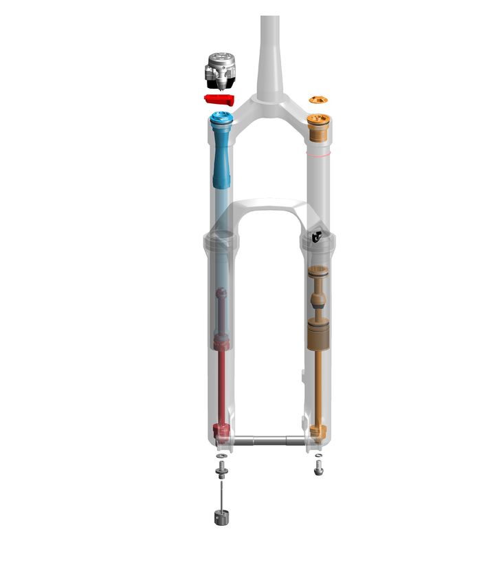
Exploded View - 2022 Lyrik Ultimate Flight Attendant

                                                                                                                     Air Spring Assembly
        Steerer tube

                                                                                                                     Compression Damper
       Flight Attendant                                                                                              Assembly
        Control Module
                                                                               Air cap
                                                                                                                     Rebound Damper
                                                                                                                     Assembly
                  Battery                                                        Air spring top cap

              Battery block
                                                                                   Bottomless Token(s) 35 mm grey (optional)
 Compression damper top cap
                                                                                     Sag o-ring
                          Crown

                                                                                         Upper tube

              Compression damper

                                                                                            Lower leg arch

                            Damper tube
                                                                                                  Brake hose guide

                              Dust wiper seal

                                    Foam ring                                                          Air spring piston

                                                                                                        Top out cup
                                                                                                         Top out bumper

                            Rebound damper piston                                                         Air spring seal head

                                                                                                            Air seal head spacer

                                                                                                              Retaining ring

                              Rebound damper seal head
                                             Bleed port

                                                                                                                  Air spring shaft

                                                                                                                           ButterCup (air shaft)

                                          ButterCup (damper shaft)                                                            Crush washer

                                                      Maxle Stealth                                                             Air spring
                                                                                                                                bottom bolt
                                                        Crush washer

                                                  Rebound bottom bolt

                                                     Rebound adjuster knob

                                                                             Exploded View - 2022 Lyrik Ultimate Flight Attendant                  10
Exploded View - 2022 Pike Ultimate Flight Attendant
Air Spring Assembly
Steerer tube
Flight Attendant Compression Damper
Control Module Assembly
Air cap
Rebound Damper
Assembly
Battery Air spring top cap
Battery block
Bottomless Token(s) 35 mm grey (optional)
Compression damper top cap
Crown
Sag o-ring
Upper tube
Compression damper
Lower leg arch
Brake hose guide
Dust wiper seal
Air spring piston
Foam ring
Top out cup
Top out bumper
Rebound damper piston
Air spring seal head
Air seal head spacer
Retaining ring
Rebound damper seal head
Bleed port
Air spring shaft
ButterCup (air shaft)
ButterCup (damper shaft)
Crush washer
Maxle Stealth
Air spring bottom bolt
Crush washer
Rebound bottom bolt
Rebound adjuster knob
Exploded View - 2022 Pike Ultimate Flight Attendant 11Exploded View - Flight Attendant Control Module - ZEB, Lyrik, Pike
Mode / Setting LED
(−) Adjust button
Menu button (+) Adjust button
Flight Attendant Control Module
Set screw
AXS LED indicator
AXS button Output driver (compression damper adjuster)
SRAM battery
Compression damper
Battery latch
Battery block
SRAM battery
Exploded View - Flight Attendant Control Module - ZEB, Lyrik, Pike 12Exploded View - Lower Leg Features - ZEB, Lyrik, Pike
Fender mount (x3)
Pressure Relief Valve (x2)
Bolt (x2)
Dropout Adapter (x2)
Exploded View - Lower Leg Features - ZEB, Lyrik, Pike 13Exploded View - ButterCup - ZEB, Lyrik, Pike
Damper shaft Air spring shaft
Upper ButterCup housing Upper ButterCup housing
Bushing Bushing
Upper bumper O-ring
ButterCup shaft end plate ButterCup shaft end plate
Lower ButterCup housing Lower ButterCup housing
Lower bumper Bumper
O-ring
Lower housing alignment bolt
Exploded View - ButterCup - ZEB, Lyrik, Pike 14Lower Leg Removal and Service
50/200 Hour Service Lower Leg Removal
ZEB is pictured in this section. Procedures are the same for Lyrik and Pike unless otherwise described.
1 Remove the air valve cap.
2 Depress the Schrader valve and release all air pressure.
⚠ CAUTION - EYE HAZARD
Verify all pressure is removed from the fork before proceeding.
Failure to do so can result in injury and/or damage to the fork. Wear
safety glasses.
3 Turn the rebound adjuster knob counter-clockwise until it stops. This is
the full open/fast rebound setting.
Counter-clockwise Rebound - Full Open Setting
4 Loosen the set screw and remove the rebound damper adjuster knob.
2.5 mm
Lower Leg Removal and Service 155 Place an oil pan beneath the fork to catch the draining oil.
Loosen both bottom bolts 3 to 4 turns.
Spring side 5 mm Damper side 5 mm
6 Strike each bolt head to dislodge the spring and damper shaft
ButterCups from the lower leg. The bolt head should contact the
bottom of the lower leg.
Remove each bottom bolt. Clean each bolt and set them aside.
Pike 27.5" and 29", Lyrik 29": Insert a 5 mm hex wrench into the bolt,
and tap the wrench to avoid damage to the lower leg.
NOTICE
Do not strike the fork lower leg with mallet as this could damage the
lower leg.
Mallet Spring side Spring side
Mallet Damper side Damper side
7 Firmly pull the lower leg downward until fluid begins to drain. Continue
pulling downward to remove the lower leg.
If the lower leg does not slide off of the upper tube or if oil does not
drain from either side, the press fit of the shaft(s) into the lower leg may
still be engaged. Reinstall the bottom bolts 2 to 3 turns and repeat the
previous step.
NOTICE
Do not strike the fork arch with any tool when removing the lower
leg as this could damage the lower leg.
50 Hour Service Continue the 50 Hour Service with Lower Leg Service.
200 Hour Service Continue the 200 Hour Service with Lower Leg Seal Service.
Lower Leg Removal 1650 Hour Service Lower Leg Service
1 Remove the foam rings.
Pick
2 Clean the foam rings.
Replace the foam rings if worn, damaged, or excessively contaminated.
RockShox Suspension Cleaner
3 Soak the foam rings in Maxima PLUSH Dynamic Suspension Lube.
Lube.
Maxima PLUSH Dynamic Suspension Lube
Lower Leg Service 174 Clean the inside and outside of the lower leg.
Clean the wiper seals.
RockShox Suspension Cleaner Dowel
5 Install the foam rings under the wiper seals.
Confirm the foam rings are installed evenly and square in the space
under the wiper seals and do not protrude out of the groove.
50 Hour Service Continue the 50 Hour Service with Lower Leg Installation.
Lower Leg Service 18200 Hour Service Lower Leg Seal Service
1 Remove and discard the foam rings.
Remove the outer wire springs from the dust wiper seals.
Pick
2 Stabilize the lower leg on a bench top. Place the tip of a downhill
tire lever under the wiper seal. Press down on the downhill tire lever
handle to remove the seal.
Repeat on the other side. Discard the wiper seals.
NOTICE
Keep the lower leg stable. Do not allow the lower leg to twist in
opposite directions, compress toward each other, or be pulled apart.
This will damage the lower leg.
Downhill tire lever
3 Clean the inside and outside of the lower leg.
RockShox Suspension Cleaner Dowel
Lower Leg Seal Service 194 Soak new foam rings in Maxima PLUSH Dynamic Suspension Lube.
Install the new foam rings into the lower leg.
Maxima PLUSH Dynamic Suspension
Lube
5 Remove the outer wire spring from each new dust wiper seal and set
them aside.
6 Insert the narrow end of a new wiper seal into the recessed end of the
RockShox Dust Seal Installation Tool.
38 mm - ZEB
35 mm - Lyrik and Pike
RockShox Dust Seal Installation Tool
7 Stabilize the lower leg on a bench top. Hold the lower leg steady and
press, or tap with a mallet, the wiper seal into the lower leg until the top
of the seal is flush with the top of the lower leg.
Repeat on the other side.
NOTICE
Only press, or tap with a mallet, the wiper seal into the lower leg
until it is flush with the top surface of the lower leg. Pressing the
wiper seal below the top surface of the lower leg will compress the
foam ring.
RockShox Dust Seal Installation Tool Mallet
Lower Leg Seal Service 208 Install the outer wire springs.
Lower Leg Seal Service 21Air Spring Service - DebonAir+
A ZEB air spring assembly is pictured in this section. Procedures are the same for ZEB, Lyrik, and Pike unless otherwise described.
200 Hour Service Air Spring Removal
⚠ WARNING - EYE HAZARD
Verify all pressure is removed from the fork before proceeding. Depress the Schrader valve again to remove any remaining air pressure. Failure to
do so can result in injury and/or damage to the fork.
NOTICE
Inspect each part for scratches. Do not scratch any sealing surfaces when
servicing your suspension. Scratches can cause leaks.
When replacing seals and o-rings, use your fingers or a pick to remove the
seal or o-ring. Spray RockShox Suspension Cleaner or isopropyl alcohol
onto each part and clean with a clean lint-free shop towel.
Apply SRAM Butter Grease to the new seals and o-rings.
SRAM Butter Grease
1 Remove the air spring top cap. Press down firmly when loosening the
top cap.
NOTICE
The fork top caps are tightened to a high torque value. Ensure
the fork is held securely in the bicycle stand. To avoid damage
to the top cap, press the top cap tool squarely and firmly down
when loosening. Use a socket wrench with a long handle for extra
leverage.
Clean the upper tube threads.
Top cap / Cassette tool
2 Remove the top cap o-ring and discard it.
Apply grease to a new o-ring and install it.
Air Spring Service - DebonAir+ 223 Remove the retaining ring.
Use your finger to guide the retaining ring and protect the air spring
shaft during removal.
NOTICE
Do not scratch the air spring shaft. Scratches on the air shaft will
allow air to bypass the seal head into the lower leg, resulting in
reduced spring performance.
Retaining ring pliers ZEB
Lyrik/Pike: Wrap a shop towel tightly around the air shaft to protect it.
Metal Pick Lyrik / Pike
Air Spring Removal 234 Push the shaft half way into the upper tube, then quickly and firmly pull
the shaft out to dislodge the seal head.
Remove the air spring assembly and seal head spacer from the upper
tube.
NOTICE
Do not scratch the inside of the upper tube. Scratches will allow air
to bypass the seals resulting in reduced spring performance.
ZEB Pike (pictured) and Lyrik
5 Clean the inside and outside of the upper tube.
Inspect the inside and outside of the upper tube for damage.
NOTICE
Scratches on the inside surface of the upper tube can cause air to
leak. If an internal scratch is visible, the crown steerer upper tube
assembly may need to be replaced.
RockShox Suspension Cleaner
Dowel Dowel
RockShox Suspension Cleaner
Air Spring Removal 24200 Hour Service ButterCup Removal - Air Spring Shaft
1 Clamp the lower ButterCup housing into a vise with Reverb Vise Blocks
or RockShox Rear Shock Vise Blocks on the wrench flats, with the air
spring oriented upward.
Hold the air spring shaft for support and unthread the upper ButterCup
housing (25 mm) from the lower ButterCup housing.
25 mm or adjustable open end wrench
2 Remove the air spring assembly from the lower ButterCup housing and
set it aside.
3 Remove the ButterCup bumper from the lower ButterCup housing and
discard it.
Pick (non-metallic)
4 Remove the lower ButterCup housing from the vise. Clean the lower
ButterCup housing.
ButterCup Removal - Air Spring Shaft 255 Clamp the air shaft into the 10 mm slot of the RockShox Reverb Vise
Blocks or RockShox Rear Shock Vise Blocks with the air piston oriented
downward.
Clamp the air spring shaft only tight enough so it does not spin when
the ButterCup shaft end plate is removed.
NOTICE
Scratches on the air spring shaft can cause air to leak. If a scratch is
visible the air spring assembly may need to be replaced.
Unthread and remove the ButterCup shaft end plate from the air spring
shaft.
T25 RockShox Vise Blocks 10 mm
6 Remove the ButterCup shaft end plate o-ring (large) and discard it.
The small o-ring does not need to be removed or replaced.
7 Remove the air spring shaft from the vise and vise blocks.
Remove the upper ButterCup housing and bushing assembly from the
air spring shaft and set it aside.
ButterCup Removal - Air Spring Shaft 26D e b o n A i r + - A i r S p r i n g Tr a v e l C h a n g e a n d B o t t o m l e s s To k e n s ( o p t i o n a l )
To increase or decrease the travel of your RockShox fork, the air spring must be replaced with the appropriate length air spring shaft assembly. For
example, to change a fork with a maximum of 140 mm of travel to a maximum of 160 mm of travel, a 160 mm air spring assembly must be installed.
Bottomless Tokens can be added to, or removed from the DebonAir+ (DA) top cap to fine-tune the bottom-out feel and spring curve. Use the table
below to help determine the number of Bottomless Tokens that can be used with each maximum fork travel option. If fork travel is changed from
stock, it may be necessary to add or remove Bottomless Tokens.
Refer to the RockShox Suspension Tuning and Setup Guide for more details.Refer to the RockShox Spare Parts Catalog at www.sram.com/service for
available air spring and Bottomless Token kits.
For part ordering information, please contact your local SRAM distributor or dealer.
D e b o n A i r + - Tr a v e l a n d B o t t o m l e s s To k e n Tu n i n g ( o p t i o n a l )
ZEB - 27.5" Boost & 29" Boost
Fork Travel Bottomless Tokens (grey) Bottomless Tokens (grey)
(mm) Factory Installed Maximum
190 0 4
180 0 4
170 1 4
160 1 5
150 2 5
Lyrik - 27.5" Boost & 29" Boost
Fork Travel Bottomless Tokens (grey) Bottomless Tokens (grey)
(mm) Factory Installed Maximum
160 0 5
150 0 5
140 1 5
Pike - 27.5" Boost & 29" Boost
Fork Travel Bottomless Tokens (grey) Bottomless Tokens (grey)
(mm) Factory Installed Maximum
140 0 4
130 0 5
120 1 5
D e b o n A i r + - B o t t o m l e s s To k e n s I n s t a l l a t i o n ( o p t i o n a l )
Bottomless Tokens reduce air volume in your fork and create greater ramp at the end of the fork travel. Add or remove Tokens to tune your fork's
bottomless feel.
Thread a Bottomless Token into another Bottomless Token, or into the
the bottom of the top cap, and tighten.
8 mm 4 N∙m (35 in-lb) Top cap / Cassette tool
DebonAir+ - Air Spring Travel Change and Bottomless Tokens (optional) 27D e b o n A i r + - A i r S p r i n g Tr a v e l C h a n g e a n d B o t t o m l e s s To k e n s ( o p t i o n a l )
It is optional to change maximum fork travel by replacing the stock air spring shaft assembly with a shorter or longer air spring shaft assembly. If
maximum travel is increased or reduced, use the new complete air spring shaft assembly in the following installation steps. It may also be necessary
to add or remove Bottomless Tokens. Refer to Air Spring Travel Change and Bottomless Tokens for details.
Refer to the RockShox Spare Parts Catalog at www.sram.com/service for available air spring and Bottomless Token kits.
For part ordering information, please contact your local SRAM distributor or dealer.
200 Hour Service Air Spring Service
A ZEB air spring assembly is pictured in this section. Procedures are
the same for ZEB, Lyrik, and Pike air spring assemblies.
Lyrik Pike
1 Remove the air seal head assembly and top out bumper from the air
spring shaft.
Discard the seal head assembly.
NOTICE
Scratches on the air spring shaft can cause air to leak. If a scratch is
visible the air spring assembly may need to be replaced.
2 Remove the top out bumper.
Clean the top out bumper.
Clean and inspect the air spring shaft for damage.
Pick (non-metallic)
DebonAir+ - Air Spring Travel Change and Bottomless Tokens (optional) 283 Remove the glide ring (upper), quad ring, and backup ring (lower) from
the air piston and discard them.
NOTICE
Do not scratch the air piston. Scratches will cause air to leak.
Pick
4 Clean the air piston.
Air Spring Service 29Air Spring Assembly
1 Install a new backup ring (thin, lower) onto the air piston.
Apply grease to the new quad ring seal and install it onto the air piston
above the backup ring.
Install a new glide ring (thick, upper) tapered end upward, above the
quad ring seal.
Set the air spring assembly aside on a clean shop towel.
2 Apply a liberal amount of grease to the air spring shaft.
SRAM Butter Grease
3 Apply a thin layer of grease to the new top out bumper and Install it
onto the air spring shaft.
SRAM Butter Grease
Air Spring Assembly 304 Apply grease to the inner and outer seals on the new seal head.
SRAM Butter Grease SRAM Butter Grease
SRAM Butter Grease
5 Install the new seal head assembly onto the air shaft, flat side first.
Air Spring Assembly 316 Remove the grease from the inner shaft threads.
Air Spring Assembly 32200 Hour Service ButterCup Installation - Air Spring Shaft
1 Install the ButterCup upper housing and bushing assembly onto the air
spring shaft.
2 Apply grease to a new o-ring and install it onto the ButterCup shaft end
plate, over the threads.
Clean all grease from the threads.
SRAM Butter Grease
3 Apply Loctite Threadlocker 2760 (red), or equivalent, to the first two to
three full threads of the ButterCup shaft end plate.
Threadlocker Loctite 2760 - Red
4 Position the upper ButterCup housing above the vise blocks.
Clamp the air shaft into the 10 mm slot of the RockShox Reverb Vise
Blocks or RockShox Rear Shock Vise Blocks.
Clamp the air shaft only tight enough so it does not spin when the
ButterCup is tightened.
NOTICE
Scratches on the air spring shaft can cause air to leak. If a scratch is
visible the air spring assembly may need to be replaced.
Thread the ButterCup shaft end plate into the air shaft and tighten it.
T25 RockShox Vise Blocks 10 mm T25 3.3 N∙m (29 in-lb)
ButterCup Installation - Air Spring Shaft 335 Apply Loctite Threadlocker Blue 242, or equivalent, to three full outer
threads on the lower ButterCup housing.
Theadlocker Loctite 242 - Blue
6 Install a new ButterCup bumper into the lower ButterCup housing, wide
end first.
7 Position the lower ButterCup housing and bumper onto the ButterCup
end plate.
Slide the upper ButterCup housing and bushing assembly up and
thread it onto the lower ButterCup housing finger tight.
8 Remove the air shaft from the vise and vise blocks.
Clamp the lower ButterCup housing into a vise with RockShox Vise
Blocks on the wrench flats, air spring piston oriented upward.
Tighten the upper ButterCup housing onto the lower housing.
25 mm 8.5 N∙m (75 in-lb)
ButterCup Installation - Air Spring Shaft 34200 Hour Service Air Spring Installation
1 Apply a liberal amount of SRAM Butter grease evenly around the end
of a clean plastic dowel, approximately 150 mm from one end. Use
the dowel to apply the grease to the inside surface of the upper tube,
approximately 150 mm into the tube.
Dowel and grease 150 mm
2 Apply grease to the air piston and seal head outer o-rings.
SRAM Butter Grease
3 With the crown steerer upper tube assembly clamped in the bicycle
work stand, orient the upper tubes upward and the steerer tube
oriented downward.
Insert the air spring assembly into the upper tube. Firmly push the air
piston into the upper tube.
Inject 1 mL of Maxima PLUSH Dynamic Suspension Lube into the upper
tube, on top of the air piston and into the negative air chamber.
1 mL PLUSH Dynamic Suspension Lube
Air Spring Installation 354 Insert the air seal head into the upper tube and firmly press it into the
upper tube until it stops.
5 Apply grease to a new seal head spacer o-ring and install it onto the
seal head spacer.
Insert the seal head spacer into the upper tube, o-ring end first, and
seat it into the upper tube step until it stops.
Air Spring Installation 366 ZEB: Eyelet retaining
retaining rings have a sharper edged side and a rounder
edged side. Installing retaining rings with the sharper edged side
facing the tool will allow for easier installation and removal.
Guide the retaining ring with your finger to prevent scratching the air
shaft.
Place the tips of the retaining ring pliers into the eyelets of the
retaining ring, then use the pliers to push the seal head into the upper
tube while installing the retaining ring into the groove.
Confirm the retaining ring is properly seated in the retaining ring
groove by using the retaining ring pliers to rotate the retaining ring
and seal head back and forth a few times.
NOTICE Retaining ring pliers
Do not scratch the air spring shaft. Scratches on the air shaft will
allow air to bypass the seal head into the lower leg, resulting in
reduced spring performance.
Lyrik and Pike: Lift both prong ends from the center of the ring to open
the retaining ring for installation.
Use your fingers to protect and guide the ring over the air shaft.
Insert the inner retaining ring prong end into the upper tube retaining
ring gland.
Using your thumb, guide and push the retaining ring edge, starting
at the installed prong end, around the upper tube edge and into the
gland.
The retaining ring is installed completely when the outer prong end
snaps into the gland.
Confirm the retaining ring is properly seated completely in the
retaining ring gland.
NOTICE
Do not scratch the air spring shaft. Scratches on the air shaft will
allow air to bypass the seal head into the lower leg, resulting in
reduced spring performance.
Air Spring Installation 377 Inject or pour Maxima PLUSH Dynamic Suspension Lube into the air
spring upper tube.
Maxima PLUSH Dynamic Suspension Lube RockShox Bleed Syringe 3 mL
8 Install the air spring top cap into the upper tube and tighten it. Press
down firmly when tightening the top cap.
Top cap/ 28 N∙m (250 in-lb)
Cassette tool
Air Spring Installation 38Damper Service
200 Hour Service Flight Attendant Control Module Removal
1 The compression damper must be in the OPEN position before
removing the Control Module.
Press and hold the Menu button until one LED pulses red.
If necessary, press and release the (+
(+) or (−
(−) adjuster button until the
red OPEN LED pulses.
2 Remove the SRAM battery and install the battery block.
Install the battery cover on the SRAM battery and set it aside.
Optional:: Insert the SRAM battery onto the battery charger.
Optional
3 Loosen each Flight Attendant Control Module set screw.
Do not remove the set screws.
2 mm 2 mm
Damper Service 394 Carefully remove the Flight Attendant Control Module from the
compression damper top cap. Use both thumbs to evenly push the
Control Module straight up and out of the top cap.
NOTICE
Do not damage the internal mechanism when removing the Control
Module.
5 Clean the underside of the Control Module with a damp clean shop
towel.
Set the Control Module aside.
NOTICE
Do not spray any cleaners onto the Control Module.
Flight Attendant Control Module Removal 406 Carefully remove the inner damper top cap / Control Module o-ring
seal.
NOTICE
Do not scratch the o-ring gland. Scratches can cause debris to enter
the top cap under the Flight Attendant Control Module.
Pick
Clean the inside of the top cap and o-ring gland with a damp clean
shop towel.
NOTICE
Do not spray any cleaners into the top cap or on top of the
compression damper.
Flight Attendant Control Module Removal 41200 Hour Service Damper Removal
1 Unthread the damper top cap and remove the damper assembly.
NOTICE
The fork top caps are tightened to a high torque value. Ensure
the fork is held securely in the bicycle stand. To avoid damage
to the top cap, press the top cap tool squarely and firmly down
when loosening. Use a socket wrench with a long handle for extra
leverage.
Clean the upper tube threads.
Top cap / Cassette tool
2 Clean the inside and outside of the upper tube.
RockShox Suspension Cleaner
Dowel Dowel
Damper Removal 42200 Hour Service ButterCup Removal - Damper Shaft
1 Clamp the lower ButterCup housing into a vise with Reverb Vise Blocks
or RockShox Rear Shock Vise Blocks on the wrench flats, with the
damper oriented downward.
Hold the damper shaft for support and unthread the upper ButterCup
housing from the lower housing.
25 mm or adjustable open end wrench
2 Remove the damper assembly from the lower cup and set it aside.
3 Remove the lower ButterCup bumper from the lower ButterCup
housing and discard it.
Remove the lower ButterCup housing from the vise.
Do not remove the alignment bolt.
Pick (non-metallic)
4 Remove the lower ButterCup housing from the vise. Clean the lower
ButterCup housing.
ButterCup Removal - Damper Shaft 435 Clamp the damper shaft into the 10 mm slot of the RockShox Reverb
Vise Blocks or RockShox Rear Shock Vise Blocks with the damper
oriented downward.
Clamp the damper shaft only tight enough so it does not spin when the
ButterCup shaft end plate is removed.
NOTICE
Scratches on the damper shaft can cause oil to leak. If a scratch is
visible the rebound damper assembly may need to be replaced.
Unthread and remove the ButterCup shaft end plate from the damper
shaft.
T25 RockShox Vise Blocks 10 mm
6 Remove the upper ButterCup bumper and discard it.
Remove the upper ButterCup housing and bushing assembly from the
damper shaft.
ButterCup Removal - Damper Shaft 44200 Hour Service Damper Service
1 Clamp the cartridge tube wrench flats in a vise with flat soft jaw inserts,
rebound damper oriented upward.
Wrap a shop towel around the cartridge tube to absorb oil.
Vise and flat soft jaw inserts
2 Unthread and slowly remove the rebound damper and seal head
assembly from the cartridge tube.
23 mm
3 Remove the seal head from the rebound damper shaft and discard it.
4 The solid band glide ring is not removable and only requires cleaning.
Do not remove.
Damper Service 455 Apply grease to the new rebound damper seal head seals.
SRAM Butter Grease
6 Install the new seal head onto the rebound damper shaft, threaded end
first, and slide it towards the piston until it stops.
7 Remove the bleed screw from the seal head.
TORX T10
8 Remove the cartridge tube from the vise and pour the oil into an oil
pan.
Squeeze the bladder to drain the oil from the compression damper
assembly into an oil pan.
Damper Service 469 Clamp the cartridge tube, on the bladder coupler wrench flats, back
into the vise.
Spray RockShox Suspension Cleaner or isopropyl alcohol into the
cartridge tube.
Squeeze the bladder 5-6 times to circulate the cleaner into the damper.
10 Remove the tube from the vise. Orient the tube downward and
squeeze the bladder until the cleaner and any remaining oil is drained
into an oil pan.
Place the tube on a shop towel for a new minutes to allow any excess
cleaner to drain.
11 Dry the cartridge tube and compression damper assembly with
compressed air.
Air compressor and air gun nozzle
Damper Service 47200 Hour Service Damper Assembly
1 Clamp the cartridge tube wrench flats lightly into the vise and soft jaw
inserts. Wrap a shop towel around the tube to absorb any oil.
Pour Maxima PLUSH 3wt suspension oil into the cartridge tube until it
is full.
Squeeze the bladder until trapped bubbles stop purging. Pour
additional oil into the cartridge tube until it is full.
Maxima PLUSH 3wt Suspension Oil
2 The rebound damper must be in the full open/fastest rebound setting
before installation.
Insert the rebound adjuster knob, or 2.5 mm hex wrench, into the
rebound damper shaft until it contacts the rebound adjuster screw.
Turn the knob counter-clockwise until it stops.
Remove the adjuster knob from the shaft.
Damper Assembly 483 Insert the rebound damper piston slowly into the cartridge tube and
thread the sealhead into the tube.
Tigthen the seal head.
23 mm 5.1 N∙m (45 in-lb)
4 Thread the rebound bottom bolt into the shaft 3-4 turns.
Damper Assembly 49200 Hour Service Damper Bleed
1 Draw Maxima PLUSH 3wt suspension oil into a RockShox Bleed
Syringe until it is half full.
Maxima PLUSH 3wt Suspension Oil RockShox Bleed Syringe
2 Thread the syringe bleed fitting into the seal head bleed port.
Depress the plunger to pressurize the damper assembly.
3 Push the rebound damper shaft into the cartridge tube while applying
opposing pressure on the syringe plunger as the syringe fills with oil.
Pull the rebound damper shaft slowly out of the cartridge tube while
applying opposing pressure on the syringe plunger as oil fills the
damper.
Repeat this process until bubbles are no longer pulled from the damper
into the syringe.
Damper Bleed 504 Fully extend the rebound damper shaft. Push the syringe plunger
down, then release the plunger. Allow the bladder to expand and
retract until it stops in a resting position.
5 Unthread the syringe bleed fitting from the bleed port.
⚠ CAUTION
Oil may eject from the bleed port if the bladder is not in a resting
position. Wear safety glasses.
6 Install the bleed screw and tighten it.
Wipe away any excess oil.
T10 1.7 N∙m (15 in-lb)
Damper Bleed 517 Cycle the rebound shaft a few times.
Remove the bottom bolt and clean the damper assembly.
Damper Bleed 52200 Hour Service Te s t L o c k o u t C o m p r e s s i o n
1 Use a Schrader valve core tool to rotate the keyed adjuster clockwise
until it lightly contacts the stop point, to the locked out or firmest
position.
NOTICE
Do not over-rotate the keyed adjuster against the stop point. Over-
rotation, or tightening, against the stop point can damage internal
parts.
Schrader valve core tool
2 Position the rebound damper shaft squarely on a flat surface while
holding the compression circuit closed with the Schrader valve core
tool.
Push down on the damper assembly to test the bleed.
Consistent resistance should be felt with no gaps in movement. If gaps
are felt during compression, repeat the bleed process.
If the bleed was successful, rotate the compression damper keyed
adjuster counter clockwise to the open position, then rotate it one half
turn clockwise.
Schrader valve core tool Schrader valve core tool
Test Lockout Compression 53200 Hour Service ButterCup Installation - Damper Shaft
1 Install the upper ButterCup housing and bushing assembly onto the
damper shaft. Slide the assembly toward the rebound seal head until it
stops.
2 Install a new upper ButterCup bumper, wide end first, onto the damper
shaft.
SRAM Butter Grease
3 Apply Threadlocker Loctite 2760 (red), or equivalent, to the first three
full threads on the end of the end plate.
Threadlocker Loctite 2760 - Red
4 Clamp the damper shaft into the 10 mm slot of the Reverb Vise Blocks
or RockShox Rear Shock Vise Blocks.
Clamp the damper shaft only tight enough so it does not spin when the
ButterCup housing is tightened.
NOTICE
Scratches on the damper shaft can cause oil to leak. If a scratch is
visible the rebound damper assembly may need to be replaced.
Thread the ButterCup shaft end plate into the damper shaft and tighten
it.
T25 RockShox Vise Blocks 10 mm T25 3.3 N∙m (29 in-lb)
ButterCup Installation - Damper Shaft 545 Install the lower ButterCup housing bumper into the lower ButterCup
housing, wide side down, in alignment with the bolt.
6 Apply Threadlocker Loctite 242 (blue), or equivalent, to three full outer
threads on the lower ButterCup housing.
Theadlocker Loctite 242 - Blue
7 Position the upper ButterCup housing and bumper above the vise
blocks.
Install the lower ButterCup housing/bumper assembly onto the
ButterCup shaft end plate; insert the bolt through the end plate bolt
hole.
Slide lower cup to the upper bumper end plate, and position the
alignment bolt through the hole on the end plate.
Thread the upper ButterCup housing onto the lower ButterCup housing
finger tight.
ButterCup Installation - Damper Shaft 558 Remove the damper shaft from the vise and vise blocks.
Clamp the lower ButterCup housing into a vise with RockShox Vise
Blocks on the wrench flats, damper oriented upward.
Tighten the upper ButterCup housing onto the lower housing.
25 mm 8.5 N∙m (75 in-lb)
ButterCup Installation - Damper Shaft 56200 Hour Service Damper Installation
1 Remove the o-ring from the top cap.
Clean the top cap threads and o-ring groove.
Apply grease to a new o-ring and install it.
SRAM Butter Grease
2 Apply grease to a new inner top cap o-ring and install it.
SRAM Butter Grease
Damper Installation 573 Install the damper assembly into the damper side upper tube. Use
your fingers to guide the damper and damper shaft into the upper tube
without scratching the shaft.
Thread the top cap into the upper tube and tighten it. Press down
firmly when tightening the top cap.
Top cap / Cassette tool 28 N∙m (250 in-lb)
Damper Installation 58200 Hour Service Control Module Installation
1 The keyed ends of the Control Module output driver and the
compression damper adjuster must be aligned in the same orientation
before installation.
NOTICE
Confirm the inside of the top cap is clean before installing the
Flight Attendant Control Module. Contamination will affect the
compression damper seal and function of the Control Module.
Check key alignment before installation. If the keys are not aligned,
rotate the adjuster key on the Control Module output driver to the
same orientation as the adjuster key in the compression damper.
Flat blade screwdriver
Control Module Installation 592 Position the back of the Control Module parallel with the crown, and
install the Control Module into the compression damper.
With the keyed ends of the Control Module output driver and
compression damper adjuster aligned, press the Control Module firmly
into the damper and onto the top cap squarely.
If the keyed ends are not aligned the Control Module will not snap
into place inside the compression damper. If this occurs, remove the
Control Module, align the keyed ends, and reinstall the Control Module.
Parallel
NOTICE
For proper clearance and function, the Flight Attendant Control
Module must be installed with the battery oriented to the BACK of
the crown only, and parallel with the fork crown. Installation of the Control Module parallel with crown
Control Module with the battery oriented to the side or front of the
crown will cause permanent damage.
3 Check and confirm the Control Module does not contact any part of
the fork crown. Remove the Control Module, realign, and reinstall if
needed.
Control Module Installation 604 Tighten each set screw evenly finger tight to center the Control Module
position on the top cap.
Tighten each set screw to the specified torque.
NOTICE
To avoid permanent damage to the compression damper top cap, do
not over tighten the set screws.
2 mm 2 mm
2 mm 0.25 - 0.5 N•m (2.2 - 4.3 in-lb) 2 mm 0.25 - 0.5 N•m (2.2 - 4.3 in-lb)
5 Remove the battery block from the Control Module.
Install the battery onto the Control Module.
Control Module and Damper Homing: When the battery is installed,
the Control Module motor will activate and automatically reset and
adjust the compression damper to the full open position. If the Control
Module is properly installed, the action should operate smoothly and
quickly.
If a clicking noise, or repeating motor actions are heard and felt,
the Control Module is installed incorrectly. The output driver and
compression damper keys may not be aligned correctly.
Adjust Alignment:
1. Remove the battery.
2. Partially and evenly loosen each set screw. Do not remove the set
screws or the Control Module.
3. Reinstall the battery.
4. The Control Module and damper adjuster keys should self align and
reset the damper compression position.
5. Tighten each set screw to the specified torque.
If alignment adjustment was unsuccessful, remove the Control Module,
align the output driver and compression keys, and reinstall the Control
Module onto the compression damper top cap. Repeat Control Module
Installation steps 1 - 5.
Control Module Installation 61You can also read