2018-2020 Deluxe - SERVICE MANUAL - SRAM
←
→
Page content transcription
If your browser does not render page correctly, please read the page content below
2018-2020 Deluxe

SERVICE MANUAL

                   GEN.0000000006011 Rev B © 2019 SRAM, LLC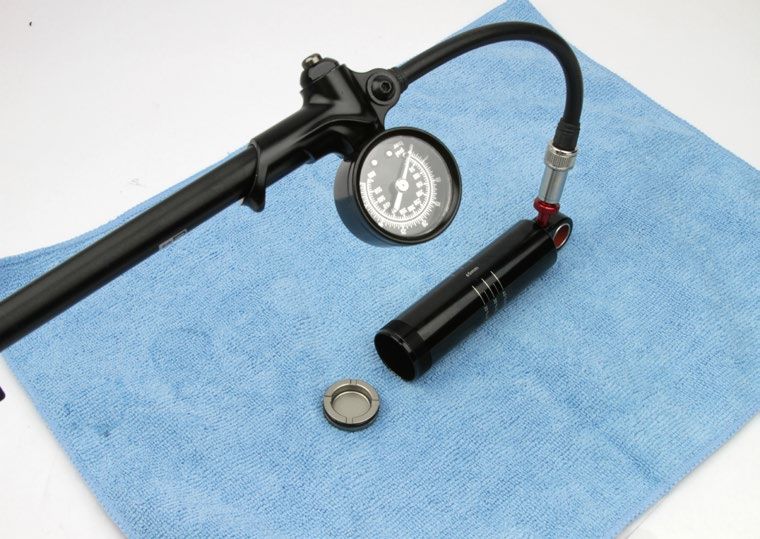
SRAM LLC WARRANTY
EXTENT OF LIMITED WARRANTY
Except as otherwise set forth herein, SRAM warrants its products to be free from defects in materials or workmanship for a period of two years after
original purchase. This warranty only applies to the original owner and is not transferable. Claims under this warranty must be made through the
retailer where the bicycle or the SRAM component was purchased. Original proof of purchase is required. Except as described herein, SRAM
makes no other warranties, guaranties, or representations of any type (express or implied), and all warranties (including any implied
warranties of reasonable care, merchantibility, or fitness for a particular purpose) are hereby disclaimed.

LOCAL LAW
This warranty statement gives the customer specific legal rights. The customer may also have other rights which vary from state to state (USA),
from province to province (Canada), and from country to country elsewhere in the world.
To the extent that this warranty statement is inconsistent with the local law, this warranty shall be deemed modified to be consistent with such law,
under such local law, certain disclaimers and limitations of this warranty statement may apply to the customer. For example, some states in the
United States of America, as well as some governments outside of the United States (including provinces in Canada) may:
  a. Preclude the disclaimers and limitations of this warranty statement from limiting the statutory rights of the consumer
     (e.g. United Kingdom).
  b. Otherwise restrict the ability of a manufacturer to enforce such disclaimers or limitations.
For Australian customers:
This SRAM limited warranty is provided in Australia by SRAM LLC, 1000 W. Fulton Market, 4th Floor, Chicago, IL, 60607, USA. To make a warranty
claim please contact the retailer from whom you purchased this SRAM product. Alternatively, you may make a claim by contacting SRAM Australia,
6 Marco Court, Rowville 3178, Australia. For valid claims SRAM will, at its option, either repair or replace your SRAM product. Any expenses
incurred in making the warranty claim are your responsibility. The benefits given by this warranty are additional to other rights and remedies that
you may have under laws relating to our products. Our goods come with guarantees that cannot be excluded under the Australian Consumer Law.
You are entitled to a replacement or refund for a major failure and for compensation for any other reasonably foreseeable loss or damage. You are
also entitled to have the goods repaired or replaced if the goods fail to be of acceptable quality and the failure does not amount to a major failure.

LIMITATIONS OF LIABILITY
To the extent allowed by local law, except for the obligations specifically set forth in this warranty statement, in no event shall SRAM or its third party
suppliers be liable for direct, indirect, special, incidental, or consequential damages.

LIMITATIONS OF WARRANTY
This warranty does not apply to products that have been incorrectly installed and/or adjusted according to the respective SRAM user manual. The
SRAM user manuals can be found online at sram.com, rockshox.com, avidbike.com, truvativ.com, or zipp.com.
This warranty does not apply to damage to the product caused by a crash, impact, abuse of the product, non-compliance with manufacturers
specifications of usage or any other circumstances in which the product has been subjected to forces or loads beyond its design.
This warranty does not apply when the product has been modified, including, but not limited to any attempt to open or repair any electronic and
electronic related components, including the motor, controller, battery packs, wiring harnesses, switches, and chargers.
This warranty does not apply when the serial number or production code has been deliberately altered, defaced or removed.
This warranty does not apply to normal wear and tear. Wear and tear parts are subject to damage as a result of normal use, failure to service
according to SRAM recommendations and/or riding or installation in conditions or applications other than recommended.
Wear and tear parts are identified as:
• Dust seals                           • Stripped threads/bolts                • Handlebar grips                       • Transmission gears
• Bushings                               (aluminium, titanium, magnesium       • Shifter grips                         • Spokes
• Air sealing o-rings                    or steel)                             • Jockey wheels                         • Free hubs
• Glide rings                          • Brake sleeves                         • Disc brake rotors                     • Aero bar pads
• Rubber moving parts                  • Brake pads                            • Wheel braking surfaces                • Corrosion
• Foam rings                           • Chains                                • Bottomout pads                        • Tools
• Rear shock mounting hardware         • Sprockets                             • Bearings                              • Motors
  and main seals                       • Cassettes                             • Bearing races                         • Batteries
• Upper tubes (stanchions)             • Shifter and brake cables (inner       • Pawls
                                         and outer)

Notwithstanding anything else set forth herein, the battery pack and charger warranty does not include damage from power surges, use of
improper charger, improper maintenance, or such other misuse.
This warranty shall not cover damages caused by the use of parts of different manufacturers.
This warranty shall not cover damages caused by the use of parts that are not compatible, suitable and/or authorised by SRAM for use with SRAM
components.
This warranty shall not cover damages resulting from commercial (rental) use.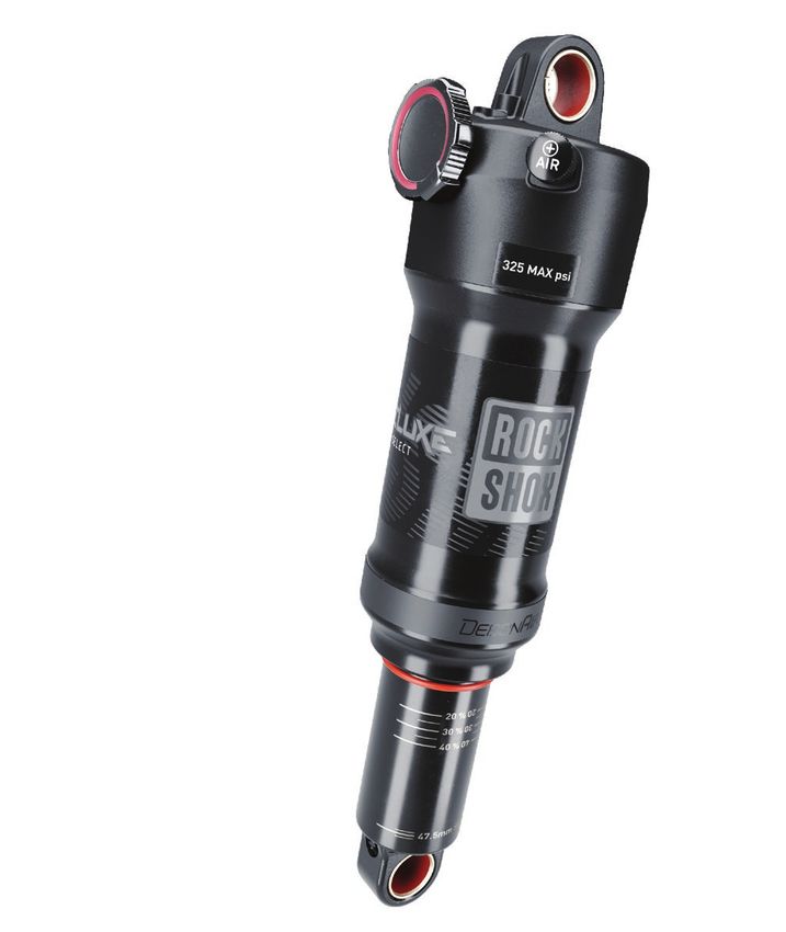
SAFETY FIRST!
We care about YOU. Please, always wear your safety glasses and
     protective gloves when servicing RockShox products.
            Protect yourself! Wear your safety gear!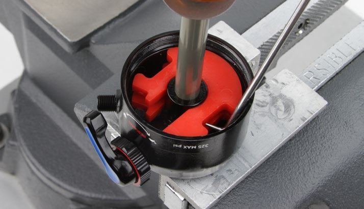
TABLE OF CONTENTS
GETTING STARTED...............................................................................................................................................................................................6
       RECOMMENDED SERVICE INTERVALS.....................................................................................................................................................................................................6
       RECORD YOUR SETTINGS.............................................................................................................................................................................................................................6
       TORQUE VALUES..............................................................................................................................................................................................................................................6
       COMPREHENSIVE PARTS, TOOLS, AND SUPPLIES LIST.................................................................................................................................................................... 7

EXPLODED VIEW - DELUXE ULTIMATE RCT / NUDE......................................................................................................................................8

EXPLODED VIEW - DELUXE RT3/RT/RL/R/DELUXE SELECT+/SELECT.......................................................................................................9

EXPLODED VIEW - DELUXE RLR / ULTIMATE REMOTE...............................................................................................................................10

EXPLODED VIEW - DELUXE BEARING MOUNT............................................................................................................................................10

REMOTE CABLE AND HOUSING REMOVAL - RLR AND ULTIMATE REMOTE ONLY................................................................................11
       PARTS, TOOLS, AND SUPPLIES.................................................................................................................................................................................................................. 11
       REMOTE CABLE AND HOUSING REMOVAL........................................................................................................................................................................................... 11

SHOCK EYELET SERVICE..................................................................................................................................................................................12
       MOUNTING HARDWARE AND BUSHING SERVICE............................................................................................................................................................................. 12
       PARTS, TOOLS, AND SUPPLIES................................................................................................................................................................................................................. 12
       MOUNTING HARDWARE REMOVAL......................................................................................................................................................................................................... 12
       EYELET BUSHING REMOVAL...................................................................................................................................................................................................................... 15
       BEARING MOUNT SERVICE......................................................................................................................................................................................................................... 16
       PARTS, TOOLS, AND SUPPLIES................................................................................................................................................................................................................. 16
       BEARING REMOVAL....................................................................................................................................................................................................................................... 16
       BEARING INSTALLATION............................................................................................................................................................................................................................. 18
       DAMPER BEARING REPLACEMENT......................................................................................................................................................................................................... 20

DELUXE SERVICE...............................................................................................................................................................................................21
       PARTS, TOOLS AND SUPPLIES.................................................................................................................................................................................................................. 21
                                                                                                         50/200 HOUR SERVICE
       AIR CAN REMOVAL....................................................................................................................................................................................................................................... 22
       BOTTOMLESS TUNING................................................................................................................................................................................................................................ 25
       AIR CAN SERVICE.......................................................................................................................................................................................................................................... 27
                                                                                                            200 HOUR SERVICE
       DAMPER BODY SERVICE.............................................................................................................................................................................................................................. 31
       PISTON SERVICE............................................................................................................................................................................................................................................ 33
       IFP AND DAMPER BODY SERVICE............................................................................................................................................................................................................ 41
       SHOCK ASSEMBLY AND BLEED .............................................................................................................................................................................................................. 43
       REMOTE SPRING SERVICE - RLR/ULTIMATE REMOTE...................................................................................................................................................................... 46
                                                                                                         50/200 HOUR SERVICE
       AIR CAN INSTALLATION.............................................................................................................................................................................................................................. 49

SHOCK EYELET ASSEMBLY.............................................................................................................................................................................. 51
       EYELET BUSHING INSTALLATION............................................................................................................................................................................................................ 51
       MOUNTING HARDWARE INSTALLATION............................................................................................................................................................................................... 52

REMOTE CABLE AND HOUSING INSTALLATION - RLR/ULTIMATE REMOTE.......................................................................................... 54
       PARTS, TOOLS, AND SUPPLIES................................................................................................................................................................................................................ 54
       REMOTE CABLE AND HOUSING INSTALLATION................................................................................................................................................................................ 54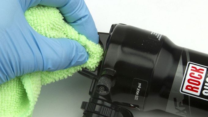
RockShox Service
We recommend that you have your RockShox suspension serviced by a qualified bicycle mechanic. Servicing RockShox suspension requires
knowledge of suspension components, as well as the use of specialized tools and lubricants/fluids. Failure to follow the procedures outlined in this
service manual may cause damage to your component and void the warranty.
Visit www.sram.com/service for the latest RockShox Spare Parts catalog and technical information. For order information, please contact your local
SRAM distributor or dealer.
Information contained in this publication is subject to change at any time without prior notice.
Your product's appearance may differ from the pictures contained in this publication.
      For recycling and environmental compliance information, please visit www.sram.com/company/environment.

 Part Preparation
Remove the component from the bicycle before service.
Disconnect and remove the remote cable or hydraulic hose from the fork or rear shock, if applicable. Instructions to remove the remote cable and
housing can be found in the Remote Cable and Housing Removal section. For additional information about RockShox remotes, user manuals are
available at www.sram.com/service.
Clean the exterior of the product with mild soap and water to avoid contamination of internal sealing part surfaces.

 Service Procedures
The following procedures should be performed throughout service, unless otherwise specified.

Clean the part with RockShox Suspension Cleaner or isopropyl alcohol and a
clean, lint-free shop towel.
Clean the sealing surface on the part and inspect it for scratches.

Replace the o-ring or seal with a new one from the service kit. Use your
fingers or a pick to pierce and remove the old seal or o-ring.
Apply RockShox Dynamic Seal Grease to the new seal or o-ring. If a brush is
used to apply grease, confirm there are no loose bristles in the grease or on
the part.

                                     NOTICE
 Do not scratch any sealing surfaces when servicing the product. Scratches
 can cause leaks. Consult the spare parts catalog to replace the damaged
 part.

To prevent damage to the shock, use aluminum soft jaws and position the                                                Specified torque value in N·m (in-lb)
eyelet in the vise so that the adjustment knobs are clear of the
vise jaws. For bearing mount shocks, wrap a shop towel around the eyelet,
then clamp the eyelet flat into the vise.
Tighten the part with a torque wrench to the torque value listed in the red bar.
When using a crowfoot socket and torque wrench, install the crowfoot socket
at 90 degrees to the torque wrench.

                                                                                                                                  RockShox Service             5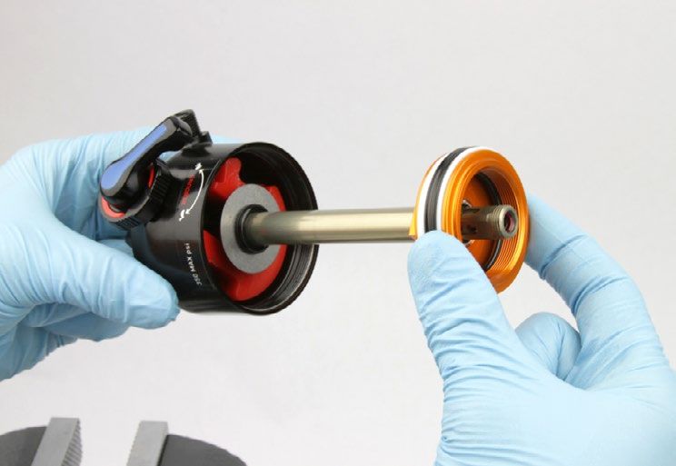
Getting Started

 Recommended Service Intervals
Regular service is required to keep your RockShox product working at peak performance. Follow this maintenance schedule and install the service
parts included in each service kit that corresponds with the Service Hours Interval recommendation below. For spare part kit contents and details,
refer to the RockShox Spare Parts Catalog at www.sram.com/service.

 Service Hours Interval            Maintenance                                        Benefit
                                                                                      Extends wiper seal lifespan
              Every ride           Clean dirt from shock damper body                  Minimizes damage to shock damper body
                                                                                      Minimizes air can contamination
                                                                                      Reduces friction
         Every 50 Hours            Perform air can service
                                                                                      Restores small bump sensitivity
                                                                                      Extends suspension lifespan
        Every 200 Hours            Perform damper and spring service
                                                                                      Restores damping performance

 R e c o r d Yo u r S e t t i n g s
Use the charts below to record your shock settings to return your shock to its pre-service settings. Record your service date to track
service intervals.

                                                                                                                Rebound setting - count the number
   Service Hours
                                   Date of Service                              Air Pressure                    of clicks while turning the rebound
      Interval
                                                                                                                adjuster fully counter-clockwise.
         50
         100
         150
         200

 To r q u e Va l u e s

 Part                                 Tool                                                 Torque
 Air can (shaft eyelet)               13 mm crowfoot                                       4.5 N•m (40 in-lb)
 Piston nut                           RCT / RT3, 2019-2020 RL / RT: 12 mm socket           RCT / NUDE: 6.2 N•m (55 in-lb)
                                      2018 RLR / RL / RT; 2018-2020 R: 10 mm socket        2018-2020 RT3 / RLR/ RL / RT / R: 4.5 N•m (40 in-lb)
                                      NUDE: NUDE Piston Bolt Socket
 Lock Piston (RCT / NUDE)             RCT / NUDE Lock Piston Tool                          4.5 N•m (40 in-lb)
 Seal head/air piston                 17 mm crowfoot                                       28 N•m (248 in-lb)
 Ferrule lock screw (RLR only)        2 mm hex                                             0.9 N•m (7 in-lb)
 Cable set screw (RLR only)           2 mm hex                                             0.8 N•m (7 in-lb)
 Cable spool cap (RLR only)           T25 TORX                                             0.75 N•m (6-7 in-lb)

                                                                                                                                  Getting Started     6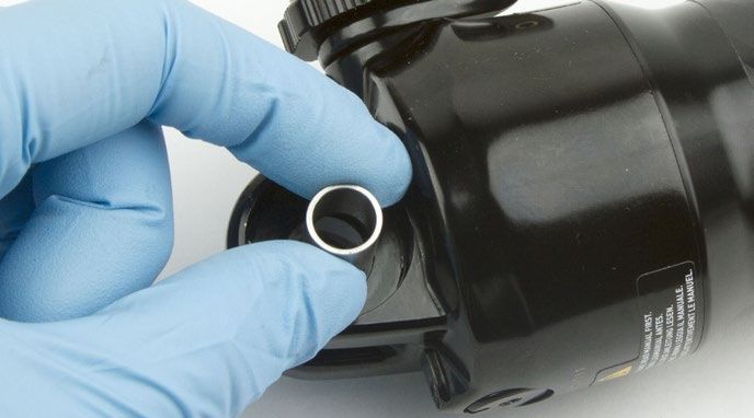
C o m p r e h e n s i v e P a r t s , To o l s , a n d S u p p l i e s L i s t
Parts                                                       RockShox Tools
• Deluxe Service Kit - 50 hours                             • RockShox 1/2" x 1/2" rear shock bushing removal/installation tool
• Deluxe Service Kit - 200 hours                            • RockShox Air Valve Adapter Tool - Rear Shock
• Deluxe Remote Service Kit - 200 hours                     • RockShox Deluxe IFP Height Tool
• Deluxe Remote Spring Service Kit                          • RockShox NUDE Piston Bolt Socket
• Rear Shock Bearing Kit - Deluxe/Super Deluxe              • RockShox RCT / NUDE Lock Piston Tool
• Eyelet Bearing Deluxe/Super Deluxe (Damper body only)     • RockShox Rear Shock Vise Block
• Shift cable and housing                                   • RockShox Rear Shock Body Vise Block
Safety and Protection Supplies                              Common Tools
• Apron                                                     • Adjustable wrench
•   Clean, lint-free shop towels                            • Bearing press tool: 22 mm (OD) x 10 mm (ID)
•   Nitrile gloves                                          • Bench vise with aluminium soft jaws
•   Oil pan                                                 • Cable and housing cutters
•   Safety glasses                                          • Crowfoot socket wrenches: 13 mm, 17 mm
Lubricants and Fluids                                       • Hammer
• Isopropyl alcohol                                         • Hex wrenches: 1.5 mm, 2 mm, 3 mm
• RockShox Dynamic Seal Grease                              • Hex bit sockets: 1.5 mm, 2 mm, 3 mm
• Maxima Extra 15w50 Suspension Oil                         • Metric caliper or small metric ruler
• Maxima PLUSH 7wt Suspension Oil                           • Needle nose pliers
• Loctite Threadlocker Blue 242                             • Open end wrenches: 13 mm, 17 mm
                                                            • Pick
Bicycle Tools
                                                            • Socket wrenches: 10 mm (RLR/R, 2018 RL/RT) and
• Schrader valve core tool
                                                              12 mm (RCT/RT3, 2019 RL/RT)
• High Pressure Shock Pump 600 psi
                                                            • Small diameter punch
                                                            • Strap wrench
                                                            • Torque wrench
                                                            • TORX wrench: T25

                                                                               Comprehensive Parts, Tools, and Supplies List      7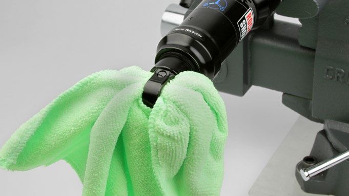
Exploded View - Deluxe Ultimate RCT / NUDE

Ultimate RCT (2020)                                                                  NUDE (2020)

                                               Shaft eyelet

                                                                                                                              Rebound adjuster
                                               Air valve
                                               Rebound adjuster                                                               Compression knob
                                               Compression knob

                                               Threshold lever

                                                                                                                              NUDE sealhead token

                                               Bottom out washer and o-ring
                                               Bleed screw and
                                               compression ball

                                               Seal head / air piston

                                                                                          Air Can
                                               Main piston

                                               Spacer shims and
                                               lock shims

                                               Lock piston

                                               Top hat assembly

                                                                                         Air can

   Counter Measure

IFP (Internal Floating Piston)

                                                                                                        Quad seal

NUDE (2020)                                                      Damper body                         Backup ring

                                                                                                        Wiper seal
                     Main piston

                                                                                            Sag indicator o-ring

                        Spacer shims and
                        lock shims

                          Lock piston                                   Damper air/nitrogen fill port

                                                                        Damper body eyelet
                            Top hat assembly

                                                                                                   Exploded View - Deluxe Ultimate RCT / NUDE    8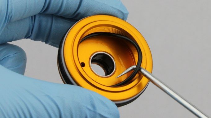
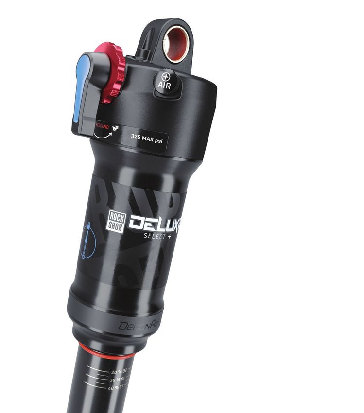
Exploded View - Deluxe RT3/RT/RL/R/Deluxe Select+/Select

Select + (2020)
RT3 (2018-2020)                                                                                   Select (2020)
RL/ RT (2018-2018)                                                                                R (2018-2020)
                                                        Shaft eyelet

                                                        Air valve
                                                        Rebound adjuster
                                                                                                                                       Rebound adjuster

                                                        Compression lever

                                                        Bottom out washer and o-ring

                                                        Bleed screw and
                                                        compression ball

                                                        Seal head / air piston

                                                                                                    Air Can

                                                        Main piston

                                                        Top hat assembly
                                                        (RLR/ 2018 RL/RT)

          Counter Measure
                                                                                                  Air can

IFP (Internal Floating Piston)

                                                                                                                  Quad seal

RL/RT (2019)                                                            Damper body                              Backup ring

                                                                                                                  Wiper seal
                     Main piston

                                                                                                      Sag indicator o-ring

                        Top hat assembly

                                                                                 Damper air/nitrogen fill port

                           IFP
                                                                                 Damper body eyelet
                           (Internal Floating Piston)

                                                                                          Exploded View - Deluxe RT3/RT/RL/R/Deluxe Select+/Select    9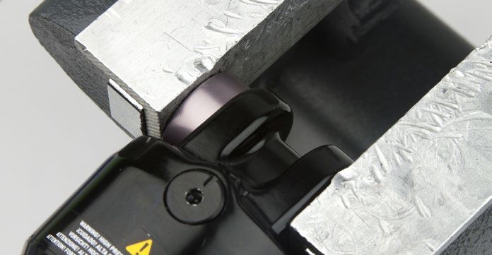
Exploded View - Deluxe RLR / Ultimate Remote

Ultimate Remote (2020)
RLR (2018-2019)                                                                     Remote Spring

                                               Shaft eyelet
                                               Cable set screw                                                    Preloader lock screw
                                               Air valve
                                                                                                                         Spring bushing
                                               Rebound adjuster

                                                   Cable spool cap                                                               Remote spring
                                                                                                                                         Spring
                                                                                                                                         tang
                                               Cable hanger
                                               Ferrule lock screw
                                               Ferrule

                                                                                                                                     Spring
                                                                                                                                     preloader

Exploded View - Deluxe Bearing Mount

    Dust Cover                                                                                     Damper body
                 Bearing
                           Shaft eyelet

                                          Spacer    Bearing                                     Bearing

                                                                                                                               Bearing
                                                                                                                                            Dust
                                                                     Dust cover
                                                                                                                                            Cover

                                                                                  Bearing
                                                                                  Housing

                                                                           Cap Screws

                                                                                            Exploded View - Deluxe RLR / Ultimate Remote          10
Remote Cable and Housing Removal - RLR and Ultimate Remote Only
Prior to servicing the rear shock, remove the remote cable and housing from the shock, then remove the shock from the bicycle frame according to
the bicycle manufacturer's instructions. Replace the cable and housing after performing shock service (see the
Remote Cable and Housing Installation - RLR Only section).
P a r t s , To o l s , a n d S u p p l i e s
Safety and Protection Supplies Common Tools
• Nitrile gloves • Cable and housing cutters
• Safety glasses • Hex wrench: 2 mm
• TORX wrench: T25
Remote Cable and Housing Removal
Use a T25 mm hex wrench to remove the cable spool cap.
1
The cable spool will rotate with the spool cap. Continue to rotate the
spool cap counter-clockwise until it begins to loosen.
T25
Use a 2 mm hex wrench to loosen the cable set screw, then use cable
2 and housing cutters to cut the cable.
Cable and housing cutters
Use a 2 mm hex wrench to loosen the ferrule lock screw. Remove the
ferrule, housing, and cable from the cable bracket.
Discard the cable, housing, and ferrule.
2 mm
2 mm
Remote Cable and Housing Removal - RLR and Ultimate Remote Only 11Shock Eyelet Service
Mounting Hardware and Bushing Service
Prior to servicing the rear shock, remove it from the bicycle frame according to the bicycle manufacturer's instructions. Once the shock is removed
from the bicycle, remove the mounting hardware before performing any service.
P a r t s , To o l s , a n d S u p p l i e s
Parts RockShox Tools
• Deluxe Service Kit - 50 hours • RockShox 1/2" x 1/2" rear shock bushing removal/installation tool
• Deluxe Service Kit - 200 hours Lubricants and Fluids
• Deluxe Remote Service Kit - 200 hours • RockShox Dynamic Seal Grease
Safety and Protection Supplies Common Tools
• Apron • Bench vise with aluminium soft jaws
• Clean, lint-free shop towels • Open end wrenches: 13 mm (2)
• Nitrile gloves • Adjustable wrench
• Safety glasses
Mounting Hardware Removal
NOTICE
To prevent damage to the shock, use aluminium soft jaws and position the eyelet in the vise so that the adjustment knobs are clear of the vise jaws.
Some mounting hardware is easily removed using only your fingers.
Try to remove the end spacers with your fingernail or small screwdriver,
then push the bushing pin out of the bushing. If this works, continue to
the next section.
If you are unable to remove the mounting hardware using your fingers,
use the RockShox rear shock bushing removal/installation tool.
Catcher Push pin
Threaded rod
Rear shock bushing removal/installation tool
Thread the small end of the push pin onto the threaded rod until the
1 rod is flush or slightly protrudes from the hex-shaped end of the
push pin.
Shock Eyelet Service 12Insert the threaded rod through the shaft eyelet until the push pin rests
2 against the bushing pin.
Thread the large, open end of the catcher along the rod until it rests on
the end spacer.
Clamp the catcher in a vise or hold it secure with a 13 mm open
3 end or adjustable wrench.
NOTICE
Do not scratch the air can as you turn the wrench.
Use a second 13 mm wrench to thread the push pin along the rod until
it stops against the end spacer.
Unthread the push pin from the threaded rod to remove the end
spacer and the bushing pivot pin.
13 mm 13 mm
If the bushing pin does not remove easily, reinsert the threaded rod
4 and push pin through the eyelet shaft.
Thread the large, open end of the catcher along the rod until it rests
against the shaft eyelet.
Use a 13 mm wrench to thread the push pin along the rod until it stops
against the end spacer.
13 mm 13 mm
Mounting Hardware Removal 13Unthread the catcher from the threaded rod.
5
Remove the end spacer and bushing pin from the tool.
Repeat steps 2-4 for the damper eyelet.
Set the mounting hardware aside until you have finished servicing
the shock.
Mounting Hardware Removal 14Eyelet Bushing Removal
To replace damaged or worn out bushings, use the RockShox rear shock bushing removal/installation tool.
Insert the threaded rod through the shaft eyelet until the base of the
1 push pin rests against the bushing.
Thread the large, open end of the catcher onto the rod until it rests on
the eyelet.
Clamp the catcher in a vise or hold it secure with a 13 mm wrench.
2
Use a second 13 mm wrench to thread the push pin along the rod until
the push pin pushes the eyelet bushing out of the eyelet.
13 mm 13 mm
Unthread the catcher from the threaded rod. Remove the tool from the
3 shaft eyelet and discard the old bushing.
Repeat steps 1-3 for the other eyelet.
Set the bushings aside until you have finished servicing
your shock.
Eyelet Bushing Removal 15Bearing Mount Service
Replace the bearings if they are not spinning freely, or if they are making a creaking noise.
P a r t s , To o l s , a n d S u p p l i e s
Parts Common Tools
• Rear Shock Bearing Kit - Deluxe/Super Deluxe • Bearing press tool: 22 mm (OD) x 10 mm (ID)
• Eyelet Bearing Deluxe/Super Deluxe (Damper body only) • Hammer
Safety and Protection Supplies • Small diameter punch
• Apron • Vise with soft jaws
• Clean, lint-free shop towels
• Nitrile gloves
• Safety glasses
Bearing Removal
Remove the dust cover.
1
To prevent damage to the air valve, remove the bearing on the side
2 opposite of the air valve first. Place a punch against the back of the
opposite bearing, and tap out the bearing.
Hammer Punch
Bearing Mount Service 16Turn the shock over and place the punch against the back of the other
3 bearing, and tap out the bearing.
NOTICE
Do not damage the air valve when tapping out the bearing.
Hammer Punch
Spray isopropyl alcohol in the bearing bores and clean them
4 with a shop towel.
Bearing Removal 17Bearing Installation
Install a new bearing into one bearing bore, then clamp the eyelet and
1 bearing into a vise with soft jaws. Press the bearing into the bearing
22 mm (OD) x 10 mm (ID) bearing press tool
bore until it is flush with the eyelet.
Loosen the vise, and align the bearing press tool with the bearing, then
tighten the vise. Press the bearing into the bearing bore until it stops.
NOTICE
Do not overtighten the bearing. Overtightening can damage the
bearing and cause it to malfunction.
To prevent damage to the bearing, make sure that the bearing press
tool contacts both the inner and outer races of the bearing.
Bearing press tool
Insert a new spacer into the eyelet, then install a new bearing into the
2 other bearing bore. Clamp the eyelet and bearing into a vise with soft
jaws, then press the bearing into the bearing bore until it is flush with
the eyelet.
Loosen the vise, and align the bearing press tool with the bearing, then
tighten the vise. Press the bearing into the bearing bore until it stops.
NOTICE
Do not overtighten the bearing. Overtightening can damage the
bearing and cause it to malfunction.
To prevent damage to the bearing, make sure that the bearing press
tool contacts both the inner and outer races of the bearing.
Bearing press tool
Bearing Installation 18Remove the shock from the vise. The bearings should sit approximately
3 1 mm below the outer edge of the bearing bore. Reinstall dust covers
before installing the shock on the bicycle.
Bearing Installation 19Damper Bearing Replacement
Loosen the cap screws and remove the bearing assembly from the
1 shock.
The dust covers may fall off. This is normal.
3 mm
NOTICE
If you are completing the 50 or 200 hour service, set the bearing assembly aside until service is complete. The air can cannot be removed with the
bearing assembly installed.
Install the new bearing assembly and screws onto the shock. Tighten
2 the cap screws to 6.2 N·m (55 in-lb).
3 mm 6.2 N•m (55 in-lb)
Damper Bearing Replacement 20Deluxe Service
Prior to servicing your rear shock, remove it from the bicycle frame according to the bicycle manufacturer's instructions. Once the shock is removed
from the bicycle, remove the mounting hardware before performing any service (see the Mounting Hardware And Bushing Service section).
P a r t s , To o l s a n d S u p p l i e s
Parts RockShox Tools
• Deluxe Service Kit - 50 hours • RockShox Air Valve Adapter Tool - Rear Shock
• Deluxe Service Kit - 200 hours • RockShox Deluxe IFP Height Tool
• Deluxe Remote Service Kit - 200 hours • RockShox NUDE Piston Bolt Socket
• Deluxe Remote Spring Service Kit • RockShox RCT / NUDE Lock Piston Tool
Safety and Protection Supplies • RockShox Rear Shock Vise Block
• Apron • RockShox Rear Shock Body Vise Block
• Clean, lint-free shop towels Common Tools
• Nitrile gloves • Bench vise with aluminium soft jaws
• Oil pan • Crowfoot socket wrenches: 13 mm, 17 mm
• Safety glasses • Hex wrenches: 1.5 mm, 2 mm, 3 mm
Lubricants and Fluids • Hex bit sockets: 1.5 mm, 2 mm, 3 mm
• Isopropyl alcohol • Metric caliper or small metric ruler
• RockShox Dynamic Seal Grease • Open end wrenches: 13 mm, 17 mm
• Pick
• Maxima Extra 15w50 Suspension Oil
• Socket wrenches: 10 mm (RLR/R, 2018 RL/RT) and 12 mm (RCT/RT3,
• Maxima PLUSH 7wt Suspension Oil
2019 RL/RT)
• Loctite Threadlocker Blue 242
• Strap wrench
Bicycle Tools
• Torque wrench
• Schrader valve core tool
• High Pressure Shock Pump 600 psi • Needle nose pliers
⚠ WARNING
Before disassembly or service of any air system remove the air pressure from all air chambers and remove the air valve cores.
If your shock will not return to full extension, do not attempt to service or disassemble your shock. Attempting to service a shock that will not return
to full extension can cause severe and/or fatal injuries.
SAFETY INSTRUCTIONS
Always wear safety glasses and nitrile gloves when working with suspension fluid.
Place an oil pan on the floor underneath the area where you will be working on the shock.
Deluxe Service 2150/200 Hour Service Air Can Removal
NOTICE
When replacing seals and o-rings, use your fingers or a pick to remove the
seal or o-ring. Spray isopropyl alcohol on each part and clean with a shop
towel. Apply grease to the new seal or o-ring. Only use RockShox Dynamic
Seal Grease when servicing RockShox shocks.
To prevent damage to the shock use aluminium soft jaws and position the
eyelet in the vise so that the adjustment knobs are clear of the
vise jaws. For bearing mount shocks, wrap a shop towel around the eyelet,
then clamp the eyelet flat into the vise.
Inspect each part for scratches. Do not scratch any sealing surfaces when
servicing your suspension. Scratches can cause leaks.
To record your adjustment settings, turn the rebound adjuster knob
1 counter-clockwise until it stops, while counting the number of detent
NUDE
clicks. This will assist you with post-service set up.
RCT/NUDE: Rotate the compression knob to the minus position.
RT3/RL/RT: Turn the compression lever to the unlocked position.
RLR: The compression circuit is unlocked by default once the remote
cable is removed.
NUDE
RTC
RL/RT
RT3
Air Can Removal 22Record your air pressure setting to assist with post-service set up.
2
Remove the air valve cap by hand. Use a small hex wrench to lightly
depress the Schrader valve and slowly release all air pressure from the
air can.
⚠ CAUTION
Do not disassemble a pressurized shock, this can cause suspension
fluid or debris to forcefully eject from the shock. Wear safety glasses.
Slowly release the air from the air can to make sure the air is removed
from both chambers. Quickly releasing the air can trap air in the
negative chamber and cause the air can to forcefully eject from the
shock upon disassembly.
Use a Schrader valve tool to remove and reinstall the valve core from
the valve body to make sure all air has been removed.
Clamp the shaft eyelet into a vise, with the shock positioned
3 horizontally.
Remove the sag indicator.
4
Air Can Removal 23Insert a shop towel through the damper body eyelet to prevent the air
5 can from forcefully ejecting from the shock.
⚠ CAUTION- EYE HAZARD
The air can may still have air pressure in the negative chamber, which
may cause the air can to forcefully eject from the shock upon
disassembly. Wear safety glasses.
Use a strap wrench to remove the air can. Wrap the strap around the
6 section of the air can furthest from the shaft eyelet. Turn the wrench
counter-clockwise to unthread the air can.
Once it is completely unthreaded, slowly pull the air can along the
damper body to remove it and the Counter Measure.
Remove the shop towel from the damper body eyelet.
Vacuum pressure will increase as you pull the air can along the
damper body, and will suddenly release when the air can is pulled
over the air piston.
NOTICE
Do not place the strap wrench on the air can decal.
Counter Measure
Air Can Removal 24B o t t o m l e s s Tu n i n g
Bottomless Tokens and Gnar Dog Tokens reduce air volume in your Gnar Dog Tokens
rear shock and create greater progression at the end of the shock's
travel. Add or remove tokens to tune your shock's bottomless feel.
Gnar Dog Tokens are equivalent to 2.5 Bottomless Tokens.
Bottomless Tokens 3 Tokens Max
Gnar Dog Tokens 1 Gnar Dog Token + 2 Bottomless Tokens Max
NUDE: do not remove tokens.
Bottomless Tokens
Sonar Tokens: Factory installed in certain Specialized shocks. Sonar Tokens
Compatible with standard eyelet shocks only. Not sold separately.
Bottomless Tokens: Clamp the shaft eyelet into the vise. Bottomless Tokens
Move the bottom out washer and o-ring away from the shaft eyelet,
then snap the token onto the damper shaft with the tabbed side facing
the air valve. Slide the token down the damper shaft until it contacts
the other tokens or the eyelet. Slide the bottom out washer and o-ring
onto the tokens.
Install up to three Bottomless Tokens.
Bottomless Tokens
Gnar Dog Token: Clamp the shaft eyelet into the vise. Gnar Dog Tokens
Remove any existing tokens from the eyelet. Move the bottom out
washer and o-ring away from the shaft eyelet, then snap the Gnar Dog
Token onto the damper shaft with the flat side facing out of the eyelet.
Slide the token down the damper shaft until it contacts the eyelet.
Only one Gnar Dog Token may be installed. If one Gnar Dog Token
is installed, a maximum of two additional Bottomless Tokens can be
installed. Slide the bottom out washer and o-ring onto the tokens.
NOTICE
The Gnar Dog Token must be the first token installed into the eyelet.
Any additional Bottomless Tokens must be installed after the Gnar
Dog Token is installed. Gnar Dog Tokens
Bottomless Tuning 25Token Removal: Clamp the shaft eyelet into the vise.
Move the bottom out washer and o-ring away from the shaft eyelet.
Use a pick to separate the token from the other tokens or the shaft
eyelet, then remove the token from the shaft.
NOTICE
Do not scratch the damper shaft, shaft eyelet, or the eyelet o-ring.
Scratches can cause leaks.
Pick
1 Gnar Dog Token + 2 Bottomless Tokens Max 2650/200 Hour Service Air Can Service
NOTICE
When replacing seals and o-rings, use your fingers or a pick to remove the
seal or o-ring. Spray isopropyl alcohol on each part and clean with a shop
towel. Apply grease to the new seal or o-ring. Only use RockShox Dynamic
Seal Grease when servicing RockShox shocks.
Inspect each part for scratches. Do not scratch any sealing surfaces when
servicing your suspension. Scratches can cause leaks.
Use your fingers to remove the o-ring on the outside of the air can.
1
Spray isopropyl alcohol on the air can threads and eyelet body threads
and clean them with a shop towel.
Install a new o-ring.
Use a pick to remove the air can wiper seal located in the top groove.
2
Air Can Service 27Use a pick to remove the backup ring from the second groove inside
3 the air can.
Use a pick to pierce and remove the quad seal from the bottom of the
4 second groove in the air can.
Spray isopropyl alcohol inside the air can and clean it with a shop
5 towel. Remove a glove and use your finger to inspect the inside
and outside of the air can for scratches, dents, or other surface
deformations. Replace the air can if it is scratched or damaged.
Install the quad seal by inserting one end into the deepest groove in
6 the air can, then push the remainder of the ring into the groove.
Air Can Service 28Install the backup ring by inserting one end into the air can, then push
7 the remainder of the ring into the can, so that it rests on top of the
quad seal.
Orient the new wiper seal step side up. Install it into the wiper seal
8 groove at the top of the air can.
Spray isopropyl alcohol on the air can threads and eyelet body threads
9 and clean them with a shop towel.
Apply a small amount of RockShox Dynamic Seal Grease to the quad
seal, backup ring, and wiper seal.
Set the air can aside.
Air Can Service 29Clamp the eyelet vertically in the vise.
10
Use your fingers to remove the seal head/air piston seal and
glide rings.
Spray isopropyl alcohol on the seal head/air piston and clean it
with a shop towel.
Install the thicker glide ring below the seal head/air piston seal, and the
thinner glide ring above.
To continue with the 50 Hour Service go to Air Can Installation.
To continue with the 200 Hour Service go to Damper Body Service.
Air Can Service 30200 Hour Service Damper Body Service
NOTICE
When replacing seals and o-rings, use your fingers or a pick to remove the
seal or o-ring. Spray isopropyl alcohol on each part and clean with a shop
towel. Apply grease to the new seal or o-ring. Only use RockShox Dynamic
Seal Grease when servicing RockShox shocks.
To prevent damage to the shock use aluminium soft jaws and position the
eyelet in the vise so that the adjustment knobs are clear of the
vise jaws. For bearing mount shocks, wrap a shop towel around the eyelet,
then clamp the eyelet flat into the vise.
Inspect each part for scratches. Do not scratch any sealing surfaces when
servicing your suspension. Scratches can cause leaks.
Use a Schrader valve tool to remove the damper air/nitrogen fill port
1 cap. Use a small hex wrench or pick to depress the Schrader valve and
release all air pressure from the damper.
Once the pressure has been released, depress the Schrader valve a
second time. If the Schrader valve is able to move, the shock has been
completely depressurized.
If the Schrader valve does not move at all, the shock is still
pressurized and will need to be sent to an authorized RockShox
dealer for further service.
⚠ CAUTION - EYE HAZARD
Verify all pressure is removed from the shock before proceeding.
Failure to do so can cause the damper body to separate from the
shaft eyelet at a high velocity. Wear safety glasses.
Use a Schrader valve tool to remove and reinstall the Schrader valve
2 core from the damper air/nitrogen fill port to make sure all air has been
removed.
Remove the shock from the vise. Turn the shock over and clamp the
3 damper eyelet into the vise.
Damper Body Service 31NUDE: Use a 1.5 mm hex wrench to loosen the set screw and remove
4 the NUDE Seal Head Token if installed.
1.5 mm NUDE
Use a 2 mm hex wrench to remove the bleed screw, located in the
5 seal head/air piston.
2 mm
Wrap a shop towel around the damper body.
6
Use a 17 mm open end wrench to loosen the seal head/air piston
assembly from the damper body. Use your hand to remove the
assembly.
⚠ CAUTION - EYE HAZARD
If fluid is foaming from the damper body when the seal head/air piston
is loosened, the IFP seal has failed and the fluid inside the damper
is pressurized. This can cause the seal head/air piston assembly and
damper fluid to forcefully eject from the damper body. Cover the
seal head/air piston assembly with a shop towel and slowly loosen
the assembly to allow the pressurized fluid to leak out between the
damper body and seal head/air piston assembly.
17 mm
Fluid will spill from the damper body.
Remove the damper body from the vise and pour the fluid
7 into an oil pan.
Damper Body Service 32200 Hour Service Piston Service
NOTICE
When replacing seals and o-rings, use your fingers or a pick to remove the
seal or o-ring. Spray isopropyl alcohol on each part and clean with a shop
towel. Apply grease to the new seal or o-ring. Only use RockShox Dynamic
Seal Grease when servicing RockShox shocks.
To prevent damage to the shock use aluminium soft jaws and position the
eyelet in the vise so that the adjustment knobs are clear of the
vise jaws. For bearing mount shocks, wrap a shop towel around the eyelet,
then clamp the eyelet flat into the vise.
Inspect each part for scratches. Do not scratch any sealing surfaces when
servicing your suspension. Scratches can cause leaks.
Spray isopropyl alcohol on the shaft assembly and vice blocks and
1 clean them with a shop towel.
Use a vise block with the 10 mm shaft clamp to clamp the shaft into
2 a vise.
Do not remove the shaft from the eyelet.
NOTICE
To prevent damage to the seal head/air piston, position the shaft in
the vise so that the piston is clear of the vise jaws.
RCT/NUDE: Use needle nose pliers to remove the compression rod
3 and top cap assembly.
Needle nose pliers NUDE
Needle nose pliers RCT
NOTICE
RCT: Do not allow the detent ball to separate from the compression
rod.
Piston Service 33RLR/RL/RT: Use your fingers to remove the compression rod and top 2018 RLR/RL/RT
cap assembly.
Keep all the parts together and set them aside.
2019 RL/RT
RLR/RL/RT: Use a pick to remove the compression rod o-rings.
4 Pick 2018 RLR/RL/RT
Install new o-rings onto the compression rod.
Pick 2019 RL/RT
RCT/NUDE: Align the guide pin on the piston with the guide hole in
5 the RCT / NUDE Lock Piston Tool, then remove the lock piston from the
Guide pin
piston assembly.
NOTICE
Apply pressure to the RCT / NUDE Lock Piston Tool when removing
the lock piston to prevent the tool from slipping on the piston and
damaging the guide pin.
Piston Tool NUDE
Piston Tool RCT
Piston Tool
Piston Tool 24 mm
Piston Service 34RCT/NUDE: Remove the spacer shims from the piston nut, then set the
6 lock piston, lock shim(s), and spacer shims aside in the order they were
NUDE
removed from the piston.
The lock shim may stick to the underside of the lock piston. This is
normal.
RCT
RCT/RT3; 2019-2020 RL/RT: Use a 12 mm socket wrench to remove
7 the piston nut.
12 mm 2019-2020 RL/RT
RCT: Only loosen the piston bolt, do not remove it completely from the
piston assembly.
12 mm RT3
NUDE: Use a NUDE Piston Bolt Socket to loosen the piston bolt.
Only loosen the piston bolt, do not remove it completely from the
piston assembly.
NUDE Piston Bolt Socket NUDE
2018 RLR/RL/RT; 2018-2020 R: Use a 10 mm socket wrench to remove
the piston nut.
10 mm 2018 RLR/RL/RT; 2018-2020 R
Piston Service 35Use a small wrench or pick to slide the main piston assembly off the
8 shaft and onto the tool.
NUDE
RCT/NUDE: Keep the piston bolt with the piston assembly.
NOTICE
Keep all the parts together and set them aside. If the main piston
assembly is disassembled, it will need to be replaced.
RCT: Only use a ball end wrench to remove the piston assembly. Use
of a pick can cause damage to the o-ring inside the piston assembly.
Ball end hex wrench RCT
R
RT3
2018 RLR/RL/RT
2019 RL/RT
Remove the seal head/air piston from the damper shaft.
9
Piston Service 36Remove the bottom out o-ring from the damper shaft.
10
Install a new o-ring.
Use a pick to pierce and remove the internal seal o-ring located in the
11 internal seal gland.
Install a new internal seal o-ring into the seal gland.
Use a pick to remove the inner o-ring, located at the base of the
12 threads in the seal head/air piston.
Install a new inner o-ring into the seal head/air piston.
Use a 1.5 mm hex wrench to push the compression ball out of the
13 backside of the seal head through the bleed port.
Do not replace the compression ball at this time; you will
replace it later.
Do not reuse the compression ball.
1.5 mm
Piston Service 37Use your fingers to remove the o-ring located inside the shaft
14 eyelet threads.
Install a new o-ring inside the shaft eyelet threads.
NUDE: do not remove the o-ring.
Install the seal head/air piston onto the damper shaft.
15
Use a vise block with the 10 mm shaft clamp to clamp the shaft
16 into a vise.
NOTICE
To prevent damage to the seal head/air piston, position the shaft in
the vise so that the piston is clear of the vise jaws.
Install the main piston assembly that was removed in step 5 onto the
17 damper shaft. Use your fingers to squeeze the shims and center the
shim stack under the main piston. Use a small pick to center the shim
stack along the inside edge of the main piston.
Be sure to keep the main piston assembly parts in the same order.
NOTICE
If the shims are not centered and in the correct order, the shock will
not perform properly.
Piston Service 38Spray isopropyl alcohol on the piston nut threads and clean it
18 with a shop towel.
RT3/RLR/RL/RT/R: Apply a thin layer of Loctite Threadlocker Blue
242 only on the threads of the piston nut, then thread the nut onto the
damper shaft with the stepped side facing the shims.
Loctite Threadlocker Blue 242 RT3/RLR/RL/RT/R
RCT: Use a torque wrench with a 12 mm socket to tighten the bolt to 10 mm 4.5 N·m (40 in-lb) NUDE
6.2 N·m (55 in-lb).
NUDE: Use a torque wrench with a NUDE Piston Bolt Socket to tighten
the bolt to 6.2 N·m (55 in-lb).
12 mm 4.5 N·m (40 in-lb) RCT
RT3; 2019-2020 RL/RT: Use a torque wrench with a 12 mm socket to
tighten the nut to 4.5 N·m (40 in-lb). 10 mm 4.5 N·m (40 in-lb)
2018 RLR/RL/RT/R: Use a torque wrench with a 10 mm socket to
tighten the nut to 4.5 N·m (40 in-lb).
Remove the assembly from the vise.
12 mm 4.5 N·m (40 in-lb)
RCT/NUDE: Install the spacer shims, lock shim(s), and lock piston, in
19 that order, onto the piston assembly, making sure each item is centered
NUDE
on the piston bolt.
RCT
Align the guide pin on the piston with the guide hole in the RCT / NUDE 24 mm 4.5 N·m (40 in-lb)
Lock Piston Tool. Use your hand to start threading the lock piston on,
then use a 24 mm open end wrench on the RCT / NUDE Lock Piston
Tool to tighten the lock piston to 4.5 N·m (40 in-lb).
Apply pressure to the RCT / NUDE Lock Piston Tool when installing the
lock piston to prevent the tool from slipping on the piston and damag-
ing the guide pin.
NOTICE
Do not bend the guide pin. Bending or breaking the guide pin will
damage the piston assembly.
RCT / NUDE Lock Piston Tool
Piston Service 39RCT/NUDE: Apply a small amount of grease to the middle of the
20 compression rod and below the top hat on the compression rod. Press
RCT / NUDE
on the top hat assembly nut to install the compression rod and top hat
into the main piston assembly, then align the guide pin in the piston
assembly with the guide pin hole in the top hat assembly.
NOTICE
Do not press the top hat assembly into the main piston assembly by
the propellers as that can damage the propellers.
RCT / NUDE
2019-2020 RL/RT: Apply a small amount of grease to the tip of the 2019-2020 RL/RT
compression rod. Install the compression rod and top hat into the main
piston assembly.
2019-2020 RL/RT
2018 RLR/RL/RT: Install the top hat spring and top hat washer onto the 2018 RLR/RL/RT
compression rod. Hold the compression rod vertically so the spring is
seated in the groove inside the top hat.
NOTICE
If the top hat spring is not seated in the groove inside the top hat, the
shock will not perform properly.
2018 RLR/RL/RT
Apply a small amount of grease to the tip of the compression rod.
2018 RLR/RL/RT
Install the compression rod and top hat into the main
piston assembly.
2018 RLR/RL/RT
Piston Service 40200 Hour Service IFP and Damper Body Service
NOTICE
When replacing seals and o-rings, use your fingers or a pick to remove the
seal or o-ring. Spray isopropyl alcohol on each part and clean with a shop
towel. Apply grease to the new seal or o-ring. Only use RockShox Dynamic
Seal Grease when servicing RockShox shocks.
To prevent damage to the shock use aluminium soft jaws and position the
eyelet in the vise so that the adjustment knobs are clear of the
vise jaws. For bearing mount shocks, wrap a shop towel around the eyelet,
then clamp the eyelet flat into the vise.
Inspect each part for scratches. Do not scratch any sealing surfaces when
servicing your suspension. Scratches can cause leaks.
Wrap a shop towel around the end of the damper body. Thread the air
1 valve adapter tool into a shock pump. Thread the pump and adapter
into the air fill port.
Pump air into the damper body to force the IFP out of the damper
body, into the rag.
RockShox Air Valve Adapter Tool and shock pump
Spray isopropyl alcohol on the inside and outside of the damper body
2 and clean it with a shop towel.
Remove a glove and use your finger to inspect the inside and outside
of the damper body for scratches, dents, or other surface deformations.
If any deformations are found, the damper body will need to be
replaced.
Remove and replace the IFP o-ring. Apply RockShox Dynamic Seal
3 Grease to the o-ring.
IFP and Damper Body Service 41Install the IFP into the damper body with the stepped side visible. Use
4 the Deluxe IFP Height Tool to push the IFP to the depth specified in the
2018 RLR/RT3/RL/RT/R
table below.
Measure the IFP depth from the lowest part of the IFP.
2020 RCT/NUDE; 2019-2020 RL/RT
Shock Stroke IFP insertion Depth
35 mm 49.5 mm
37.5-45 mm 58 mm
47.5-55 mm 66.5 mm 2020 RCT/NUDE; 2019-2020 RL/RT
57.5-65 mm 75 mm
2018 RLR, RT3, RL, RT, R
Shock Stroke IFP insertion Depth
35 mm 48.1 mm
37.5 mm 50.2 mm
40 mm 52.3 mm
42.5 mm 54.5 mm
45 mm 56.6 mm
Deluxe IFP Height Tool
47.5 mm 58.7 mm
Shock Stroke
50 mm 60.8 mm
50 mm* 67.2 mm
52.5 mm 62.9 mm
55 mm 65 mm
57.5 mm 67.2 mm
60 mm 69.3 mm
62.5 mm 71.4 mm
65 mm 73.5 mm
*Trek PowerFly Deluxe IFP Height Tool
IFP and Damper Body Service 42200 Hour Service Shock Assembly and Bleed
NOTICE
When replacing seals and o-rings, use your fingers or a pick to remove the
seal or o-ring. Spray isopropyl alcohol on each part and clean with a shop
towel. Apply grease to the new seal or o-ring. Only use RockShox Dynamic
Seal Grease when servicing RockShox shocks.
To prevent damage to the shock use aluminium soft jaws and position the
eyelet in the vise so that the adjustment knobs are clear of the
vise jaws. For bearing mount shocks, wrap a shop towel around the eyelet,
then clamp the eyelet flat into the vise.
Inspect each part for scratches. Do not scratch any sealing surfaces when
servicing your suspension. Scratches can cause leaks.
Clamp the damper body into the RockShox Rear Shock Body
1 Vise Block.
Tighten the vise firmly enough so that the IFP cannot move in the
damper body. Check this by using your finger to push on the IFP.
If the IFP does move, use a shock pump to push out the IFP, and then
reset it to the depth specified in the table.
Wrap a clean shop towel around the damper body.
Do not overtighten the vise so that the damper body
gets crushed.
NOTICE
The RockShox Rear Shock Body Vise Block holds the IFP in place.
Failure to use the vise block when clamping the damper body into the
vise may result in improper IFP height. Improper IFP height can cause
the damper to fail.
Pour new Maxima PLUSH 7wt Suspension Oil into the damper body
2 until it is level with the top.
Maxima PLUSH 7wt Suspension Oil is backwards compatible with
RockShox 7wt suspension oil.
Maxima PLUSH 7wt Suspension Oil
Shock Assembly and Bleed 43Check that the rebound adjuster knob is set to the fastest rebound
3 setting. Rotate the rebound adjuster counter-clockwise until it stops.
Slide the seal head/air piston until it stops at the end of the damper
shaft.
Use your hand to install the seal head/air piston onto the
4 damper body.
Do not hold on to the shaft eyelet or damper shaft while inserting
the seal head. It will move the piston/shaft assembly, causing too
much fluid to displace out of the damper body.
Check that the compression ball is removed from the
seal head/air piston.
Fluid will be displaced out of the bleed port.
Use a torque wrench with 17 mm crowfoot to tighten the seal head/air
5 piston to 28 N·m (248 in-lb).
Install the crowfoot onto the torque wrench at a 90° angle to the
handle to ensure an accurate torque reading.
17 mm 28 N·m (248 in-lb)
Allow air bubbles to escape from the bleed port in the seal head.
6
Insert the new compression ball into the bleed port.
Shock Assembly and Bleed 44Use a 2 mm hex wrench to thread the bleed screw into the bleed port
7 until you feel it touch the compression ball, then tighten the bleed
screw an additional ½ turn.
NOTICE
Overtightening the bleed screw can damage the compression ball.
2 mm
Use a shock pump with the air valve adapter tool to pressurize the
8 damper body to the correct psi for your shock:
Model Pressure
RCT 400 psi
RT3 350 psi
NUDE/RLR; 2018 RL/RT 500 psi
2019 RL/RT 420 psi
R 250 psi
If you have the proper fill equipment, you may substitute air with See table
nitrogen.
Once you have pressurized the shock, remove the air valve adapter
tool from the air fill port before removing it from the shock pump.
Separating the pump from the adapter first will cause all of the air to
escape from the shock.
Use a Schrader valve tool to install the damper air/nitrogen
9 fill port cap.
Remove the shock from the vise.
10
Spray the damper assembly with isopropyl alcohol and clean it with
a shop towel.
Shock Assembly and Bleed 45200 Hour Service Remote Spring Service - RLR/Ultimate Remote
The remote spring can be serviced on its own without completing air can or damper service.
Use a vise block with the 10 mm shaft clamp to clamp the shaft
1 into a vise.
NOTICE
To prevent damage to the seal head/air piston, position the shaft in
the vise so that the piston is clear of the vise jaws.
While holding the spring preloader in place, remove the
2 preloader lock screw from the eyelet.
Remove the spring preloader, spring bushing, and remote spring from
the eyelet.
⚠ CAUTION - EYE HAZARD
The preloader lock screw is spring loaded and can eject rapidly from
the eyelet if the spring preloader is not held in place.
2 mm 3 mm
Remote Spring Service - RLR/Ultimate Remote 46You can also read