COMPLETE DRIVE SYSTEMS FROM A SINGLE SOURCE - EN TECHNICAL - NORD Gear
←
→
Page content transcription
If your browser does not render page correctly, please read the page content below
COMPLETE DRIVE SYSTEMS
FROM A SINGLE SOURCE

EN
TECHNICAL
MANUAL
March 2020
NORD DRIVESYSTEMS Group
Headquarters and technology centre                                              7 production locations with cutting-edge technology produce gear units, motors,
in Bargteheide near Hamburg                                                     inverters etc. for complete drive systems from a single source.

                                                                                   Gear unit production            Motor production          Inverter production
                                                                                Subsidiaries and sales partners in 98 countries on 5 continents provide local stocks,
                                                                                assembly centres, technical support and customer service.

Innovative drive solutions
for more than 100 branches of industry

       Mechanical                        Electrical        Electronic
        products                         products          products             The map shown above is for information only and does not claim to be created for or applicable to any legal purpose. For this reason, we do
                                                                                not assume any liability for legality, correctness and completeness.

         Gear units                       Motors      Frequency inverters and   More than 4,000 employees throughout the world create customised solutions.
                                                          motor starters

      From page 10                  From page 38          From page 54

  2                                                                                                                                                                                                                    3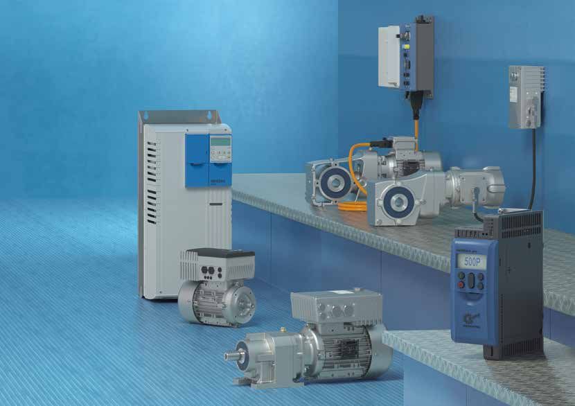
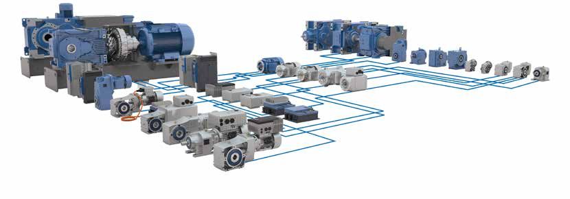
COMPLETE DRIVE SOLUTIONS
FROM A SINGLE SOURCE

                                                                                      NORD motors                      NORD gear units

 NORD drive solutions                                                  NORD drive electronics

An optimum and individual drive solution   RELIABLE                   FLEXIBLE                          INTERNATIONAL
can be created using the modular NORD      n Reliable products        n Modular products                n Globally networked organisation
system consisting of the gear unit,        n Coordinated components   n Scalable functions              n Local advice, assembly and
motor and drive electronics. Each of the
                                           n Own development and      n Large range of drive units         service
variants combine: the highest product
quality, short planning and assembly         production               n Complete drive solutions
times, high delivery availability, and a                              n Integrated customer logistics
good price / performance ratio.

 4                                                                                                                                    5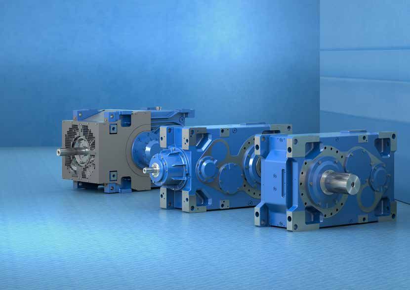
CONTENTS
              GEAR UNITS                                    Motor starter NORDAC LINK SK 155 / 175E                            64
              UNICASE helical in-line gear units       10   Motor starter NORDAC START SK 135E                                 66
GEAR UNITS

              NORDBLOC.1® helical gear units           12   NORDAC ACCESS BT and NORDCON APP                                   68
              STANDARD helical gear units              14   PROFIsafe SK TU4-PNS                                               69
              UNICASE parallel shaft gear units        16   Special options for decentralised inverters                        70
              UNICASE bevel gear units                 18   Bus systems and Industrial Ethernet                                71
              NORDBLOC.1® bevel gear units             20   Correct connection technology                                      72
              UNICASE worm gear units                  22   Mains connection and signal cables                                 73
              UNIVERSAL SI worm gear units             24   Condition monitoring for predictive maintenance                    74
              UNIVERSAL SMI worm gear units            24
MOTORS

              Gear unit options                        26   TECHNICAL INFORMATION
              MAXXDRIVE® industrial gear units         30   nsd tupH surface treatment                                         78
              Industrial gear units options            34   Overview: Energy saving directives for motors                      80
                                                            Nominal operating modes according to IEC 60034-1                   82
              MOTORS                                        International Protection Codes (IP protection class)               84
              Asynchronous motors                      38   New European ECOdesign Directive                                   85
              Synchronous motors / smooth motors       44   Installation orientations – helical gear units                     86
INVERTERS

              IE5+ synchronous motors                  46   Installation orientations – parallel shaft gear units              87
              Explosion-protected motors               48   Installation orientations – bevel gear units                       88
              Universal motors                         49   Installation orientations – worm gear units                        89
              Motor options                            50   Installation orientations – MAXXDRIVE® bevel gear units            90
                                                            Installation orientations – MAXXDRIVE® parallel shaft gear units   92
              INVERTERS                                     Installation orientations for motors and terminal boxes            94
              Frequency inverter NORDAC PRO SK 500P    54   Enquiry process                                                    95
INFORMATION

              Frequency inverter NORDAC PRO SK 500E    56
              Frequency inverter NORDAC LINK SK 250E   58
              Frequency inverter NORDAC FLEX SK 200E   60
              Frequency inverter NORDAC BASE SK 180E   62

               6                                                                                                               7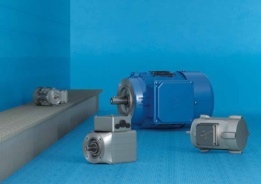
GEAR UNITS
HELICAL, PARALLEL SHAFT, BEVEL
AND WORM GEAR UNITS

 8                               9
UNICASE HELICAL IN-LINE GEAR UNITS
              The robust all-rounder

               UNICASE helical gear units (Catalogue G1000)                        UNICASE helical gear units
                                             n Foot or flange mounted versions     SK    7     2
GEAR UNITS

                                             n Long life, low-maintenance
                                             n Optimum sealing
                                             n UNICASE housing

                                             Sizes            11                                         No options
                                             Power            0.12 – 160 kW                              (solid shaft, foot mounting)
                                             Torque           10 – 26,000 Nm                       Gear stages
                                             Speed ratio      1.35 – 14,340.31:1             Housing size
MOTORS

                                                                                   Special nomenclature:
                                                                                   n SK 33 = Standard series
                                                                                   n SK 33N = UNICASE series
INVERTERS
INFORMATION

               10                           GEAR UNITS                                                          GEAR UNITS              11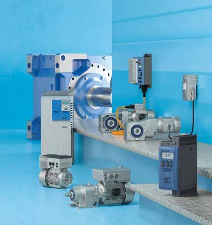
NORDBLOC.1® HELICAL GEAR UNITS
              The innovative performer

               NORDBLOC.1® helical gear units (Catalogue G1000)                       NORDBLOC.1® single stage helical gear units
                                            n Foot or flange mounted versions         SK 5    7    1   .1
GEAR UNITS

                                            n Die-cast aluminium alloy housing
                                                (cast iron housing for SK 772.1 and
                                                above)
                                            n   UNICASE housing                                                No options
                                            n   Single-stage version available for                             (solid shaft, foot mounting)
                                                high speed applications (SK x71.1)                          New design
                                            n   Long bearing life                                     Gear stages
                                                                                                 NORDBLOC design
                                                High permissible radial and axial
MOTORS

                                            n
                                                                                               Housing size
                                                forces
                                            n   Smooth-surface
                                            n   Compact design, even with IEC /       NORDBLOC.1® 2-, 3-stage helical gear units
                                                NEMA adapter
                                                                                      SK 8     7   2   .1   F
                                            n   Natural corrosion protection, even
                                                without painting
                                            Sizes             13
INVERTERS

                                            Power             0.12 – 37 kW
                                            Torque            30 – 3,300 Nm                                    B5 flange
                                            Speed ratio       1.07 – 456.77:1                              New design
                                                                                                       Gear stages
                                                                                                  NORDBLOC design
                                                                                               Housing size
INFORMATION

               12                          GEAR UNITS                                                            GEAR UNITS                   13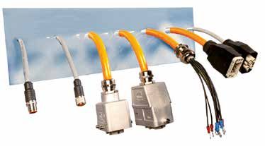
STANDARD HELICAL GEAR UNITS
              The proven classic

               STANDARD helical gear units (Catalogue G2000)                      STANDARD helical gear units (Catalogue G2000)
                                            n Foot or flange mounted versions     SK 2 5        F
GEAR UNITS

                                            n Long life, low-maintenance
                                            n Grey cast iron housing
                                            n Reinforced output side (optional)

                                            Sizes              6                                  B5 flange
                                            Power              0.12 – 7.5 kW                 Housing size
                                            Torque             50 – 700 Nm        Special nomenclature:
                                            Speed ratio        1.92 – 488.07:1    n The number of digits corresponds to the number of gear stages;
MOTORS

                                                                                    exception SK 0: these gear units have two stages
                                                                                  n A “5” at the designation end (e.g. SK 225) indicates a reinforced
                                                                                    output configuration (shaft and bearings)
INVERTERS
INFORMATION

               14                          GEAR UNITS                                                          GEAR UNITS                           15
UNICASE PARALLEL SHAFT GEAR UNITS
              Slim and powerful

               UNICASE parallel shaft gear units (Catalogue G1000)                     UNICASE parallel shaft gear units (Catalogue G1000)
                                                n Foot, flange or face mounted         SK 9      3   82 AZ SH
GEAR UNITS

                                                n Hollow or solid shaft
                                                n Compact design
                                                n UNICASE housing
                                                n Long service life
                                                                                                                    Shrink disc / cover
                                                n Low-maintenance                                               Hollow shaft / B14 flange
                                                n Quiet running – e.g. for theatre                        Parallel shaft gear units
                                                   applications                                      Gear stages
MOTORS

                                                n NORDBLOC.1® aluminium parallel                 Housing size
                                                   shaft gear units up to Size 4
                                                Sizes             15                   NORDBLOC.1® parallel shaft gear units (Catalogue G1000)
                                                Power             0.12 – 200 kW
                                                Torque            110 – 100,000 Nm
                                                                                       SK 1      2   82 .1 VX
                                                Speed ratio       4.03 – 15,685.03:1
INVERTERS

                                                                                                                    Solid shaft / foot mounting
                                                                                                             New design
                                                                                                          Parallel shaft gear units
                                                                                                     Gear stages
                                                                                                Housing size
                                                                                       Special nomenclature (NORDBLOC.1®):
INFORMATION

                                                                                       n For SK 0182.1 and SK 0282.1 the number of stages can be
                                                                                         obtained from the nomenclature (a 2- and 3-stage version is
                                                                                         available)

               16                            GEAR UNITS                                                              GEAR UNITS                        17
UNICASE BEVEL GEAR UNITS
Powerful and proven
UNICASE bevel gear units (Catalogue G1000) UNICASE bevel gear units (Catalogue G1000)
n Foot, flange or face mounted SK 90 4 2 .1 AZ
GEAR UNITS
n Hollow or solid shaft
n UNICASE housing
n High efficiency
n Robust design
n Grey cast iron housing
Hollow shaft / B14 flange
New design
n Various bearing concepts for high
Gear stages: 2 helical gear stages, 1 bevel gear stage
axial and radial load capacities
Housing size
MOTORS
n Quiet running – e.g. for theatre
Series 90
applications
Special nomenclature:
Sizes 11 n A 6 at the designation end indicates a reinforced version, 3-stage
Power 0.12 – 200 kW n A 7 at the designation end indicates a reinforced version, 4-stage
Torque 180 – 50,000 Nm (including the bevel gear stage)
Speed ratio 8.04 – 13,432.68:1
INVERTERS
INFORMATION
18 GEAR UNITS GEAR UNITS 19NORDBLOC.1® BEVEL GEAR UNITS
Power and design
NORDBLOC.1® 2-stage bevel gear units (Catalogue G1014) NORDBLOC.1® 2-stage bevel gear units (Catalogue G1014)
n Foot, flange or face mounted SK 92 3 7 2 .1 VZ
GEAR UNITS
n Hollow or solid shaft
n UNICASE housing
n Aluminium housing
n nsd tupH treatment (optional)
Solid shaft / B14 flange
n Wash-down design
New design
n High power density Gear stages: 1 helical gear stage, 1 bevel gear stage
Sizes 6 NORDBLOC design
MOTORS
Power 0.12 – 9.2 kW Housing size
Torque 50 – 660 Nm Series 92
Speed ratio 3.03 – 70:1
SK 93 6 7 2 .1 AZ
INVERTERS
Hollow shaft / B14 flange
New design
Gear stages: 1 helical gear stage,
1 bevel gear stage
NORDBLOC design
Housing size
Series 93
INFORMATION
n SK 920072.1 / SK 930072.1 have the smallest available housing
(Size 00)
20 GEAR UNITS GEAR UNITS 21UNICASE WORM GEAR UNITS
Quiet and powerful
UNICASE worm gear units (Catalogue G1000) UNICASE worm gear units (Catalogue G1000)
n Foot, flange or face mounted SK 1 2 080
GEAR UNITS
n Hollow or solid shaft
n UNICASE housing
n Soft and quiet running
n High overload capacity
Worm gear size
n High axial and radial loads (centre distance between gear and pinion 80 mm)
n Grey cast iron housing Gear stages: 1 helical gear stage, 1 worm gear stage
Sizes 6 Housing size
MOTORS
Power 0.12 – 15 kW (in combination with worm gear size)
Torque 93 – 3,058 Nm n The nomenclature can also be used for SK 02040.1
Speed ratio 4.40 – 7,095.12:1
INVERTERS
INFORMATION
22 GEAR UNITS GEAR UNITS 23UNIVERSAL WORM GEAR UNITS
Modular and flexible
UNIVERSAL SI worm gear units (Catalogue G1035) UNIVERSAL SI worm gear units (Catalogue G1035)
n Modular SK 1 SI 75 / H10
GEAR UNITS
n Universal mounting
n Life-long lubrication
n IEC version
n Aluminium housing
Helical gear pre-stage 10:1
Sizes 5 Worm gear size
Power 0.12 – 4.0 kW (centre distance between gear and pinion 75 mm)
Torque 21 – 427 Nm SI design
MOTORS
Speed ratio 5.00 – 3,000:1 Gear stages
UNIVERSAL SMI worm gear units (Catalogue G1035) UNIVERSAL SMI worm gear units (Catalogue G1035)
n Smooth-surfaces SK 1 SMI 31 AZ
n Life-long lubrication
n IEC version
INVERTERS
n Aluminium housing
n nsd tupH (optional)
Hollow shaft / B14 flange
Sizes 5 Worm gear size (31 mm)
Power 0.12 – 4.0 kW SMI design
Torque 21 – 427 Nm Gear stages
Speed ratio 5.00 – 3,000:1
INFORMATION
24 GEAR UNITS GEAR UNITS 25GEAR UNIT OPTIONS
Designation Meaning Designation Meaning
A Hollow shaft V Solid shaft
GEAR UNITS
AF Hollow shaft, B5 flange VF Solid shaft, B5 flange
AX Hollow shaft, foot mounting VL Reinforced bearings
AXF Hollow shaft, foot mounting, B5 flange VL2 Agitator version
AZ Hollow shaft, B14 flange VL3 Agitator design with "Drywell"
AZD Hollow shaft, B14 flange with torque arm VX Solid shaft, foot mounting
AZK Hollow shaft, B14 flange with torque bracket VXF Solid shaft, foot mounting, B5 flange
MOTORS
B Fastening element for hollow shaft VXZ Solid shaft, foot mounting, B14 flange
D Torque support VZ Solid shaft, B14 flange
EA Hollow shaft, splined, DIN 5480 W Drive cylinder with free drive shaft
G Rubber buffer for torque arm XF Foot mounting, B5 flange
H Cover as contact guard XZ Foot mounting, B14 flange
INVERTERS
IEC Adapter for fitting IEC standard motors
n Not all options are available for all gear units
LX Solid shaft - both sides, foot mounting n Detailed descriptions and diagrams can be found in the relevant
MK Motor bracket
catalogues
n Further options in the cited catalogues or on request (e.g. belt drives)
R Integrated backstop n Multiple options are stated in succession, e.g.: SK 2282 S H G
RLS Backstop in W adapter (hollow shaft with shrink disk, cover, rubber buffer)
S Hollow shaft with shrink disc
INFORMATION
SEK Servo adapter with clamp coupling
SEP Servo adapter with parallel key coupling
26 GEAR UNIT OPTIONS GEAR UNIT OPTIONS 27INDUSTRIAL GEAR UNITS MAXXDRIVE® HELICAL GEAR UNITS MAXXDRIVE® BEVEL GEAR UNITS MAXXDRIVE® XT BEVEL GEAR UNITS
MAXXDRIVE® INDUSTRIAL GEAR UNITS
              MAXXDRIVE® industrial gear units (Catalogue G1050)                      MAXXDRIVE® helical bevel gear units (Catalogue G1050)
              n UNICASE housing, no joints subject to torque                                                          n Universal gear units
GEAR UNITS

              n All bearing points and sealing surfaces are machined in a single                                      n 3- and 4-stage
                   operation                                                                                          n Multiple mounting and cooling
              n High precision axis alignment, quiet running                                                             options
              n Long life, low-maintenance                                                                            n Modified bearing options for high
              n Gear ratio range 5.54 to 400:1 with the same dimensions                                                  radial and axial load capacity
              n Helical and bevel gear units                                                                          n Compact design
                                                                                                                      n All installation positions
              MAXXDRIVE® helical gear units (Catalogue G1050)                                                         Sizes            11
MOTORS

                                              n Universal gear units                                                  Power            1.5 – 4,000 kW
                                              n 2- and 3-stage                                                        Torque           15,000 – 260,000 Nm
                                              n Multiple mounting and cooling                                         Speed ratio      12.61 – 30,000:1
                                                 options
                                              n Modified bearing options for high     MAXXDRIVE® XT helical bevel gear units (TI60-0011)
                                                radial and axial load capacity                                        n 2-stage
                                              n Compact design
INVERTERS

                                                                                                                      n Thermally optimised gear units
                                              n All installation positions
                                                                                                                      n Integrated high power axial fan
                                              Sizes             11                                                    n High powers with low speed ratios
                                              Power             1.5 – 4,000 kW                                        n Optimised for horizontal
                                              Torque            15,000 – 282,000 Nm                                      installation orientation
                                              Speed ratio       5.54 – 30,000:1                                       n Ideal for applications such as belt
                                                                                                                         or bucket conveyors
                                                                                                                      Sizes            7
INFORMATION

                                                                                                                      Power            1.5 – 1,500 kW
                                                                                                                      Torque           15,000 – 75,000 Nm
                                                                                                                      Speed ratio      6.14 – 22.91:1

              30               MAXXDRIVE® INDUSTRIAL GEAR UNITS                                       MAXXDRIVE® INDUSTRIAL GEAR UNITS                    31
MAXXDRIVE® INDUSTRIAL GEAR UNITS
MAXXDRIVE® industrial gear units MAXXDRIVE® drive systems (Catalogue G1050)
SK 11 2 17 AS H MS FAN 355LP/4
GEAR UNITS
Motor designation
Additional options (FAN, CC, …)
Motor adapters (IEC, NEMA, MS, ...)
Additional options (D, H, B, …)
MOTORS
Shaft and mounting options (A, V, L, …)
Type designation
07 17 07
n Complete drive systems consisting of the gear unit, motor and
Helical gear units Helical bevel gear units
Stages drive electronics
MAXXDRIVE® MAXXDRIVE® XT MAXXDRIVE®
n Wide selection of other components, e.g. couplings, brakes, etc.
2-stage 2 2 –
n Standardised solutions for rockers and base frames e.g. for belt
3-stage 3 – 4
INVERTERS
conveyors, bucket elevators, etc.
4-stage – – 5
n Systems tailored to applications, e.g. agitators, extruders, etc.
Sizes (5 – 15) n Individually adaptable
INFORMATION
32 MAXXDRIVE® INDUSTRIAL GEAR UNITS MAXXDRIVE® INDUSTRIAL GEAR UNITS 33INDUSTRIAL GEAR UNIT OPTIONS
Designation Meaning Designation Meaning
A Hollow output shaft MFT Motor base frame with turbo coupling
GEAR UNITS
AS Hollow output shaft for shrink disc MSK Motor rocker with elastic coupling
B Fastening element for hollow shaft MST Motor rocker with turbo coupling
CC Internal water cooling system MFKB Motor base frame with elastic coupling and brake
CS1 External oil cooling system MFTB Motor base frame with turbo coupling and brake
CS2 External oil-air cooling system MSKB Motor rocker with elastic coupling and brake
D Torque support MSTB Motor rocker with turbo coupling and brake
DRY “Drywell” agitator version with standard bearings NEMA Adapter for fitting B5 NEMA C flange and standard motors
MOTORS
EA Splined hollow DIN 5480 output shaft OT Oil expansion tank
ED Elastic torque arm OH Oil heater
EV Splined solid 5480 output shaft R Backstop
F Flat output flange (B14 with threaded holes) TAC Taconite sealing system
FAN Fan V Solid output shaft
FK High output flange (B5 with through holes) VL2 / KL2 Agitator version
F1 Drive flange (SK..207 / SK..307) VL3 / KL3 Agitator version with "Drywell"
INVERTERS
H/H66 Cover (contact guard) / IP66 cover VL4 / KL4 Agitator version with "True Drywell"
IEC Adapter for B5 mounting, IEC standard motors VL5 Extruder flange
L Double solid drive shaft VL6 / KL6 Agitator version with “Drywell”, without flange
LC Pressurised oil lubrication (bearings) WG First stage gear unit
LCX Pressurised oil lubrication (bearings and gears) WX Auxiliary drive unit
MC Motor bracket n Not all options / combinations are available for all gear units
MF Motor base frame n Detailed descriptions and diagrams can be found in the relevant
INFORMATION
MFB Motor base frame with brake catalogues
MS Motor swing base n Further options can be found in the cited catalogues or on request
n Multiple options are stated consecutively, e.g. SK 11217 AS H ED
MSB Motor swing base with brake
(hollow output shaft with shrink disc, cover and elastic torque arm)
MFK Motor base frame with elastic coupling
34 MAXXDRIVE® INDUSTRIAL GEAR UNITS MAXXDRIVE® INDUSTRIAL GEAR UNITS 35ELECTRIC MOTORS SYNCHRONOUS AND ASYNCHRONOUS MOTORS 36 37
ASYNCHRONOUS MOTORS
              Robust motors for all applications

               Standard motors (Catalogue M7000)                                         Switchable pole motors (Catalogue M7000)
                                               n Comply with international                                               n ISO F used according to B
GEAR UNITS

                                                   regulations and directives
                                                                                                                         Sizes              63 – 160
                                               n   Extensive options possible
                                                                                                                         Power              0.10 – 17 kW
                                               n   ISO F used according to B
                                                   (ISO H as option)                                                                        4-2, 8-2, 8-4
                                                                                                                         Number of poles
                                                                                                                                            Othres on request
                                               n   Suited for inverter operation
                                                                                                                         Protection class   IP55, optional IP66
                                               n   High overload reserves
                                                                                                                         Efficiency class   IE1
                                               Sizes               63 – 225
MOTORS

                                               Power               0.12 – 55 kW          Single-phase motors (Catalogue M7000)
                                               Number of poles     2, 4, 6, 8                                            n ISO F used according to B

                                               Protection class    IP55, optional IP66                                   n With operating and starting
                                                                                                                            capacitor and as single-phase
                                               Efficiency class    IE1, IE2, IE3
                                                                                                                            motors with Steinmetz circuit
                                                                                                                         Sizes              63 – 90
                                                                                                                         Power              0.12 – 1.5 kW
INVERTERS

                                                                                                                         Number of poles    4
                                                                                                                         Protection class   IP55, optional IP66
                                                                                                                         Efficiency class   IE1
INFORMATION

               38                             MOTORS                                                                    MOTORS                              39
ASYNCHRONOUS MOTORS
Robust motors for all applications
IEC-motors Switchable pole motors
SK 100 L H / 4 SH SK 132 M 8 /2 WU
GEAR UNITS
Silumin rotor
Anti-condensation heating Number of poles – high speed
Number of poles Number of poles – low speed
Efficiency class Power class
MOTORS
Power class Size (frame size)
Size (frame size)
n X or W in the nomenclature designates a smaller size Single-phase motors
Example: SK 250WP is a 55 kW Motor in a size 225 housing
SK 90 LB / 4 EHB1
NEMA C-FACE-motors
SK 90 L H/4 145 TC TW
INVERTERS
EHB1 – with capacitor
EAR1 – with operating and starting capacitor
EST – with Steinmetz circuit
Motor option (TW = thermostat) ECR – with operating and starting capacitor,
C-flange CUS approved
Housing size Number of poles
INFORMATION
Number of poles Power class
Efficiency class Size (frame size)
Power class
Size (frame size)
40 MOTORS MOTORS 41ASYNCHRONOUS MOTORS
Robust motors for all applications
Smooth motors (Catalogue M7010) Smooth motors
n ISO F SK 100 L H / 4 HM
GEAR UNITS
n Suited for inverter operation
n Wash-down design
n nsd tupH (optional)
n Smooth-surfaces, especially
suitable for food industry
Smooth motor type
applications
Number of poles
Sizes 71 – 100 Efficiency class
MOTORS
Power 0.12 – 2.2 kW Power class
Number of poles 4 Size (frame size)
IP66, n For non-ventilated smooth motors, the efficiency code letter is
optional IP69K H or P for Premium Efficiency (IE3)
Protection class
in combination with
the gear unit
Efficiency class IE3
INVERTERS
INFORMATION
42 MOTORS MOTORS 43SYNCHRONOUS MOTORS
High performance for your application
Standard motors (TI60-0001 and TI60-0004) Standard motors (TI60-0001 and TI60-0004)
n ISO B SK 100 T 2 / 4 Δ
GEAR UNITS
n Only for inverter operation
n Open or closed loop operation with
NORD frequency inverters
n High overload reserves
Rated speed
Sizes 80 – 100 (Δ = 3000 rpm, without = 2100 rpm)
Power 1.1 – 5.5 kW Number of poles
Stator code (depending on motor size)
Number of poles 4
MOTORS
Synchronous motors
Protection class IP55, optional IP66
Size (frame size)
Efficiency class IE4
Smooth motors (DS1007) Smooth motors (DS1007)
n ISO B SK 80 T 1 / 4 HM
n Only for inverter operation
INVERTERS
n Open or closed loop operation with
NORD frequency inverters
n Wash-down design
n nsd tupH (optional)
Smooth motor type
Sizes 80 – 100
Number of poles
Power 0.75 – 2.2 kW Stator code (depending on motor size)
Number of poles 4 Synchronous motors
INFORMATION
IP66, Size (frame size)
optional IP69K
Protection class
in combination with
the gear unit
Efficiency class IE4
44 MOTORS MOTORS 45IE5+ SYNCHRONOUS MOTORS
Efficient, hygienic and compact
IE5+ Synchronous motors (Special flyer 9012) IE5+ Synchronous motors
n Ultimate operational efficiency with SK 71 N 1 / 8
GEAR UNITS
IE5 technology
n Reduced TCO and fast ROI
n Reduced number of versions
through constant torque over a
wide speed range
n Motor can be operated worldwide Number of poles
n Flexible motor mounting: direct Rotor length (size)
mounting, NEMA, IEC
IE5+ series (non-ventilated)
MOTORS
n Especially easy to clean and
Size
corrosion-proof due to smooth
and fanless motor design –
Wash-down
n Optional motor-integrated encoder
n Optional integrated mechanical
brake
Sizes 71
INVERTERS
Power 0.35 – 1.1 kW
Number of poles 8
IP55,
optional IP66,
Protection class IP69K is possible
in combination
with a gear unit
INFORMATION
In many instances,
Efficiency class IE5 is clearly
exceeded
46 MOTORS MOTORS 47EXPLOSION-PROTECTED MOTORS NORD UNIVERSAL MOTOR
Optimally secured Can be used in the main global markets
Dust explosion-protected motors (Catalogue G2122) Universal motor (DS1005)
n Zone 21, device category 2D, n International certification
GEAR UNITS
Ex tb 125° C n CE
n Zone 22, device category 3D, n UL standard 1004
Ex tb 125° C n CSA
n Direct and IEC mounting n CCC
n EAC
Sizes 63 – 180 n ISI
Power 0.12 – 22 kW
n International energy standards
Number of poles 4 n IEC 60034-30
Protection class IP55, optional IP66 n EISA 2007
MOTORS
n EER 2010
IE2
Efficiency class n CEL / GB 18613
(80SH and higher) n MEPS AS / NZ 1359.5
Gas explosion-protected motors (Catalogue G2122) n Dual-Mode: 50 Hz and 60 Hz
n Zone 1, device category 2G, n Four different operating points
Exe T3
n Zone 2, device category 3G,
INVERTERS
Exn T3
n Direct and IEC mounting
Sizes 63 – 180
Power 0.12 – 22 kW
Number of poles 4
Protection class IP55, optional IP66
IE2 Sizes 63 – 225
Efficiency class
INFORMATION
(80SH and higher)
Power 0.12 – 45 kW
n Motors compliant with NEC explosion protection HazLoc and IECEX Number of poles 4
are also available
n Further information about European explosion protection is given in Protection class IP55, optional IP66
Manual Part No. 6091602 Efficiency class IE3 / Premium
48 MOTORS MOTORS 49MOTOR OPTIONS
Designation Meaning Designation Meaning
BRE + Brake / brake torque + sub-options MS Motor plug connection
GEAR UNITS
DBR + Double brake + sub-options EKK One-piece terminal box
RG * Rust protected version KKV Encapsulated terminal box
SR * Dust and rust protected version FEU Humidity protection insulation
IR * Current relay TRO Tropical protection insulation
FHL * Lockable manual release MOL Dairy version
HL Manual release Regulation – Vereinigung Industrieller Kraftwirtschaft
VIK
MIK Microswitch [Association of the Industrial Power Industry]
F External fan
MOTORS
AS55 * Outdoor installation
RLS Backstop
BRB Anti-condensation heater / Brake
NRB1/2 Noise-reduced brake MG Magnetic incremental encoder
ERD External earthing terminal SL Sensor bearings
TF Thermistor, PTC resistor IG Incremental encoder
TW Temperature sensor, bi-metal IG.P Incremental encoder with plug connector
SH Anti-condensation heating IG.K Incremental encoder with terminal box
INVERTERS
WU Silumin rotor AG Absolute encoder
Z Additional flywheel, cast iron fan *not for DBR
WE + Second shaft end n Not all options are available for all motors
HR Hand wheel n Detailed descriptions and drawings of the options can be found in M7000
n Further options (e.g. motor plug connection, 2xTF etc.) on request
RD Protective shield
RDT Protective shield, textile fan cowl
RDD Double fan cowl
INFORMATION
AS66 Outdoor installation
OL Without fan
OL/H Without fan, without fan cowl
KB Closed condensation drain hole
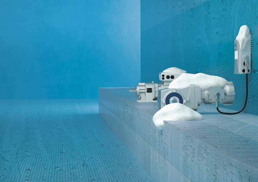
50 MOTOR OPTIONS MOTOR OPTIONS 51DRIVE ELECTRONICS FREQUENCY INVERTERS AND MOTOR STARTERS 52 53
NORDAC PRO SK 500P
              Frequency inverters – for versatile use

               NORDAC PRO SK 500P (Catalogue E3000)                                  NORDAC PRO SK 500P
                                  n Universal drive in various basic versions, can   SK 500P 551 340   A
GEAR UNITS

                                     be modularly extended
                                  n Precise current vector control with high
                                     overload reserves for operating asynchronous
                                     and synchronous motors
                                  n HTL encoder interface for closed-loop servo
                                     mode and POSICON positioning function even
                                     in the basic SK 500P device
                                  n Universal interface for real-time Ethernet
                                                                                                           EMC line filters:
                                     PROFINET, ETHERCAT, ETHERNET IP and                                   A = Class A1 (C2)
                                     POWERLINK                                                          Mains voltage:
MOTORS

                                  n CANopen as series equipment                                         x23 = 230 V; x40 = 400 V
                                  n Drive profile DS402 for CANopen, ETHERCAT                        Number of mains phases:
                                     and POWERLINK                                                   1xx = 1-phase; 3xx = 3-phase
                                  n integrated PLC for drive-related functions,
                                                                                                  Digits before decimal point for power:
                                     even in the basic device
                                  n TTL encoder interface and optional universal                  0 = 0.xx; 1 = 0x.x0; 2 = 0xx.0; 3 = 0xx0.0
                                     encoder interface                                          Rated power (xx):
                                  n Optional: Safe Stop with "Safe Torque Off"                  250 = 0.25 kW … 551 = 5.5 kW etc.
INVERTERS

                                     (STO) and "Safe Stop 1" (SS1) according to             Frequency inverter type: SK 500P, SK 510P, SK 530P, SK 550P
                                     EN 61800-5-2
                                  n MicroSD Card
                                  n USB interface for connection to NORDCON,
                                     may also be used without a power supply
                                  n Compact slim design, can be mounted directly
                                     adjacent to other components
                                  n in Size 1 and 2 all terminals are implemented
                                     as plug connections, including the power
INFORMATION

                                     connections for the mains and the motor
                                  Sizes            3
                                                   1~ 200 – 240 V
                                   Voltage
                                                   3~ 380 – 480 V
                                  Power            0.25 – 5.5 kW
               54                    DRIVE ELECTRONICS                                                     DRIVE ELECTRONICS                        55
NORDAC PRO SK 500E
Frequency inverters – for versatile use
NORDAC PRO SK 500E (Catalogue E3000) NORDAC PRO SK 500E
n Maximum functionality SK 500E 113 340 A
GEAR UNITS
n Sensorless current vector control (ISD control)
n Multi-encoder interface
n PLC functionality for drive-integrated
functions, SK 520E and higher
n Optional: POSICON positioning SK 530E and
higher EMC line filters:
n Optional: Safe stop with “Safe Torque Off” A = Class A1 (C2)
(STO) and “Safe Stop 1” (SS1) as per
MOTORS
Mains voltage:
EN 61800-5-2 (for SK 510E and SK 530E)
x12 = 115 V; x23 = 230 V; x40 = 400 V
n ASM and PMSM motor operation Number of mains phases:
n Energy-saving function 1xx = 1-phase; 3xx = 3-phase
n High overload reserves (200 %) for all power Digits before decimal point for power:
ratings up to 160 kW 0 = 0.xx; 1 = 0x.x0; 2 = 0xx.0; 3 = 0xx0.0
n Many field bus- and Industrial Ethernet-based Rated power (xx):
bus systems 751 = 7.5 kW; 113 = 110 kW etc.
INVERTERS
n Optional: CANopen integrated in SK 511E and Frequency inverter type: SK 500E ... SK 545E
higher
n Integrated Class C1 line filter
n Alternative cooling systems, e.g. “Cold Plate”
n IP20 control cabinet installation
Sizes 11
1~ 110 – 120 V
INFORMATION
1~ 200 – 240 V
Voltage
3~ 200 – 240 V
3~ 380 – 480 V
Power 0.25 – 160 kW
56 DRIVE ELECTRONICS DRIVE ELECTRONICS 57NORDAC LINK SK 250E
Frequency inverters – easy to install
NORDAC LINK SK 250E (Catalogue E3000) NORDAC LINK SK 250E
n Protection class IP65 (< 2.2 kW), IP55 SK 250E FDS 301 340 A
GEAR UNITS
(all devices with fan or option FANO) SK 250E FDS 301 340 A
n Simple commissioning and installation in the
field
n All I/O, bus interface and power connections
in plug-in version for easy commissioning and
maintenance
n Extensive options e.g. key operated EMC line filters:
maintenance switch, push buttons, A = Class A1 (C2)
potentiometers Mains voltage:
MOTORS
n PLC functionality for drive-integrated x40 = 400 V
functions Number of mains phases:
n Functions compatible with modular 3xx = 3-phase
NORDAC FLEX Digits before decimal point for power:
n AS-Interface 0 = 0.xx; 1 = 0x.x0
n Safe stop with “Safe Torque Off” (STO) and Rated power (xx):
“Safe Stop 1” (SS1) as per EN 61800-5-2
301 = 3 kW
INVERTERS
n Many field bus- and Industrial Ethernet-based
NORDAC LINK FDS
bus systems
Frequency inverter type: SK 250E ... SK 280E
n ASM and PMSM motor operation
n Local or remote control n FDS = Field Distribution System
Sizes 3
Voltage 3~ 380 – 500 V
Power 0.37 – 7.5 kW
INFORMATION
58 DRIVE ELECTRONICS DRIVE ELECTRONICS 59NORDAC FLEX SK 200E
Frequency inverters – for flexible use
NORDAC FLEX SK 200E (Catalogue E3000) NORDAC FLEX SK 200E
n Sensorless current vector control SK 200E 550 340 A (-C)
GEAR UNITS
(ISD control)
n PLC functionality for drive-integrated
functions
n Integrated POSICON positioning control
n Safe stop with “Safe Torque Off” (STO) and Protection class:
“Safe Stop 1” (SS1) as per EN 61800-5-2 without = IP55 (standard)
n ASM and PMSM motor operation C = IP66
n Energy-saving function EMC line filters:
MOTORS
n Motor or wall mounting A = Class A1 (C2)
n IP55 (optional IP66) Mains voltage:
n AS-Interface integrated in SK 22xE and x12 = 115 V; x23 = 230 V;
SK 23xE
x40 = 400 V
n Many field bus- and Industrial Ethernet-based
Number of mains phases:
bus systems
1xx = 1-phase; 3xx = 3-phase
n Extensive selection of plug connectors for
control and power cable connections Digits before decimal point for power:
INVERTERS
0 = 0.xx; 1 = 0x.x0; 2 = 0xx.0
n ATEX Zone 22, Category 3D (Sizes 1 – 3)
Rated power (xx):
n POSICON with absolute encoder
550 = 0.55 kW ... 222 = 22 kW etc.
Sizes 4 Frequency inverter type: SK 200E ... SK 230E and
1~ 110 – 120 V SK 205E ... SK 235E
1~ 200 – 240 V
Voltage
3~ 200 – 240 V
3~ 380 – 500 V
INFORMATION
Power 0.25 – 22 kW
60 DRIVE ELECTRONICS DRIVE ELECTRONICS 61NORDAC BASE SK 180E
Frequency inverters – economical in use
NORDAC BASE SK 180E (Catalogue E3000) NORDAC BASE SK 180E
n Sensorless current vector control SK 180E 750 340 B (-C) XXX
GEAR UNITS
(ISD control)
n PLC functionality for drive-integrated
functions
n Operation on standard RCD possible,
leakage currentNORDAC LINK SK 155E
Motor starters – for economical operation
NORDAC LINK SK 155E / 175E (Catalogue E3000) NORDAC LINK SK 155E / 175E
n All I/O, bus interface and power connections SK 175E FDS 301 340 A
GEAR UNITS
in plug-in version for easy commissioning and
maintenance
n Extensive options e.g. key switch
maintenance switch
n PLC functionality for drive-integrated
EMC line filters:
functions
A = Class A1 (C2)
n Wear-free fully electronic starting with
reversing function Mains voltage:
Functions compatible with modular x40 = 400 V
MOTORS
n
NORDAC START Number of mains phases:
n Protection class IP65 3xx = 3-phase
n Simple commissioning Digits before decimal point for power:
n AS-Interface or PROFIBUS can be used 1 = 0x.x0
n Field installation Rated power (xx):
n Can be parameterised on-site 301 = 3 kW
NORDAC LINK FDS
Sizes 1
INVERTERS
Frequency inverter type: SK 155E (unidirectional),
Voltage 3~ 380 – 500 V SK 175E (bidirectional)
Power 0.12 – 3 kW
n FDS = Field Distribution System
INFORMATION
64 DRIVE ELECTRONICS DRIVE ELECTRONICS 65NORDAC START SK 135E
Motor starters – for economical operation
NORDAC START SK 135E (Catalogue E3000) NORDAC START SK 135E
n Motor starter with soft start and reversing SK 135E 301 340 B ASI C(-NSD) for IP69K
GEAR UNITS
function
n Integrated brake rectifier to control a brake
(BRE)
n PROFIBUS or AS-Interface integrated
n Wall or motor mounting Protection class:
n IP55 (optional IP66 and IP69K) Standard = IP55
n nsd tupH treatment (optional) C = IP66
Communication:
Integrated line filter
MOTORS
n
ASI = AS-Interface
n 2 digital inputs, 2 digital outputs
PBR = PROFIBUS-Interface
n Temperature sensor input (TF+ / TF-) EMC line filters: Class B = Class C1
n RS232 interface Mains voltage: x23 = 230 V; x40 = 400 V
n ATEX Zone 22, Category 3D Number of mains phases:
n Electronic starter switches without wear 3xx = 3-phase
n Reduced mechanical wear due to reduced Rated power (xx):
INVERTERS
start-up torque 301 = 3.0 kW or 751 = 7.5 kW
Frequency inverter type: SK 135E or SK 175E
Sizes 2
3~ 200 – 240 V
Voltage
3~ 380 – 500 V
Power 0.12 – 3 kW or up to 7.5 kW
INFORMATION
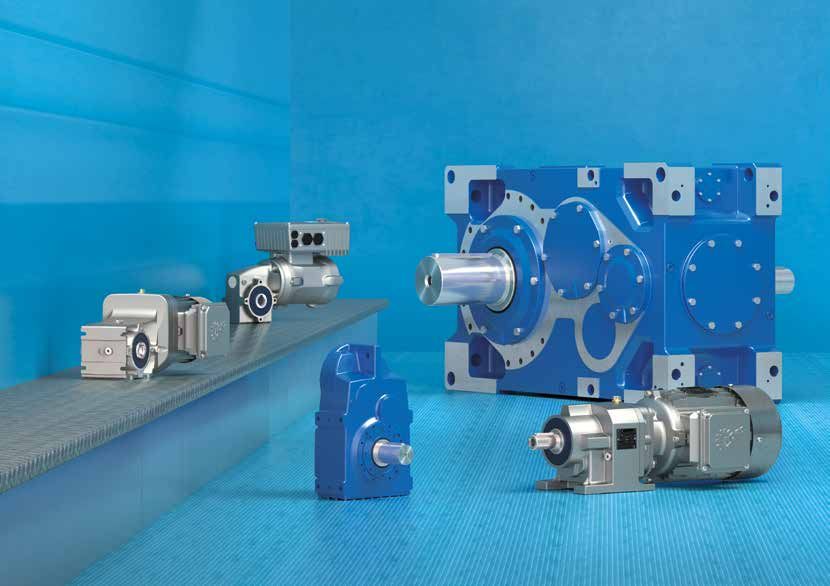
66 DRIVE ELECTRONICS DRIVE ELECTRONICS 67NORDAC ACCESS BT / NORDCON APP PROFIsafe – SK TU4-PNS
NORDAC ACCESS BT Safe Motion PROFIsafe via PROFINET
n Stand-alone parameter memory with module SK TU4-PNS
GEAR UNITS
Safety functions for drives according to IEC 61800-5-2
n Bluetooth interface for inverter and
NORDCON APP V V V
n Data transfer to PC via USB
n Can be plugged in or disconnected t
during operation t1 t2 t t1 t2 t t1 t2
Safely Limited Speed (SLS) Safe Speed Range (SSR) Safe Direction (SDI)
NORDCON APP n PLe (Performance Level)
V V
Cat. 4 according to ISO 13849-1
MOTORS
n Dashboard based visualisation for
SIL 3 (Safety Integrity Level)
drive monitoring and fault diagnosis
n
as per IEC 62061
n Parameterisation with Help function fe
d sa
efine tion
and rapid access to parameters t1 t2 t t1 t2 t er-d
+ Us configu
ra
Safe Operation Stop (SOS) Safe Speed Measurement (SSM) I/O
n Individually configurable
oscilloscope function for drive
analysis n Simple implementation of safe responses
n Backup and recovery function for for NORDAC FLEX decentralised inverters
INVERTERS
simple handling of drive parameters n Comprehensive safety for reliable
operation of plant and machinery
n Functional safety with a single network
cable
n Minimum wiring effort
n Global availability of fail-safe machine data
INFORMATION
68 DRIVE ELECTRONICS DRIVE ELECTRONICS 69SPECIAL OPTIONS FOR BUS SYSTEMS AND
DECENTRALISED INVERTERS INDUSTRIAL ETHERNET
Bus systems / Industrial Ethernet
Plug connections
All connections designed for
GEAR UNITS
simple handling, so that drives
Sensors / Process data
can be very conveniently
configured and installed. ETHERNET
n Simple Plug-and-Play with all POWERLINK
common connection plugs
n Mains and motor output plugs
n M12 plugs for sensors and
encoders
MOTORS
n Pre-assembled cables
Local control
Switches and keys are located
directly on the drives and enable
INVERTERS
direct starting and stopping as
well as mode switching.
n Mains switch
n Selector switch for local or
remote control
n Start / Stop and Forward /
Reverse switch
INFORMATION
Actuators
70 DRIVE ELECTRONICS OPTIONS DRIVE ELECTRONICS OPTIONS 71CORRECT CONNECTION TECHNOLOGY
Pre-assembled
NORD DRIVESYSTEMS supplies an extensive range of connection and n Cables for motor and frequency inverter connection
control cables. n Mains connection and Daisy chain cables
n Signal and brake resistor cables
GEAR UNITS
n Depending on the version, connecting cables include power
connection cables (mains and motor) and if necessary cables for SK CE HQ8-K MA H10E-M1B 3_OM
thermistors as well as 24 V DC control voltage
Labelling for various combinations
n Control cables are exclusively used for transmitting control signals 3_OM = Length 3 m
(encoder, bus, I/O signals) S5UL = Special solution 3 m and
UL certification, note: only permissible for
Connection and control cables are supplied pre-assembled. They are plug connectors
available in various lengths and can be optionally provided with open Cable end side 2: version and material labelling
ends or plug connectors. Connection cables are certified for global use H10E = HAN 10E plug connector M1B = One metal lock
MOTORS
according to the relevant IEC and UL standards. otherwise identical to M2B = Two metal locks
cable end side 1 Note: material labelling
is only permissible for
plug connectors
Cable category
LE = Line connection
LA = Daisy chain mains connection
MA = Motor connection
BRE = Brake resistor
BRW5 = Brake resistor
INVERTERS
SYSM = System bus
AG = Absolute encoder
IG = Encoder without zero track
... C = Combination encoder (AG / IG)
IG0 = Encoder with zero track
Cable end side 1: version and material labelling
HQ8 = HAN Q8/0 plug connector K = Plug connector with plastic housing
HQ4 = HAN Q4 plug connector M = Plug connector with metal housing
(w/o = without) Note: material labelling is only
INFORMATION
HQ42 = HAN Q4/2 plug connector permissible for plug connectors
(24 V DC)
OE = Open ends
A5F = M12 A-coded 5-pin female
B4M = M12 B-coded 4-pin male
Cable extension
72 DRIVE ELECTRONICS OPTIONS DRIVE ELECTRONICS OPTIONS 73CONDITION MONITORING FOR
PREDICTIVE MAINTENANCE
For CONDITION MONITORING, drive and status data are recorded Temperature curve of the oil in the gear unit
periodically or continuously in order to optimise the operational safety
and efficiency of machines and plants. CONDITION MONITORING
GEAR UNITS
can provide major information for PREDICTIVE MAINTENANCE. The I f T t
1 0 0 1 1 1 1 1 1 0 1 1 1 1 1 1 1 1 1 1 0 1 1
111101111100
Excessive oil temperature [K]
objective is to maintain machines and plants proactively, to reduce
0 1 0 1 1 1 1 1 1 0 0 1 1 1 1 1 1 0 1 1
downtimes and to increase the efficiency of the entire plant.
The INDUSTRIAL INTERNET of THINGS (IIoT) focuses on internet
usage in industrial processes and procedures. IIoT aims at increasing
the operational efficiency, reducing costs and speeding up processes.
Sensors and sensor data play a central role to provide the basis for
CONDITION MONITORING and PREDICTIVE MAINTENANCE.
MOTORS
n CONDITION MONITORING solutions for PREDICTIVE ––– Measured oil temperature
MAINTENANCE systems integrated into the frequency inverter ––– Calculated oil temperature
n System is IIoT / Industry 4.0 READY!
n Available for decentralised and control cabinet solutions Time [h]
Further information in special flyer S9091 Sensors
n Virtual sensors – the PLC can calculate information such as the
optimal oil change time
n Interface for digital / analogue sensors
INVERTERS
Communication interfaces
n Threshold values or general status information can be communicated
externally (via normal Industrial Ethernet dialects)
Integrated PLC
n Local pre-processing of data with the integrated PLC
n Pre-processing of threshold values
INFORMATION
74 DRIVE ELECTRONICS OPTIONS DRIVE ELECTRONICS OPTIONS 75TECHNICAL INFORMATION nsd tupH surface protection Energy saving directives for motors Nominal operating modes International Protection Codes Installation orientations Enquiry process
Sealed Surface Conversion System
NORD geared motors and electronics (SK 1xxE) with Tests performed on surface treated aluminium housing
are ideal for use in extreme ambient conditions: components:
GEAR UNITS
n ASTM D714 Blister formation
n Easy to clean surfaces n ASTM D610-08 Corrosion
n Resistant to acids and alkalis (wide pH range) n ASTM D1654-08 Scratching
n No blistering, even if damaged n ASTM B117-09 Salt spray test
n Cannot flake n ASTM D3170 Gravelometer test
n Corrosion resistant – prevents contact corrosion n DIN EN ISO 9227 Salt spray mist test
n Alternative to stainless steel n DIN EN ISO 2409 Cross-cut test
n Complies with FDA Title 21 CFR 175.300
n Free from chromates Stainless
Overview of advantages Paint nsd tupH
steel
MOTORS
The complete solution for extreme conditions:
n Surface treated housing components No flaking possible –– ++ ++
n DIN and standard components made from stainless steel
n Wash-down housing (gear unit and motor) Corrosion resistant + ++ ++
n Stainless steel shafts
n Special shaft sealing rings
Costs + ––
n Food compatible oil
Weight ++ – ++
INVERTERS
for extreme conditions: Available products + – +
n Food and beverage industry
n Dairies Thermal conductivity + – +
n Pharmaceutical industry
n Water and waste water plants + advantageous, ++ very advantageous, neutral,
n Car wash equipment – disadvantageous, – – very disadvantageous
n Offshore and coastal areas
n Chemical cleaning Products available with nsd tupH:
(Wash-down, wide pH range)
INFORMATION
n Helical gear units
n Bevel gear units
n Worm gear units
n Smooth motors
n NORDAC START and NORDAC BASE electronics
78 TECHNICAL INFORMATION TECHNICAL INFORMATION 79OVERVIEW OF ENERGY SAVING
DIRECTIVES FOR MOTORS
Voltage / Number of Regulation for
Country Power range Regulations / Directives Planning / remarks
frequency poles min. energy efficiency
EG 640/2009
GEAR UNITS
Europe, Switzerland 50 – 1000 V EG 4/2014 New Ecodesign Directive for the EU as of 2021
0.75 – 375 kW 2–6 IE3
and Turkey 50 / 60 Hz 2009/125/EG or 2023, see page 85
Ecodesign Directive
< 600 V 1 – 500 HP
USA 2–8 EISA 2007 / EISA 2014 NEMA Premium (IE3) Extension to sizes NEMA 42-48-56
60 Hz (0.75 – 375 kW)
< 600 V 1 – 500 HP
Canada 2–8 EER 2017 NEMA Premium (IE3) No update planned
50 / 60 Hz (0.75 – 375 kW)
< 1000 V GB 18613-2012
China 0.75 – 375 kW 2–6 Grade 3 (IE2) IE3 introduction has been postponed
50 Hz GB 25958-2010
Lei No 10.295
Decreto No 4.508
< 1000V
MOTORS
Brazil 0.75 – 185 kW 2–8 Portaria Interministerial Alto Redimento Plus (IE3) No update planned
50 / 60 Hz
Nº 1, DE 29 DE JUNHO
DE 2017
< 600 V 1 – 500 HP
Mexico 2–8 NOM-016-ENER-2010 NEMA Premium (IE3) No update planned
60 Hz (0.75 – 375 kW)
< 600 V
Columbia 0.18 – 373 kW 2–8 Resolution no. 1012:2015 IE2 IE3 > 7.5 kW from August 2020
60 Hz
< 690 V
Chile 0.75 – 7.5 kW 2–6 NCh 3086 of 2008 IE2 No update planned
50 Hz
< 1000 V
Ecuador 0.746 – 373 kW 2–8 Resolucion No. 17 524:2017 IE2 No update planned
INVERTERS
60 Hz
IE2 requirements according to AS / NZS 1359.5
Australia < 1100 V
0.73 – 185 kW 2–8 AS / NZS 1359.5 : 2004 MEPS 2 “E2” are to some extent more stringent than the IE2
New Zealand 50 Hz
regulations according to IEC!
< 1000 V Gazette of India No.
India 0.12 – 375 kW 2–8 IE2 No update planned
50 Hz 3144/2018
< 600 V
Soth Korea 0.75 – 375 kW 2–8 MKE-2015-28 IE3 No update planned
60 Hz
< 1000 V Energy Conservation Act
Singapore 0.75 – 375 kW 2–6 IE3 No update planned
50 Hz (ECA) 2013
INFORMATION
< 600 V
Taiwan 0.75 – 200 kW 2–8 CNS 14400 (MEPS) IE3 No update planned
60 Hz
< 1000 V
Japan 0.75 – 375 kW 2–6 JIS C 4213 (2014) IE3 No update planned
50 / 60 Hz
50 – 1000 V
Saudi Arabia 0.75 – 375 kW 2–8 SASO 2893:2018 IE3 No update planned
60 Hz
80 TECHNICAL INFORMATION TECHNICAL INFORMATION 81NOMINAL OPERATING MODES
ACCORDING TO IEC 60034-1
Motor load
GEAR UNITS
Constant Variable
No With Intermittent
time limit time limit (regular) Fluctuating
MOTORS
Interrupted operation Continuous operation
Load Start Start Load Start Load 1 Load Load 1
Stop Load Load Idling Load Load 2 and Load 2
speed
INVERTERS
Stop Brakes Brakes …
Stop
S1 S2 S3 S4 S5 S6 S7 S8 S9 S10
n In case of S2 the operating time in minutes must be stated as follows:
INFORMATION
“S2 15 minutes”
n In case of S3, S4, S5 and S6 the operating time in minutes must be
stated as follows: „S3 40 %“, i.e.: 40 % operating time on the basis of
10 minutes
82 TECHNICAL INFORMATION TECHNICAL INFORMATION 83INTERNATIONAL PROTECTION CODES NEW EUROPEAN
"IP PROTECTION CLASS" (IEC 60529) ECODESIGN DIRECTIVE
Protection against foreign Protection against water The European Union has continued to develop the existing Ecodesign
Digit 1 Digit 2 Directive 2009/125/EG. In future, the present exceptions will be greatly
bodies (humidity)
restricted and motors for special ambient conditions, e.g. explosion
GEAR UNITS
0 No protection 0 No protection
protection areas will also have to comply with these new energy
1 Protected against solid foreign 1 Protection against dripping water efficiency classes. Establishment of these increased requirements will
bodies with diameter above take place in several stages:
50 mm
JULY 2021
2 Protected against solid foreign 2 Protection against dripping water
bodies with diameter above if the housing is inclined by up n IE3 for 0.75 – 1,000 kW and IE2 for 0.12 – 1.0 mm
no details of protection against moisture) 8 Protection against permanent
immersion
n For IPX7 the immersion depth and the
immersion time must also be stated 9K Protection against water for high
n Up to IPX6 the lower protection classes (ac- pressure water jet and steam
are included cording cleaning, specifically for road
to ISO vehicles
INFORMATION
20653)
84 TECHNICAL INFORMATION TECHNICAL INFORMATION 85INSTALLATION ORIENTATIONS INSTALLATION ORIENTATIONS
HELICAL GEAR UNITS PARALLEL SHAFT GEAR UNITS
M2
GEAR UNITS
M6
M6
M2
M1
M1
M5 M5
MOTORS
M4
M4
INVERTERS
M3
M3
INFORMATION
86 TECHNICAL INFORMATION TECHNICAL INFORMATION 87INSTALLATION ORIENTATIONS INSTALLATION ORIENTATIONS
BEVEL GEAR UNITS WORM GEAR UNITS
M6
GEAR UNITS
M2
M1
M5
MOTORS
M4
INVERTERS
M3
INFORMATION
88 TECHNICAL INFORMATION TECHNICAL INFORMATION 89INSTALLATION ORIENTATIONS
MAXXDRIVE® BEVEL GEAR UNITS
M6 M6 M3
GEAR UNITS
M2 M2
M1
M5 M5
MOTORS
M4 M4
INVERTERS
M3
M1
INFORMATION
90 TECHNICAL INFORMATION TECHNICAL INFORMATION 91INSTALLATION ORIENTATIONS
MAXXDRIVE® PARALLEL SHAFT GEAR UNITS
M6 M6 M3
GEAR UNITS
M2 M2
M1
M5 M5
MOTORS
M4 M5
INVERTERS
M3
M1
INFORMATION
2-stage gear unit installation orientations 3-stage gear unit installation orientations
92 TECHNICAL INFORMATION TECHNICAL INFORMATION 93INSTALLATION ORIENTATIONS
FOR MOTORS AND TERMINAL BOXES ENQUIRY PROCESS
IM B5 myNORD
The online product configurator in the myNORD (www.mynord.com)
GEAR UNITS
customer portal enables convenient selection of the drive unit. Ex drives
including options can also be selected for
IM B3
n Precise configuration,
n Direct generation of CAD- data (3D models, dimensioned drawings,
IM V1 IM V3
outline drawings),
n Creation of offers online.
IM B7 IM V6
It must be emphasised that the configurator indicates whether or not a
selected drive unit is Ex compliant. Price information as well as an
IM B14
enquiry / order form are also included.
MOTORS
If configuration with myNORD is not possible, an enquiry form is available
IM V5 IM B6 (www.nord.com > Forms > General Enquiry Form) Selection of the drive
unit and checking of conformity will then be carried out by your technical
contact partner.
IM V18 IM V19
IM B8
INVERTERS
3 2
1 1
Configurator for precisely tailored Generate offer with purchase prices
4 2 drives
3 1
INFORMATION
1 1
1
4
Generate CAD data, (3D models, Track order status
The nomenclature is also available as a poster (Part No. 6091985) dimension sheets, outline drawings)
94 TECHNICAL INFORMATION TECHNICAL INFORMATION 95NOTES 96 97
NOTES

98      99
www.nord.com/locator

Headquarters:
Getriebebau NORD GmbH & Co. KG
                                        Part. No. 6091502 / 1320

Getriebebau-Nord-Str. 1
22941 Bargteheide, Germany
T +49 4532 289 0, F +49 4532 289 2253
info@nord.com
Member of the NORD DRIVESYSTEMS Group
You can also read