Green air-conditioning - By Martijn Wuis, Maarten Wuister Bart Janssen
←
→
Page content transcription
If your browser does not render page correctly, please read the page content below
Green air-conditioning

   By Martijn Wuis, Maarten Wuister
   Bart Janssen

                                      1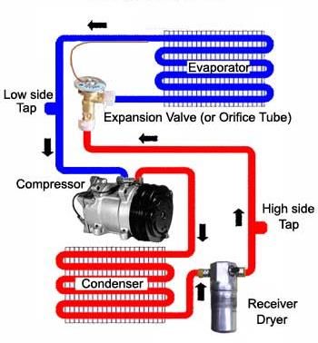
Contents
Contents .................................................................................................................................................. 2
01. Explanation of relevant terms, expressions and abbreviations ........................................................ 3
1. Introduction:........................................................................................................................................ 4
2. Different types of Marine HVAC systems ............................................................................................ 5
   2.1 General working principles ............................................................................................................ 5
   2.2 High Pressure System vs. Low Pressure system ............................................................................ 6
   2.3 Number of Pipes ............................................................................................................................ 7
   2.4 Centralised units ............................................................................................................................ 7
   2.5 Decentralised units ........................................................................................................................ 8
   2.6 Cruise ship HVAC ........................................................................................................................... 8
3. The HVAC Systems ............................................................................................................................... 9
   3.1 Constant airflow with Reheating (CAV + Reheating)..................................................................... 9
   3.2 Variable Airflow (VAV) ................................................................................................................. 10
   3.3 Variable Airflow with reheating (VAV + Reheating) .................................................................... 11
   3.4 Twin Duct..................................................................................................................................... 12
   3.5 Airflow regulated with water circulation (Smart Air) .................................................................. 12
   3.6 Air recirculation with reheating and water circulation (CFAF) .................................................... 13
4. Comparison Table .............................................................................................................................. 15
5.Future of HVAC ................................................................................................................................... 16
   5.1 The environment .................................................................... Fout! Bladwijzer niet gedefinieerd.
   5.2 Efficiency ................................................................................ Fout! Bladwijzer niet gedefinieerd.
       5.2.1 High Efficiency Air Conditioning ...................................... Fout! Bladwijzer niet gedefinieerd.
       5.2.2 Theoretical maximum...................................................... Fout! Bladwijzer niet gedefinieerd.
       5.2.3 Solar Air Conditioning ...................................................... Fout! Bladwijzer niet gedefinieerd.
   5.3 The Montreal Protocol ........................................................... Fout! Bladwijzer niet gedefinieerd.
   5.4 Cooling Liquids........................................................................ Fout! Bladwijzer niet gedefinieerd.
       5.4.1 Refrigerant R410A ........................................................... Fout! Bladwijzer niet gedefinieerd.
       5.4.2 Physical properties R410A .............................................. Fout! Bladwijzer niet gedefinieerd.
6. Recommendations/Conclusion .................................................... Fout! Bladwijzer niet gedefinieerd.
   How does air-conditioning work on cruise ships?........................ Fout! Bladwijzer niet gedefinieerd.
   What types of systems are available for air-conditioning? .......... Fout! Bladwijzer niet gedefinieerd.
       What are the differences between the air-conditioning systems? ................. Fout! Bladwijzer niet
       gedefinieerd.

                                                                                                                                                           2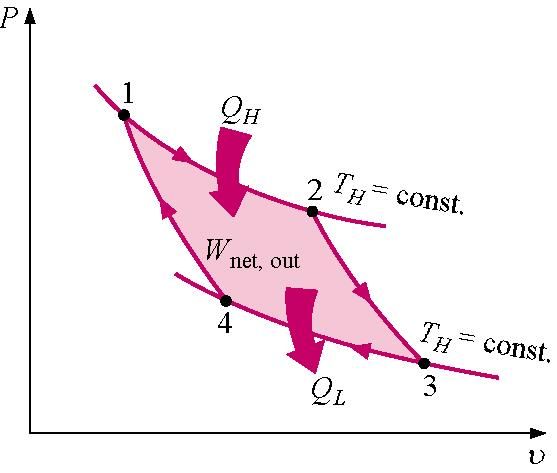
What differences are there regarding environmental impact?Fout! Bladwijzer niet gedefinieerd.
       What differences are there regarding efficiency? ................... Fout! Bladwijzer niet gedefinieerd.
       What differences are there regarding the purchasing costs? .. Fout! Bladwijzer niet gedefinieerd.
       How dependable are the systems? .......................................... Fout! Bladwijzer niet gedefinieerd.
       How suitable are the systems for use on cruise ships? ............ Fout! Bladwijzer niet gedefinieerd.
       In what direction are improvements on air-conditioning systems currently sought by air-
       conditioning suppliers? ............................................................ Fout! Bladwijzer niet gedefinieerd.
       How is/can waste energy from the main-engines (be) used for air-conditioning systems?.....Fout!
       Bladwijzer niet gedefinieerd.
   General Conclusion ...................................................................... Fout! Bladwijzer niet gedefinieerd.
7. References ......................................................................................................................................... 27
   Appendix 1......................................................................................................................................... 27
   Appendix 2.................................................................................... Fout! Bladwijzer niet gedefinieerd.

01. Explanation of relevant terms, expressions and abbreviations
HVAC:                               Heating Ventilation Air-conditioning Cooling

CFC: ChloroFluoroCarbon ( Cooling agent)

HCFC: HydroChloroFluroCarbon ( Cooling agent)

                                                                                                                                                        3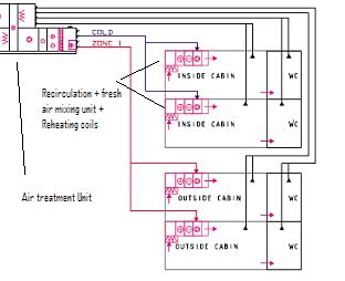
:
1. Introduction

As part of our second year school project we are commissioned to write a scientific report
about our subject “Cruise ship Air-conditioning”. Our main research subject is the energy
efficiency of the Heating, Ventilation and air conditioning systems onboard these ships. It is
an interesting subject because of the high energy consumption of these systems and the
amount of savings that can be gotten from making these systems more efficient. The
purpose of this report is to inform the reader about the different systems currently used and
the advantages and disadvantages of these systems, and how to choose which system would
be best to install in cruise ships. To achieve this we will answer and explain the following
questions:

    - How does air-conditioning work on cruise ships?

    - What types of systems are available for air-conditioning?

        - What are the differences between the air-conditioning systems?
        - What differences are there regarding environmental impact?
        - What differences are there regarding efficiency?
        - What differences are there regarding the purchasing costs?
        - How dependable are the systems?
        - How suitable are the systems for use on cruise ships?
   - In what direction are improvements on air-conditioning systems currently sought by air-
conditioning suppliers?

    - How is/can waste energy from the main-engines (be) used for air-conditioning systems?

Furthermore we will briefly look into where the latest improvements to HVAC systems are
currently made, as well as how the waste energy from the engines could be used to power
the HVAC systems. Or other better solutions that have not yet been used on cruise ships.

To achieve these goals we will first discuss the different types of HVAC Systems. Then we will
give a detailed view of cruise ship systems regarding the stated aspects. After that we make
a comparison between the systems. Hereafter we will give a short look at the future
improvements, with suggestions for discussion and further investigation. We will close with
the conclusions drawn based on our findings.

For this report the information will be sought in proper books and internet sites. Also will the
imtech company be contacted to receive current detailed information on HVAC-systems. The
HAL will be contacted for quantifications that explain the relevance of good working HVAC
systems on cruise ships.

                                                                                              4
2. Different types of Marine HVAC systems
The types of HVAC systems are divided in high and low pressure, the number of pipes and if
they are centralised or decentralised units. Before going into an outline on what each of
these characteristics entail we will quickly explain the general working principles
2.1 General working principles
The evaporator extracts heat from surroundings by means of evaporation. The Condenser
gives off heat, created by the condensation of a liquid, to its surroundings. This system can
be used on small or large scale. This is shown in figure 1. in a ship you can have a freshwater
cooling system that works with a number of evaporators working in parallel and a condenser
which is cooled by seawater. This cool freshwater can then be sent to an condenser in a
Water chiller which uses a cooling HCFC to cool water that can then be sent to the air
handling units which will use it to cool the air send to the cabins. This is an example of the
most complicated system. Of course there are easier ways which involve dropping any of
those systems but this will create a loss of efficiency. A concise version of this is put below to
show the different steps that are possible and to show the steps that can be cut.
Seawater cools the central water cooling system, which cools the Water chiller, which cools
the air handling unit coolant, which cools the cabin air.
Depending on if you use a system that uses circulated water send to the air handling units
for the cooling process provided by a central cooling plant or individual units per air handling
unit. The air handling unit uses one of these systems to cool the air that is in turn used to
cool the specified area. This can result in many expensive but more efficient cooling systems
before the cooling effect from sea water is eventually transferred to the air used for cooling.
Or by simply using air as a coolant which is less efficient but requires a less elaborate system
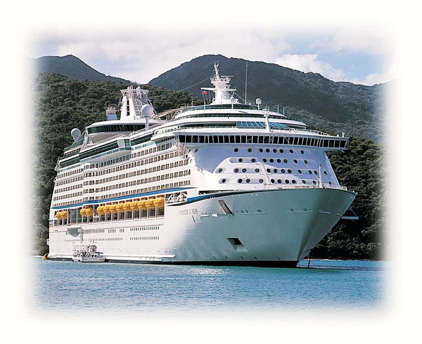
because it can be done in the air handling unit itself. Figure 2 shows an air handling unit and
how it supplies cool air to the cabins and how it removes the old air.
Figure 2.1.1
5Figure 2.1.2
The main principle of any HVAC-unit, such as
shown in figure 2.1.2, starts with the
evaporator. When the liquid it is still liquid,
but because of the temperature and the
space after the evaporator the liquid will
become a gas, to do this it will extract heat
from the space around the evaporator. As a
gas it will enter the compressor which will
bring the gas under high pressure. In the
condenser the high temperature will be
reduced and the gas will turn to a liquid. The
expansion valve regulates the amount of
liquid that goes into the evaporator. This way
the liquid will turn from 100% liquid in the
expansion valve to 100% gas immediately
after the evaporator.
2.2 High Pressure System vs. Low Pressure system
The main principle behind the high pressure system is that the air is compressed so that
more mass of air can be transported used less space. The air is delivered at a rate of 8 to 18
m/s. It is well fit for smaller compartments.
The main principal of the low pressure system is to bring great volumes of air into the
compartments. It will use much space but the desired conditions in the room can be
achieved quickly since the amount of air that is brought into the room is relatively big
compared to the air that already is in the area.
The advantages of the High Pressure system compared to the Low Pressure system:
The high pressure system uses less space in its construction which makes the installation
easier and cheaper. It is also easier to control the air of the rooms differently, this way
separate rooms can have different climates provided by the same installation.
The advantages of the Low Pressure system compared to the High Pressure system:
The low pressure system can handle far bigger areas than the high pressure system. It
produces less inconvenience by noise. Also the high pressure system consumes more energy
through the fan which has to compress the air.
62.3 Number of Pipes
This refers to the supply and return of chilled and/or heated water to the air-handling unit.
Up to 4 pipes can be used to do this. The 2 pipe solution uses 1 pipe for the supply of hot or
cold water and 1 pipe for the return of this water. This is cheap to implement and is fairly
simple to build. It does however have the disadvantage of not being able to supply hot and
cold water at the same time so it isn’t very flexible in its heating or cooling capabilities. The 3
pipe system uses 1 pipe for the supply of hot water, 1 pipe for the supply of cool water and 1
return pipe. The advantage of this is that it is more flexible than the 2 pipe system. It does
however need more equipment and you can’t reuse the return flow easily because it is a
mixture of the supplied air and the original air. Then there is the most expensive 4 pipe
option where there is a separate pipe for the supply and return for both the hot and cold
water. This is fairly expensive to purchase and maintain. It offers the highest amount of
flexibility because both hot and cold water are separately available at the air-handling unit.
Table 2.3
Costs (+ = cheap / Flexibility (+ = flexible /
- = expensive) - = not flexible)
2-pipes ++ -
3-pipes + +
4-pipes - ++
2.4 Centralised units
A centralised unit has all the mechanical equipment in one plant. The plant is connected to
the areas with ducts and pipes. Both the strength and weakness of the system is that all the
technical intensive equipment is kept together on bigger scale. The advantage of this is that
the fragile parts of the system are kept together far away from, for instance, public areas.
Another advantage is that all the noise is kept away from these public areas as well.
Disadvantages come with the size of the system, in the duct- and piping this will bring little
trouble, but the machinery is complicated and large scaled wherefore a well educated
operator is necessary.
72.5 Decentralised units
Every area has its own independent, smaller unit to handle the air. This keeps the units far
less complex and thus easy to work with. The individual areas can be differently handled to
the requests that fit the room or the users of the room. When one unit has a malfunction
only the room it is installed in is affected. Disadvantages are that the heating and cooling
capacity of the units are very limited. It takes very advanced systems to fit the change in
climate the unit will experience during a voyage, making these units the more expensive
versions in their branch. The systems are more fragile and since they are operating in the
area it self they will also be noisier.
2.6 Cruise ship HVAC
On cruise ships the Cabin areas are usually serviced by a High pressure Decentralized system
that is either completely self-sufficient or one that makes use of water circulation, because
of the easily replaceable parts and some other advantages (the cabins can control their air
individually, this way one can adjust the climate in his cabin to his own desire without
affecting, or being affected by the other cabins). In the large areas a low pressure system is
used for the reason that it transports a big volume of air. We will focus mainly on the cabin
systems seeing as this is one of the bigger parts in energy consumption of the complete air
conditioning system.
83. The HVAC Systems
3.1 Constant airflow with Reheating (CAV + Reheating)
This system delivers a constant volume of air and works by regulating the temperature of the
supplied air by reheating it from the base supply level to one that is wanted in the specific
area using reheating coils.
This is the simplest of the systems and it works well without a complicated automation
system. Reheating, Heating of the air sent to the cabins at a cabin level so called because
first you cool the air to a certain temperature at the air handling unit and then you reheat it
at the cabin, is separately arranged at the air handling unit for the different cabin zones and
it is based on the outside temperature and a regulating curve. The cabin device always
provides a constant air flow that is additionally reheated in the device when needed. Electric
reheating is regulated either with on/off principle or analogue. Reheating provides the
required cabin-specific temperature rise. It’s a simple system but it is very inefficient it is also
not very flexible in the temperature ranges it can provide. It makes up for this with its cost
and due to its simplicity it has few parts that can break resulting in a better reliability and a
small size because it does not need any cool water piping.
93.2 Variable Airflow (VAV)
This system uses air of a constant temperature and adjusts the volume of air that is supplied
to cope with the area’s needs in cooling. The more cooling needed the higher the volume of
air that needs to be admitted to attain the required cooling effect.
This system is based on the regulation of air flow and it works well without a complicated
automation system. Temperature regulation is zone specific in the air handling unit, which
does not allow major heat load variations between the different cabins in the zone. The air
flow in the cabin unit is regulated manually or using cabin automation. This system is equally
suitable for warm operational areas. A simple system but it is not very user friendly because
you can only set the temperature for an entire zone. It is however more efficient then the
CAV. It is a relatively cheap system with few parts and because it’s a decentralised system it
requires less space and is quite reliable.
103.3 Variable Airflow with reheating (VAV + Reheating)
This is an improved version of the air flow regulated cabin system. It is based on air flow
regulating and electric reheating. The extra heating makes this system very competitive for
ships in colder operational areas. The electric heating coil is usually integrated in the cabin
unit. Regulation can be manual or use a cabin thermostat. This system is much like the
normal VAV but it raises the comfort level by adding a heating unit in the cabin. This will take
a slight toll on the efficiency but this could be a price worth paying. Because of the extra
heating and cabin control unit it is slightly more expensive than the normal VAV.
113.4 Twin Duct
This system works by mixing hot and cold air. It’s rather inefficient because it needs to be on
constantly to keep a comfortable temperature. However this type of system lends itself to
the using of cooling water from the engine and then to mix it with the cold air.
This is a traditionally used system. Supply air is led into cabins through 2 ducts. One of them
is a cold air duct and the other is provided with a heating coil located in the air handling unit.
Cabin specific regulation is carried out by adjusting the mixing ratio of cold and warm air.
The system requires the space for twin ducting and also increases the ship’s weight. It is not
a very efficient system but it does offer a high level of comfort to the passengers. Because of
the extra ducting and control systems that need to be installed it is moderately expensive. It
has an good reliability because of relatively simple control systems.
123.5 Airflow regulated with water circulation (Smart Air)
The system is based on air flow regulation and cooling with water circulation. The accurate
regulating system provides good cabin temperature control. The system is excellent for ships
in warm operational areas. The cooling coil is integrated in the cabin unit. The temperature
regulation is usually done with the aid of sensors, cabin regulators and automation systems.
The system does not require insulated supply air ducts because cooling is arranged in the
cabin. The system however requires water circulation piping. It is an expensive system but it
does have a very high efficiency because of the water cooling which reduced the energy
required for cooling the air by a fair amount. But it is not capable of heating which can be a
problem. It has a fairly large size overall because of the extra piping that is required but
because the air ducts don’t need to be insulated some space is saved. Because of the extra
system cooling requires it has a larger chance of parts malfunctioning.
3.6 Air recirculation with reheating and water circulation (CFAF)
This system works my mixing old and fresh air and then reheating it to the required
temperature in the cabin with a reheating coil. It uses water cooling for use with the cold air
duct. This system could also use warm exhaust water to create a mixing system.
Fan coil includes a fan, reheating, cooling and a filter. The fan recirculates air through the
cabin unit so that a specified amount of fresh air is constantly mixed into the recirculated air.
13The minimum amount of fresh air is determined by the number of occupants of a cabin. The
conditions in the cabin can be regulated with the heating/cooling coil. Exhaust air is usually
extracted through the toilet. With its accurate regulating system, this system provides very
precise temperature control, and it is excellent for ships with warm as well as cold
operational areas. One of the benefits of this system is the small amount of fresh air needed,
which means a reduced number of air handling units. The cabin system needs a separate
cooling water piping and insulated supply air ducts. The fan located in the cabin will slightly
raise the noise level but this can be offset by proper duct insulation. The use of recirculated
air requires good filtering to maintain proper air quality. This is the most expensive system
but it also offers the best efficiency. Because of all the ducting and piping required it also a
very sizable system which is slightly offset by the reduction of the amount of air handling
units required. It offers maximum comfort in every climate. Yet it is still prone to failing parts
because of all the control systems that are required and the amount of parts that can break
down.
144. Comparison Table
The systems mentioned in chapter 3 are here compared to one another upon the following
aspects:
Environment: How environmentally friendly is the system?
Efficiency: How energy efficient is the system at cooling?
Purchasing cost: The costs of installing the system
Reliability: How much maintenance is required?
Size: How much space does the system require?
Comfort: How much user comfort does it offer?
System Environment Efficiency Purchasing Reliability Size Comfort
Cost
CAV + -- -- ++ ++ + -
Reheating
VAV - 0 + + ++ --
VAV + - - 0 + + +
Reheating
Twin Duct + - - + - ++
VAV + WC ++ + -- 0 -- +
CFAF + WC + ++ -- - - ++
( -- = Catastrophic , - = Bad , 0 = mediocre, + = Good, ++ = Excellent)
155.Future of HVAC
5.1 The environment
The biggest change here compared to the last years is the change of cooling liquid that is used to cool
the water because of the Montreal protocol. For the Montreal protocol see chapter 5.3. But of
course any progress made in efficiency directly effects the environmental impact because of less fuel
consumption resulting in less exhaust gases.
5.2 Efficiency
The biggest progress being made nowadays is using intelligent electronic control devices that
minimize the cooling and heating of rooms that are not being used and maximize the efficiency of
the entire HVAC system. This can result in up to 30% less power consumption. The HVAC systems are
mostly updated to provide better and more reliable cooling and heating and no great leaps in
efficiency are expected.
5.2.1 High Efficiency Air Conditioning
Air conditioners are rated on their efficiency using a measurement known as the Seasonal Energy
Efficiency Ratio (SEER). This measurement is the cooling output divided by the energy consumption
with climate and certain other variables factored in. The higher the SEER number, the more efficient
the unit, is the general rule. Older units might have a SEER as low as 7 or 8. For a long time, The
Department of Energy mandated a SEER of 10 as the minimum for all newly installed units. This
figure has recently been raised to 13, and is a topic for debate currently. Some units are capable of
SEER ratings as high as 17 or 18.
For a example see appendix 1
Window units use EER (Energy Efficient Ratio) rather than SEER, but the principle is basically the
same. The principle of “bigger is not necessarily better” applies to window units also. Humidity plays
such an important role in comfort, and is often more important than just mere temperature. Smaller
units tend to remove more moisture because they have longer runs. When a unit first starts it
actually blows a bit of moisture out of the unit. Once the cycle is running smoothly, the condensation
of moisture on the cooling cools begins. SEER is related to the Energy Efficiency Ratio (EER), which is
the ratio of output cooling in Watts/Hr and the input power in watts W at a given operating point and
also to the coefficient of performance (COP) commonly used in thermodynamics. Performance ratios
can be a unitless output over input ratio, never to exceed one, and it is also proper to state what kind
of energy is in the numerator and denominator. The COP of a heat pump is determined by dividing
the power output of the heat pump by the electrical power needed to run the heat pump, with both
powers measured using the same units, e.g. watts. The higher the COP, the more efficient the heat
pump. For example resistive heat has a COP = 1. The EER is the efficiency rating for the equipment at
a particular pair of external and internal temperatures.
1 BTU = (British Thermal Units)= 0.0002929 kW
1 Watt = 3,4121 BTU
1kW = 3414 BTU
165.2.2 Theoretical maximum
The SEER and EER of an air conditioner are limited by the laws of thermodynamics The refrigeration
process with the maximum possible efficiency is the Carnot cycle. The COP of an air conditioner using
the Carnot cycle is:
where TC is the indoor temperature and TH is the outdoor temperature. Both temperatures must be
measured using a thermodynamic temperature scale such as Kelvin.
where
ΔQcool is the amount of heat extracted from a cold reservoir at temperature Tcool,
ΔQhot is the amount of heat delivered to a hot reservoir at temperature Thot,
ΔA is the compressor's dissipated work.
All temperatures are absolute temperatures usually measured in kelvins (K).
For an indoor temperature of 299.81 K (26.7 ˚C) and an outdoor temperature of 308.15 K, (34.9 ˚C)
the above equation gives an COP of 36.0, or an EER of 123. This is about 10 times as efficient as a
typical home air conditioner available today.
The maximum EER decreases as the difference between the inside and outside air temperature
increases, and vice versa. In desert climates, where the temperature may be as high as 50˚C, the
maximum COP drops to 13.5, or an EER of 46 (assuming an outdoor temperature of as 50˚C and an
indoor temperature of 26.7˚C).
The maximum SEER can be calculated by averaging the maximum EER over the range of expected
temperatures for the season.
17The carnot-cycle is a theoretic thermo dynamical cycle whereby all the heat is supplied by the hottest
temperature, and is drained off by the lowest temperature.
Carnot says that the efficiency of the machine is not dependent on the type of fluid, rather it
depends on the maximum and minimum temperatures between which the heat engine cycle
operates.
The high temperature reservoir from where the heat is absorbed at high temperature is called as
source and low temperature reservoir, usually atmosphere, where the heat is rejected is called as
sink. Thus the efficiency of Carnot cycle depends on the temperatures of the source and sink,
measured in Kelvin i.e. the absolute temperature.
185.2.3 Solar Air Conditioning
Environmental concerns are a very important factor in a number of areas and air conditioning is one
of them. The wide spread use of air conditioning has created ever increasing electrical energy
demands, and the power generating capacity is struggling to keep up with this demand. During
demand peaks created by hot spells, there have been power outages and brown-outs in the past.
One of the ideas that has been developed to cope with this problem is the use of the sun as a power
source. This seems a logical concept since the sun creates the problem by creating heat. Wouldn't it
be great if the sun could also provide the solution.
The method used is based on the thermo-chemical process known as sorption. Sorption takes two
forms. When a liquid or gas is attached to a porous, solid material it is called adsorption. When the
liquid or gas is taken in by liquid or a solid, it is called absorption. The European technology involves
the use of a sorbant, usually silica gel. The silica gel is heated by the sun and is dehumidified. When
water vapor or steam is added to the dehumidified gel, adsorption takes place and heat is released.
Basically, when heated ambient air is drawn through the system in what is called a heat reclamation
rotor, the heat is drawn out of the air, cooling it. The cooled air is recycled back into the ship. The
major drawback to this system is the large size of the units, and of the area that must be exposed to
the sun.
Solar energy for home use is an emerging technology also. However, the idea here is to use the
energy to power existing air conditioning units rather than replacing them with new technology.
Photovoltaic cells mounted on the roof converts solar energy into AC power that can be used to
power the air conditioner. In most cases, the amount of power is not sufficient to run the unit, but
can supplement the regular electrical supply. The major advantage here is that when the electrical
demand is the highest, which would be during the peak daylight hours, the sun will be bearing down
most directly on the PV cells.
There is a surge in power consumption during start up of an air conditioner unit. Solar photovoltaic
cells can be used to keep the unit running at a very low speed during times it would normally be shut
down. This can further reduce the regular electrical use by eliminating many of the starts and stops
of the cycle. Solar energy is an emerging technology in a world that is seeking alternative sources of
power. Hopefully, in the future, the sun, which creates the heat and humidity that we seek to
19eliminate with air conditioning, will provide the solution to our continued comfort.
205.3 The Montreal Protocol
The Montreal Protocol on Substances That Deplete the Ozone Layer (a protocol to the Vienna
Convention for the Protection of the Ozone Layer) is an international treaty designed to protect the
ozone layer by phasing out the production of a number of substances believed to be responsible for
ozone depletion. The treaty was opened for signature on September 16, 1987, and entered into force
on January 1, 1989, followed by a first meeting in Helsinki, May 1989. Since then, it has undergone
seven revisions, in 1990 (London), 1991 (Nairobi), 1992 (Copenhagen), 1993 (Bangkok), 1995
(Vienna), 1997 (Montreal), and 1999 (Beijing). It is believed that if the international agreement is
adhered to, the ozone layer is expected to recover by 2050. Due to its widespread adoption and
implementation it has been hailed as an example of exceptional international co-operation with Kofi
Annan quoted as saying that "perhaps the single most successful international agreement to date has
been the Montreal Protocol".
As per EPA (Environmental Protection Agency), the timeline is as follows:
January 1, 2010: By this date there would be complete ban on the production and import of R22 and
R142b. However, there is exception for the on-going servicing needs of the existing plants and
equipment.
January 1, 2015: By this date there would be ban on the sale and use of R22. There is exception for
certain cases, including the serving needs of the existing refrigeration and air conditioning
equipment.
January 1, 2020: By this date there would complete ban on the production and import of R22
refrigerant. The gas would not be available even for servicing of the existing plants.
215.4 Cooling Liquids
Freon is a chlorofluorocarbon, which is an organic compound that contains carbon, chlorine, and
fluorine. Freon was developed as a safer alternative for ammonium(NH3), Chloromethane (CH3Cl),
and Sulfur dioxide (SO2), that was used in cooling systems before Freon was discovered. Freon is
extremely safe, inflammable and not poison.
Connecting environmental impact the Freon’s are classified in this groups:
CFC’s : Chlorofluorocarbons, without H-atoms. These substances have a big impact on the ozone
layer, and are illegal to sell.
HFC’s : hydrochlorofluorocarbons, without chloride, but with hydrogen atoms. An example of this is
134a.
HCFC’s: Hydrochlorofluorocarbons, they are also bad for the ozon layer, but less than CFC’s. An
example of this is Freon 22
The most common cooling liquids are R134a; R407C; R410a on new vessels.
5.4.1 Refrigerant R410A
R-410A, sold under the trademarked names Puron, Genetron R410A, and AZ-20, is a near-azeotropic
mixture of difluoromethane (CH2F2, called R-32) and pentafluoroethane (C2HF5, called R-125), which
is used as a refrigerant in HVAC air conditioning applications.
Unlike many haloalkane refrigerants it does not contribute to ozone depletion, and is therefore
becoming more widely used as ozone-depleting refrigerants like R-22 are phased out. However, it
has a high global warming potential of 1725 (1725 times the effect of carbon dioxide) similar to that
of R-22. R-410A is also the preferred refrigerant for use in residential and commercial air
conditioners in Japan and Europe, replacing R-22.
R-410A is incompatible with R-22 refrigerant. R-410A is used at much higher operating pressures
than R-22 and other newer refrigerants.
New equipment that uses R-410A will require service personnel to acquire different tools and
equipment, safety standards and fundamentals when installing, replacing older split A/C systems,
and repairing systems in the field.
HVAC service persons need to understand the safe handling, proper charging, operating
characteristics, proper applications, and general use of R-410A refrigerant.
R-410A should only be used in equipment specifically designed and constructed for higher pressure
refrigerants. R-410A operates at considerably higher pressures and requires the use of special tanks,
gauges and recovery equipment.
R-410A requires training of installation and service personnel in the proper and safe handling of R-
410A.
22R-410A needs service personnel to understand why all refrigerant flow controls, valves and driers
have changed and must be properly applied with newly designed and built compressors.
Many equipment manufacturers are well aware of the concerns and safety issues of working with R-
410A and other HFC refrigerants and are requiring installation and service professionals who
purchase their R-410A systems to be R-410A Certified.
In order to prepare air conditioning professionals for the challenges presented by R410A, some of the
major organizations in the HVACR created the AC&R Safety Coalition.
235.4.2 Physical properties R410A
Property Value
Formula 50% CH2F2/50% CHF2CF3
Molecular Weight (Da) 72.6
Melting point (°C) -155
Boiling point (°C) -48.5
Liquid density (30°C), kg/m3 1040
Vapour density (30°C), air=1.0 3.0
Vapor pressure at 21.1°C
1.383
(MPa)
Critical temperature (°C) 72.8
Critical pressure, MPa 4.86
Gas heat capacity @ 1 atm,
8.8
30°C (kJ/(kg·°C))
Liquid heat capacity @ 1 atm,
1.8
30°C, (kJ/(kg·°C))
For other refrigerants see appendix 2.
246. Recommendations/Conclusion
We will start by shortly summarising the information we have found concerning our research
questions this will be followed by a general conclusion.
How does air-conditioning work on cruise ships?
Generally on Cruise ships Air conditioning will be provided by Decentralised Systems,
Delivering Air conditioning to a group of cabins or areas.
What types of systems are available for air-conditioning?
Constant airflow with Reheating
A cheap system with little flexibility in provided temperature range. This system is fairly reliable but
does not provide a lot of comfort to passengers.
Variable Airflow
A cheap system, this provides a modicum of control over the temperature . It’s fairly reliable and
provides better Air conditioning then the constant airflow system. This is not suitable for cold
climates
Variable Airflow with reheating
A reasonably costly system. It provides good conditioning but is not very efficient in achieving this. it
can serve each individuals passengers climate while not being overly expensive in installation costs.
Airflow regulated with water circulation
An expensive system. A high efficiency is achieved by using water circulation. It has high installation
costs but good temperature control.
Air recirculation with reheating and water circulation
The most efficient and best system in our analysis. It delivers the best efficiency and air conditioning
but this comes at a cost. Due to the amount of working parts more maintenance can be required
Twin Duct
A costly system that requires room for the installation. It provides good passenger comfort but isn’t
very efficient.
What are the differences between the air-conditioning systems?
The differences are shown in the table in chapter 4, The differences are mainly in the efficiency of
the system and installation cost and the temperature range they can operate.
What differences are there regarding environmental impact?
If all the systems use the latest Freon substitutes, there is little environmental impact from those.
How ever the more efficient a system is the less power needs to be generated to power the system
25and so the fuel consumption of a ship can be reduced. Which results in less exhaust emissions which
reduces the environmental impact.
What differences are there regarding efficiency?
There are fairly big differences in efficiency that can be gotten through using centralized cooling
system. A good automatic control system to regulate the entire air conditioning system can also
reduce energy consumption by up to 25%.
What differences are there regarding the purchasing costs?
There are big diffrences mainly because some systems are fairly easy to install and require few
complicated components while there also systems that require elaborate piping and electronics to be
installed to get the most out of the system
How dependable are the systems?
Overall the systems are quite dependable in that most can operate on their own . Still the more
elaborate systems can cause trouble because there are more parts that can malfunction and cause a
problem.
How suitable are the systems for use on cruise ships?
The systems that are available work relatively well although some are only suitable for use in warm
locations. The systems are made so that they are resistant to the high salinity in the air and the
changes in climates that a normal system does not have to cope with.
In what direction are improvements on air-conditioning systems
currently sought by air-conditioning suppliers?
Most improvements are currently being made in the field of automatic control of the climate system
to reduce unnecessary air conditioning and supplying exactly the right amount of cooling that is
required.
How is/can waste energy from the main-engines (be) used for air-
conditioning systems?
When sailing in cold climates the waste energy from the engines could be used to heat the air to a
correct temperature without using an electric reheating coil this could increase efficiency at the cost
of installing lots of insulated piping.
General Conclusion
There are several main factors that need to be looked at when choosing an Air conditioning
System. These are the climate of the places the ship is expected to sail, the size of your
vessel, the amount of comfort required by the users of the system and the projected lifespan
of the ship. Generally it can be said that the air conditioning options with the highest
purchasing costs are environmentally friendlier because of their higher efficiency. But overall
the initial costs will be won back quite quickly because of the reduced fuel consumption.
Further research could focus more on the HVAC control systems, or an in depth look at the
future of Cooling liquids.
267. References
Wikipedia.com
Hvac control system design by I. Levenhagen
2008 HVAC Systems and Equipment (I-P Edition) by ashrea
www.koja.fi
Product information from various supplier websites.
www.brichthub.com
http://www.absoluteastronomy.com
http://www.airconditioningrepaircompanies.com
Boek: Warmteleer voor technici, ir. A.J.M. van Kimmenaeda
Hulpwerktuigen 1 en 2, W. Smit
Appendix 1
SEER
27The SEER rating is the Btu of cooling output during a typical cooling-season divided by the total
electric energy input in watt-hours during the same period.
For example, consider a 5000 BTU/h air-conditioning unit, with a SEER of 10, operating for a total of
1000 hours during an annual cooling season (e.g., 8 hours per day for 125 days).
The annual total cooling output would be:
5000 BTU/h * 8 h/day * 125 days = 5,000,000 BTU
With a SEER of 10, the annual electrical energy usage would be about:
5,000,000 BTU / 10 BTU/W·h = 500,000 W·h
The average power usage may also be calculated more simply by:
Average power = (BTU/h) / (SEER, BTU/W·h) = 5000 / 10 = 500 W
If your electricity cost is 20¢/kW·h, then your operating cost is:
0.5 kW * 20¢/kW·h = 10¢/h
1 BTU = (British Thermal Units)= 0.0002929 kW
1 Watt = 3,4121 BTU
1kW = 3414 BTU
EER
EER (Btu/(W*hr)) is converted to COP (Btu/Btu by dividing by 3.413 Btu/(Hr*W).
The SEER is calculated at a part loaded standardized ARI test. (Defined on/off cycle) This more closely
represents the performance from equipment cycling, instead of the steady state conditions under
which the EER is measured.
Typical EER for residential central cooling units = 0.875 X SEER
SEER is always a higher value than EER for the same equipment.
A SEER of 13 is approximately equivalent to a COP of 3.43, which means that 3.43 units of heat
energy are removed from indoors per unit of work energy used to run the heat pump.
Properly maintaining the system will also result in increased efficiency. Routine changing of filters is
one of the most important maintenance requirements. The wide spread use of air conditioning has
created a large strain on electrical power demand especially during heat waves. Power generation is
struggling to keep up with demand and brown-outs have become frequent during periods of high
demand. Air conditioning efficiency takes place on an individual level, but the air conditioning
industry is working to improve efficiency with improved models and the development of new
technology as well.
28Appendix 2
Other refrigerants:
R-401A is a HCFC zeotropic blend of R-32, R-152a, and R-124. It is designed as a replacement for R-
12.
R-404A is a HCFC "nearly azeotropic" blend of 52 wt.% R-143a, 44 wt.% R-125, and 4 wt.% R-134a. It
is designed as a replacement of R-22 and R-502 CFC. Its boiling point at normal pressure is -46.5 °C,
its liquid density is 0.485 g/cm3.
R-406A is a zeotropic blend of 55 wt.% R-22, 4 wt.% R-600a, and 41 wt.% R-142b.
R-407A is a HCFC zeotropic blend of 20 wt.% R-32, 40 wt.% R-125, and 40 wt.% R-134a.
R-407C is a zeotropic hydrofluorocarbon blend of R-32, R-125, and R-134a. The R-32 serves to
provide the heat capacity, R-125 decreases flammability, R-134a reduces pressure.
R-408A is a zeotropic HCFC blend of R-22, R-125, and R-143a. It is a substitute for R-502. Its boiling
point is -44.4 °C.
R-409A is a zeotropic HCFC blend of R-22, R-124, and R-142b. Its boiling point is -35.3 °C. Its critical
temperatiure is 109.4 °C.
R-410A is a near-azeotropic blend of R-32 and R-125. The US Environmental Protection Agency
recognizes it as an acceptable substitute for R-22 in household and light commercial air conditioning
systems. It appears to have gained widespread market acceptance under several trade names.
R-500 is an azeotropic blend of 73.8 wt.% R-12 and 26.2 wt.% of R-152a.
R-502 is an azeotropic blend of R-22 and R-115.
Year Chemical Quantity
1994 141b 0% (other than foam)
291996 All HCFCs CAP = HCFCs + 2.8% CFCs in 1989
2003 141b 0%
2004 All HCFCs 65% of CAP
2010 All HCFCs 35% of CAP
142b 0% of new products
22 0% of new products
142b, 22 Freeze at 2009 levels
2015 All HCFCs 10% of CAP
All HCFCs Freeze at 2014 level
2020 All HCFCs 0.5% of CAP
22 0%
142b 0%
123 0% of new products
124 0% of new products
2030 All HCFCs 0% of CAP
30You can also read