Real-Time Data Monitor User's Guide
←
→
Page content transcription
If your browser does not render page correctly, please read the page content below
Real-Time Data Monitor
                                             User’s Guide

© 2008 Microchip Technology Inc.                      DS70567A
Note the following details of the code protection feature on Microchip devices:
•    Microchip products meet the specification contained in their particular Microchip Data Sheet.

•    Microchip believes that its family of products is one of the most secure families of its kind on the market today, when used in the
     intended manner and under normal conditions.

•    There are dishonest and possibly illegal methods used to breach the code protection feature. All of these methods, to our
     knowledge, require using the Microchip products in a manner outside the operating specifications contained in Microchip’s Data
     Sheets. Most likely, the person doing so is engaged in theft of intellectual property.

•    Microchip is willing to work with the customer who is concerned about the integrity of their code.

•    Neither Microchip nor any other semiconductor manufacturer can guarantee the security of their code. Code protection does not
     mean that we are guaranteeing the product as “unbreakable.”

Code protection is constantly evolving. We at Microchip are committed to continuously improving the code protection features of our
products. Attempts to break Microchip’s code protection feature may be a violation of the Digital Millennium Copyright Act. If such acts
allow unauthorized access to your software or other copyrighted work, you may have a right to sue for relief under that Act.

Information contained in this publication regarding device               Trademarks
applications and the like is provided only for your convenience          The Microchip name and logo, the Microchip logo, Accuron,
and may be superseded by updates. It is your responsibility to
                                                                         dsPIC, KEELOQ, KEELOQ logo, MPLAB, PIC, PICmicro,
ensure that your application meets with your specifications.
                                                                         PICSTART, rfPIC, SmartShunt and UNI/O are registered
MICROCHIP MAKES NO REPRESENTATIONS OR                                    trademarks of Microchip Technology Incorporated in the
WARRANTIES OF ANY KIND WHETHER EXPRESS OR
                                                                         U.S.A. and other countries.
IMPLIED, WRITTEN OR ORAL, STATUTORY OR
OTHERWISE, RELATED TO THE INFORMATION,                                   FilterLab, Linear Active Thermistor, MXDEV, MXLAB,
INCLUDING BUT NOT LIMITED TO ITS CONDITION,                              SEEVAL, SmartSensor and The Embedded Control Solutions
QUALITY, PERFORMANCE, MERCHANTABILITY OR                                 Company are registered trademarks of Microchip Technology
FITNESS FOR PURPOSE. Microchip disclaims all liability                   Incorporated in the U.S.A.
arising from this information and its use. Use of Microchip              Analog-for-the-Digital Age, Application Maestro, CodeGuard,
devices in life support and/or safety applications is entirely at        dsPICDEM, dsPICDEM.net, dsPICworks, dsSPEAK, ECAN,
the buyer’s risk, and the buyer agrees to defend, indemnify and          ECONOMONITOR, FanSense, In-Circuit Serial
hold harmless Microchip from any and all damages, claims,                Programming, ICSP, ICEPIC, Mindi, MiWi, MPASM, MPLAB
suits, or expenses resulting from such use. No licenses are              Certified logo, MPLIB, MPLINK, mTouch, PICkit, PICDEM,
conveyed, implicitly or otherwise, under any Microchip                   PICDEM.net, PICtail, PIC32 logo, PowerCal, PowerInfo,
intellectual property rights.                                            PowerMate, PowerTool, REAL ICE, rfLAB, Select Mode, Total
                                                                         Endurance, WiperLock and ZENA are trademarks of
                                                                         Microchip Technology Incorporated in the U.S.A. and other
                                                                         countries.
                                                                         SQTP is a service mark of Microchip Technology Incorporated
                                                                         in the U.S.A.
                                                                         All other trademarks mentioned herein are property of their
                                                                         respective companies.
                                                                         © 2008, Microchip Technology Incorporated, Printed in the
                                                                         U.S.A., All Rights Reserved.
                                                                              Printed on recycled paper.

                                                                         Microchip received ISO/TS-16949:2002 certification for its worldwide
                                                                         headquarters, design and wafer fabrication facilities in Chandler and
                                                                         Tempe, Arizona; Gresham, Oregon and design centers in California
                                                                         and India. The Company’s quality system processes and procedures
                                                                         are for its PIC® MCUs and dsPIC® DSCs, KEELOQ® code hopping
                                                                         devices, Serial EEPROMs, microperipherals, nonvolatile memory and
                                                                         analog products. In addition, Microchip’s quality system for the design
                                                                         and manufacture of development systems is ISO 9001:2000 certified.

DS70567A-page ii                                                                                        © 2008 Microchip Technology Inc.
REAL-TIME DATA MONITOR
                                                                              USER’S GUIDE

                                                 Table of Contents
Preface ........................................................................................................................... 1
Chapter 1. Introduction
                    1.1 Overview ........................................................................................................ 7
                    1.2 Features ......................................................................................................... 8
                    1.3 System Requirements .................................................................................... 8
Chapter 2. Getting Started
                    2.1 Running the Real-Time Data Monitor Code Example CE155 ........................ 9
                    2.2 Adding the Real-Time Data Monitor to an Application ................................. 18
                    2.3 Application Tips and Hints ............................................................................ 25
Chapter 3. Application Programming Interface (API)
                    3.1 API Functions and Constants ....................................................................... 27
Chapter 4. Protocol
                    4.1 The Protocol Model ...................................................................................... 33
                    4.2 Commands ................................................................................................... 34
                    4.3 ERROR Code ............................................................................................... 37
                    4.4 Files .............................................................................................................. 39
Chapter 5. DMCI Operating Modes
                    5.1 RTDM Mode ................................................................................................. 41
                    5.2 Data Capture Mode ...................................................................................... 42
                    5.3 Combine Mode ............................................................................................. 43
Index ............................................................................................................................. 45
Worldwide Sales and Service .................................................................................... 46

© 2008 Microchip Technology Inc.                                                                                          DS70567A-page iii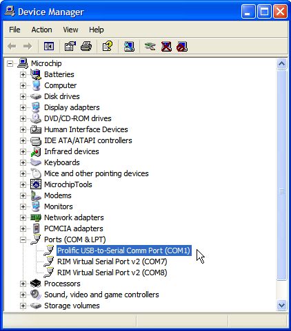
Real-Time Data Monitor User’s Guide
NOTES:

DS70567A-page iv                      © 2008 Microchip Technology Inc.
REAL-TIME DATA MONITOR
                                                                 USER’S GUIDE

                                                 Preface

                                     NOTICE TO CUSTOMERS
   All documentation becomes dated, and this manual is no exception. Microchip tools and
   documentation are constantly evolving to meet customer needs, so some actual dialogs
   and/or tool descriptions may differ from those in this document. Please refer to our web site
   (www.microchip.com) to obtain the latest documentation available.
   Documents are identified with a “DS” number. This number is located on the bottom of each
   page, in front of the page number. The numbering convention for the DS number is
   “DSXXXXXA”, where “XXXXX” is the document number and “A” is the revision level of the
   document.
   For the most up-to-date information on development tools, see the MPLAB® IDE on-line help.
   Select the Help menu, and then Topics to open a list of available on-line help files.

INTRODUCTION
                       This chapter contains general information that will be useful to know before using the
                       Real-Time Data Monitor (RTDM). Items discussed in this chapter include:
                       •   Document Layout
                       •   Conventions Used in this Guide
                       •   Warranty Registration
                       •   Recommended Reading
                       •   The Microchip Web Site
                       •   Development Systems Customer Change Notification Service
                       •   Customer Support
                       •   Document Revision History

DOCUMENT LAYOUT
                       This user’s guide describes how to use the Real-Time Data Monitor. The document is
                       organized as follows:
                       • Chapter 1. “Introduction” – This chapter introduces the real-time data
                         monitoring software developed for the MPLAB® Data Monitor and Control
                         Interface (DMCI) integrated on the MPLAB IDE 8.10 or higher. It also outlines
                         requirements for a host PC.
                       • Chapter 2. “Getting Started” – This chapter describes how to run the RTDM
                         code example, CE155, and how to add RTDM code to your application code.
                       • Chapter 3. “Application Programming Interface (API)” – This chapter outlines
                         how the API functions provided in the Real-Time Data Monitor, which can be
                         included in your application software via the Application Programming Interface.

© 2008 Microchip Technology Inc.                                                              DS70567A-page 1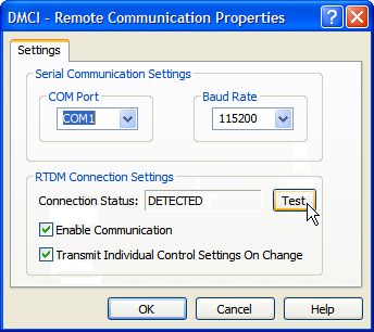
Real-Time Data Monitor User’s Guide

                  • Chapter 4. “Protocol” – This chapter describes the RTDM protocol specification,
                    which is used to debug dsPIC® DSC devices and PIC24H embedded applications
                    at run-time.
                  • Chapter 5. “DMCI Operating Modes” – This chapter outlines the different
                    MPLAB DMCI operating modes used for debugging applications in a real time
                    fashion.

DS70567A-page 2                                                           © 2008 Microchip Technology Inc.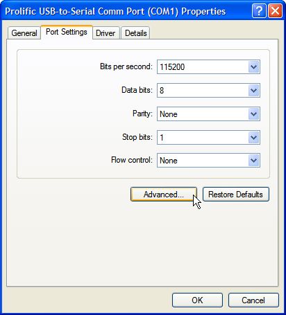
Preface

CONVENTIONS USED IN THIS GUIDE
                       This manual uses the following documentation conventions:

                       DOCUMENTATION CONVENTIONS
                                   Description                  Represents                          Examples
                        Arial font:
                        Italic characters              Referenced books                    MPLAB® IDE User’s Guide
                                                       Emphasized text                     ...is the only compiler...
                        Initial caps                   A window                            the Output window
                                                       A dialog                            the Settings dialog
                                                       A menu selection                    select Enable Programmer
                        Quotes                         A field name in a window or         “Save project before build”
                                                       dialog
                        Underlined, italic text with   A menu path                         File>Save
                        right angle bracket
                        Bold characters                A dialog button                     Click OK
                                                       A tab                               Click the Power tab
                        N‘Rnnnn                        A number in verilog format,         4‘b0010, 2‘hF1
                                                       where N is the total number of
                                                       digits, R is the radix and n is a
                                                       digit.
                        Text in angle brackets < >     A key on the keyboard               Press ,
                        Courier New font:
                        Plain Courier New              Sample source code                  #define START
                                                       Filenames                           autoexec.bat
                                                       File paths                          c:\mcc18\h
                                                       Keywords                            _asm, _endasm, static
                                                       Command-line options                -Opa+, -Opa-
                                                       Bit values                          0, 1
                                                       Constants                           0xFF, ‘A’
                        Italic Courier New             A variable argument                 file.o, where file can be
                                                                                           any valid filename
                        Square brackets [ ]            Optional arguments                  mcc18 [options] file
                                                                                           [options]
                        Curly brackets and pipe        Choice of mutually exclusive        errorlevel {0|1}
                        character: { | }               arguments; an OR selection
                        Ellipses...                    Replaces repeated text              var_name [,
                                                                                           var_name...]
                                                       Represents code supplied by         void main (void)
                                                       user                                { ...
                                                                                           }

WARRANTY REGISTRATION
                       Please complete the enclosed Warranty Registration Card and mail it promptly.
                       Sending in the Warranty Registration Card entitles users to receive new product
                       updates. Interim software releases are available at the Microchip web site.

© 2008 Microchip Technology Inc.                                                                         DS70567A-page 3
Real-Time Data Monitor User’s Guide

RECOMMENDED READING
                  This user’s guide describes how to use the Real-Time Data Monitor. Other useful
                  documents include:

                  dsPIC30F Family Reference Manual (DS70046)
                  Refer to this document for detailed information on dsPIC30F device operation. This
                  reference manual explains the operation of the dsPIC30F DSC family architecture and
                  peripheral modules but does not cover the specifics of each device. Refer to the
                  appropriate device data sheet for device-specific information.

                  dsPIC33F Family Reference Manual Sections
                  Refer to these documents for detailed information on dsPIC33F device operation.
                  These reference manual sections explain the operation of the dsPIC33F MCU family
                  architecture and peripheral modules, but do not cover the specifics of each device.
                  Refer to the appropriate device data sheet for device-specific information.

                  dsPIC30F/dsPIC33F Programmer’s Reference Manual (DS70157)
                  This manual is a software developer’s reference for the dsPIC30F and dsPIC33F 16-bit
                  MCU families of devices. It describes the instruction set in detail and also provides
                  general information to assist in developing software for the dsPIC30F and dsPIC33F
                  MCU families.

                  MPLAB® ASM30, MPLAB® LINK30 and Utilities User’s Guide (DS51317)
                  This document helps you use Microchip Technology’s language tools for dsPIC DSC
                  devices based on GNU technology. The language tools discussed are:
                  • MPLAB ASM30 Assembler
                  • MPLAB LINK30 Linker
                  • MPLAB LIB30 Archiver/Librarian
                  • Other Utilities

                  MPLAB® C30 C Compiler User’s Guide (DS51284)
                  This document helps you use Microchip’s MPLAB C30 C compiler for dsPIC DSC
                  devices to develop your application. MPLAB C30 is a GNU-based language tool, based
                  on source code from the Free Software Foundation (FSF). For more information about
                  the FSF, see www.fsf.org.
                  Other GNU language tools available from Microchip are:
                  • MPLAB ASM30 Assembler
                  • MPLAB LINK30 Linker
                  • MPLAB LIB30 Librarian/Archiver

                  MPLAB® IDE Simulator, Editor User’s Guide (DS51025)
                  Refer to this document for more information pertaining to the installation and
                  implementation of the MPLAB Integrated Development Environment (IDE) software.
                  To obtain any of these documents, contact the nearest Microchip sales location (see
                  back page) or visit the Microchip web site at: www.microchip.com.

                  Microsoft® Windows® Manuals
                  This user’s guide assumes that you are familiar with the Microsoft Windows operating
                  system. Many excellent references exist for this software program and should be
                  referenced for general operation of Windows.

DS70567A-page 4                                                             © 2008 Microchip Technology Inc.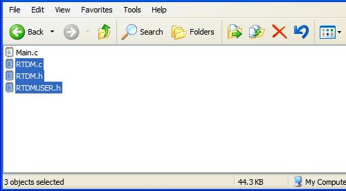
Preface

THE MICROCHIP WEB SITE
                       Microchip provides online support via our web site at www.microchip.com. This web
                       site is used as a means to make files and information easily available to customers.
                       Accessible by using your favorite Internet browser, the web site contains the following
                       information:
                       • Product Support – Data sheets and errata, application notes and sample
                         programs, design resources, user’s guides and hardware support documents,
                         latest software releases and archived software
                       • General Technical Support – Frequently Asked Questions (FAQs), technical
                         support requests, online discussion groups, Microchip consultant program
                         member listing
                       • Business of Microchip – Product selector and ordering guides, latest Microchip
                         press releases, listing of seminars and events, listings of Microchip sales offices,
                         distributors and factory representatives

DEVELOPMENT SYSTEMS CUSTOMER CHANGE NOTIFICATION SERVICE
                       Microchip’s customer notification service helps keep customers current on Microchip
                       products. Subscribers will receive e-mail notification whenever there are changes,
                       updates, revisions or errata related to a specified product family or development tool of
                       interest.
                       To register, access the Microchip web site at www.microchip.com, click on Customer
                       Change Notification and follow the registration instructions.
                       The Development Systems product group categories are:
                       • Compilers – The latest information on Microchip C compilers and other language
                         tools. These include the MPLAB C18 and MPLAB C30 C compilers; MPASM™
                         and MPLAB ASM30 assemblers; MPLINK™ and MPLAB LINK30 object linkers;
                         and MPLIB™ and MPLAB LIB30 object librarians.
                       • Emulators – The latest information on Microchip in-circuit emulators. This
                         includes the MPLAB ICE 2000, MPLAB ICE 4000 and MPLAB REAL ICE.
                       • In-Circuit Debuggers – The latest information on the Microchip in-circuit
                         debugger, MPLAB ICD 2.
                       • MPLAB® IDE – The latest information on Microchip MPLAB IDE, the Windows®
                         Integrated Development Environment for development system tools. This list is
                         focused on the MPLAB IDE, MPLAB SIM simulator, MPLAB IDE Project Manager
                         and general editing and debugging features.
                       • Programmers – The latest information on Microchip programmers. These include
                         the MPLAB PM3 and PRO MATE® II device programmers and the PICSTART®
                         Plus and PICkit™ 1 development programmers.

CUSTOMER SUPPORT
                       Users of Microchip products can receive assistance through several channels:
                       •   Distributor or Representative
                       •   Local Sales Office
                       •   Field Application Engineer (FAE)
                       •   Technical Support
                       •   Development Systems Information Line
                       Customers should contact their distributor, representative or Field Application Engineer
                       (FAE) for support. Local sales offices are also available to help customers. A listing of
                       sales offices and locations is included in the back of this document.
                       Technical support is available through the web site at: http://support.microchip.com

© 2008 Microchip Technology Inc.                                                                DS70567A-page 5
Real-Time Data Monitor User’s Guide
DOCUMENT REVISION HISTORY
Revision A (December 2008)
Initial release of this document.
DS70567A-page 6 © 2008 Microchip Technology Inc.REAL-TIME DATA MONITOR
USER’S GUIDE
Chapter 1. Introduction
This chapter introduces the Real-Time Data Monitoring (RTDM) software developed for
the MPLAB Data Monitor and Control Interface (DMCI), which is integrated on MPLAB
IDE 8.10 or higher. These DMCI features address the need for monitoring and
modifying data in a real-time fashion.
This user’s guide provides information you can use to incorporate the RTDM into your
embedded solution. Topics covered include:
• Overview
• Features
• System Requirements
1.1 OVERVIEW
Most existing embedded applications demand more complex and sophisticated
debugging tools, providing methods to reduce the development cycle, and therefore,
the time-to-market.
The MPLAB DMCI provides dynamic input control of application variables in MPLAB
IDE projects. Application-generated data can be viewed graphically using any one of
four dynamically-assignable graph windows.
Applications such as motor control and power conversion require high-speed data
monitoring from MPLAB DMCI. Achieving such tasks with the existing debugging tools
and the on-chip debugging module, requires the use of an additional communication
link between a host PC and a target device.
RTDM, along with MPLAB DMCI (MPLAB 8.10 or higher), creates an alternative link
between a host PC and a target device for debugging applications in real-time.
Using these tools for getting data in and out of the target device allows developers to
run their applications, while providing the ability to tune the variables and immediately
see the effect without halting the application. Figure 1-1 provides an example
application.
FIGURE 1-1: APPLICATION EXAMPLE
MPLAB® DMCI RTDM software running in
users’s application code
USB or RS-232
© 2008 Microchip Technology Inc. DS70567A-page 7Real-Time Data Monitor User’s Guide
1.2 FEATURES
RTDM has the following features:
• Runs under Debug mode or user’s application
• Fully compatible with MPLAB DMCI
• Provides dynamic access to control and monitor software variables without halting
program execution
• No recompiling is required between debug sessions
• Ability to control or view any global variable defined by the target application code
• Provides an alternative link to read/write data from/to the target device
• Uses the RS-232 standard protocol as the primary communication link between
the host PC and target device
• Maximum baud rate: 460800 bps
• Configurable to use the UART1 or UART2 modules on the target device
• Supported by all dsPIC30F, dsPIC33F and PIC24H devices
1.3 SYSTEM REQUIREMENTS
The RTDM code requires the following resources on the target device:
• One UART module
• Flash memory used:
- 2 Kbytes of Flash if the dsPIC Peripheral Library is used, or
- 600 bytes if the UART driver is configured using hardware-dependent code
• RAM used: 48 bytes plus buffered data
• 1 MIPS
DS70567A-page 8 © 2008 Microchip Technology Inc.REAL-TIME DATA MONITOR
USER’S GUIDE
Chapter 2. Getting Started
This chapter describes how to run the RTDM code example, CE155, and how to add
RTDM code to your application code. Topics covered include:
• Running the Real-Time Data Monitor Code Example CE155
• Adding the Real-Time Data Monitor to an Application
• Application Tips and Hints
2.1 RUNNING THE REAL-TIME DATA MONITOR CODE EXAMPLE CE155
This code example shows how to use RTDM to create an alternative link between a
host PC and a target device for debugging applications in real-time using MPLAB DMCI
(MPLAB 8.10 or higher). You can download the code example, CE155, from the
Microchip web site (www.microchip.com/codeexamples). This code example runs on
the dsPIC33FJ256GP710 and utilizes the Explorer 16 Development Board
(DM240001).
1. Open the RTDM code example by double-clicking the file,
RTDM Code Example.mcw, as shown in Figure 2-1.
FIGURE 2-1: OPENING THE RTDM CODE EXAMPLE MPLAB® IDE WORK
SPACE
2. Once the MPLAB workbench is open, compile the project by selecting
Project>Build All, as shown in Figure 2-2.
Note: This step requires the use of the MPLAB C Compiler version 3.10 or higher.
© 2008 Microchip Technology Inc. DS70567A-page 9Real-Time Data Monitor User’s Guide
FIGURE 2-2: COMPILING THE PROJECT
3. Select the desired programmer to program the target device. For example, to
choose MPLAB® REAL ICE™, select Programmer>Select Programmer>REAL
ICE, as shown in Figure 2-3. Then hit the program button or go to
Programmer>program. This action will download the program to the target
device.
FIGURE 2-3: SELECTING THE PROGRAMMER
4. Connect the host PC to the target device. If your PC has a serial port, connect
the PC port to the DB9 connector P1 (Explorer 16 Development Board), and then
identify your COM port. If your PC does not have a serial port, you will need a
USB-to-Serial adapter. Please install the USB-to-Serial adaptor USB driver
before proceeding. The following steps describe the process for assigning the
PC port COM number to your USB-to-Serial adaptor.
a) Open the Windows® device manager by right-clicking the My Computer icon
from your desktop and selecting Properties, and then selecting the
Hardware tab, or by opening the Control Panel (Start>Settings>Control
Panel) and clicking System. The System Properties window appears, as
shown in Figure 2-4.
DS70567A-page 10 © 2008 Microchip Technology Inc.Getting Started
FIGURE 2-4: OPENING THE WINDOWS® DEVICE MANAGER
b) Click Device Manager, and then expand Ports (COM & LPT). Identify your
serial port, as shown in Figure 2-5.
© 2008 Microchip Technology Inc. DS70567A-page 11Real-Time Data Monitor User’s Guide
FIGURE 2-5: IDENTIFYING THE SERIAL COM PORT NUMBER
c) Make sure your COM port configuration matches the RTDM configuration,
Data bits: 8, Parity: None, Stop bits: 1 and Flow Control: None, as shown in
Figure 2-6.
d) If you are using MPLAB 8.10, make sure your operating system assigns the
COM port 1, 2, 3 or 4 to your serial communication link. To change the COM
port assignment, click Advanced, and then modify the COM port number as
shown in Figure 2-7. Select any number from 1 to 4 and finally, restart your
PC.
DS70567A-page 12 © 2008 Microchip Technology Inc.Getting Started
FIGURE 2-6: SETTING THE COM PORT PROPERTIES
FIGURE 2-7: CHANGING THE COM PORT NUMBER
Note: In MPLAB 8.10, the DMCI only communicates through the COM1-4 ports.
In MPLAB 8.14 or higher, DMCI can communicate through the
COM1-COM25 ports.
© 2008 Microchip Technology Inc. DS70567A-page 13Real-Time Data Monitor User’s Guide
5. Open the DMCI project by selecting Tools>DMCI - Data Monitor Control
Interface, as shown in Figure 2-8. The DMCI - Data Monitor Control Interface
window appears, as shown in Figure 2-9.
FIGURE 2-8: ENABLING DMCI
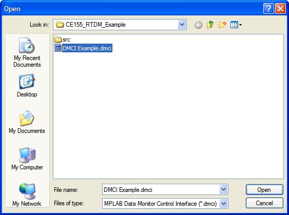
6. Click to load the profile, as shown in Figure 2-9. The Open dialog
appears, as shown in Figure 2-10.
FIGURE 2-9: BLANK DMCI PROJECT
DS70567A-page 14 © 2008 Microchip Technology Inc.Getting Started
7. Double-click DMCI Example.dmci to open the project, as shown in Figure 2-10.
FIGURE 2-10: OPENING THE DMCI PROJECT
8. Configure the communication properties by selecting DMCI>Remote
Communication from the MPLAB menu, as shown in Figure 2-11.
FIGURE 2-11: OPENING THE DMCI REMOTE COMMUNICATION
PROPERTIES
a) As shown in Figure 2-12, verify the serial communication settings. Make sure
that the settings match the RTDM configuration and the COM port number
assigned to the serial port. The COM PORT should be set to your COM port,
and the BAUD RATE should be set to 115200.
© 2008 Microchip Technology Inc. DS70567A-page 15Real-Time Data Monitor User’s Guide
FIGURE 2-12: SETTING THE DMCI REMOTE COMMUNICATION
PROPERTIES
b) Click TEST. The DETECTED message should appear. If not, make sure that
all of the RTDM settings are correct, you can verify this in the RTDMUSER.h
file, which can be found in your MPLAB project window. Note that your
device must be running for this test to work.
c) Make sure that the RTDM settings match the DMCI communication settings.
Check your hardware and double check the PC communication settings
again.
d) As shown in Figure 2-13, select the Enable Communication Option and
Transmit Individual Control Settings On Change options, and then click
OK.
FIGURE 2-13: DMCI REMOTE COMMUNICATION PROPERTIES
DS70567A-page 16 © 2008 Microchip Technology Inc.Getting Started
9. Modify and record variables at run time.
a) In the DMCI window, click the OFF button above the Snapshot button to turn
the Snapshot feature on. This feature will record the value of “MyVariable”
into the SnapShotBuffer.
b) Click to update the plot.
c) You can modify the Frequency and Amplitude by moving the sliders.
d) You can turn the board LEDs ON or OFF by clicking the LED buttons.
e) Any time you want to update the plot, repeat sub-steps “a” and “b”.
f) You can save the DMCI parameters for future use by clicking .
FIGURE 2-14: MODIFYING AND RECORDING VARIABLES AT RUN TIME
© 2008 Microchip Technology Inc. DS70567A-page 17Real-Time Data Monitor User’s Guide
2.2 ADDING THE REAL-TIME DATA MONITOR TO AN APPLICATION
This section describes the steps required to add RTDM into a user’s application code.
1. Copy the RTDM.c, RTDM.h and RTDMUSER.h files from the RTDM code
example project to your project folder.
FIGURE 2-15: ADDING THE RTDM FILES TO THE APPLICATION PROJECT
FOLDER
2. In your application MPLAB workspace, right-click the source file folder and add
the RTDM.c file, as shown in Figure 2-16.
FIGURE 2-16: ADDING THE RTDM.C FILE TO THE MPLAB PROJECT
DS70567A-page 18 © 2008 Microchip Technology Inc.Getting Started
3. In your application MPLAB workspace, right-click the header file folder and add
the RTDM.h and RTDM.h files, as shown in Figure 2-17.
FIGURE 2-17: ADDING FILES TO THE MPLAB PROJECT
4. Open the RTDMUSER.h file and define the values for the RTDM macros, as
shown in Example 2-1.
EXAMPLE 2-1: DEFINING VALUES FOR RTDM
© 2008 Microchip Technology Inc. DS70567A-page 19Real-Time Data Monitor User’s Guide
5. If the DMCI Data Viewer is activated, it is required to create a buffer for each
graph in order to plot the data snapshot. Also, declare the Boolean variables
required to trigger the data recorder, as shown in Example 2-2.
EXAMPLE 2-2: ALLOCATION MEMORY FOR THE DATA BUFFERS
6. Call the RTDM_Start() function at the beginning of your main function. If you
are using a dsPIC DSC device that has a PPS module, it is also required to
assign the UART port pins as shown in Example 2-3.
EXAMPLE 2-3: ADDING THE RTDM_Start() FUNCTION
DS70567A-page 20 © 2008 Microchip Technology Inc.Getting Started
7. If the polling method is defined, add the RTDM_ProcessMsgs() function to the
main loop, as shown in Example 2-4. Otherwise, if the interrupt method is
selected, proceed to the next step.
Note: In the polling method, the RTDM state machine will be called as soon as
the RTDM_ProcessMsgs() function is called. Therefore, the incoming and
outgoing messages would not be processed until this function is called. It is
strongly recommended to call the RTDM_ProcessMsgs() function before
10 ms have elapsed.
In the interrupt method, the RTDM state machine will be called as soon
as an incoming message is received. If using the interrupt method, it is
recommended to enable the nested interrupt method.
EXAMPLE 2-4: ADDING THE RTDM_ProcessMsgs() FUNCTION
© 2008 Microchip Technology Inc. DS70567A-page 21Real-Time Data Monitor User’s Guide
8. Record the variables on the buffers, as shown in Example 2-5.
EXAMPLE 2-5: FILLING THE BUFFERS
9. Create the DMCI project.
a) Enable the DMCI tool by selecting Tools>3 DMCI - Data Monitor Control
Interface, as shown in Figure 2-18.
FIGURE 2-18: ENABLING THE DMCI TOOL
b) Reset the DMCI controls by selecting the following options from the MPLAB
IDE menu, as shown in Figure 2-19:
• DMCI>Reset>Dynamic Controls>All
• DMCI>Reset>Dynamic Data Input>All
• DMCI>Reset>Dynamic Data Views>All
DS70567A-page 22 © 2008 Microchip Technology Inc.Getting Started
FIGURE 2-19: RESETTING THE DMCI CONTROLS
c) Add variables on the DMCI Dynamic Data Control window:
1. Enable the slider by checking the Slider box.
2. Open the Dynamic Data Control Properties menu by right-clicking the
active slider (as shown in Figure 2-20).
3. In the global symbols window, select the variable to be controlled.
4. Set the variable format and the maximum and minimum levels.
5. Click OK to save your changes.
FIGURE 2-20: OPENING THE DYNAMIC DATA CONTROL PROPERTIES
© 2008 Microchip Technology Inc. DS70567A-page 23Real-Time Data Monitor User’s Guide
d) Plot the variables in the DMCI Dynamic Data View window.
1. In the DMCI project window, select the Dynamic Data View tab.
2. Enable the graph by checking the graph box.
3. Right-click the active graph and select the configure data source option,
as shown in Figure 2-21.
4. In the global symbols window, select the buffer to be plotted.
5. Click OK to save your changes.
Note: It is required to compile the project before adding variables to the DMCI
project. DMCI utilizes the .map file to obtain the variables information.
FIGURE 2-21: SELECTING THE CONFIGURE DATA SOURCE OPTION
DS70567A-page 24 © 2008 Microchip Technology Inc.Getting Started
2.3 APPLICATION TIPS AND HINTS
The following are a few tips to consider when using the RTDM code with DMCI.
• Do not write to the data buffer while transmitting its contents. This will corrupt the
calculation of the CRC16 checksum, and therefore, the message will be discarded
by the host PC. To prevent this situation, always use a triggering condition (either
by software or hardware) to enable and disable writing the data buffer.
• To reduce the bit rate error, always make sure that the FCY frequency is a multiple
of the selected baud rate. A 7.37 MHz oscillator provides different values that are
multiples of the DMCI baud rates.
• When defining the data buffers, make sure that the compiler allocates the buffers
in an unused RAM section. Use the “aligned” attribute as much as possible. For
more information on this attribute, refer to the “MPLAB® C COMPILER for PIC24
MCUs and dsPIC® DSCs User’s Guide” (DS51284).
• To avoid user code malfunction, the priority of the UART interrupt used by the
RTDM should be lower than the critical timing interrupts used by the user’s
application software.
• Make sure that the memory data model is selected according to the size of the
data buffers. While using the RTDM in an application, the compiler should be
directed to use the most adequate data memory model according to the dsPIC
DSC device and the amount of data desired to display on the DMCI data view.
This is particularly useful in dsPIC DSC devices with a considerable size of RAM.
The following procedure describes the steps required to change the memory model.
1. From the MPLAB IDE menu, select Project>Build Options>Project, as shown in
Figure 2-22.
FIGURE 2-22: SELECTING PROJECT BUILD OPTIONS
© 2008 Microchip Technology Inc. DS70567A-page 25Real-Time Data Monitor User’s Guide
2. Click the MPLAB C30 tab and set the following options. From the Categories
drop-down list, select Memory Model, and then select the appropriate data
model according to the available RAM and the size of the RTDM data buffers.
The selection is shown in Figure 2-23.
FIGURE 2-23: ASSIGNING THE MEMORY DATA MODEL
DS70567A-page 26 © 2008 Microchip Technology Inc.REAL-TIME DATA MONITOR
USER’S GUIDE
Chapter 3. Application Programming Interface (API)
This chapter describes in detail the Application Programming Interface (API) functions
and constants that are available in the Real-Time Data Monitor.
3.1 API FUNCTIONS AND CONSTANTS
The functions and constants are listed below followed by their individual detailed
descriptions.
• RTDM_Start()
• RTDM_ProcessMsgs()
• CloseRTDM()
• RTDM_CumulativeCrc16()
• RTDM_FCY
• RTDM_BAUDRATE
• RTDM_UART
• RTDM_UART_PRIORITY
• RTDM_RXBUFFERSIZE
• RTDM_MAX_XMIT_LEN
• RTDM_POLLING
• RTDM_MIN_CODE_SIZE
© 2008 Microchip Technology Inc. DS70567A-page 27Real-Time Data Monitor User’s Guide
RTDM_Start()
Description
This function initializes the UART that is to be used to exchange data with the host PC.
Some processors may have two UART modules; therefore, it is required to specify
which UART module is to be used by RTDM.
Include
RTDM.h
RTDMUSER.h
Prototype
int RTDM_Start();
Arguments
None.
Return Value
0 if initialization process was successful
-1 if initialization process failed
RTDM_ProcessMsgs()
Description
This function processes the message received, and then executes the required task.
These tasks are reading a specific memory location, writing a specific memory location,
receiving a communication link sanity check command, or are querying for the size of
the buffers.
Include
RTDM.h
RTDMUSER.h
Prototype
int RTDM_ProcessMsgs();
Arguments
None.
Return Values
0 if there is no message to be processed
-1 if a message is being processed
DS70567A-page 28 © 2008 Microchip Technology Inc.Application Programming Interface (API)
CloseRTDM()
Description
This function closes the UART used to exchange data with the host PC.
Include
RTDM.h
RTDMUSER.h
Prototype
int RTDM_Close();
Arguments
None.
Return Values
Returns ‘0’ when the UART module was successfully closed.
RTDM_CumulativeCrc16()
Description
This function calculates the polynomial for the checksum byte. There are two
approaches to calculate this number.
1. “On-the-fly” every time. Saves code space because no const table is required.
This approach saves code space but yields slower throughput performance.
2. Using a coefficients table. This approach has faster performance but consumes
a higher amount of program memory.
Include
RTDM.h
RTDMUSER.h
Prototype
unsigned int RTDM_CumulativeCrc16 (unsigned char *buf, unsigned
int u16Length, unsigned int u16CRC);
Arguments
unsigned char *buf A pointer to the state memory for the
data to be used on the checksum calculation
unsigned int u16Length Number of bytes to be computed
unsigned int u16CRC Polynomial value used to calculate the CRC16
checksum
Return Values
CRC16 checksum value
© 2008 Microchip Technology Inc. DS70567A-page 29Real-Time Data Monitor User’s Guide
RTDM_FCY
Description
This constant defines the system operating frequency, whose value is used to calculate
the value of the BRG register.
Value
System Frequency
RTDM_BAUDRATE
Description
This constant defines the desired baud rate for the UART module to be used by RTDM.
Value
Available options are 38400, 57600, 115200, 230400 and 460800.
Note: UART modules can support higher baud rates, please refer to your trans-
ceiver specifications to check if your hardware supports higher baud rates.
RTDM_UART
Description
This constant defines the UART module to be used by RTDM. It has only two possible
values: 1 or 2
Value
Depending on the dsPIC DSC device it could be 1 or 2.
RTDM_UART_PRIORITY
Description
This constant defines the UART receiver interrupt priority assigned to receive the
RTDM messages.
Value
1 to 7
DS70567A-page 30 © 2008 Microchip Technology Inc.Application Programming Interface (API)
RTDM_RXBUFFERSIZE
Description
This constant defines the buffer size used by RTDM to handle messages.
Value
32
RTDM_MAX_XMIT_LEN
Description
This constant defines the size in bytes of the maximum number of bytes allowed in the
RTDM protocol frame.
Value
4096
RTDM_POLLING
Description
This constant defines the mode that the RTDM will be operating in the user’s
application. If it is set to YES, the user should place the RTDM_ProcessMsgs()
function in the main loop. In order to make sure that the messages are being
processed, it is recommended that the main loop always polls this function as fast as
possible (minimum 10 ms).
If it is set to NO, the RTDM_ProcessMsgs() function will be called on the UART
receiver Interrupt Service Routine (ISR). If multiple interrupts are enabled, it is required
to activate the nested interrupts mode on the dsPIC DSC device.
Value
YES or NO
© 2008 Microchip Technology Inc. DS70567A-page 31Real-Time Data Monitor User’s Guide
RTDM_MIN_CODE_SIZE
Description
This constant defines the Cyclic Redundancy Check (CRC) algorithm calculation
minimum code size. If it is set to YES, the RTDM library will be built including a
precalculated polynomial table for the CRC algorithm. This method reduces the device
CPU throughput required to calculate the CRC16 checksum.
If it is set to NO, the CRC16 value is calculated from scratch and the predefined poly-
nomial values would not be loaded into the program memory. This mode saves 768
bytes of code, but requires more device CPU throughput to calculate the CRC16
checksum.
Value
YES or NO
DS70567A-page 32 © 2008 Microchip Technology Inc.REAL-TIME DATA MONITOR
USER’S GUIDE
Chapter 4. Protocol
This chapter describes the RTDM protocol specification, which is used to debug dsPIC
DSC devices and PIC24H embedded applications at run-time. The RS-232 protocol
utilized by the RTDM is a set of simple binary structures and conventions, enabling a
data exchange between a personal computer and a target device. The serial frame
definition is: 1 start bit, 8 data bits, 1 parity bit and 1 stop bit. The maximum serial
transfer rate is 460800 bps. Topics covered include:
• The Protocol Model
• Commands
• ERROR Code
• Files
4.1 THE PROTOCOL MODEL
The communication model is based on the GDB Remote Serial Protocol, which is a
single master-slave protocol with some modifications according to the nature of the
application. This protocol is based on a basic principle – the host PC sends a message
with a command and its arguments, and then the target replies with the operation status
code and return data. The target device never initiates communication; its replies are
specified and always have a known fixed length.
All GDB commands and responses are sent as a packet. A packet is introduced with
the character ‘$’, the actual packet-data, and the terminating character ‘#’ followed by
a two-digit checksum. For example:
$packet-data#checksum
The two-digit checksum is a CRC16 calculation of all characters between the leading
‘$’ and the trailing ‘#’. When either the host or the target device receives a packet, the
first response expected is an acknowledgment: either ‘+’ (to indicate the package was
received correctly) or ‘-’ (to request retransmission).
The host sends commands, and the target (RTDM incorporated in your program) sends
a response. In the case of step and continue commands, the response is only sent
when the operation has completed. The packet-data consists of a sequence of
characters with the exception of ‘#’ and ‘$’. These characters are the commands and
the data required to execute those commands.
© 2008 Microchip Technology Inc. DS70567A-page 33Real-Time Data Monitor User’s Guide
4.2 COMMANDS
The command codes supported by the RTDM protocol are listed in Table 4-1.
TABLE 4-1: COMMANDS SUPPORTED BY RTDM
Function Data Access ASCII Code Code (Hex value)
Read Memory 16-bit word m 6D
Write Memory 16-bit word M 4D
Check Communication Link Sanity 16-bit word s 73
4.2.1 Read Memory Command
This function code is used to read from 1 to 65536 contiguous RAM locations on the
target device. The Host Request specifies the starting register address and the number
of memory locations formatted in little-endian format. The structure of this command is
shown in Table 4-2 and Table 4-3.
TABLE 4-2: HOST PC REQUEST
Size in Frame
Frame Arrangements ASCII Code Possible Values
(Bytes)
Start Code $ 1 0x24
Function Code m 1 0x6D
Starting Address in [XXXXXXXX] 4 0x00000000-0xFFFFFFFF
little-endian format
Number Of Bytes in [XXXX] 2 0x0000-0xFFFF
little-endian format (N)
End Of Message Code # 1 0x23
CRC16L [XX] 1 0x00-0xFF
CRC16H [XX] 1 0x00-0xFF
TABLE 4-3: TARGET DEVICE REPLY
Size in Frame
Frame Arrangements ASCII Code Possible Values
(Bytes)
Reply Code + 1 0x2B
Start Code $ 1 0x24
Memory Values in [XX]….[XX] Nx2 0x00-0xFF
little-endian format
End Of Message Code # 1 0x23
CRC16L [XX] 1 0x00-0xFF
CRC16H [XX] 1 0x00-0xFF
An example of reading the 16-bit memory location 0x00001234 is shown in
Example 4-1.
EXAMPLE 4-1:
Host PC Command:
$m432100002000#[CRC16]
Target Device Reply:
+$EFBE#[CRC16]
DS70567A-page 34 © 2008 Microchip Technology Inc.Protocol
4.2.2 Write Memory
This function code is used to write a block of contiguous RAM locations (1 to 65536
registers) on the target device. The requested written values are specified in the
packet-data field. The structure of this command is shown in Table 4-4 and Table 4-5.
TABLE 4-4: HOST PC REQUEST
Size in Frame
Frame Arrangements ASCII Code Possible Values
(Bytes)
Start Code $ 1 0x24
Function Code M 1 0x4D
Starting Address in [XXXXXXXX] 4 0x00000000-0xFFFFFFFF
little-endian format
Number Of Bytes in [XXXX] 2 0x0000-0xFFFF
little-endian format (N)
Values to be written in [XX] Nx2 0x00-0xFF
little-endian format
End Of Message Code # 1 0x23
CRC16L [XX] 1 0x00-0xFF
CRC16H [XX] 1 0x00-0xFF
TABLE 4-5: TARGET DEVICE REPLY
Size in Frame
Frame Arrangements ASCII Code Possible Values
(Bytes)
Reply Code + 1 0x2B
Start Code $ 1 0x24
Command Acknowledge O 1 0x4F
Command Acknowledge K 1 0x4B
End Of Message Code # 1 0x23
CRC16L [XX] 1 0x00-0xFF
CRC16H [XX] 1 0x00-0xFF
An example of writing 0xBEEF value to the memory location 0x00001234 is shown in
Example 4-2.
EXAMPLE 4-2:
Host PC Command:
$M43210000EFBE#[CRC16]
Target Device Reply:
+$OK#[CRC16]
© 2008 Microchip Technology Inc. DS70567A-page 35Real-Time Data Monitor User’s Guide
4.2.3 Communication Link Sanity Check Command
This command is used to check the link status and verify that there is a target device
attached. The structure of this command is shown in Table 4-6 and Table 4-7.
TABLE 4-6: HOST PC REQUEST
Size in Frame
Frame Arrangements ASCII Code Possible Values
(Bytes)
Start Code $ 1 0x24
Function Code s 1 0x73
End Of Message Code # 1 0x23
CRC16L [XX] 1 0x00-0xFF
CRC16H [XX] 1 0x00-0xFF
TABLE 4-7: TARGET DEVICE REPLY
Size in Frame
Frame Arrangements ASCII Code Possible Values
(Bytes)
Reply Code + 1 0x2B
Start Code $ 1 0x24
Memory Values RTDM 4 0x5254444D
End Of Message Code # 1 0x23
CRC16L [XX] 1 0x00-0xFF
CRC16H [XX] 1 0x00-0xFF
An example of link sanity request and response is shown in Example 4-3.
EXAMPLE 4-3:
Host PC Command:
$s#[CRC16]
Target Device Reply:
+$RTDM#[CRC16]
DS70567A-page 36 © 2008 Microchip Technology Inc.Protocol
4.3 ERROR CODE
When the host PC sends a request to the target device it expects a normal response.
One of four possible events can occur from the master’s query:
• If the target device receives the request without a communication error, and can
handle the query normally, it returns a normal response.
• If the target device does not receive the request due to a communication error, no
response is returned. The host PC program will eventually process a time-out
condition for the request.
• If the target device receives the request, but detects a communication error
(parity, CRC, etc.), no response is returned. The Host PC program will eventually
process a time-out condition (after 10 ms have elapsed) for the request.
• If the target device receives the request without a communication error, but cannot
handle it (for example, if the request is to read a nonexistent output or register),
the target device will return an exception response informing to the host PC the
nature of the error.
In a normal response, the target device replies with an “OK” command. In an exception
response, the target device replies with the “E” command plus the Error code. Table 4-8
shows the possible error code and its meaning.
TABLE 4-8: ERROR CODE
Code Name Meaning
01 Illegal Function The function code received in the query is not an
allowable action for the target device. It could also
indicate that the target device is in the wrong state
to process a request of this type, for example,
because it has not been configured and is being
asked to return register values.
An example of an error reply when a command is not supported is shown in
Example 4-4.
EXAMPLE 4-4:
-$E01#[CRC16]
4.3.1 Cyclic Redundancy Check (CRC) Generation
The CRC field is two bytes, containing a 16-bit binary value. The CRC value is
calculated by the transmitting device, which appends the CRC to the message. The
device that receives, recalculates a CRC during receipt of the message, and compares
the calculated value to the actual value it received in the CRC field. If the two CRC
values are not equal, an error is generated.
The CRC is started by first preloading a 16-bit register to all ‘1’s. Then, a process
begins of applying successive 8-bit bytes of the message to the current contents of the
register. Only the eight bits of data in each character are used for generating the CRC.
Start and stop bits and the parity bit, do not apply to the CRC.
During generation of the CRC, each 8-bit character is exclusive ORed with the register
contents. Then, the result is shifted in the direction of the Least Significant bit (LSb),
with a zero filled into the Most Significant bit (MSb) position. The LSb is extracted and
examined. If the LSb was a ‘1’, the register is then exclusive ORed with a preset, fixed
value. If the LSb was a ‘0’, no exclusive OR takes place.
© 2008 Microchip Technology Inc. DS70567A-page 37Real-Time Data Monitor User’s Guide
This process is repeated until eight shifts have been performed. After the last (eighth)
shift, the next 8-bit character is exclusive ORed with the register’s current value, and
the process repeats for eight more shifts as described above. The final content of the
register, after all the characters of the message have been applied, is the CRC value.
4.3.1.1 CALCULATING CRC
The steps for calculating a CRC are as follows:
1. Load a 16-bit register with FFFF hex (all ‘1’s). Call this the CRC register.
2. Exclusive OR the first 8-bit byte of the message with the low-order byte of the
16-bit CRC register, putting the result in the CRC register.
3. Shift the CRC register one bit to the right (toward the LSb), zero-filling the MSb.
Extract and examine the LSb.
4. If the LSb is ‘0’, repeat Step 3 (another shift). Otherwise, if the LSB is ‘1’,
Exclusive OR the CRC register with the polynomial value 0xA001
(1010 0000 0000 0001).
5. Repeat steps 3 and 4 until eight shifts have been performed. When this is done,
a complete 8-bit byte will have been processed.
6. Repeat steps 2 through 5 for the next 8-bit byte of the message. Continue doing
this until all bytes have been processed.
7. The final content of the CRC register is the CRC value.
8. When the CRC is placed into the message, its upper and lower bytes must be
swapped.
DS70567A-page 38 © 2008 Microchip Technology Inc.Protocol
4.4 FILES
The RTDM code is contained in three files: RTDM.c, RTDM.h, and RTDMUSER.h. In
addition, RTDM also requires the dsPIC Peripheral Library file (libpic30-coff.a).
This library provides the UART initialization routines, the send buffer routines, and the
transmit buffer routines.
The RTDM.c file contains the RTDM source code and defines the state machine and
functions required to receive and send commands to and from the host.
The RTDM.h file contains the RTDM function definitions. It also calculates the baud rate
deviation for the selected target device system frequency (FCY). When the delta
between the FCY and the selected RTDM_BAUDRATE is higher by 2% or lower than 2%,
the compiler generates an error message.
The RTDMUSER.h file defines the RTDM operational mode. This file sets the
communication baud rate, the UART module to be used, the UART receiver interrupt
priority, the command-reception buffer size, the maximum number of bytes to be sent,
the form RTDM state machine is called (polled or interrupt-based), and the CRC16
calculation method.
© 2008 Microchip Technology Inc. DS70567A-page 39Real-Time Data Monitor User’s Guide NOTES: DS70567A-page 40 © 2008 Microchip Technology Inc.
REAL-TIME DATA MONITOR
                                                                USER’S GUIDE

                        Chapter 5. DMCI Operating Modes
                       This chapter describes three different DMCI operating modes. Topics covered include:
                       • RTDM Mode
                       • Data Capture Mode
                       • Combine Mode

5.1      RTDM MODE
                       This DMCI mode acquires and modifies data at run time using the alternative
                       communication link explained in Chapter 1. “Introduction”. An application example is
                       shown in Figure 5-1.
                       The steps required to implement this mode are explained in Section 2.1 “Running the
                       Real-Time Data Monitor Code Example CE155” and Section 2.2 “Adding the
                       Real-Time Data Monitor to an Application”.

FIGURE 5-1:            RTDM-BASED APPLICATION EXAMPLE

               MPLAB® DMCI                                     RTDM software running in
                                                                user’s application code

                                         USB or RS-232

© 2008 Microchip Technology Inc.                                                           DS70567A-page 41
Real-Time Data Monitor User’s Guide
5.2 DATA CAPTURE MODE
This mode utilizes the MPLAB REAL ICE In-Circuit Emulator and the on-chip
debugging module (ICSP™) to read data from RAM. It acquires data as fast as 50 µs
and periodically displays the acquired data using the DMCI dynamic data view graphs.
It was developed for reading RAM contents without halting execution. This DMCI mode
only runs under Debug mode. The number of variables that can be plotted using this
method depend on the number of hardware breakpoints available on the target device.
An application example is shown in Figure 5-2.
FIGURE 5-2: DATA CAPTURE APPLICATION EXAMPLE
MPLAB® DMCI Running Target device running
in Debug mode in Debug mode
MPLAB REAL ICE™
In-Circuit Emulator
Emulator Pod
For more information on how to implement this mode, refer to the DMCI Help, as shown
in Figure 5-3.
FIGURE 5-3: OPENING THE DMCI HELP FILE
DS70567A-page 42 © 2008 Microchip Technology Inc.DMCI Operating Modes
5.3 COMBINE MODE
This mode combines the Data Capture and the RTDM running under Debug mode. It
utilizes the MPLAB REAL ICE In-Circuit Emulator and the on-chip debugging module
(ICSP) to continuously read data from the RAM. It uses RTDM to read and write
variables that are updated faster than 50 µs. An application example is shown in
Figure 5-4.
FIGURE 5-4: COMBINED MODE APPLICATION EXAMPLE
MPLAB® DMCI running Target device running
in Debug mode in Debug mode
MPLAB REAL ICE™
In-Circuit Emulator
Physical link
for RTDM
USB or RS-232
Emulator Pod
For more information on how to add the data capture mode to the RTDM mode, refer
to the DMCI Help. Figure 5-5 shows the location of the compiled Help file.
FIGURE 5-5: DMCI HELP FILE PATH
© 2008 Microchip Technology Inc. DS70567A-page 43Real-Time Data Monitor User’s Guide NOTES: DS70567A-page 44 © 2008 Microchip Technology Inc.
REAL-TIME DATA MONITOR
                                                                                            USER’S GUIDE

                                                                            Index
A                                                                                  E
API Constants                                                                      Error Code................................................................ 37
    RTDM_BAUDRATE.............................................. 30
                                                                                   G
    RTDM_FCY......................................................... 30
    RTDM_MAX_XMIT_LEN ..................................... 31                     GDB Remote Serial Protocol ................................... 33
    RTDM_MIN_CODE_SIZE ................................... 32                      I
    RTDM_POLLING ................................................ 31
                                                                                   Internet Address......................................................... 5
    RTDM_RXBUFFERSIZE ..................................... 31
    RTDM_UART ...................................................... 30            M
    RTDM_UART_PRIORITY ................................... 30                      Microchip Internet Web Site ....................................... 5
API Functions
    CloseRTDM() .................................................. 29              P
    RTDM_CumulativeCrc16() .......................... 29                           Protocol Commands................................................. 34
    RTDM_ProcessMsgs() ................................... 28                          Communication Link Sanity Check ................... 36
    RTDM_Start() ................................................ 28                   Read Memory ................................................... 34
Application Programming Interface (API)..............1, 27                             Write Memory.................................................... 35
Application Tips........................................................ 25        Protocol Model ......................................................... 33
C                                                                                  R
Calculating CRC ...................................................... 38          Reading, Recommended ........................................... 4
Customer Notification Service.................................... 5                Real-Time Data Monitor (RTDM) ............................... 7
Customer Support ...................................................... 5              Adding RTDM to an Application........................ 18
                                                                                       Code Files......................................................... 39
D                                                                                      Features.............................................................. 8
Data Monitor and Control Interface (DMCI) ............... 7                            Getting Started.................................................... 9
DMCI Operating Modes ........................................... 41                    Protocol Specification ....................................... 33
    Combine ........................................................... 43             Running the RTDM Code Example CE155......... 9
    Data Capture .................................................... 42               System Requirements......................................... 8
    RTDM ............................................................... 41
Documentation                                                                      W
    Conventions ........................................................ 3         Warranty Registration ................................................ 3
    Layout ................................................................. 1     WWW Address........................................................... 5

© 2008 Microchip Technology Inc.                                                                                                      DS70567A-page 45
Worldwide Sales and Service
AMERICAS ASIA/PACIFIC ASIA/PACIFIC EUROPE
Corporate Office Asia Pacific Office India - Bangalore Austria - Wels
2355 West Chandler Blvd. Suites 3707-14, 37th Floor Tel: 91-80-4182-8400 Tel: 43-7242-2244-39
Chandler, AZ 85224-6199 Tower 6, The Gateway Fax: 91-80-4182-8422 Fax: 43-7242-2244-393
Tel: 480-792-7200 Harbour City, Kowloon India - New Delhi Denmark - Copenhagen
Fax: 480-792-7277 Hong Kong Tel: 45-4450-2828
Tel: 91-11-4160-8631
Technical Support: Tel: 852-2401-1200 Fax: 45-4485-2829
Fax: 91-11-4160-8632
http://support.microchip.com
Fax: 852-2401-3431 France - Paris
Web Address: India - Pune
Australia - Sydney Tel: 91-20-2566-1512 Tel: 33-1-69-53-63-20
www.microchip.com
Tel: 61-2-9868-6733 Fax: 91-20-2566-1513 Fax: 33-1-69-30-90-79
Atlanta Fax: 61-2-9868-6755
Duluth, GA Japan - Yokohama Germany - Munich
China - Beijing Tel: 81-45-471- 6166 Tel: 49-89-627-144-0
Tel: 678-957-9614
Tel: 86-10-8528-2100 Fax: 49-89-627-144-44
Fax: 678-957-1455 Fax: 81-45-471-6122
Fax: 86-10-8528-2104 Italy - Milan
Boston Korea - Daegu
China - Chengdu Tel: 39-0331-742611
Westborough, MA Tel: 82-53-744-4301
Tel: 86-28-8665-5511 Fax: 82-53-744-4302 Fax: 39-0331-466781
Tel: 774-760-0087
Fax: 86-28-8665-7889 Netherlands - Drunen
Fax: 774-760-0088 Korea - Seoul
China - Hong Kong SAR Tel: 82-2-554-7200 Tel: 31-416-690399
Chicago
Itasca, IL Tel: 852-2401-1200 Fax: 82-2-558-5932 or Fax: 31-416-690340
Tel: 630-285-0071 Fax: 852-2401-3431 82-2-558-5934 Spain - Madrid
Fax: 630-285-0075 China - Nanjing Tel: 34-91-708-08-90
Malaysia - Kuala Lumpur
Tel: 86-25-8473-2460 Fax: 34-91-708-08-91
Dallas Tel: 60-3-6201-9857
Addison, TX Fax: 86-25-8473-2470 Fax: 60-3-6201-9859 UK - Wokingham
Tel: 972-818-7423 China - Qingdao Tel: 44-118-921-5869
Malaysia - Penang
Fax: 972-818-2924 Tel: 86-532-8502-7355 Fax: 44-118-921-5820
Tel: 60-4-227-8870
Detroit Fax: 86-532-8502-7205 Fax: 60-4-227-4068
Farmington Hills, MI China - Shanghai Philippines - Manila
Tel: 248-538-2250 Tel: 86-21-5407-5533 Tel: 63-2-634-9065
Fax: 248-538-2260 Fax: 86-21-5407-5066 Fax: 63-2-634-9069
Kokomo China - Shenyang Singapore
Kokomo, IN Tel: 86-24-2334-2829 Tel: 65-6334-8870
Tel: 765-864-8360 Fax: 86-24-2334-2393 Fax: 65-6334-8850
Fax: 765-864-8387
China - Shenzhen Taiwan - Hsin Chu
Los Angeles Tel: 86-755-8203-2660 Tel: 886-3-572-9526
Mission Viejo, CA Fax: 86-755-8203-1760 Fax: 886-3-572-6459
Tel: 949-462-9523
China - Wuhan Taiwan - Kaohsiung
Fax: 949-462-9608
Tel: 86-27-5980-5300 Tel: 886-7-536-4818
Santa Clara Fax: 86-27-5980-5118 Fax: 886-7-536-4803
Santa Clara, CA
China - Xiamen Taiwan - Taipei
Tel: 408-961-6444
Tel: 86-592-2388138 Tel: 886-2-2500-6610
Fax: 408-961-6445
Fax: 86-592-2388130 Fax: 886-2-2508-0102
Toronto
China - Xian Thailand - Bangkok
Mississauga, Ontario,
Tel: 86-29-8833-7252 Tel: 66-2-694-1351
Canada
Tel: 905-673-0699 Fax: 86-29-8833-7256 Fax: 66-2-694-1350
Fax: 905-673-6509 China - Zhuhai
Tel: 86-756-3210040
Fax: 86-756-3210049
01/02/08
DS70567A-page 46 © 2008 Microchip Technology Inc.You can also read