INFINEE Water chillers - Groupes d'eau Glacée - Tecumseh Products
←
→
Page content transcription
If your browser does not render page correctly, please read the page content below
INFINEE
          Water chillers
      Groupes d'eau Glacée

       CONTROL USER MANUAL
MANUEL D'UTILISATION DE LA REGULATION

ENGLISH……….………………………………………….....PAGE - 3 -

FRANÇAIS……………………………………………..……...PAGE - 33 -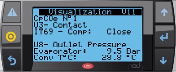
Control User Manual
                                                                             INFINEE chillers

Table of contents

1.   Warning ...................................................................................................................................... - 4 -
2.   Overview of the equipment ....................................................................................................... - 5 -
            Overview of the PLC .......................................................................................................... - 5 -
            Overview of PLC inputs/outputs ...................................................................................... - 6 -
            Overview of variable-frequency drives ........................................................................... - 8 -
            Communication ................................................................................................................. - 9 -
3.   Commissioning - Settings ...................................................................................................... - 10 -
            User interface ................................................................................................................... - 10 -
            Menu tree .......................................................................................................................... - 11 -
            Appearance of the home screen .................................................................................... - 11 -
            Main menu overview ....................................................................................................... - 12 -
            Access to sub-menus ..................................................................................................... - 13 -
            On_Off menu .................................................................................................................... - 14 -
            Settings menu .................................................................................................................. - 15 -
            Visualisation menu .......................................................................................................... - 16 -
            Clock menu ...................................................................................................................... - 19 -
                Information menu ........................................................................................................ - 21 -
                Configurations menu .................................................................................................. - 22 -
                Alarm menu: ................................................................................................................. - 22 -
                Indication of presence of a fault ................................................................................ - 22 -
                Viewing old "history" alarms ...................................................................................... - 23 -
                Password menu ........................................................................................................... - 24 -
4.   Start-up sequence ................................................................................................................... - 25 -
            Settings............................................................................................................................. - 25 -
            Alarm display menus ...................................................................................................... - 26 -
     4.2.1.         Fault present ............................................................................................................ - 26 -
     4.2.2.         History ...................................................................................................................... - 27 -
            Principles of regulation ................................................................................................... - 27 -
     4.3.1.         Regulating the water loop ....................................................................................... - 27 -
     4.3.2.         High-pressure regulation: ....................................................................................... - 28 -
5.   Appendix: Alarms list: ............................................................................................................ - 29 -

 Version: 2020-01                                 TECUMSEH EUROPE S&L
                                            2 av. Blaise Pascal, 38090 Vaulx Milieu                                           ENGLISH                  -3-
                                      Tel. : +33 (0)4 74 82 24 00 - www.tecumseh.com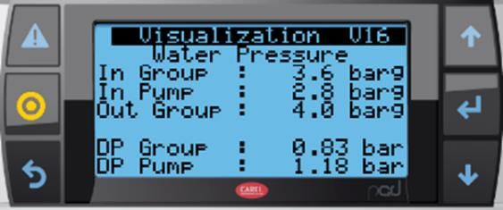
Control User Manual
                                                        INFINEE chillers

1.    Warning
        It is essential to understand and apply the instructions contained in this document before
beginning installation.
       For information relating to delivery of the chillers, refer to the "General Terms of Sale".
                Chillers must be transported and handled according to the instructions noted on their
                packaging and the information in this manual.

                       Qualified personnel must install this chiller and related equipment.

         Comply with the standards in force in the country where the chiller is installed and the rules of
the art for refrigeration and electrical connections.

        TECUMSEH EUROPE S.A. cannot be held responsible if installation and maintenance do not
comply with the instructions provided in this manual. As a result, operators must follow the instructions
contained in this document and the specific technical characteristics of the installation site.
Please pay attention to the scope of application and operation defined by TECUMSEH EUROPE SA.

        It is absolutely forbidden to operate this product outside the intended scope of operation.

        It is absolutely forbidden to climb onto the product or on the water inlet and outlet pipes.

        It is absolutely forbidden to start the chiller without correctly mounting all the safeguards.

        Do not install the product in a corrosive or explosive atmosphere

        Do not undertake any interventions without having turned off the product.

        Do not disconnect the safety devices.

 Version: 2020-01                       TECUMSEH EUROPE S&L
                                  2 av. Blaise Pascal, 38090 Vaulx Milieu                 ENGLISH        -4-
                            Tel. : +33 (0)4 74 82 24 00 - www.tecumseh.com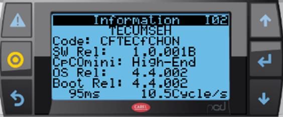
Control User Manual
INFINEE chillers
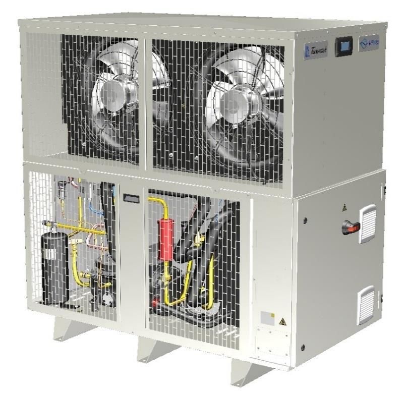
2. Overview of the equipment
The control system consists of:
• A programmable logic controller and a remote input/output module.
• A remote display connected to the PLC for the settings, for visualizing operation and starting
the chiller.
• A variable-frequency drive to control the compressor.
• A variable-frequency drive to control the pump.
• All electrical components are grouped in a waterproof electrical housing placed on one side of
the unit.
Below is a diagram of the main components of the electrical housing.
Overview of the PLC
The automatic processes are controlled by a C.pCO mini CAREL PLC and an extension consisting of
a C.pCOe CAREL module.
The PLC has the following characteristics:
• Supply: 24 VDC
• 10 universal inputs/outputs configurable to logic inputs, analogue inputs, logic outputs and
analogue outputs
• 6 relay logic outputs
• Integrated fieldbus/BMS port
• Built-in Ethernet port
• Integrated unipolar EXV electronic expansion valve control driver
• A Host for micro USB port and media
• CANOpen port for I/O extension
• A local display with 6 buttons
• A communication port for a pGD-type remote display
The C.pCOe plug-in has the following features:
• Supply: 24 VDC
• 10 universal inputs/outputs configurable to logic inputs, analogue inputs, logic outputs and
analogue outputs
• 6 relay logic outputs
• 1 RS485 port used to communicate with the main PLC
Version: 2020-01 TECUMSEH EUROPE S&L
2 av. Blaise Pascal, 38090 Vaulx Milieu ENGLISH -5-
Tel. : +33 (0)4 74 82 24 00 - www.tecumseh.com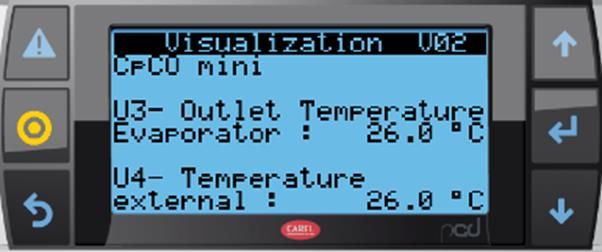
Control User Manual
                                                    INFINEE chillers

       Overview of PLC inputs/outputs
Main controller inputs/outputs: C.pCO mini HighEnd
 Universal inputs
 Channel Description                                                             Type
 U1         Suction temperature sensor                                           NTC
 U2         Discharge temperature sensor                                         NTC
 U3         Evaporator output temperature sensor at refrigerant side             NTC
 U4         Outdoor temperature sensor                                           NTC
 U5         Water inlet temperature sensor                                       NTC
 U6         Water outlet temperature sensor                                      NTC
 U7         Evaporation pressure                                                 4-20 mA
 U8         Condensation pressure                                                4-20 mA
 U9         Water pressure at pump inlet                                         4-20 mA
 U10        Water pressure at pump outlet                                        4-20 mA

 Digital inputs
 Channel Description                                              Type     State 0      State 1
 ID1         Remote start/stop                                    DI       Stop         Start
 ID2         Request to operate in ECO mode                       DI       Normal       Eco

 Digital output (relay)
 Channel Description                                              Type     State 0       State 1
 NO1         Oil crankcase heater                                 DO       Stop          Start
 NO2         PLC safety loop control                              DO       Safety        OK
 NO3         Bypass solenoid valve output                         DO       Open          Closed
 NO4         Fault feedback to client                             DO       OK            Fault
 NO5         Free                                                 DO       /             /
 NO6         Alarm feedback to client                             DO       OK            Fault

 Analog outputs
 Channel Description                                              Type     Variation
                                                                           3 V → min speed
 Y1        Fan speed of condenser No. 1                           0/10 V
                                                                           10 V → max speed
                                                                           3 V → min speed
 Y2        Fan speed of condenser No. 2                           0/10 V
                                                                           10 V → max speed

 Version: 2020-01                     TECUMSEH EUROPE S&L
                                2 av. Blaise Pascal, 38090 Vaulx Milieu              ENGLISH       -6-
                          Tel. : +33 (0)4 74 82 24 00 - www.tecumseh.com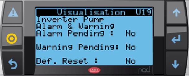
Control User Manual
                                                       INFINEE chillers

 Communication interfaces
 Channel  Description                                                  Type
 DISPLAY To remote pGD display                                         Modbus on RS485
             Dialog with supervisor or modem for remote                Modbus on IP
 ETH         management of the embedded Web server
             Modbus dialog to control compressor, pump and I/O         Modbus on RS485
 FB1         expansion card
                                                                       Unipolar EXV
 EXV         Electronic trigger

Inputs/outputs of remote module: C.pCOe
 Universal inputs
 Channel       Description                                 Type             State 0       State 1
 U1            LP pressure switch                          DI (NO)          Fault         OK
 U2            HP pressure switch                          DI (NO)          Fault         OK
 B3            IT69                                        DI (NO)          Fault         OK
 B4            Free
 B5            Free
 B6            Free
 B7            Free
               Evaporator output pressure sensor at                         4 mA → -1.0 bar
 B8            refrigerant side                            4-20 mA          20 mA → 12 bar
                                                                            4 mA → -0.5 bar
 B9           Water pressure at unit input                 4-20 mA          20 mA → 10 bar
 B10          Free

 Digital outputs (relays)
 Channel      Description                             Type            State 0           State 1
 NO1          Free
 NO2          Free
 NO3          Free
 NO4          Free
 NO5          Free
 NO6          Indication of active compressor         DO              Stop              Start

 Version: 2020-01                      TECUMSEH EUROPE S&L
                                 2 av. Blaise Pascal, 38090 Vaulx Milieu              ENGLISH       -7-
                           Tel. : +33 (0)4 74 82 24 00 - www.tecumseh.com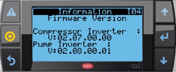
Control User Manual
                                                   INFINEE chillers

       Overview of variable-frequency drives
The variable-frequency drives used to control the compressor and the pump are made by ABB.
Variable-frequency drive for the compressor: ACS580

Variable-frequency drive for the pump: ACS380

These two drives are products manufactured by ABB, but they are configured to meet the specific
needs of the unit.

 Version: 2020-01                     TECUMSEH EUROPE S&L
                                2 av. Blaise Pascal, 38090 Vaulx Milieu            ENGLISH        -8-
                          Tel. : +33 (0)4 74 82 24 00 - www.tecumseh.com
Control User Manual
                                                     INFINEE chillers

       Communication

The CAREL PLC has two communication channels:
   • A Modbus RS485 network inside the unit

                      Modbus IP (Ethernet port) to monitoring

Slave
CAREL PLC
C.pCO mini
Master

                              Modbus RTU (RS485 port) inside the mini chiller

                              Variable-frequency                    Variable-frequency
C.pCOe plug-in                drive of compressor                   drive of pump
    Slave @ 01                      Slave @ 03                          Slave @ 02

Definition of the internal Modbus RTU communication network.
Components                                Type    Address
CAREL CPO mini PLC                       Master      00
C.pCOe plug-in                           Slave       01
Variable-frequency drive of pump         Slave       02
Variable-frequency drive of compressor   Slave       03

Communication speed           38.4 Kbps
Data bits                     8
Start bit                     None
Stop bit                      2

 Version: 2020-01                    TECUMSEH EUROPE S&L
                               2 av. Blaise Pascal, 38090 Vaulx Milieu               ENGLISH   -9-
                         Tel. : +33 (0)4 74 82 24 00 - www.tecumseh.com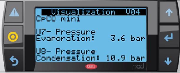
Control User Manual
                                                     INFINEE chillers

3.    Commissioning - Settings
During commissioning, a number of parameters must be filled in to allow the unit to meet the
installation requirements.
All settings are accessible on the human/machine interface present on the unit panel.

        User interface
Depending on the configuration, the PLC has a local display or no local display.
A standard feature on the Chiller is a remote display, placed externally above the electrical section,
allowing access to all parameters.
This display has the same function as the local display: pGD1-type monochrome semi-graphic display
(8 lines, 22 columns).
This display has 6 buttons.
The buttons can light up and can serve as indicator lights.

  Alarm indicator light                                                            Menu code
  and acknowledge
  button and access to                                                             Up/down buttons
  alarms                                                                           for navigation
                                                                                   and changes
 Sub-menu access
 button                                                                            Enter button for
                                                                                   validation and
 Back button to                                                                    access to
 previous menu                                                                     selection

The navigation buttons are used to navigate on a page if multiple settings are available on this page,
or to navigate to other pages.
When a parameter is editable, these buttons allow the value to be changed.
The Enter button validates a new parameter value.
The display is backlit to facilitate visibility.
The backlight turns off after 3 minutes of no action on the buttons.
Invitation screen, displayed only during the initialization phase of the PLC:

 Version: 2020-01                     TECUMSEH EUROPE S&L
                                2 av. Blaise Pascal, 38090 Vaulx Milieu              ENGLISH          - 10 -
                          Tel. : +33 (0)4 74 82 24 00 - www.tecumseh.com
Control User Manual
INFINEE chillers
Menu tree
To facilitate access, the menus are divided into 3 levels maximum. The most used menus are placed
first
Menu Menu Menu Menu Type of access Menu
Level 0 Level 1 Level 2 Level 3 code
Main menu Direct P
ON/OFF User password M
Instructions User password Co
Visualization Direct V
Clock User password H
Information Direct I
Configurations
Inputs/outputs Developer password Ca
Regulation Developer password Cb
EVD
Configuration Developer password Cca
Regulation Developer password Ccb
Custom Developer password /
Test Developer password T
Password Direct Password
After 30 seconds of inactivity on the HMI, the display automatically returns to the home screen.
Each screen has a unique code and this code is composed of the "menu code" followed by a
chronological number.
For alarm management, see chapter: 3.12
Appearance of the home screen
Menu displayed after the initialization phase.
This menu allows access to the other menus
Menu code
Operating mode
Operating pictograms
List of pictograms visible on the main menu
Water loop operation request
Cooling unit operation request Operating state of the water pump
Compressor operating state Bypass valve operating state
Condenser fan operating state Operation in frost-free mode
Version: 2020-01 TECUMSEH EUROPE S&L
2 av. Blaise Pascal, 38090 Vaulx Milieu ENGLISH - 11 -
Tel. : +33 (0)4 74 82 24 00 - www.tecumseh.comControl User Manual
INFINEE chillers
Main menu overview
From the home screen, some visualization functions can be accessed by pressing the buttons and
General menu
Menu 1
Display of current operating mode and
P01
active elements
Visualization of the setpoint, the water
temperature and the temperature
Menu 2 difference between the water inlet and
P02 outlet.
Visualization of the operating state of the
compressor and the pump.
Menu 3
Visualization of compressor operation.
P03
Menu 4
Visualization of pump operation.
P04
Menu 5 Compressor availability (delay times).
P05 Operating state of the crankcase heater.
Operating time
Menu 6 Display of operating times: these times
P06 are reset to 0 as soon as the element
stops.
Menu 7 Display language selection menu.
P07 The default language is French.
Version: 2020-01 TECUMSEH EUROPE S&L
2 av. Blaise Pascal, 38090 Vaulx Milieu ENGLISH - 12 -
Tel. : +33 (0)4 74 82 24 00 - www.tecumseh.comControl User Manual
INFINEE chillers
Access to sub-menus
Some functions can be accessed through sub-menus:
Access to the list of sub-menus by pressing
List of accessible sub-menus:
Starting up and stopping the unit
Setting of setpoints and certain operating parameters
Accessible through the "User" password
Display of measures useful to operation of the unit
Setting the date and time; setting the calendar; operating time consultation
Information about the product, software version, etc.
Settings of operating parameters.
Only accessible using the "Developer" password.
Access to tests and overrides on the unit.
Only accessible using the "Developer" password.
User and developer password setup menu
Version: 2020-01 TECUMSEH EUROPE S&L
2 av. Blaise Pascal, 38090 Vaulx Milieu ENGLISH - 13 -
Tel. : +33 (0)4 74 82 24 00 - www.tecumseh.comControl User Manual
INFINEE chillers
On_Off menu
This menu allows the unit to be started and stopped
Accessible with the "User" password.
Request for password.
Enter the User password to access the
following windows.
The developer password also allows
access to this menu.
Menu 1 Switching the unit from Start to Stop
M01 Or from Stop to Start
Operating state display
Menu 2 Selects the option to operate in Eco
M02 mode
CTM request displayed.
(1) To start cold generation, there are several possible cases:
Case 1: Control switch 009S05, installed inside the cabinet, is switched to "LOCAL"
Start-up is initiated by an action in menu M01
Case 2: Control switch 009S05, installed inside the cabinet, is switched to "REMOTE"
A contact between terminals X5.1 and X5.2 must be closed
Start-up is initiated by an action in menu M01
Case 3: Control switch 009S05, installed inside the cabinet, is switched to "OFF"
Start-up impossible.
A three-position switch 009S05 is installed in the electrical box.
"LOCAL" position
"OFF" position
"REMOTE" position
(2) When ECO mode is confirmed in this menu, the unit will only operate in economical mode, i.e.
a limited compressor operating frequency and a lower condenser fan speed.
Version: 2020-01 TECUMSEH EUROPE S&L
2 av. Blaise Pascal, 38090 Vaulx Milieu ENGLISH - 14 -
Tel. : +33 (0)4 74 82 24 00 - www.tecumseh.comControl User Manual
INFINEE chillers
Settings menu
Setting of setpoints and certain operating parameters. Accessible through the "User" password
Request a password.
Enter the User password to access the following
windows.
The developer password also allows access to
this menu.
Select the glycol level used on the water circuit.
Menu 1
Attention: the glycol level allows different
Co01
operating regimes on the water temperature.
Menu 2 Setting the temperature setpoint on the water
Co02 return.
Menu 3 Adjusting the desired temperature delta between
Co03 the water return and the water outlet.
Display of the setpoints according to the
Menu 4
parameters set above.
Co04
No modification possible
Menu 5 Adjustment of the offset around the setpoint for
Co05 starting up and stopping the compressor.
Display of the setpoints according to the
Menu 6
previously set parameters.
Co06
No modification possible.
Menu 7 Adjusting the compressor operating frequencies:
Co07 operating range between 25 Hz and 85 Hz.
Menu 8 Setting the NO or NF output type for alarm return
Co08 and compressor start-up indication
Version: 2020-01 TECUMSEH EUROPE S&L
2 av. Blaise Pascal, 38090 Vaulx Milieu ENGLISH - 15 -
Tel. : +33 (0)4 74 82 24 00 - www.tecumseh.comControl User Manual
INFINEE chillers
Visualisation menu
This menu allows visualisation of the PLC inputs/outputs and a number of values useful to the
understanding of the unit's operation.
No parameter changes can be done in this menu.
No password needed to access this menu.
Menu 1 Visualization of compressor suction and
V01 discharge temperatures
Menu 2 Visualization of evaporation and external
V02 temperatures
Menu 3 Visualization of water inlet and outlet
V03 temperatures
Menu 4 Visualization of evaporation and
V04 condensation pressures
Menu 5 Visualization of the water inlet and outlet
V05 pressures of the pump
Contact status:
Menu 6
Remote ON/OFF
V06
Remote ECO mode
Status of the compressor crankcase
Menu 7
heater
V07
Status of the controller safety output
Version: 2020-01 TECUMSEH EUROPE S&L
2 av. Blaise Pascal, 38090 Vaulx Milieu ENGLISH - 16 -
Tel. : +33 (0)4 74 82 24 00 - www.tecumseh.comControl User Manual
INFINEE chillers
Menu 8 Status of bypass solenoid valve
V08 Fault indication status
Menu 9 Control of condenser fans (between 0
V09 and 10 V)
LP and HP pressure switch status
Menu 10
(closed → OK)
V10
(open → triggered)
Compressor protection status
Menu 11
Evaporator outlet pressure in bar and
V11
converted to °C
Menu 12 Visualization of the water inlet pressure
V12 of the unit
Menu 13
Cooling capacity visualization
V13
Menu 14 Electronic expansion valve status and
V14 compressor overheating display
Water circuit status with pump
Menu 15
frequency, Water temperatures and
V15
pressure
Version: 2020-01 TECUMSEH EUROPE S&L
2 av. Blaise Pascal, 38090 Vaulx Milieu ENGLISH - 17 -
Tel. : +33 (0)4 74 82 24 00 - www.tecumseh.comControl User Manual
INFINEE chillers
Menu 16 Display of measured water pressures
V16 and pressure differences in the unit
Display of data provided by the pump's
Menu 17
variable-frequency drive and the
V17
compressor's variable-frequency drive.
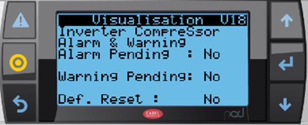
Display of alarms and warnings of the
compressor's variable-frequency drive.
Possibility of resetting a fault.
Menu 18
In case of a fault, display of the variable-
V18
frequency drive's fault code. Please
refer to the drive documentation to
interpret this code.
Display of the alarms and warnings of
the pump's variable-frequency drive.
Option to reset a fault.
Menu 19
In case of a fault, display of the variable-
V19
frequency drive's fault code. Please
refer to the drive documentation to
interpret this code.
Version: 2020-01 TECUMSEH EUROPE S&L
2 av. Blaise Pascal, 38090 Vaulx Milieu ENGLISH - 18 -
Tel. : +33 (0)4 74 82 24 00 - www.tecumseh.comControl User Manual
INFINEE chillers
Clock menu
This menu allows the setting of the date and time; setting the calendar; operating time consultation.
Accessible through the "User" password.
Request a password.
Enter the User password to access the
following windows.
The developer password also allows
access to this menu.
Changing the date and time on the PLC.
Menu 1
H01
Use the buttons , and
Operation planner for Monday
Option to select the Standard mode or
Menu 2
Eco mode. The choice of operation can
H02
be made on 4 time slots on the same
day.
Menu 3
Same as H02, for Tuesday
H03
Menu 4
Same as H02, for Wednesday
H04
Menu 5
Same as H02, for Thursday
H05
Menu 6
Same as H02, for Friday
H06
Menu 7
Same as H02, for Saturday
H07
Menu 8
Same as H02, for Sunday
H08
Menu 9 Select 4 special days in the year on
H09 which operation will be in Eco mode
Menu 10 Follows the H09 menu
H10 For selecting 2 extra special days
Vacation planner
Menu 11
Select periods for which operation will be
H11
in Eco mode
Version: 2020-01 TECUMSEH EUROPE S&L
2 av. Blaise Pascal, 38090 Vaulx Milieu ENGLISH - 19 -
Tel. : +33 (0)4 74 82 24 00 - www.tecumseh.comControl User Manual
INFINEE chillers
Menu 12 Number of operating hours accumulated
H12 since commissioning
Menu 13
Number of start-ups in the last 2 hours
H13
Menu 14
Number of start-ups in the last 24 hours
H14
Menu 15 Number of start-ups since
H15 commissioning
Menu 16
Option to reset the operating time to 0.
H16
Version: 2020-01 TECUMSEH EUROPE S&L
2 av. Blaise Pascal, 38090 Vaulx Milieu ENGLISH - 20 -
Tel. : +33 (0)4 74 82 24 00 - www.tecumseh.comControl User Manual
INFINEE chillers
Information menu
This menu provides information about the product, software version etc.
Password needed to access this menu.
Menu 1
General product information
I01
Menu 2
PLC information
I02
Menu 3
Information about the PLC plug-in.
I03
Information about the versions of
Menu 4 firmware for the compressor's and
I04 pump's variable-frequency drives.
Version: 2020-01 TECUMSEH EUROPE S&L
2 av. Blaise Pascal, 38090 Vaulx Milieu ENGLISH - 21 -
Tel. : +33 (0)4 74 82 24 00 - www.tecumseh.comControl User Manual
INFINEE chillers
Configurations menu
This menu allows the setting of operating parameters.
Only accessible using the "Developer" password.
These functions are described in the software specification document.
Alarm menu:
An alarm is triggered by the PLC software.
The list of alarms, their triggering conditions and the unit's behaviour in the event of an alarm are
shown in a table in Appendix.
Indication of presence of a fault
An alarm is indicated:
By a visual alert, illumination of the flashing light and an audible sound, which are all present as
long as the alarm is present.
In case of an alarm, the alarm menu can be accessed to identify the current alarm by simply pressing
The following display appears and identifies the source of the alarm.
This display provides the following information:
• An alarm identification code
• The date and time the alarm appears
• A description of the alarm (on two lines)
• To facilitate the diagnosis, and depending on the type of alarm, additional information
is stored in the memory. This information is displayed on the last two lines.
The red LED of the alarm button will be active if at least one alarm is present. This LED will flash when
a new alarm is present. After you learn of the alarms, the red LED will be fixed.
The buzzer will also activate when an alarm is activated. This can be stopped by pressing the alarm
button.
An alarm is reset:
From the main screen, access the list of alarms present. A long press on this button will reset this
alarm if the condition has disappeared.
Version: 2020-01 TECUMSEH EUROPE S&L
2 av. Blaise Pascal, 38090 Vaulx Milieu ENGLISH - 22 -
Tel. : +33 (0)4 74 82 24 00 - www.tecumseh.comControl User Manual
INFINEE chillers
Viewing old "history" alarms
A history of the last 64 events is managed using the list of active alarms.
This history remains in the memory even in the event of a power failure.
When the alarm has disappeared and has been acknowledged, it remains searchable simply by
pressing
And then by pressing
In this menu, the information is as follows:
• An alarm identification code
• The alarm registration number, which corresponds to the order of appearance of
alarms if there are several. No. 01 is the most recent
• The date and time the alarm appears
• A description of the alarm (on two lines)
• A recording is made at the onset of the alarm; in this case, the event line displays
"Activated"
• A recording is made when the alarm disappears; in this case, the event line displays
"Deactivated"
• To facilitate the diagnosis, and depending on the type of alarm, additional information
is stored in the memory. This information is displayed on the last two lines.
Version: 2020-01 TECUMSEH EUROPE S&L
2 av. Blaise Pascal, 38090 Vaulx Milieu ENGLISH - 23 -
Tel. : +33 (0)4 74 82 24 00 - www.tecumseh.comControl User Manual
INFINEE chillers
Password menu
This menu allows User and Developer passwords to be changed
To be able to change the existing password, it is necessary to know the old password.
Menu 1
Request confirmation of password
Mdp00
change.
Enter the old USER password
Menu 2
Mdp02
Use the buttons , and
Enter the old User password
Menu 3
Mdp03 Use the buttons ,
Then confirm the new password.
Menu 4
The USER password was successful!y
Mdp04
changed
The same menu is available to change the DEVELOPER password
A hidden menu allows the INSTALLER password to be reset to 0000. Access to this menu will be
subject to certain conditions.
Version: 2020-01 TECUMSEH EUROPE S&L
2 av. Blaise Pascal, 38090 Vaulx Milieu ENGLISH - 24 -
Tel. : +33 (0)4 74 82 24 00 - www.tecumseh.comControl User Manual
INFINEE chillers
4. Start-up sequence
Settings
Before starting the unit, set the following parameters:
• Enter the glycol level of the installation
• Set the temperature setpoint on the water return
• Adjust the temperature difference between the water return and the water outlet
• Enter the compressor start and stop thresholds around the setpoint value
• Enter the compressor operating frequencies
• Enter the desired output type for alarm return and compressor operation
It is advisable to change the USER password, by default the password = 0000
Fill in the settings table.
These parameters can be modified and are accessible in the Setpoints menu
Designation Default Minimum Maximum User
value value value value
Percentage of glycol in the installation 33% 25% 50%
Temperature setpoint on the water return 10.0°C -10.0°C 25.0°C
Temperature setpoint on the delta between 5.0°C 0.0°C 20.0°C
water return and water outlet
Offset on compressor start-up setpoint 1.5°C 0.5°C 10.0°C
Offset on setpoint at compressor stop 1.5°C 0.5°C 10.0°C
Minimum compressor frequency 25 Hz 25 Hz 85 Hz
Maximum compressor frequency 85 Hz 25 Hz 85 Hz
Compressor frequency in ECO mode 50 Hz 25 Hz 85 Hz
USER password 0000 0000 9999
Enable unit start-up
Version: 2020-01 TECUMSEH EUROPE S&L
2 av. Blaise Pascal, 38090 Vaulx Milieu ENGLISH - 25 -
Tel. : +33 (0)4 74 82 24 00 - www.tecumseh.comControl User Manual
INFINEE chillers
Alarm display menus
4.2.1. Fault present
Operation and reporting in case of detection of a fault or an alarm by the PLC software.
An alarm is indicated:
By a visual alert, illumination of the flashing light and an audible sound, which are all active as
long as the alarm is present.
In case of an alarm, the alarm menu can be accessed to identify the current alarm by simply pressing
The following display appears and identifies the source of the alarm.
This display provides the following information:
• An alarm identification code
• The date and time the alarm appears
• A description of the alarm (on two lines)
• To facilitate the diagnosis, and depending on the type of alarm, additional information is stored
in the memory. This information is displayed on the last two lines.
The red LED of the alarm button will be active if at least one alarm is present. This LED will flash when
a new alarm is present. After you acknowledge the alarms, the red LED will be constant.
The buzzer will also activate when an alarm is activated. This can be stopped by pressing the alarm
button. (To be defined: on which alarm)
Alarm: From the main screen, you can access the list of alarms present. From an alarm screen, a long
press on this button will reset this alarm if the condition has disappeared.
Version: 2020-01 TECUMSEH EUROPE S&L
2 av. Blaise Pascal, 38090 Vaulx Milieu ENGLISH - 26 -
Tel. : +33 (0)4 74 82 24 00 - www.tecumseh.comControl User Manual
INFINEE chillers
4.2.2. History
A history of the last 64 events is managed using the list of active alarms.
This history remains in the memory even in the event of a power failure.
When the alarm has disappeared and has been acknowledged, it remains searchable simply by
pressing
And then by pressing
In this menu, the information is as follows:
• An alarm identification code
• The alarm registration number which corresponds to the order of appearance of alarms if there
are several, with No. 01 being the most recent
• The date and time the alarm appears
• A description of the alarm (on two lines)
• A recording is made at the onset of the alarm; in this case, the event line displays "Activated"
• A recording is made when the alarm disappears; in this case, the event line displays
"Deactivated"
• To facilitate the diagnosis, and depending on the type of alarm, additional information is stored
in the memory. This information is displayed on the last two lines.
It will be possible via a protected menu to reset the list of events (e.g. after commissioning,
maintenance etc.)
Principles of regulation
4.3.1. Regulating the water loop
The water loop is regulated following two PID-type control loops:
1. The first regulating loop controls the water temperature.
Regulation is carried out on the water return temperature.
This control loop controls the compressor during start/stop and frequency variation.
The setpoint is editable on the user interface.
2. The second control loop controls the temperature difference between the water inlet and
outlet.
This control loop controls the water circulation pump.
The delta T setpoint is editable on the user interface.
Version: 2020-01 TECUMSEH EUROPE S&L
2 av. Blaise Pascal, 38090 Vaulx Milieu ENGLISH - 27 -
Tel. : +33 (0)4 74 82 24 00 - www.tecumseh.comControl User Manual
INFINEE chillers
4.3.2. High-pressure regulation:
Condensation pressure regulation is carried out through:
• Speed variation of the condenser fans:
Fan start-up is set by a threshold on the condensation pressure measurement, with the ventilation
speed proportional to the condensation pressure measurement.
The condensation pressure control setpoint can be fixed or based on a floating HP principle.
• Speed variation of the compressor:
A PID-type control loop controls the condensation pressure.
This control loop limits the speed of the compressor to avoid reaching the safeguards, in case of
operation in extreme conditions, and in order to guarantee the operation of the installation.
Version: 2020-01 TECUMSEH EUROPE S&L
2 av. Blaise Pascal, 38090 Vaulx Milieu ENGLISH - 28 -
Tel. : +33 (0)4 74 82 24 00 - www.tecumseh.comControl User Manual
INFINEE chillers
5. Appendix: Alarms list:
Display SCREEN Diagnostic Behaviour in case of fault detection
Stop
Comments Degraded of pump and Compressor
Ref Text Description degraded mode mode compressor stop
AL_R01 Too much mem. Too much writing to non- Cold operation possible no no no
write volatile memory
AL_R02 Mem. write error Error writing to non-volatile Cold operation possible no no no
memory
AL_T01 Temp sensor Water Water inlet temperature No compressor stop yes no no
inlet sensor defective or Pump override to nominal
U05 out of order or disconnected frequency
disconnected
AL_T02 Temp sensor Water Water outlet temperature Switch to stop mode yes yes yes
outlet sensor defective or Antifreeze mode possible
U06 out of order or disconnected
disconnected
AL_T03 External temp External temperature No compressor stop yes no no
sensor sensor defective or In stop mode switching to
U04 out of order or disconnected frost-free mode with
disconnected pump running
continuously
AL_T04 Temp sensor Suction temperature sensor Switch to stop mode no yes yes
Suction defective or disconnected Antifreeze mode possible
U01 out of order or
disconnected
AL_T05 Temp sensor Discharge temperature Limits compressor yes No no
discharge sensor defective or operation to 50 Hz
U02 out of order or disconnected No compressor stop
disconnected
AL_T06 Evap output temp Evaporator output Limits compressor yes no no
sensor temperature sensor operation to 50 Hz
U03 out of order or defective or disconnected No compressor stop
disconnected
AL_P05 Ech output pres Wrong measurement on Switch to stop mode no yes yes
sensor exchanger output pressure Antifreeze mode possible
ExtU8 out of order sensor at refrigerant side
or disconnected or LP pressure too high
>12.0 bar with compressor
running or LP pressure too
low 12.0 bar
too high with compressor
running
AL_P03 Water outlet pres Water outlet pressure Switch to stop mode no yes yes
sensor sensor defective or Antifreeze mode possible
U10 out of order or disconnected
disconnected
AL_P04 Water inlet pres Water inlet pressure sensor No compressor stop yes no no
sensor defective or disconnected Limits pump operation to
U09 out of order or 40 Hz
disconnected
AL_S01 Kriwan protection Kriwan protection motor Compressor stop yes no yes
temperature Limits compressor
frequency to 40 Hz for 4
minutes without
compressor cut-off
Version: 2020-01 TECUMSEH EUROPE S&L
2 av. Blaise Pascal, 38090 Vaulx Milieu ENGLISH - 29 -
Tel. : +33 (0)4 74 82 24 00 - www.tecumseh.comControl User Manual
INFINEE chillers
Stop
Comments Degraded of pump and Compressor
Ref Text Description degraded mode mode compressor stop
AL_S02 LP pressure switch LP switch out of order or Switch to stop mode no yes yes
out of order or tripped Antifreeze mode possible
disconnected pressure switch open and
LP > LP_PreAlrm_Thrsh
(0.5 bar)
This is not a triggering of
LP due to an empty circuit
AL_S03 LP alarm Software triggering of LP Compressor stop and yes no yes and
Software triggering threshold overshooting restart allowed on the first automatic
LP < LP_Alrm_Thrsh (0.5 2 threshold overshoots, restart
bar) on third triggering, fault
indication and complete
compressor shutdown
Condenser fan override
at 100% for 3 hours
AL_S04 Trig. LP pressure Triggering of the LP switch Switch to stop mode no yes yes
switch upon overshooting of Antifreeze mode possible
Low pressure pressure threshold (normal
triggering of pressure
switch)
AL_S05 LP default alarm LP fault alarm Switch to stop mode no yes yes
Pressure too low LP switch closed and Antifreeze mode possible
LP < LP_Alrm_Thrsh (-0.5
bar)
Under pressure without
tripping pressure switch
AL_S06 HP pressure switch HP pressure switch out of Switch to stop mode no yes yes
out of order or order or disconnected Antifreeze mode possible
disconnected Open HP switch and
HP < HP_PreAlrm_Thrsh
(21.0 bar)
This is not a triggering of
HP due to overpressure
AL_S07 HP alarm Software triggering of HP Compressor stop and yes no yes and
Software triggering threshold overshoot restart allowed on the first automatic
HP > HP_Alrm_Thrsh (21.6 2 threshold overshoots, restart
bar) on third triggering, fault
indication and complete
compressor shutdown
Condenser fan presetting
at 100% for 3 hours
AL_S08 Trig. HP switch Triggering of the HP switch Compressor stop yes no no
High pressure upon overshooting of Limits compressor
pressure threshold (normal frequency to 40 Hz for 3
triggering of the pressure hours
switch)
AL_S09 HP fault alarm HP fault alarm Switch to stop mode no yes yes
Pressure too high HP switch closed and Antifreeze mode possible
HP > HP_Alrm_Thrsh (22.6
bar)
Overpressure without
tripping pressure switch
AL_V01 General alarm General alarm compressor Switch to stop mode no yes yes
Start-up start-up fault Antifreeze mode possible
compressor PK – Po < 3 bar
and compressor running
Version: 2020-01 TECUMSEH EUROPE S&L
2 av. Blaise Pascal, 38090 Vaulx Milieu ENGLISH - 30 -
Tel. : +33 (0)4 74 82 24 00 - www.tecumseh.comControl User Manual
INFINEE chillers
Stop
Comments Degraded of pump and Compressor
Ref Text Description degraded mode mode compressor stop
AL_V02 Fault in variable- Compressor's variable- Complete shutdown no yes yes
frequency drive frequency drive fault alarm
compressor Compressor stationary and
current consumed > 1 A
AL_V04 Detect. coolant leak Coolant leak detection Switch to stop mode no yes yes
Antifreeze mode possible
AL_V07 High discharge High discharge No compressor stop yes yes yes
temp. temperature alarm Valve override 100%
Discharge T°C > Compressor limit to 60
"Thrsh_High_Tref" (120°C) Hz
AL_V08 Repeated HP Repeat HP offloading Compressor stop yes yes yes
offloading Counting of the 3 faults Limits compressor
3 software trigger. "AL_PHP_Soft.Trigger" frequency to 40 Hz for 4
hours
Forces ventilation
frequency to 100% for 4
hours
AL_V09 Water pump fault Water pump fault Complete shutdown no yes yes
Delta P calculated <
Thrsh_DeltaP_Al_pump
(0.5 bar)
and no comm pump error
AL_V10 Fault water flow No delta between the input Complete shutdown no yes yes
too low pressure of the unit and the
inlet pressure of the pump
no water flow
DeltaP < 0.5 bar
AL_V11 Water loop fault Check for pressure drop on Complete shutdown no yes yes
Water leak water inlet or outlet >
Thrsh_decr_P (5.0 bar)
AL_V12 Water loop fault Water control loop fault Complete shutdown no yes yes
Pressure < cons water flow
min Pressure at unit input or
pressure at pump inlet <
0.5 bar
AL_V13 Inversion of T °C sensors inverted Switch to stop mode no no yes
sensors water inlet and outlet Antifreeze mode possible
Water I/O W_OutTemp – W_InTemp
temperature > 1.0°C with compressor
running
AL_V14 Water loop fault Water control loop fault Complete shutdown no yes yes
Pressure > cons water pump overload
max Pressure at unit outlet or
pressure at unit inlet or
pressure at pump inlet > 10
bar
AL_V15 Antifreeze fault Antifreeze fault Already an alarm in an no yes yes
Pump offline and antifreeze offline pump case
mode activated
AL_16 Fault com. pump Modbus communication Complete shutdown no yes yes
error with the pump's
variable-frequency drive
Al_18 Evap. temp. too low Temperature too low at Switch to stop mode no no yes
evaporator output Antifreeze mode possible
Temperature calculated Restarting after the first
according to pressure and two triggers
type of fluid at the third trigger, need
"T_Sat_Out_exchange" < an acknowledgment to
"Low_Thrsh_T_Sat_Out_E restart
xchange" (between -10°C
and -35°C depending on
the glycol level)
Version: 2020-01 TECUMSEH EUROPE S&L
2 av. Blaise Pascal, 38090 Vaulx Milieu ENGLISH - 31 -
Tel. : +33 (0)4 74 82 24 00 - www.tecumseh.comControl User Manual
INFINEE chillers
Stop
Comments Degraded of pump and Compressor
Ref Text Description degraded mode mode compressor stop
AL_20 Maintenance Alarm for compressor no action no no no
compressor maintenance default at
90,000 hours of operation
AL_22 Maintenance Alarm for maintenance no action no no no
pump default pump at 90,000
hours of operation
AL_29 Fault com. CpCOe Communication alarm with Complete shutdown no yes yes
CpCOe1
AL_30 CpCOe config. Improper configuration of No action no no no
error CpCOe1
AL_V06 Low overheating Low overheating no action no no no
AL_V16 Alarm LOP EVD1 Automatic generated by no action no no no
alarm editor
AL_V17 EVD1 MOP alarm Automatic generated by no action no no no
alarm editor
AL_V18 Hte temp. Automatic generated by no action no no no
condensation alarm editor
AL_V03 Low suction temp. Low suction temperature no action no no no
AL_V19 EEV motor error Automatic generated by no action no no no
alarm editor
AL_V20 Auto-tunning Automatic generated by no action no no no
impossible alarm editor
AL_V21 EXV closure urgent Automatic generated by no action no no no
alarm editor
AL_V22 EXV DeltaT alarm Delta temperature (EVD 1) no action no no no
AL_V23 EXV DeltaP alarm Delta pressure (EVD 1) no action no no no
AL_V24 EXV config. Automatic generated by no action no no no
err.EXV alarm editor
AL_V25 Manual pos. config. Automatic generated by no action no no no
error POS. manual alarm editor
AL_V26 EXV number Automatic generated by no action no no no
config. error alarm editor
AL_28 Fault com. Compressor comm fault Complete shutdown no yes yes
compressor alarm
AL_ABB1 ABB comp. var. sp. Alarm connected to ABB Compressor stop no no o
drive alarm compressor's variable-
CF visualization frequency drive
V18
AL_ABB2 ABB comp. var. sp. Warning related to ABB no action no no no
drive warning compressor's variable-
CF visualization frequency drive
V18
AL_ABB3 ABB pump var. sp. Alarm related to the ABB Complete shutdown no yes yes
drive alarm pump's variable-frequency
Cf. visualization drive
V19
AL_ABB4 Warn. ABB pump Warning related to ABB no action no no no
var. sp. drive pump's variable-frequency
Cf. visualization drive
V19
AL_VAR_ Var. sp. drive Bad firmware version in the Unit stop no yes yes
01 firmware, pump compressor's variable-
Cf. menu I04 frequency drive
AL_VAR_ Var. sp. drive Bad firmware version in the Unit stop no yes yes
02 firmware, comp. pump's variable-frequency
Cf. menu I04 drive
Version: 2020-01 TECUMSEH EUROPE S&L
2 av. Blaise Pascal, 38090 Vaulx Milieu ENGLISH - 32 -
Tel. : +33 (0)4 74 82 24 00 - www.tecumseh.comControl User Manual
INFINEE chillers
Table des matières
1. Mise en garde ........................................................................................................................... - 34 -
2. Présentation de l’équipement ................................................................................................ - 35 -
Présentation de l’automate............................................................................................. - 35 -
Présentation des entrées / sorties de l’automate......................................................... - 36 -
Présentation des variateurs ........................................................................................... - 38 -
Communication ............................................................................................................... - 39 -
3. Mise en service - Paramétrage ............................................................................................... - 40 -
Interface utilisateur ......................................................................................................... - 40 -
Arborescence des menus ............................................................................................... - 41 -
Présentation de l’écran d’acceuil .................................................................................. - 41 -
Présentation Menu Principal .......................................................................................... - 42 -
Accès aux sous menus ................................................................................................... - 43 -
Menu On_Off .................................................................................................................... - 44 -
Menu Consignes .............................................................................................................. - 45 -
Menu Visualisation .......................................................................................................... - 46 -
Menu Clock....................................................................................................................... - 49 -
Menu Information......................................................................................................... - 51 -
Menu Configurations ................................................................................................... - 52 -
Menu d’alarmes : ......................................................................................................... - 52 -
Signalement d’un défaut présent ............................................................................... - 52 -
Visualisation des anciennes alarmes « Historique » ............................................... - 53 -
Menu Password ........................................................................................................... - 54 -
4. Séquence de démarrage ......................................................................................................... - 55 -
Paramétrage ..................................................................................................................... - 55 -
Menus d’affichage des alarmes ..................................................................................... - 56 -
4.2.1. Défaut Présent ......................................................................................................... - 56 -
4.2.2. Historique ................................................................................................................. - 57 -
Principes de régulation ................................................................................................... - 57 -
4.3.1. Régulation de la boucle d’eau ................................................................................ - 57 -
4.3.2. Régulation haute pression : ................................................................................... - 58 -
5. Annexe : Liste des alarmes : .................................................................................................. - 59 -
TECUMSEH EUROPE S&L
Version: 2020-01
2 av. Blaise Pascal, 38090 Vaulx Milieu FRANCAIS - 33 -
Tel. : +33 (0)4 74 82 24 00 - www.tecumseh.comControl User Manual
INFINEE chillers
1. Mise en garde
Il est nécessaire de comprendre et d’appliquer les instructions contenues dans ce document
avant de commencer son installation.
Pour toute information relative à la livraison des groupes se référer aux "conditions générales
de vente".
Les groupes doivent être transportés et manutentionnés en respectant les indications
notées sur leurs emballages ainsi que les informations indiquées dans cette notice
L’installation de ce groupe et du matériel s’y rapportant doit être effectuée par
un personnel qualifié.
Respecter les normes en vigueur dans le pays où le groupe est installé et les règles de l’art
pour les connections frigorifiques et électriques.
La responsabilité de TECUMSEH EUROPE S.A. ne pourra être retenue si le montage et la
maintenance ne sont pas conformes aux indications fournies dans cette notice. Par conséquence les
intervenants doivent appliquer les instructions contenues dans ce document et les caractéristiques
techniques spécifiques propres au site d’installation.
Veuillez respecter les plages d’utilisation et de fonctionnement définies par TECUMSEH EUROPE SA.
Il est absolument interdit de faire fonctionner ce produit en dehors des plages de
fonctionnement prévu.
Il est absolument interdit de monter sur le produit ou sur les tuyauteries d’entré et de sortie
d’eau.
Il est absolument interdit mettre en route le Chiller sans avoir monté correctement toutes les
protections.
Ne pas installer le produit dans une ambiance corrosive ou explosive
Ne pas intervenir sans avoir mis hors tension le produit.
Ne pas débrancher les organes de sécurité.
TECUMSEH EUROPE S&L
Version: 2020-01
2 av. Blaise Pascal, 38090 Vaulx Milieu FRANCAIS - 34 -
Tel. : +33 (0)4 74 82 24 00 - www.tecumseh.comControl User Manual
INFINEE chillers
2. Présentation de l’équipement
Le système de régulation est assuré par :
• Un automate programmable et un module d’entrées sorties déportées.
• Un afficheur déporté, raccordé à l’automate programmable, pour les réglages, visualiser le
fonctionnement et démarrer le groupe.
• Un variateur de vitesse pour le pilotage du compresseur.
• Un variateur de vitesse pour le pilotage de la pompe.
• L’ensemble des composants électriques est regroupé dans un coffret électrique étanche placé
sur une face du groupe.
Ci-dessous une présentation des principaux composants du coffret électrique.
Présentation de l’automate
L’automatisme est réalisé par un automate C.pCO mini CAREL et une extension réalisée par un
module C.pCOe CAREL.
L’automate présente les caractéristiques suivantes :
• Alimentation : 24 Vdc
• 10 entrées/sorties universelles, configurables en entrées logiques, en entrées
analogiques, en sortie logiques ou en sorties analogiques
• 6 sorties logiques à relais
• Fieldbus/port BMS intégrés
• Port Ethernet intégré
• Driver de pilotage du détendeur électronique EXV unipolaire intégré
• Un Host pour port microUSB et support
• Port CANOpen pour extension E/S
• Un afficheur local avec 6 touches
• Un port de communication vers un afficheur déporté de type PGD
Le module d’extension C.pCOe présente les caractéristiques suivantes :
• Alimentation : 24 Vdc
• 10 entrées/sorties universelles, configurables en entrées logiques, en entrées
analogiques, en sortie logiques ou en sorties analogiques
• 6 sorties logiques à relais
• 1 port RS485, utilisé pour la communication vers l’automate principal
TECUMSEH EUROPE S&L
Version: 2020-01
2 av. Blaise Pascal, 38090 Vaulx Milieu FRANCAIS - 35 -
Tel. : +33 (0)4 74 82 24 00 - www.tecumseh.comControl User Manual
INFINEE chillers
Présentation des entrées / sorties de l’automate
Entrées / sorties de l’automate principal : C.pCO mini HighEnd
Entrées universelles
Channel Description Type
U1 Sonde Température aspiration NTC
U2 Sonde Température refoulement NTC
U3 Sonde température sortie évaporateur coté réfrigérant NTC
U4 Sonde Température extérieure NTC
U5 Sonde Température entrée d’eau NTC
U6 Sonde Température sortie d'eau NTC
U7 Pression d'évaporation 4-20mA
U8 Pression de condensation 4-20mA
U9 Pression d’eau en entrée de pompe 4-20mA
U10 Pression d’eau en sortie de pompe 4-20mA
Entrées digitales
Channel Description Type Etat 0 Etat 1
ID1 Marche arrêt à distance DI Arrêt Marche
ID2 Demande de fonctionnement en mode ECO DI Normal Eco
Sortie digitales (Relais)
Channel Description Type Etat 0 Etat 1
NO1 Réchauffeur Huile carter DO Arrêt Marche
NO2 Commande boucle de sécurité automate DO Sécurité OK
NO3 Sortie Electrovanne By-pass DO Ouverte Fermée
NO4 Renvoie défaut vers le client DO OK Défaut
NO5 Libre DO / /
NO6 Renvoie d’alarme vers le client DO OK Défaut
Sorties analogiques
Channel Description Type Variation
3V → Vitesse min
Y1 Vitesses ventilateur condenseur N°1 0/10V
10V → vitesse max
3V → Vitesse min
Y2 Vitesses ventilateur condenseur N°2 0/10V 10V → vitesse max
TECUMSEH EUROPE S&L
Version: 2020-01
2 av. Blaise Pascal, 38090 Vaulx Milieu FRANCAIS - 36 -
Tel. : +33 (0)4 74 82 24 00 - www.tecumseh.comControl User Manual
INFINEE chillers
Interfaces de communications
Channel Description Type
DISPLAY Vers afficheur PGD déporté Modbus sur RS485
Dialogue vers superviseur ou modem pour prise en main à
ETH Modbus Sur IP
distance du serveur Web embarqué
Dialogue Modbus pour pilotage compresseur, pompe et carte
FB1 Modbus sur RS485
E/S extension
EXV Détente électronique EXV Unipolaire
Entrées / sorties du module déporté : C.pCOe
Entrées universelles
Channel Description Type Etat 0 Etat 1
U1 Pressostat BP DI (NO) Défaut OK
U2 Pressostat HP DI (NO) Défaut OK
B3 IT69 DI (NO) Défaut OK
B4 Libre
B5 Libre
B6 Libre
B7 Libre
Capteur de pression sortie 4mA → -1,0 bars
B8 évaporateur coté réfrigérant 4-20mA 20mA → 12 bars
4mA → -0,5 bars
B9 Pression d’eau entrée groupe 4-20mA 20mA → 10 bars
B10 Libre
Sorties digitales (Relais)
Channel Description Type Etat 0 Etat 1
NO1 Libre
NO2 Libre
NO3 Libre
NO4 Libre
NO5 Libre
Signalement compresseur en
NO6 DO Arrêt Marche
marche
TECUMSEH EUROPE S&L
Version: 2020-01
2 av. Blaise Pascal, 38090 Vaulx Milieu FRANCAIS - 37 -
Tel. : +33 (0)4 74 82 24 00 - www.tecumseh.comYou can also read