ANR016 RADIO MODULE MIGRATION GUIDE - ALWAYS BE UP TO DATE: REPLACING A RADIO - Würth Elektronik
←
→
Page content transcription
If your browser does not render page correctly, please read the page content below

ANR016 R ADIO M ODULE M IGRATION
            G UIDE

A LWAYS BE UP TO DATE : R EPLACING A RADIO
       MODULE BY ITS SUCCESSOR

                V ERSION 1.5

             S EPTEMBER 13, 2021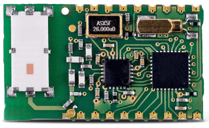
Revision history

 Manual
           Notes                                                              Date
 version

 1.0          • Initial version                                               October 2019

 1.1          • Added Proteus-III                                             February 2020

              • Update Tarvos-I to Tarvos-III chapter due to Tarvos-III
                firmware update affecting transparent mode

              • Update Tarvos-II to Tarvos-III chapter due to Tarvos-III
                firmware update affecting transparent mode
 1.2                                                                          January 2021
              • Update Thebe-I to Thebe-II chapter due to Thebe-II firmware
                update affecting transparent mode

              • Improvements for Proteus chapters

              • Added chapters Telesto-III to Themisto-I and Tarvos-III
 1.3            to Thebe-II                                                   January 2021

 1.4          • Added chapter Thadeus to Tarvos-III                           July 2021

              • Added chapters Tarvos/AMB8420 to Tarvos-III
 1.5            and References                                                September 2021

ANR016 Radio Module Migration Guide version 1.5                     © September 2021
www.we-online.com/wireless-connectivity                                              1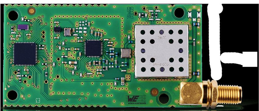
Abbreviations and abstract

 Abbreviation   Name                 Description
                                     Radio packet send back to the transmitter to
 ACK            Acknowledgement
                                     acknowledge the reception of data.
                                     The ability to receive the wanted radio signal with
                Blocking
                                     close radio noise.
 LRM            Long range mode      Special radio profile for large transmission ranges.
                Payload              The intended message in a frame / package.
 RF             Radio frequency      Describes wireless transmission.
 SRD            Short Range Device   Unlicensed frequency bands.

ANR016 Radio Module Migration Guide version 1.5                      © September 2021
www.we-online.com/wireless-connectivity                                                2
Contents
1 Introduction                                                                                                                                    6

2 Thadeus to Tarvos-III                                                                                                                            7
  2.1  Summary . . . . . . . . . . .      .   .   .   .   .   .   .   .   .   .   .   .   .   .   .   .   .   .   .   .   .   .   .   .   .   .    7
  2.2  Hardware adaption . . . . . .      .   .   .   .   .   .   .   .   .   .   .   .   .   .   .   .   .   .   .   .   .   .   .   .   .   .    8
        2.2.1 Foot print . . . . . . .    .   .   .   .   .   .   .   .   .   .   .   .   .   .   .   .   .   .   .   .   .   .   .   .   .   .    8
        2.2.2 Pinout . . . . . . . .      .   .   .   .   .   .   .   .   .   .   .   .   .   .   .   .   .   .   .   .   .   .   .   .   .   .    9
        2.2.3 Antenna . . . . . . .       .   .   .   .   .   .   .   .   .   .   .   .   .   .   .   .   .   .   .   .   .   .   .   .   .   .   10
  2.3  Host firmware adaption . . .       .   .   .   .   .   .   .   .   .   .   .   .   .   .   .   .   .   .   .   .   .   .   .   .   .   .   10
        2.3.1 Command Mode . .            .   .   .   .   .   .   .   .   .   .   .   .   .   .   .   .   .   .   .   .   .   .   .   .   .   .   10
        2.3.2 UART interface . . .        .   .   .   .   .   .   .   .   .   .   .   .   .   .   .   .   .   .   .   .   .   .   .   .   .   .   10
        2.3.3 Radio interface . . .       .   .   .   .   .   .   .   .   .   .   .   .   .   .   .   .   .   .   .   .   .   .   .   .   .   .   11
        2.3.4 Power saving modes          .   .   .   .   .   .   .   .   .   .   .   .   .   .   .   .   .   .   .   .   .   .   .   .   .   .   11
        2.3.5 Boot mode . . . . . .       .   .   .   .   .   .   .   .   .   .   .   .   .   .   .   .   .   .   .   .   .   .   .   .   .   .   11
        2.3.6 Timings . . . . . . .       .   .   .   .   .   .   .   .   .   .   .   .   .   .   .   .   .   .   .   .   .   .   .   .   .   .   11
        2.3.7 Transparent mode . .        .   .   .   .   .   .   .   .   .   .   .   .   .   .   .   .   .   .   .   .   .   .   .   .   .   .   11

3 Tarvos/AMB8420 to Tarvos-III                                                                                                                    12
  3.1   Summary . . . . . . . . . . . . . . . . . . . . . . . . . . .                                     .   .   .   .   .   .   .   .   .   .   12
  3.2   Hardware adaption . . . . . . . . . . . . . . . . . . . . . .                                     .   .   .   .   .   .   .   .   .   .   13
         3.2.1 Foot print . . . . . . . . . . . . . . . . . . . . . . .                                   .   .   .   .   .   .   .   .   .   .   13
         3.2.2 Pinout . . . . . . . . . . . . . . . . . . . . . . . .                                     .   .   .   .   .   .   .   .   .   .   14
         3.2.3 Antenna . . . . . . . . . . . . . . . . . . . . . . .                                      .   .   .   .   .   .   .   .   .   .   14
  3.3   Host firmware adaption . . . . . . . . . . . . . . . . . . .                                      .   .   .   .   .   .   .   .   .   .   14
         3.3.1 Command Mode . . . . . . . . . . . . . . . . . .                                           .   .   .   .   .   .   .   .   .   .   14
         3.3.2 UART interface . . . . . . . . . . . . . . . . . . .                                       .   .   .   .   .   .   .   .   .   .   14
         3.3.3 Radio interface . . . . . . . . . . . . . . . . . . .                                      .   .   .   .   .   .   .   .   .   .   14
         3.3.4 Power saving modes . . . . . . . . . . . . . . . .                                         .   .   .   .   .   .   .   .   .   .   15
         3.3.5 Boot mode . . . . . . . . . . . . . . . . . . . . . .                                      .   .   .   .   .   .   .   .   .   .   15
         3.3.6 Timings . . . . . . . . . . . . . . . . . . . . . . .                                      .   .   .   .   .   .   .   .   .   .   16
         3.3.7 Switch between transparent and command mode                                                .   .   .   .   .   .   .   .   .   .   16

4 Tarvos-I to Tarvos-III                                                                                                                          17
  4.1   Summary . . . . . . . . . . . . . . . . .                 .   .   .   .   .   .   .   .   .   .   .   .   .   .   .   .   .   .   .   .   17
  4.2   Hardware adaption . . . . . . . . . . . .                 .   .   .   .   .   .   .   .   .   .   .   .   .   .   .   .   .   .   .   .   18
         4.2.1 Foot print . . . . . . . . . . . . .               .   .   .   .   .   .   .   .   .   .   .   .   .   .   .   .   .   .   .   .   18
         4.2.2 Pinout . . . . . . . . . . . . . .                 .   .   .   .   .   .   .   .   .   .   .   .   .   .   .   .   .   .   .   .   19
         4.2.3 Antenna . . . . . . . . . . . . .                  .   .   .   .   .   .   .   .   .   .   .   .   .   .   .   .   .   .   .   .   20
  4.3   Host firmware adaption . . . . . . . . .                  .   .   .   .   .   .   .   .   .   .   .   .   .   .   .   .   .   .   .   .   20
         4.3.1 Command Mode . . . . . . . .                       .   .   .   .   .   .   .   .   .   .   .   .   .   .   .   .   .   .   .   .   20
         4.3.2 UART interface . . . . . . . . .                   .   .   .   .   .   .   .   .   .   .   .   .   .   .   .   .   .   .   .   .   20
         4.3.3 Radio interface . . . . . . . . .                  .   .   .   .   .   .   .   .   .   .   .   .   .   .   .   .   .   .   .   .   21
         4.3.3.1    Radio compatibility settings                  .   .   .   .   .   .   .   .   .   .   .   .   .   .   .   .   .   .   .   .   21
         4.3.4 Power saving modes . . . . . .                     .   .   .   .   .   .   .   .   .   .   .   .   .   .   .   .   .   .   .   .   22
         4.3.5 Boot mode . . . . . . . . . . . .                  .   .   .   .   .   .   .   .   .   .   .   .   .   .   .   .   .   .   .   .   22
         4.3.6 Timings . . . . . . . . . . . . .                  .   .   .   .   .   .   .   .   .   .   .   .   .   .   .   .   .   .   .   .   22
         4.3.7 Transparent mode . . . . . . . .                   .   .   .   .   .   .   .   .   .   .   .   .   .   .   .   .   .   .   .   .   22

ANR016 Radio Module Migration Guide version 1.5                                                                   © September 2021
www.we-online.com/wireless-connectivity                                                                                                            3
5 Tarvos-II to Tarvos-III                                                                                                                                23
  5.1   Summary . . . . . . . . . . . . . . . . .                        .   .   .   .   .   .   .   .   .   .   .   .   .   .   .   .   .   .   .   .   23
  5.2   Hardware adaption . . . . . . . . . . . .                        .   .   .   .   .   .   .   .   .   .   .   .   .   .   .   .   .   .   .   .   24
         5.2.1 Foot print . . . . . . . . . . . . .                      .   .   .   .   .   .   .   .   .   .   .   .   .   .   .   .   .   .   .   .   24
         5.2.2 Pinout . . . . . . . . . . . . . .                        .   .   .   .   .   .   .   .   .   .   .   .   .   .   .   .   .   .   .   .   24
         5.2.3 Antenna . . . . . . . . . . . . .                         .   .   .   .   .   .   .   .   .   .   .   .   .   .   .   .   .   .   .   .   26
  5.3   Host firmware adaption . . . . . . . . .                         .   .   .   .   .   .   .   .   .   .   .   .   .   .   .   .   .   .   .   .   26
         5.3.1 Command Mode . . . . . . . .                              .   .   .   .   .   .   .   .   .   .   .   .   .   .   .   .   .   .   .   .   26
         5.3.2 UART interface . . . . . . . . .                          .   .   .   .   .   .   .   .   .   .   .   .   .   .   .   .   .   .   .   .   26
         5.3.3 Radio interface . . . . . . . . .                         .   .   .   .   .   .   .   .   .   .   .   .   .   .   .   .   .   .   .   .   26
         5.3.3.1     Radio compatibility settings                        .   .   .   .   .   .   .   .   .   .   .   .   .   .   .   .   .   .   .   .   27
         5.3.4 Power saving modes . . . . . .                            .   .   .   .   .   .   .   .   .   .   .   .   .   .   .   .   .   .   .   .   27
         5.3.5 Boot mode . . . . . . . . . . . .                         .   .   .   .   .   .   .   .   .   .   .   .   .   .   .   .   .   .   .   .   27
         5.3.6 Timings . . . . . . . . . . . . .                         .   .   .   .   .   .   .   .   .   .   .   .   .   .   .   .   .   .   .   .   27
         5.3.7 Transparent mode . . . . . . . .                          .   .   .   .   .   .   .   .   .   .   .   .   .   .   .   .   .   .   .   .   28

6 Tarvos-III to Thebe-II                                                                                                                                 29
  6.1   Summary . . . . . . . .      .   .   .   .   .   .   .   .   .   .   .   .   .   .   .   .   .   .   .   .   .   .   .   .   .   .   .   .   .   29
  6.2   Hardware adaption . . .      .   .   .   .   .   .   .   .   .   .   .   .   .   .   .   .   .   .   .   .   .   .   .   .   .   .   .   .   .   29
         6.2.1 Foot print . . . .    .   .   .   .   .   .   .   .   .   .   .   .   .   .   .   .   .   .   .   .   .   .   .   .   .   .   .   .   .   29
         6.2.2 Pinout . . . . .      .   .   .   .   .   .   .   .   .   .   .   .   .   .   .   .   .   .   .   .   .   .   .   .   .   .   .   .   .   29
         6.2.3 Power supply .        .   .   .   .   .   .   .   .   .   .   .   .   .   .   .   .   .   .   .   .   .   .   .   .   .   .   .   .   .   30
  6.3   Host firmware adaption       .   .   .   .   .   .   .   .   .   .   .   .   .   .   .   .   .   .   .   .   .   .   .   .   .   .   .   .   .   30
         6.3.1 Radio interface       .   .   .   .   .   .   .   .   .   .   .   .   .   .   .   .   .   .   .   .   .   .   .   .   .   .   .   .   .   30

7 Thebe-I to Thebe-II                                                                                                                                    32
  7.1  Summary . . . . . . . . . . .             .   .   .   .   .   .   .   .   .   .   .   .   .   .   .   .   .   .   .   .   .   .   .   .   .   .   32
  7.2  Hardware adaption . . . . . .             .   .   .   .   .   .   .   .   .   .   .   .   .   .   .   .   .   .   .   .   .   .   .   .   .   .   32
         7.2.1 Foot print . . . . . . .          .   .   .   .   .   .   .   .   .   .   .   .   .   .   .   .   .   .   .   .   .   .   .   .   .   .   32
         7.2.2 Pinout . . . . . . . .            .   .   .   .   .   .   .   .   .   .   .   .   .   .   .   .   .   .   .   .   .   .   .   .   .   .   32
         7.2.3 Antenna . . . . . . .             .   .   .   .   .   .   .   .   .   .   .   .   .   .   .   .   .   .   .   .   .   .   .   .   .   .   33
  7.3  Host firmware adaption . . .              .   .   .   .   .   .   .   .   .   .   .   .   .   .   .   .   .   .   .   .   .   .   .   .   .   .   33
         7.3.1 UART interface . . .              .   .   .   .   .   .   .   .   .   .   .   .   .   .   .   .   .   .   .   .   .   .   .   .   .   .   33
         7.3.2 Radio interface . . .             .   .   .   .   .   .   .   .   .   .   .   .   .   .   .   .   .   .   .   .   .   .   .   .   .   .   33
         7.3.3 Power saving modes                .   .   .   .   .   .   .   .   .   .   .   .   .   .   .   .   .   .   .   .   .   .   .   .   .   .   34
         7.3.4 Boot mode . . . . . .             .   .   .   .   .   .   .   .   .   .   .   .   .   .   .   .   .   .   .   .   .   .   .   .   .   .   34
         7.3.5 Transparent mode . .              .   .   .   .   .   .   .   .   .   .   .   .   .   .   .   .   .   .   .   .   .   .   .   .   .   .   34

8 Telesto-III to Themisto-I                                                                                                                              35
  8.1   Summary . . . . . . . .      .   .   .   .   .   .   .   .   .   .   .   .   .   .   .   .   .   .   .   .   .   .   .   .   .   .   .   .   .   35
  8.2   Hardware adaption . . .      .   .   .   .   .   .   .   .   .   .   .   .   .   .   .   .   .   .   .   .   .   .   .   .   .   .   .   .   .   35
         8.2.1 Foot print . . . .    .   .   .   .   .   .   .   .   .   .   .   .   .   .   .   .   .   .   .   .   .   .   .   .   .   .   .   .   .   35
         8.2.2 Pinout . . . . .      .   .   .   .   .   .   .   .   .   .   .   .   .   .   .   .   .   .   .   .   .   .   .   .   .   .   .   .   .   35
         8.2.3 Power supply .        .   .   .   .   .   .   .   .   .   .   .   .   .   .   .   .   .   .   .   .   .   .   .   .   .   .   .   .   .   36
  8.3   Host firmware adaption       .   .   .   .   .   .   .   .   .   .   .   .   .   .   .   .   .   .   .   .   .   .   .   .   .   .   .   .   .   36
         8.3.1 Radio interface       .   .   .   .   .   .   .   .   .   .   .   .   .   .   .   .   .   .   .   .   .   .   .   .   .   .   .   .   .   36

9 Metis-I to Metis-II                                                                                                                                    37
  9.1   Summary . . . . . . . . . . . . . . . . . . . . . . . . . . . . . . . . . . . . .                                                                37

10 Proteus-I to Proteus-II                                                                                                                               38
   10.1 Summary . . . . . . . . . . . . . . . . . . . . . . . . . . . . . . . . . . . . .                                                                38

ANR016 Radio Module Migration Guide version 1.5                                                                          © September 2021
www.we-online.com/wireless-connectivity                                                                                                                   4
11 Proteus-II to Proteus-III                                                                                                                              39
   11.1 Summary . . . . . . . .       .   .   .   .   .   .   .   .   .   .   .   .   .   .   .   .   .   .   .   .   .   .   .   .   .   .   .   .   .   39
   11.2 Hardware adaption . . .       .   .   .   .   .   .   .   .   .   .   .   .   .   .   .   .   .   .   .   .   .   .   .   .   .   .   .   .   .   40
          11.2.1 Foot print . . . .   .   .   .   .   .   .   .   .   .   .   .   .   .   .   .   .   .   .   .   .   .   .   .   .   .   .   .   .   .   40
          11.2.2 Pinout . . . . .     .   .   .   .   .   .   .   .   .   .   .   .   .   .   .   .   .   .   .   .   .   .   .   .   .   .   .   .   .   40
          11.2.3 Antenna . . . .      .   .   .   .   .   .   .   .   .   .   .   .   .   .   .   .   .   .   .   .   .   .   .   .   .   .   .   .   .   42
   11.3 Host firmware adaption        .   .   .   .   .   .   .   .   .   .   .   .   .   .   .   .   .   .   .   .   .   .   .   .   .   .   .   .   .   42

12 AMB2520 to Thalassa                                                                                                                                    43
   12.1 Summary . . . . . . . .       .   .   .   .   .   .   .   .   .   .   .   .   .   .   .   .   .   .   .   .   .   .   .   .   .   .   .   .   .   43
   12.2 Hardware adaption . . .       .   .   .   .   .   .   .   .   .   .   .   .   .   .   .   .   .   .   .   .   .   .   .   .   .   .   .   .   .   43
         12.2.1 Foot print . . . .    .   .   .   .   .   .   .   .   .   .   .   .   .   .   .   .   .   .   .   .   .   .   .   .   .   .   .   .   .   43
         12.2.2 Pinout . . . . .      .   .   .   .   .   .   .   .   .   .   .   .   .   .   .   .   .   .   .   .   .   .   .   .   .   .   .   .   .   44
         12.2.3 Antenna . . . .       .   .   .   .   .   .   .   .   .   .   .   .   .   .   .   .   .   .   .   .   .   .   .   .   .   .   .   .   .   44
   12.3 Host firmware adaption        .   .   .   .   .   .   .   .   .   .   .   .   .   .   .   .   .   .   .   .   .   .   .   .   .   .   .   .   .   44

13 References                                                                                                                                             45

14 Important notes                                                                                                                                        46
   14.1 General customer responsibility . . . . . . . .                               . . . . . . . . . . . . . . . . .                                   46
   14.2 Customer responsibility related to specific, in                               particular safety-relevant ap-
         plications . . . . . . . . . . . . . . . . . . . .                           . . . . . . . . . . . . . . . . .                                   46
   14.3 Best care and attention . . . . . . . . . . . .                               . . . . . . . . . . . . . . . . .                                   46
   14.4 Customer support for product specifications .                                 . . . . . . . . . . . . . . . . .                                   46
   14.5 Product improvements . . . . . . . . . . . . .                                . . . . . . . . . . . . . . . . .                                   47
   14.6 Product life cycle . . . . . . . . . . . . . . . .                            . . . . . . . . . . . . . . . . .                                   47
   14.7 Property rights . . . . . . . . . . . . . . . . .                             . . . . . . . . . . . . . . . . .                                   47
   14.8 General terms and conditions . . . . . . . . .                                . . . . . . . . . . . . . . . . .                                   47

15 Legal notice                                                                                                                                           48
   15.1 Exclusion of liability . . . . . . . . .              .   .   .   .   .   .   .   .   .   .   .   .   .   .   .   .   .   .   .   .   .   .   .   48
   15.2 Suitability in customer applications                  .   .   .   .   .   .   .   .   .   .   .   .   .   .   .   .   .   .   .   .   .   .   .   48
   15.3 Trademarks . . . . . . . . . . . . .                  .   .   .   .   .   .   .   .   .   .   .   .   .   .   .   .   .   .   .   .   .   .   .   48
   15.4 Usage restriction . . . . . . . . . .                 .   .   .   .   .   .   .   .   .   .   .   .   .   .   .   .   .   .   .   .   .   .   .   48

16 License terms                                                                                                                                          50
   16.1 Limited license . . . . . . . .           .   .   .   .   .   .   .   .   .   .   .   .   .   .   .   .   .   .   .   .   .   .   .   .   .   .   50
   16.2 Usage and obligations . . . .             .   .   .   .   .   .   .   .   .   .   .   .   .   .   .   .   .   .   .   .   .   .   .   .   .   .   50
   16.3 Ownership . . . . . . . . . . .           .   .   .   .   .   .   .   .   .   .   .   .   .   .   .   .   .   .   .   .   .   .   .   .   .   .   51
   16.4 Firmware update(s) . . . . . .            .   .   .   .   .   .   .   .   .   .   .   .   .   .   .   .   .   .   .   .   .   .   .   .   .   .   51
   16.5 Disclaimer of warranty . . . .            .   .   .   .   .   .   .   .   .   .   .   .   .   .   .   .   .   .   .   .   .   .   .   .   .   .   51
   16.6 Limitation of liability . . . . . .       .   .   .   .   .   .   .   .   .   .   .   .   .   .   .   .   .   .   .   .   .   .   .   .   .   .   51
   16.7 Applicable law and jurisdiction           .   .   .   .   .   .   .   .   .   .   .   .   .   .   .   .   .   .   .   .   .   .   .   .   .   .   52
   16.8 Severability clause . . . . . .           .   .   .   .   .   .   .   .   .   .   .   .   .   .   .   .   .   .   .   .   .   .   .   .   .   .   52
   16.9 Miscellaneous . . . . . . . . .           .   .   .   .   .   .   .   .   .   .   .   .   .   .   .   .   .   .   .   .   .   .   .   .   .   .   52

ANR016 Radio Module Migration Guide version 1.5                                                                           © September 2021
www.we-online.com/wireless-connectivity                                                                                                                    5
1 Introduction
The radio frequency spectrum is regulated by designated regulatory authorities that define
how specific spectrum bands can be used. As each frequency band has its strength, Würth
Elektronik eiSos provides for each frequency band proprietary radio modules, which allow
energy efficient and fast data transmission.

With the evolution of radio chips, new proprietary radio modules have been developed, that
are more energy efficient during data transmission and reception. Furthermore new coding
and modulation techniques have been added, that allow higher transmission ranges (long
range mode) and/or higher data rates.

Due to this natural evolution, when redesigning a device that is already using a proprietary
radio module, it is recommended to use the latest member of the corresponding radio mod-
ule family.

This application note describes the key factors to be considered, when replacing a pro-
prietary Würth Elektronik eiSos radio module with its successor from the same family.

              Due to changes in hardware platform and firmware when replacing a radio
              module with its successor, the end device’s radio certification becomes void.
              A new radio certification or declaration needs to be acquired by performing
              actions according to the local statutory requirements at the location of deploy-
              ment.

              If a switch from 868 MHz to 915 MHz is desired to serve also the North Amer-
              ican market, the application note ANR015 "FROM 868 MHZ TO 915 MHZ"
              describes the necessary steps to be performed.

ANR016 Radio Module Migration Guide version 1.5                           © September 2021
www.we-online.com/wireless-connectivity                                                     6
2 Thadeus to Tarvos-III
The Thadeus is a 434 MHz proprietary radio module. The Tarvos-III is a 868-MHz radio
module of a later generation, that reduces the power consumption, improves the blocking
capabilities and provides new modulation techniques to boost the transmission range.

                               Figure 1: Thadeus to Tarvos-III

2.1 Summary
In comparison to the Thadeus, the Tarvos-III has 4 additional pins. Since the size and the
remaining footprint of the two modules are the same, the Thadeus can be replaced by the
Tarvos-III, if no underlying non-insulated copper area touches the 4 new pins of the Tarvos-
III.
Besides of this, a few pin functions changed, such that the sleep mode for example has to be
triggered in a different way on the Tarvos-III. Due to this, and due to new firmware functions
the host firmware must be adapted to communicate with the Tarvos-III.
Radio compatibility of both modules is not given as both operate in different frequency band-
s. Nevertheless, the radio features like addressing or acknowledgments remain the same.

ANR016 Radio Module Migration Guide version 1.5                           © September 2021
www.we-online.com/wireless-connectivity                                                     7
2.2 Hardware adaption
2.2.1 Foot print
Both Thadeus and Tarvos-III have the same dimensions of 17×27×4 mm with the pins locat-
ed at the same positions. The only change in the footprint is the presence of 4 additional
pins (i1-i4) of the JTAG interface on the Tarvos-III.
If a design has been made for Thadeus, the footprint matches the Tarvos-III, if no underlying
non-insulated copper area touches the JTAG pins i1-i4 of the Tarvos-III.

              In addition to the radio signal to an external antenna on pin 1, the Tarvos-III
              offers an alternative option to use the on-board PCB antenna. The order code
              for Tarvos-III with external antenna is 260901118100x. The integrated PCB
              antenna with reduced efficiency is available using order code 260901108100x.

                                Figure 2: Universal footprint

ANR016 Radio Module Migration Guide version 1.5                           © September 2021
www.we-online.com/wireless-connectivity                                                    8
2.2.2 Pinout
Although the Thadeus and Tarvos-III share the same footprint, some of the pin functions
differ on the new hardware platform. The main pin functions such as power supply and
UART use the same footprint pin on both modules:

  Pin
           Thadeus        Tarvos-III       Comment
  No.
   1           ANT           ANT           Antenna pin connection
   2           GND           GND           Ground
   3           VCC           VCC           Supply voltage
   4        UTXD            UTXD           UART TX
   5        URXD            URXD           UART RX
   6           /RTS          /RTS          UART /RTS
   9     RESERVED        RESERVED
  10     RESERVED        RESERVED
  16     RESERVED        RESERVED
  17     RESERVED        RESERVED
  18     RESERVED        RESERVED
  19       /RESET          /RESET          Reset pin
  20       /TX_IND         /TX_IND         Pin indicating when a radio packet is transmitted
  21       /RX_IND         /RX_IND         Pin indicating when a radio packet is received
  22     RESERVED        RESERVED
  23           GND           GND           Ground

            Table 1: Pins with same functions on both, Thadeus and Tarvos-III

But pins with special functions changed:

ANR016 Radio Module Migration Guide version 1.5                            © September 2021
www.we-online.com/wireless-connectivity                                                        9
Pin
Thadeus Tarvos-III Comment
No.
7 /CTS RESERVED /CTS function no longer supported.
8 DATA_IND RESERVED DATA_IND function no longer supported.
11 DATA_REQ RESERVED DATA_REQ function no longer supported.
The BOOT pin is used on the Tarvos-III to set the
12 RESERVED BOOT module into boot mode, where the module’s firmware
can be updated using the ACC tool.
Sleep function by pin no longer supported, as the
13 SLEEP RESERVED
Tarvos-III enters the sleep modes via command.
Pin function changed. The WAKE-UP pin is used to
14 TRX_DISABLE WAKE-UP
wake-up the module from sleep mode.
The MODE_1 pin is used on the Tarvos-III to
determine the operating mode during boot. In
15 /CONFIG MODE_1 contrast to the Thadeus, switching between
transparent mode and command mode is not
possible during runtime by using the MODE_1 pin.
Table 2: Pins of the Thadeus and Tarvos-III that have different functions
2.2.3 Antenna
The Tarvos-III is available in two hardware variants. The first variant provides the radio signal
at the ANT pin, the same as Thadeus. Using this variant an external antenna matched to
50 Ω can be connected at this pin.
The second variant of the Tarvos-III offers an internal PCB antenna. Using this variant the
ANT pin has no function and can be left open. No external antenna has to be connected.
2.3 Host firmware adaption
2.3.1 Command Mode
If you are not already using command mode we recommend to switch over to using com-
mand mode whenever your application can be adopted.
2.3.2 UART interface
The Thadeus uses 9600 Baud 8n1 and Tarvos-III uses 115200 Baud 8n1 by default. The
Thadeus provides the command and transparent mode on the UART (transparent mode by
default). The Tarvos-III provides the command mode and, using firmware version 3.0.0 or
higher, the transparent mode (command mode by default).
The command interface on the UART uses of the same command structure. The UART
command numbers itself and range of parameter values for a specific command may differ.
Thus the command interface must be updated in the host controller. The source codes of
the command interface for host integration are available in the Wireless Connectivity SDK
on GitHub [1] [2].
ANR016 Radio Module Migration Guide version 1.5 © September 2021
www.we-online.com/wireless-connectivity 102.3.3 Radio interface The radio interfaces of the Tarvos-III and Thadeus are not compatible as different radio pro- files and radio channels (frequencies) are used. Nevertheless, both radio modules support radio features like addressing and acknowlegdement. 2.3.4 Power saving modes As the pins SLEEP and TRX_DISABLE of the Thadeus are no more available on the Tarvos- III, the low power modes are handled in a different way. The Tarvos-III does not enable the possibility to switch off the radio exclusively by a pin, but allows to enter into two different sleep modes via UART command. The Tarvos-III can be woken up again from any sleep mode using the WAKE-UP pin, which is at the location of the Thadeus TRX_DISABLE pin. 2.3.5 Boot mode The Tarvos-III needs to be set to boot mode, if a firmware update is performed. To switch the boot mode on, the BOOT pin has to be handled by host controller. The firmware update uses the UART interface at the dedicated module UART pins. Both, Thadeus and Tarvos-III can be connected to the ACC PC tool to perform changes in user settings and a firmware update. Please refer to the product specific details for the firmware update. 2.3.6 Timings Due to change of the underlying hardware, especially the CPU and radio IC, as well as the use of an RTOS (real time operating system) in the Tarvos-III, most of the timing parameters have slightly changed. Some were decreased, but others increased. Due to the CPU change and the RTOS the UART RX of the module is now using a shift register of 32 bit instead of 8 bit, which will introduce (worst case) a latency of up to 3 ad- ditional byte durations (depending on the selected UART data rate) to each received UART message (command or transparent). The host-application needs to take this changed timings into account to be able to use the Tarvos-III as replacement. 2.3.7 Transparent mode Tarvos-III firmware 3.0.0 or newer is required for transparent mode support. ANR016 Radio Module Migration Guide version 1.5 © September 2021 www.we-online.com/wireless-connectivity 11
3 Tarvos/AMB8420 to Tarvos-III
The Tarvos series is a family of 868 MHz proprietary radio modules. The Tarvos (formerly
known as AMB8420) has been succeeded by the Tarvos-III, that reduces the power con-
sumption and provides a cleaner frequency spectrum, improved blocking capabilities and
new modulation techniques to boost the transmission range.

                               Figure 3: Tarvos to Tarvos-III

3.1 Summary
In comparison to the Tarvos, the Tarvos-III has a slightly different size and footprint. Both
radio modules are available with internal antenna and as a variant with the radio signal on
the module pad for external antenna connection.
A few pin and software functions changed, such that the host firmware must be adapted to
communicate with the Tarvos-III.
Radio compatibility of both modules is given under certain conditions.

              If the host cannot be adopted it may not be possible to perform migration to a
              more recent product.

ANR016 Radio Module Migration Guide version 1.5                           © September 2021
www.we-online.com/wireless-connectivity                                                   12
RESERVED
23
GND GND
VCC RESERVED
UTXD TX_IND
URXD RX_IND
/RTS /RESET
RESERVED RESERVED
RESERVED RESERVED
RESERVED RESERVED
RESERVED MODE_1
RESERVED WAKE-UP
i4
i1
12
13
BOOT RESERVED
a) Tarvos
TEST
TEST
TEST
TEST
b) Tarvos-III
Figure 4: Pinout
3.2 Hardware adaption
3.2.1 Foot print
Both Tarvos and Tarvos-III have similar but not identical dimensions. Where the Tarvos
has the size of 16×27.5 mm, the Tarvos-III is 17×27 mm. In addition to that Tarvos-III has
additional pins and new pad locations.
ANR016 Radio Module Migration Guide version 1.5 © September 2021
www.we-online.com/wireless-connectivity 133.2.2 Pinout The pinout of both modules is very similar. The main functions such as power supply, reset and UART share the same pins, but special pin functions have been updated. In detail, the DATA_REQUEST , DATA_INDICATION, TRX_DISABLE and SLEEP pins have been replaced by the WAKE_UP, TX_IND and RX_IND pins. This has the effect that it’s not longer possible to trigger the radio transmission and sleep mode via pin. Both, the data transmission as well as the sleep mode have to be triggered by UART commands. The wake-up from sleep mode is still possible via the WAKE_UP pin. The switch between transparent and command mode is now done via the MODE_1 pin, that replaces the CONFIG pin and defines the operation mode right after the start-up of the module. Last but not least a BOOT pin has been added, that allows the Tarvos-III to enter the boot mode for firmware updates via the UART. 3.2.3 Antenna The Tarvos and the Tarvos-III are available in two hardware variants. The first variant pro- vides the radio signal at the ANT pin. Using this variant an external antenna matched to 50 Ω can be connected at this pin. The second variant offers an internal PCB antenna. Using this variant the ANT pin has no function and can be left open. No external antenna has to be connected. 3.3 Host firmware adaption 3.3.1 Command Mode If you are not already using command mode, we recommend to switch over to using com- mand mode whenever your application can be adopted. 3.3.2 UART interface The Tarvos uses 9600 Baud 8n1 and Tarvos-III uses 115200 Baud 8n1 by default. The Tarvos provides the command and transparent mode on the UART (transparent mode by default). The Tarvos-III provides the command mode and, using firmware version 3.0.0 or higher, the transparent mode (command mode by default). The command interface on the UART uses of the same command structure. The UART command numbers itself and range of parameter values for a specific command may differ. Thus the command interface must be updated in the host controller. The source codes of the command interface for host integration are available in the Wireless Connectivity SDK on GitHub [1] [2]. 3.3.3 Radio interface The Tarvos-III is supporting more radio channels and radio profiles than available on Tarvos. Both radio modules support the 38.4 kbps and 100 kbps radio profile as well as radio chan- nels 102 - 110. If one of these radio channels and radio profiles is used, the Tarvos and Tarvos-III are radio compatible provided that acknowledgements are disabled. The radio timing behavior must be adapted using the respective user settings to allow the communica- tion between Tarvos and Tarvos-III, in case acknowlegdements are enabled. ANR016 Radio Module Migration Guide version 1.5 © September 2021 www.we-online.com/wireless-connectivity 14
Using these radio settings, a higher radio range can be achieved compared to Tarvos owing
to the higher default transmission power of Tarvos-III.
The new radio profiles of the Tarvos-III are incompatible to the previous Tarvos generations,
but offer various advantages. The radio profiles 3 and 4 allow a higher transmission range,
where radio profile 5 provides a fast data transmission due to the increased data-rate.

            Radio         Data rate (gross)         Max payload
                                                                           Radio channels
            profile            [kbps]                size [Byte]
               -                  4.8                   1282                 102 - 110
               -                  10                    1282                 102 - 110
               -                 38.4                   1282                 103 - 109
                                                              2
               -                 76.8                   128                  104 - 108
               -                  100                   1282                 105 - 107

                                 Table 3: Radio profiles of the Tarvos

            Radio         Data rate (gross)         Max payload
                                                                           Radio channels
            profile            [kbps]                size [Byte]
               0                 38.4                    128                  1 - 139
               2                  100                    128                  1 - 139
           3 (LRM)      10 (=0.625 kbps net)             48                   1 - 139
           4 (LRM)        20 (=2.5 kbps net)             64                   1 - 139
               5                  400                    224                  1 - 139

                               Table 4: Radio profiles of the Tarvos-III

3.3.4 Power saving modes
As the pins SLEEP and TRX_DISABLE of the Tarvos are no more available on the Tarvos-
III, the low power modes are handled in a different way. The Tarvos-III does not enable the
possibility to switch off the radio exclusively via pin, but allows to enter into two different
sleep modes via UART command. The Tarvos-III can be woken from any sleep mode using
the WAKE-UP pin, which is at the location of the Tarvos TRX_DISABLE pin.

3.3.5 Boot mode
The Tarvos-III needs to be set to boot mode, if a firmware update is performed. To switch
the boot mode on, the BOOT pin has to be handled by host controller. The firmware update
uses the UART interface at the dedicated module UART pins. Both, Tarvos and Tarvos-III
can be connected to the ACC PC tool to perform changes in user settings and a firmware
update. Please refer to the product specific details for the firmware update.

 2
     The maximum payload size depends on the selected address mode.

ANR016 Radio Module Migration Guide version 1.5                                  © September 2021
www.we-online.com/wireless-connectivity                                                        15
3.3.6 Timings
Due to change of the underlying hardware, especially the CPU and radio IC, as well as the
use of an RTOS (real time operating system) in the Tarvos-III, most of the timing parameters
have slightly changed. Some were decreased, but others increased.
Due to the CPU change and the RTOS the UART RX of the module is now using a shift
register of 32 bit instead of 8 bit, which will introduce (worst case) a latency of up to 3 ad-
ditional byte durations (depending on the selected UART data rate) to each received UART
message (command or transparent).
The host-application needs to take this changed timings into account to be able to use the
Tarvos-III as replacement.
3.3.7 Switch between transparent and command mode
Tarvos-III firmware 3.0.0 or newer is required for transparent mode support.
The CONFIG pin has been replaced by the MODE_1 pin, that defines the operation mode
after module start-up by the pin level. During operation the mode can be switched by UART
commands.
ANR016 Radio Module Migration Guide version 1.5 © September 2021
www.we-online.com/wireless-connectivity 164 Tarvos-I to Tarvos-III
The Tarvos series is a family of 868 MHz proprietary radio modules. The Tarvos-I has
been succeeded by the Tarvos-II (chapter 5), that scores with lower sleep, transmission and
receptions currents, as well with a cleaner frequency spectrum. The Tarvos-II itself has
been succeeded by the Tarvos-III, that further reduces the power consumption and provides
new modulation techniques to boost the transmission range. Each generation also includes
improvements in the blocking capabilities.
Figure 5: Tarvos-I to Tarvos-III
4.1 Summary
In comparison to the Tarvos-I, the Tarvos-III has 4 additional pins. Since the size and the
remaining footprint of the two modules are the same, the Tarvos-I can be replaced by the
Tarvos-III, if no underlying non-insulated copper area touches the 4 new pins of the Tarvos-
III.
Besides of this, a few pin functions changed, such that the sleep mode for example has to be
triggered in a different way on the Tarvos-III. Due to this, and due to new firmware functions
the host firmware must be adapted to communicate with the Tarvos-III.
Radio compatibility of both modules is given in most operation modes.
If the host cannot be adopted it may not be possible to perform migration to a
more recent product.
ANR016 Radio Module Migration Guide version 1.5 © September 2021
www.we-online.com/wireless-connectivity 174.2 Hardware adaption
4.2.1 Foot print
Both Tarvos-I and Tarvos-III have the same dimensions of 17×27×4 mm with the pins located
at the same positions. The only change in the footprint is the presence of 4 additional
pins (i1-i4) of the JTAG interface on the Tarvos-III.
If a design has been made for Tarvos-I, the footprint matches the Tarvos-III, if no underlying
non-insulated copper area touches the JTAG pins i1-i4 of the Tarvos-III.
In addition to the radio signal to an external antenna on pin 1, the Tarvos-
III offers an alternative option to use the on-board PCB antenna. In order to
ensure a comparable radio performance to Tarvos-I, it is recommended to use
the variant with antenna pin to connect to an external antenna. The order code
for Tarvos-III with external antenna is 260901118100x. The integrated PCB
antenna with reduced efficiency is available using order code 260901108100x.
Figure 6: Universal footprint
ANR016 Radio Module Migration Guide version 1.5 © September 2021
www.we-online.com/wireless-connectivity 184.2.2 Pinout
Although the Tarvos-I and Tarvos-III share the same footprint, some of the pin functions differ
on the new hardware platform. The main pin functions such as power supply and UART use
the same footprint pin on both modules:
Pin
Tarvos-I Tarvos-III Comment
No.
1 ANT ANT Antenna pin connection
2 GND GND Ground
3 VCC VCC Supply voltage
4 UTXD UTXD UART TX
5 URXD URXD UART RX
6 /RTS /RTS UART /RTS
9 RESERVED RESERVED
10 RESERVED RESERVED
16 RESERVED RESERVED
17 RESERVED RESERVED
18 RESERVED RESERVED
19 /RESET /RESET Reset pin
20 /TX_IND /TX_IND Pin indicating when a radio packet is transmitted
21 /RX_IND /RX_IND Pin indicating when a radio packet is received
22 RESERVED RESERVED
23 GND GND Ground
Table 5: Pins with same functions on both, Tarvos-I and Tarvos-III
But pins with special functions changed:
ANR016 Radio Module Migration Guide version 1.5 © September 2021
www.we-online.com/wireless-connectivity 19Pin
Tarvos-I Tarvos-III Comment
No.
7 /CTS RESERVED /CTS function no longer supported.
8 DATA_IND RESERVED DATA_IND function no longer supported.
11 DATA_REQ RESERVED DATA_REQ function no longer supported.
The BOOT pin is used on the Tarvos-III to set the
12 RESERVED BOOT module into boot mode, where the module’s firmware
can be updated using the ACC tool.
Sleep function by pin no longer supported, as the
13 SLEEP RESERVED
Tarvos-III enters the sleep modes via command.
Pin function changed. The WAKE-UP pin is used to
14 TRX_DISABLE WAKE-UP
wake-up the module from sleep mode.
The MODE_1 pin is used on the Tarvos-III to
determine the operating mode during boot. In
15 /CONFIG MODE_1 contrast to the Tarvos-I, switching between
transparent mode and command mode is not
possible during runtime by using the MODE_1 pin.
Table 6: Pins of the Tarvos-I and Tarvos-III that have different functions
4.2.3 Antenna
The Tarvos-III is available in two hardware variants. The first variant provides the radio sig-
nal at the ANT pin, the same as Tarvos-I. Using this variant an external antenna matched to
50 Ω can be connected at this pin.
The second variant of the Tarvos-III offers an internal PCB antenna. Using this variant the
ANT pin has no function and can be left open. No external antenna has to be connected.
4.3 Host firmware adaption
4.3.1 Command Mode
If you are not already using command mode we recommend to switch over to using com-
mand mode whenever your application can be adopted.
4.3.2 UART interface
The Tarvos-I uses 9600 Baud 8n1 and Tarvos-III uses 115200 Baud 8n1 by default. The
Tarvos-I provides the command and transparent mode on the UART (transparent mode by
default). The Tarvos-III provides the command mode and, using firmware version 3.0.0 or
higher, the transparent mode (command mode by default).
The command interface on the UART uses of the same command structure. The UART
command numbers itself and range of parameter values for a specific command may differ.
Thus the command interface must be updated in the host controller. The source codes of
the command interface for host integration are available in the Wireless Connectivity SDK
on GitHub [1] [2].
ANR016 Radio Module Migration Guide version 1.5 © September 2021
www.we-online.com/wireless-connectivity 204.3.3 Radio interface
The radio interface of the Tarvos-III is compatible to that of Tarvos-I provided that the Tarvos-
III is configured to use the 38.4 kbps or the 100 kbps profile with the radio settings as de-
scribed in section 4.3.3.1. Using these radio settings, a higher radio range can be achieved
compared to Tarvos-I owing to the higher default transmission power of Tarvos-III. The new
radio profiles of the Tarvos-III are incompatible to the previous Tarvos generations, but offer
various advantages. The radio profiles 3 and 4 allow a higher transmission range, where
radio profile 5 provides a fast data transmission due to the increased data-rate.
Furthermore, all the radio channels, that are used by the Tarvos-I, are also supported by the
Tarvos-III.
Radio Data rate (gross) Max payload
Radio channels
profile [kbps] size [Byte]
- 4.8 1282 101 - 111
2
- 10 128 101 - 111
- 38.4 1282 101 - 111
- 76.8 1282 101 - 111
2
- 100 128 101 - 111
Table 7: Radio profiles of the Tarvos-I
Radio Data rate (gross) Max payload
Radio channels
profile [kbps] size [Byte]
0 38.4 128 1 - 139
2 100 128 1 - 139
3 (LRM) 10 (=0.625 kbps net) 48 1 - 139
4 (LRM) 20 (=2.5 kbps net) 64 1 - 139
5 400 224 1 - 139
Table 8: Radio profiles of the Tarvos-III
4.3.3.1 Radio compatibility settings
General: Tarvos-I firmware must be of version 2.1.0 or later.
Address mode: Tarvos-I supports only address mode 0 and 1.
Addresses: The Tarvos-III uses broadcast addresses by default, where as the Tarvos-I
uses 0 as default destination address and network ID.
Timings: The ACK timeouts must be adjusted to ensure interoperability between Tarvos-III
and Tarvos-I, when using acknowledgments.
2
The maximum payload size depends on the selected address mode.
ANR016 Radio Module Migration Guide version 1.5 © September 2021
www.we-online.com/wireless-connectivity 214.3.4 Power saving modes As the pins SLEEP and TRX_DISABLE of the Tarvos-I are no more available on the Tarvos- III, the low power modes are handled in a different way. The Tarvos-III does not enable the possibility to switch off the radio exclusively by a pin, but allows to enter into two different sleep modes via UART command. The Tarvos-III can be woken up again from any sleep mode using the WAKE-UP pin, which is at the location of the Tarvos-I TRX_DISABLE pin. 4.3.5 Boot mode The Tarvos-III needs to be set to boot mode, if a firmware update is performed. To switch the boot mode on, the BOOT pin has to be handled by host controller. The firmware update uses the UART interface at the dedicated module UART pins. Both, Tarvos-I and Tarvos-III can be connected to the ACC PC tool to perform changes in user settings and a firmware update. Please refer to the product specific details for the firmware update. 4.3.6 Timings Due to change of the underlying hardware, especially the CPU and radio IC, as well as the use of an RTOS (real time operating system) in the Tarvos-III, most of the timing parameters have slightly changed. Some were decreased, but others increased. Due to the CPU change and the RTOS the UART RX of the module is now using a shift register of 32 bit instead of 8 bit, which will introduce (worst case) a latency of up to 3 ad- ditional byte durations (depending on the selected UART data rate) to each received UART message (command or transparent). The host-application needs to take this changed timings into account to be able to use the Tarvos-III as replacement. 4.3.7 Transparent mode Tarvos-III firmware 3.0.0 or newer is required for transparent mode support. ANR016 Radio Module Migration Guide version 1.5 © September 2021 www.we-online.com/wireless-connectivity 22
5 Tarvos-II to Tarvos-III
The Tarvos series is a family of 868 MHz proprietary radio modules. The Tarvos-II has been
succeeded by the Tarvos-III, that reduces the power consumption, improves the blocking
capabilities and provides new modulation techniques to boost the transmission range.

                               Figure 7: Tarvos-II to Tarvos-III

5.1 Summary
In comparison to the Tarvos-II, the Tarvos-III has 4 additional pins. Since the size and the
remaining footprint of the two modules are the same, the Tarvos-II can be replaced by the
Tarvos-III, if no underlying non-insulated copper area touches the 4 new pins of the Tarvos-
III.
Besides of this, a few pin functions changed, such that the sleep mode for example has to be
triggered in a different way on the Tarvos-III. Due to this, and due to new firmware functions
the host firmware must be adapted to communicate with the Tarvos-III.
Radio compatibility of both modules is given in most operation modes.

              If the host cannot be adopted it may not be possible to perform migration to a
              more recent product.

ANR016 Radio Module Migration Guide version 1.5                           © September 2021
www.we-online.com/wireless-connectivity                                                    23
5.2 Hardware adaption
5.2.1 Foot print
Both Tarvos-II and Tarvos-III have the same dimensions of 17×27×4 mm with the pins locat-
ed at the same positions. The only change in the footprint is the presence of 4 additional
pins (i1-i4) of the JTAG interface on the Tarvos-III.
If a design has been made for Tarvos-II, the footprint matches the Tarvos-III, if no underlying
non-insulated copper area touches the JTAG pins i1-i4 of the Tarvos-III.
In addition to the radio signal to an external antenna on pin 1, the Tarvos-
III offers an alternative option to use the on-board PCB antenna. In order to
ensure a comparable radio performance to Tarvos-I, it is recommended to use
the variant with antenna pin to connect to an external antenna. The order code
for Tarvos-III with external antenna is 260901118100x. The integrated PCB
antenna with reduced efficiency is available using order code 260901108100x.
Figure 8: Universal footprint
5.2.2 Pinout
Although the Tarvos-II and Tarvos-III share the same footprint, some of the pin functions
differ on the new hardware platform. The main pin functions such as power supply and
UART use the same footprint pin on both modules:
ANR016 Radio Module Migration Guide version 1.5 © September 2021
www.we-online.com/wireless-connectivity 24Pin
Tarvos-II Tarvos-III Comment
No.
1 ANT ANT Antenna pin connection
2 GND GND Ground
3 VCC VCC Supply voltage
4 UTXD UTXD UART TX
5 URXD URXD UART RX
6 /RTS /RTS UART /RTS
9 RESERVED RESERVED
10 RESERVED RESERVED
13 RESERVED RESERVED
16 RESERVED RESERVED
17 RESERVED RESERVED
18 RESERVED RESERVED
19 /RESET /RESET Reset pin
20 /TX_IND /TX_IND Pin indicating when a radio packet is transmitted
21 /RX_IND /RX_IND Pin indicating when a radio packet is received
22 RESERVED RESERVED
23 GND GND Ground
Table 9: Pins with same functions on both, Tarvos-II and Tarvos-III
But pins with special functions changed:
Pin
Tarvos-II Tarvos-III Comment
No.
7 /CTS RESERVED /CTS function no longer supported.
8 DATA_IND RESERVED DATA_IND function no longer supported.
11 DATA_REQ RESERVED DATA_REQ function no longer supported.
The BOOT pin is used on the Tarvos-III to set the
12 RESERVED BOOT module into boot mode, where the module’s firmware
can be updated using the ACC tool.
Pin function changed. The WAKE-UP pin is used to
14 TRX_DISABLE WAKE-UP
wake-up the module from sleep mode.
The MODE_1 pin is used on the Tarvos-III to
determine the operating mode during boot. In
15 /CONFIG MODE_1 contrast to the Tarvos-II, switching between
transparent mode and command mode is not
possible during runtime by using the MODE_1 pin.
Table 10: Pins of the Tarvos-II and Tarvos-III that have different functions
ANR016 Radio Module Migration Guide version 1.5 © September 2021
www.we-online.com/wireless-connectivity 255.2.3 Antenna
The Tarvos-III is available in two hardware variants. The first variant provides the radio signal
at the ANT pin, the same as Tarvos-II. Using this variant an external antenna matched to
50 Ω can be connected at this pin.
The second variant of the Tarvos-III offers an internal PCB antenna. Using this variant the
ANT pin has no function and can be left open. No external antenna has to be connected.
5.3 Host firmware adaption
5.3.1 Command Mode
If you are not already using command mode we recommend to switch over to using com-
mand mode whenever your application can be adopted.
5.3.2 UART interface
The Tarvos-II uses 9600 Baud 8n1 and Tarvos-III uses 115200 Baud 8n1 by default. The
Tarvos-II provides the command and transparent mode on the UART (transparent mode by
default). The Tarvos-III provides the command mode and, using firmware version 3.0.0 or
higher, the transparent mode (command mode by default).
The command interface on the UART uses of the same command structure. The UART
command numbers itself and range of parameter values for a specific command may differ.
Thus the command interface of the Tarvos-III must be updated in the host controller. The
source codes of the command interface for host integration are available in the Wireless
Connectivity SDK on GitHub [1] [2].
5.3.3 Radio interface
The radio interface of the Tarvos-III is compatible to that of Tarvos-II provided that the Tarvos-
III is configured to use the 38.4 kbps or the 100 kbps profile with the radio settings as de-
scribed in section 5.3.3.1. Using these radio settings, a higher radio range can be achieved
compared to Tarvos-I owing to the higher default transmission power of Tarvos-III. The new
radio profiles of the Tarvos-III are incompatible to the previous Tarvos generations, but offer
various advantages. The radio profiles 3 and 4 allow a higher transmission range, where
radio profile 5 provides a fast data transmission due to the increased data-rate.
All radio channels, that can be used by the Tarvos-II, are supported by the Tarvos-III, too.
Radio Data rate (gross) Max payload
Radio channels
profile [kbps] size [Byte]
0 38.4 128 101 - 139
1 2.4 128 101 - 139
2 100 128 101 - 139
Table 11: Radio profiles of the Tarvos-II
ANR016 Radio Module Migration Guide version 1.5 © September 2021
www.we-online.com/wireless-connectivity 26Radio Data rate (gross) Max payload
Radio channels
profile [kbps] size [Byte]
0 38.4 128 1 - 139
2 100 128 1 - 139
3 (LRM) 10 (=0.625 kbps net) 48 1 - 139
4 (LRM) 20 (=2.5 kbps net) 64 1 - 139
5 400 224 1 - 139
Table 12: Radio profiles of the Tarvos-III
5.3.3.1 Radio compatibility settings
General: Tarvos-II firmware must be of version 3.5.0 or later.
Address mode: Tarvos-II supports only address mode 0, 1 and 2.
Addresses: The Tarvos-III uses broadcast addresses by default, where as the Tarvos-II
uses 0 as default destination address and network ID.
Timings: The ACK timeouts must be adjusted to ensure interoperability between Tarvos-III
and Tarvos-II, when using acknowledgments.
5.3.4 Power saving modes
As the pin TRX_DISABLE of the Tarvos-II is no more available on the Tarvos-III, the low
power modes are handled in a different way. The Tarvos-III does not enable the possibility
to switch off the radio exclusively by a pin, but allows to enter into two different sleep modes
via UART command. The Tarvos-III can be woken up again from any sleep mode using the
WAKE-UP pin, which is at the location of the Tarvos-II TRX_DISABLE pin.
5.3.5 Boot mode
The Tarvos-III needs to be set to boot mode, if a firmware update is performed. To switch
the boot mode on, the BOOT pin has to be handled by host controller. The firmware update
uses the UART interface at the dedicated module UART pins. Both, Tarvos-II and Tarvos-III
can be connected to the ACC PC tool to perform changes in user settings and a firmware
update. Please refer to the product specific details for the firmware update.
5.3.6 Timings
Due to change of the underlying hardware, especially the CPU and radio IC, as well as the
use of an RTOS (real time operating system) in the Tarvos-III, most of the timing parameters
have slightly changed. Some were decreased, but others increased.
Due to the CPU change and the RTOS the UART RX of the module is now using a shift
register of 32 bit instead of 8 bit, which will introduce (worst case) a latency of up to 3 ad-
ditional byte durations (depending on the selected UART data rate) to each received UART
message (command or transparent).
The host-application needs to take this changed timings into account to be able to use the
Tarvos-III as replacement.
ANR016 Radio Module Migration Guide version 1.5 © September 2021
www.we-online.com/wireless-connectivity 275.3.7 Transparent mode Tarvos-III firmware 3.0.0 or newer is required for transparent mode support. ANR016 Radio Module Migration Guide version 1.5 © September 2021 www.we-online.com/wireless-connectivity 28
6 Tarvos-III to Thebe-II
The Tarvos-III is a 868 MHz proprietary radio module with 14 dBm output power. For some
applications the transmission range of it may not be suffient. Therefore the 500 mW variant
of it, the so called Thebe-II radio module, provides a high transmission range caused by its
increased output power.

                              Figure 9: Tarvos-III to Thebe-II

6.1 Summary
Only the hardware variant of the Tarvos-III with external antenna pad can be replaced by the
Thebe-II without any layout modification of the underlying PCB. However the power supply
used on the PCB must be suited for the peaks in current during transmission caused by
Thebe-II.
The radio settings (radio power, channel and profile) differ in both radio modules. Thus, if
backward compatibility is required, matching radio settings must be configured by the host
controller to allow radio compatible replacement of the Tarvos-III with an Thebe-II.

6.2 Hardware adaption
6.2.1 Foot print
The Tarvos-III and Thebe-II have the same footprint and size. Only the height increases from
3.2 to 3.8mm.

6.2.2 Pinout
There are two hardware variants of the Tarvos-III radio module available. One with an an-
tenna pad ANT providing the radio signal for 50 Ω matched external antenna connection,
and one with integrated PCB antenna. The antenna pad of the variant with integrated PCB
antenna does not have any function.
The Thebe-II radio module itself has only one hardware variant, the one with the antenna
pad ANT .
Thus only the hardware variant of the Tarvos-III using an external antenna can be replaced
by an Thebe-II without any redesign of the layout.
In case a Tarvos-III with integrated PCB antenna has been used, the RF path on the under-
lying PCB must be created first to solder an Thebe-II on it.

ANR016 Radio Module Migration Guide version 1.5                          © September 2021
www.we-online.com/wireless-connectivity                                                  29
6.2.3 Power supply
As the Thebe-II has a higher power demand than Tarvos-III, please check how much power
the power supply circuit can provide. Thebe-II needs up to 500 mA at 3.3 V when transmit-
ting data with maximum transmission power.
6.3 Host firmware adaption
Both, the Tarvos-III and Thebe-II provide the same functions. Both use the same command
set to control the radio module. Solely, the provided radio profiles, allowed radio channels
and output powers differ.
6.3.1 Radio interface
The following points must be only considered, if backward compatibility of the
radio is required.
The radio profiles and allowed radio channels differ in some points.
Radio Data rate (gross) Max payload
Radio channels
profile [kcps] size [Byte]
0 38.4 128 1 - 139
2 100 128 2 - 138
10
3 (LRM) 48 1 - 139
(=0.625 kbps net)
20
4 (LRM) 64 1 - 139
(=2.5 kbps net)
5 400 224 46 - 94, 106
Table 13: Radio profiles of the Tarvos-III
ANR016 Radio Module Migration Guide version 1.5 © September 2021
www.we-online.com/wireless-connectivity 30Radio Data rate (gross) Max payload
Radio channels
profile [kbps] size [Byte]
0 38.4 128 129 - 132
2 100 128 131
10
3 (LRM) 48 129 - 132
(= 0.625 kbps net)
20
4 (LRM) 64 129 - 132
(= 2.5 kbps net)
7 50 128 131
Table 14: Radio profiles of the Thebe-II
Caused by the high output power, the Thebe-II provides only a few radio channels in the so
called "band P". To be radio compatible after a replacement of a Tarvos-III by an Thebe-II,
the user’s application must use a radio profile (i.e. 0, 2, 3 or 4) and radio channel (i.e. in
the range of 129 to 132, with further restrictions by the radio profile itself) that is provided by
both radio modules.
For example, if radio profile 0 with radio channel 129 are used, the Thebe-II and Tarvos-III
are radio compatible.
Besides of that, the Thebe-II allows to use 12-26 dBm output power, where the Tarvos-III
allows 0-14 dBm. Both are set to their maximum by default.
Due to EU laws (radio equipment directive, EN300220-2 annex B) the application must
ensure to maintain the duty cycle for devices in band P (500 mW, around 869 MHz) at
under 10 %.
ANR016 Radio Module Migration Guide version 1.5 © September 2021
www.we-online.com/wireless-connectivity 317 Thebe-I to Thebe-II
The Thebe series is a family of 868 MHz proprietary radio modules with 500 mW output
power to achieve high transmission ranges. The Thebe-I has been succeeded by the Thebe-
II, that is significantly smaller in size and provides new modulation techniques to boost the
transmission range.
Figure 10: Thebe-I to Thebe-II
7.1 Summary
The Thebe-I and Thebe-II have different sizes and footprints. Thus, when replacing the
Thebe-I by a Thebe-II, a redesign of the hardware is needed. Due to new firmware functions
the host firmware must be adapted to communicate with the Thebe-II.
The radio compatibility in between both modules is not given.
7.2 Hardware adaption
7.2.1 Foot print
The Thebe-I and Thebe-II have different footprints. Besides the number of pins, the size has
been reduced significantly. The Thebe-I has dimensions of 33.5×76×14.5mm where as the
Thebe-II has a significantly smaller form factor of 17×27×3.8 mm.
7.2.2 Pinout
Although the Thebe-I and Thebe-II have different footprints, the main pin functions such as
power supply, reset and UART are retained. Only the following pin functions have changed.
On Thebe-II
• the pins /CTS, DATA_IND, DATA_REQ, TRX_DISABLE and /CONFIG are no longer
supported.
• the pin BOOT has been added, that can be used to set the Thebe-II into boot mode.
• the pin WAKE-UP has been added to wake-up the module from sleep mode.
• the pin ANT has been added to attach an external 50 Ω antenna.
ANR016 Radio Module Migration Guide version 1.5 © September 2021
www.we-online.com/wireless-connectivity 327.2.3 Antenna
The Thebe-I has a SMA antenna connector integrated on the module to attach an exter-
nal antenna. The Thebe-II on the other hand provides a module pin to connect any 50 Ω
matched external antenna on the customer PCB.
7.3 Host firmware adaption
7.3.1 UART interface
The Thebe-I uses 9600 Baud 8n1 and Thebe-II uses 115200 Baud 8n1 by default. The
Thebe-I provides the command and transparent mode on the UART (transparent mode by
default). The Thebe-II provides the command mode and, using firmware version 3.0.0 or
higher, the transparent mode (command mode by default).
The command interface on the UART uses of the same command structure. The UART
command numbers itself and range of parameter values for a specific command may differ.
Thus the command interface must be updated in the host controller. The source codes of
the command interface for host integration are available in the Wireless Connectivity SDK
on GitHub [1] [2].
7.3.2 Radio interface
The radio profiles of the Thebe-I and Thebe-II are not compatible. Therefore it
is not possible to have a communication from a Thebe-I to a Thebe-II or vice
versa.
The radio profiles and channel frequencies differ. The new radio profiles of the Thebe-II
offer various advantages. The radio profiles 3 and 4 allow a higher transmission range,
where radio profile 2 provides a fast data transmission due to the increased data-rate.
Radio Data rate (gross) Max payload
Radio channels
profile [kbps] size [Byte]
0 4.8 128 0 - 18
1 4.8 128 9
2 9.6 128 9
7 50 128 9
Table 15: Radio profiles of the Thebe-I
ANR016 Radio Module Migration Guide version 1.5 © September 2021
www.we-online.com/wireless-connectivity 33Radio Data rate (gross) Max payload
Radio channels
profile [kbps] size [Byte]
0 38.4 128 129 - 132
2 100 128 131
10
3 (LRM) 48 129 - 132
(= 0.625 kbps net)
20
4 (LRM) 64 129 - 132
(= 2.5 kbps net)
7 50 128 131
Table 16: Radio profiles of the Thebe-II
7.3.3 Power saving modes
As the pin TRX_DISABLE of the Thebe-I is no more available on the Thebe-II, the low power
modes are handled in a different way. The Thebe-II does not enable the possibility to switch
off the radio exclusively by a pin, but offers the possibility to enter into two different sleep
modes via UART command. The Thebe-II can be woken up again from any sleep mode
using the WAKE-UP pin.
7.3.4 Boot mode
The Thebe-II needs to be set to boot mode, if a firmware update is performed. To switch
the boot mode on, the BOOT pin has to be handled by host controller. The firmware update
uses the UART interface at the dedicated module UART pins. Both, Thebe-I and Thebe-II
can be connected to the ACC PC tool to perform changes in user settings and a firmware
update. Please refer to the product specific details for the firmware update.
7.3.5 Transparent mode
Thebe-II firmware 3.0.0 or newer is required for transparent mode support.
ANR016 Radio Module Migration Guide version 1.5 © September 2021
www.we-online.com/wireless-connectivity 348 Telesto-III to Themisto-I
The Telesto-III is a 915 MHz proprietary radio module with 14 dBm output power. For some
applications the transmission range of it may not be sufficient. Therefore the 25 dBm variant
of it, the so called Themisto-I radio module, provides a high transmission range caused by
its increased output power.
Figure 11: Telesto-III to Themisto-I
8.1 Summary
Only the hardware variant of the Telesto-III with external antenna pad can be replaced by
the Themisto-I without any layout modification of the underlying PCB. However the power
supply used on the PCB must be suited for the peaks in current during transmission caused
by Themisto-I.
The radio settings (radio power and profile) differ in both radio modules. Thus, if backward
compatibility is required, matching radio settings must be configured by the host controller
to allow radio compatible replacement of the Telesto-III with a Themisto-I.
8.2 Hardware adaption
8.2.1 Foot print
The Telesto-III and Themisto-I have the same footprint and size. Only the height increases
from 3.2 to 3.8mm.
8.2.2 Pinout
There are two hardware variants of the Telesto-III radio module available. One with an an-
tenna pad ANT providing the radio signal for 50 Ω matched external antenna connection,
and one with integrated PCB antenna. The antenna pad of the variant with integrated PCB
antenna does not have any function.
The Themisto-I radio module itself has only one hardware variant, the one with the antenna
pad ANT .
Thus only the hardware variant of the Telesto-III using an external antenna can be replaced
by a Themisto-I without any redesign of the layout.
In case a Telesto-III with integrated PCB antenna has been used, the RF path on the under-
lying PCB must be created first to solder a Themisto-I on it.
ANR016 Radio Module Migration Guide version 1.5 © September 2021
www.we-online.com/wireless-connectivity 358.2.3 Power supply
As the Themisto-I has a higher power demand than Telesto-III, please check how much
power the power supply circuit can provide. Themisto-I needs up to 400 mA at 3.3 V when
transmitting data with maximum transmission power.
8.3 Host firmware adaption
Both, the Telesto-III and Themisto-I provide the same functions. Both use the same com-
mand set to control the radio module. Solely, the provided radio profiles and output powers
differ.
8.3.1 Radio interface
The following points must be only considered, if backward compatibility of the
radio is required.
Telesto-III does not provide radio profile 8 and 9, so far. Thus if radio profile 6 is used, both,
Telesto-III and Themisto-I are radio compatible.
The profiles 8 and 9 are long range profiles that provide much higher range at the cost of
throughput.
Radio Data rate (gross) Max payload
Radio channels
profile [kcps] size [Byte]
6 400 224 201-251
Table 17: Radio profiles of the Telesto-III
Radio Data rate (gross) Max payload
Radio channels
profile [kbps] size [Byte]
6 400 224 201-251
480
8 (LRM) 224 201-251
(= 240 kbps net)
480
9 (LRM) 224 201-251
(= 30 kbps net)
Table 18: Radio profiles of the Themisto-I
Besides of that, the Themisto-I allows to use 12-25 dBm output power, where the Telesto-III
allows 0-14 dBm. Both are set to their maximum by default.
ANR016 Radio Module Migration Guide version 1.5 © September 2021
www.we-online.com/wireless-connectivity 369 Metis-I to Metis-II
The Metis series is a family of 868 MHz wireless M-BUS radio modules. The Metis-I has
been succeeded by the Metis-II, that scores with lower sleep, transmission and receptions
currents, as well with a cleaner frequency spectrum and better blocking capabilities.
Figure 12: Metis-I to Metis-II
9.1 Summary
As the footprint, pinout and firmware functions coincide, the Metis-I can be replaced by
Metis-II without any modification to the hardware design or the host controller firmware.
ANR016 Radio Module Migration Guide version 1.5 © September 2021
www.we-online.com/wireless-connectivity 3710 Proteus-I to Proteus-II
The Proteus series is a family of Bluetooth® LE radio modules. The Proteus-I has been
succeeded by the Proteus-II, that scores with additional Bluetooth® 5.0 related features.
Figure 13: Proteus-I to Proteus-II
10.1 Summary
As the footprints and pinouts coincide and the Proteus-II includes all features of Proteus-I,
the Proteus-I can be replaced by Proteus-II without any change in the hardware design.
If needed, the host controller firmware can be extended by including the following new
Bluetooth® 5.0 functions of the Proteus-II:
• Option to enable the high throughput mode with 4 times the original throughput and
data packets of 964 bytes.
• New commands to set up the radio to 2 Mbit data rate mode.
Both, the Proteus-I and Proteus-II are available with integrated PCB-antenna or antenna pin
to connect an external antenna. Depending on the Proteus-I variant, the right Proteus-II
variant shall be chosen to achieve same ranges.
As the Bluetooth® module is replaced, a new Bluetooth® listing is mandatory.
ANR016 Radio Module Migration Guide version 1.5 © September 2021
www.we-online.com/wireless-connectivity 38You can also read