Snail User Guide - Division of Engineering Services / Geotechnical Services California Department of Transportation 2014 California Department ...
←
→
Page content transcription
If your browser does not render page correctly, please read the page content below
Snail User Guide

Division of Engineering Services / Geotechnical Services
 California Department of Transportation

 March 2020
 Sacramento, California

 Email: Snail@dot.ca.gov

 © 2014 California Department of Transportation
Snail User Guide March 2020 Table of Contents 1 Introduction 1 2 How to Use Snail 2 File 2 Settings 2 Input 3 Project Information 3 Geometry 3 Layout 3 Ground Surface 5 Soil Layers 6 Ground Water 7 Soil Nails 9 Dimensions and Properties 9 Facing Resistance 11 Soil properties 13 Loads 14 Seismic 14 External 14 Surcharges 14 Factors of Safety – for ASD 16 Load and Resistance Factors – for LRFD 17 Load Factors 17 Resistance Factors 18 Search Options 19 Search Limits 19 Below Toe Search (BTS) 20 Advanced Search Options 22 Action 23 Facing 27 Facing Analysis 27 Analysis 28 Soil Nails 28 Facing 29 Bearing Plates 30 Studs 32 ASD Factors of Safety 33 LRFD Resistance Factors 34 i
Snail User Guide March 2020 Results 35 Suggested Facing Design 36 Design Details 37 Facing Resistances 37 Create Report 37 Transfer Data 38 View 39 Help 39 3 Theory 40 Derivation 40 Passive Resistance 44 Calculation of FoS 45 Factored Soil Nail Resistance 46 Multiple Layer Scenario 48 4 Technical Notes 49 Carrying out the Intent of Design in Construction 49 Options for Parametric Studies 49 Service Load at Soil Nail Head (To) 49 Design Communication 50 Service Load at Soil Nail Head (To) ≠ Geotechnical Factored Facing Resistance (Ffactored Geotechnical), Ffactored Geotechnical = Ffactored Structure = Ffactored 50 Search for the Required Minimum Factored Facing Resistances by the Geotechnical Designer 51 Nominal Bond Strength and Nominal Pullout Resistance 53 Pullout Control vs. Soil Nail Bar Yield Control 55 Use LRFD Method for Soil Nails 57 Corrosion Protection of Soil Nails 58 Nominal Strength 58 Nominal Strength and Pullout Resistance of Soil Nails 59 Improvement in Interpreting Nominal Strength from Subsurface Exploration 59 5 Acknowledgement 61 ii
Snail User Guide March 2020

1 Introduction

Snail is a geotechnical engineering software developed and maintained by Geotechnical
Services, Division of Engineering Services, California Department of Transportation
(Caltrans). This software was developed to assist users in performing stability analyses of soil
nail walls and analyses of structural facing of soil nail walls. The first version of Snail was first
developed and maintained by Caltrans circa 1989. The software runs under the Windows 7, 8
and 10 operating systems on a personal computer (PC) only.

The previous versions of the software have been validated by:

• WA-RD 371.1 Evaluation of Design Methodologies for Soil-Nailed Walls (7/1998)
• FHWA-IF-99-026 Design & Construction Monitoring of Soil Nail Walls (Demonstration
 Project 103) (12/1999)
• FHWA0-IF-03-017 Soil Nail Walls (Geotechnical Engineering Circular No. 7) (3/2003)

Snail performs stability analysis of a soil nail wall based on force limit equilibrium. For both
geotechnical soil nails and structural facing analysis, Snail follows the procedure presented in
Soil Nail Walls Reference Manual, FHWA-NHI-14-007, FHWA GEC 007, February 2015
(GEC No. 7 2015).

Snail includes the following main features:

• Options of using Load and Resistance Factor Design (LRFD, GEC No. 7 2015 approach)
 or Allowable Stress Design (ASD) for both geotechnical soil nails and structural facing
 analysis and design
• Performs soil nails analysis using bi-linear or tri-linear search surfaces
• Performs structural facing analysis with or without soil nails analysis
• Presents the controlling modes in soil nails analysis
• Graphically presents the calculated most critical search surface or any user selected
 search surface, and corresponding factors of safety (FoS) or capacity demand ratios
 (CDR)
• Allows parametric study of inter-slice force inclination
• Allows both U.S customary and metric units
• Provides graphic and text outputs

 Page |1
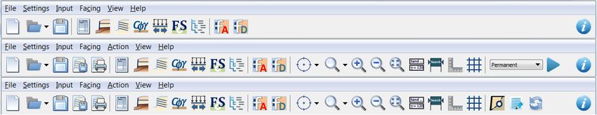
Snail User Guide March 2020

2 How to Use Snail

Snail has seven main menus: File, Settings, Input, Facing, Action, View, and Help (Figure
1). The Action menu is available only after geometry or reinforcement information is entered.

 Figure 1 Snail Menus and Toolbars

File

The File menu includes standard file handling functions usually found in Windows-based
programs: New, Open, Save, Save As, Save as Image File, Print, and Exit.

Settings

The Settings menu allows users to select

 • Analysis method: allowable stress design (ASD) or load and resistance factor design
 (LRFD); and
 • Units: English or SI.

When analysis method ASD is selected, the icon for the entry of factors of safety for ASD
will appear in the toolbar. When the analysis method LRFD is selected, the icon for the entry
of load and resistance factors for LRFD will appear in the toolbar.

 Page |2
Snail User Guide March 2020 Input The Input menu is for entering information required for soil nail wall analyses. The Input menu has six submenus: Project Information, Geometry, Soil Nails, Soil Properties, Loads, Factors of Safety or Load and Resistance Factors, and Search Options. Project Information Figure 2 Project Information Project information is the input screen to enter project name or description, location, expenditure authorization (EA) number, project ID, wall number, structure number, station, the user’s name, and function (Figure 2). The Comments field can be used for project and site descriptions. Geometry Geometry includes four tabs: Layout, Ground Surface, Soil Layers, and Ground Water (Figure 3). Layout Snail uses the combination of an origin point, reference point, wall height, and facing angle or batter to establish the wall geometry. The origin point can be any point as defined by the user. The reference point must be at one of two locations, at the top of the wall or the toe of the wall, as shown on Figure 6. Assign the coordinates of the reference point, either Page |3
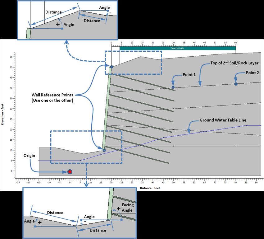
Snail User Guide March 2020 the toe or top of the wall, based on the horizontal distance (x) and the vertical distance (y) from the origin point. Reference point • At: Set the reference point at either the Top of Wall or the Toe of Wall (Figure 6). • Distance from Origin: Enter x-coordinate of the reference point • Elevation above Origin: Enter y-coordinate of the reference point Wall Dimensions • Wall Height: Enter the wall height • Facing Angle: Enter the wall inclination in degrees, measured from the horizontal axis with counter-clockwise direction as positive (Figure 6), or • Facing Batter: Enter the horizontal “x” value for the wall facing Batter of x:12 (H:V) .(The angle is automatically calculated based on the ratio of the horizontal distance and the vertical distance.) Figure 3 Geometry - Layout Based on the reference point coordinates, either the top-of-wall or toe-of-wall coordinates will be determined by the wall height and facing angle or facing batter. If the facing angle is entered, the facing batter will be automatically calculated and shown on the input screen or vice versa. Page |4
Snail User Guide March 2020 Ground Surface • Number of lines that define the ground surface above the wall: Use up to 19 line segments • Angle: Enter the inclination angle (from horizontal) of each line segment with the above horizontal line direction as positive for the ground surface above the wall and in front of the toe (Figure 6). • Distance: Enter the length of each line (Figure 6) The number of inputs for Angle and Distance (Figure 4) must match the value entered for Number of lines that define the ground surface above the wall. The first ground surface line starts from the top of wall; the second line starts from the end point of the first line etc. From the entered angle and length for each line, the x and y coordinates of the points connecting the lines will be calculated and the surface lines will be shown on the graphic screen (Figure 6). The Distance for the last entry is internally calculated and projected to the limits of the model by the software. Figure 4 Geometry - Ground Surface If a below toe search (with Perform below Toe Search of Search Options selected) is to be performed, enter the Number of lines that define the ground surface in front of the toe. The first ground surface line in front of the wall starts from the toe of the wall, the second line starts from the end point of the first line and continues until the last line. Page |5
Snail User Guide March 2020 Soil Layers • Number of Layers: Select number of layers – up to 7 • Distance: Enter x-coordinate of Point 1 and Point 2 of the top of each layer • Elevation: Enter y-coordinate of Point 1 and Point 2 of the top of each layer Figure 5 Geometry - Soil Layers Enter the top of each soil layer (Figure 5), starting from the top of the second layer, as the top of first layer has been defined by the ground surface. Enter coordinates of Point 1 and Point 2 that form a straight line that defines the top of each soil layer (Figure 6). The location of these points must be below the defined ground surface lines, behind the wall face, and inside the wall model area. To ensure the points are behind the wall, placing the points at a discernible distance behind the wall face. The lines and their projection must not intersect each other within the model boundaries. Snail will calculate the coordinates of the points where the lines intersect the wall face and model boundaries based on the inclination projection of the defined straight lines. Page |6
Snail User Guide March 2020 Figure 6 Geometry - Graphical Presentation of Input Variables Ground Water • Include Ground Water: Check the box (Figure 7) when ground water is considered in the analysis • Number of Points: Select the number of points that define the ground water surface – up to 18 • Distance: Enter the x-coordinate of each point • Elevation: Enter the y-coordinate of each point The number of inputs for Distance and Elevation must match the value selected in the Number of Points. Ensure the ground water line is below the ground surface. The ground water table will project horizontally outward from the first and last points (Figure 6). Page |7
Snail User Guide March 2020

 • Phreatic Correction: Check the box to apply phreatic surface correction

 Figure 7 Geometry - Ground Water

 For a ground water system under hydrostatic condition, the pore-water pressures may
 be calculated by multiplying the vertical distance between the ground water surface
 and the slice base mid-point (Hw) and the unit weight of water (γw).

 = ×

 However, when there is a sloping ground water condition (Figure 8), using the vertical
 distance to calculate pore-water pressures will result in a higher pore-water pressure
 than necessary. To take into account the sloping piezometric profile for more accurate
 calculation of pore-water pressure, the user can apply the phreatic surface correction.

 Figure 8 Phreatic Surface Correction

 Page |8
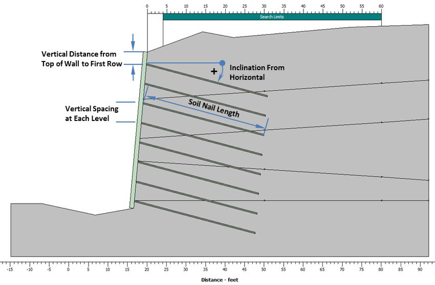
Snail User Guide March 2020 = × cos2 ( ) = × For sloping ground water conditions, the calculation without phreatic surface correction yields a lower factor of safety than when phreatic correction is applied and is erring on the conservative side. If there are ground water issues for the wall, a soil nail wall may not be a good option. Soil Nails Soil Nails has two tabs: Dimensions and Properties (Figures 9, 10, and 11), and Facing Resistance (Figure 12). Dimensions and Properties • Diameter of Drilled Holes: Enter drilled-hole diameter (typical practice uses 6 or 8 inches) • Horizontal Spacing: Enter center to center horizontal distance between nails • Maximum Vertical Spacing: Enter maximum vertical spacing between nails – for To calculation (refer to Section 4 – Tensile Force at Soil Nail Head (To)) • Number of Soil Nail Rows: Select the number of soil nail rows – up to 30 • Soil Nail Design Parameters: Select either Uniform throughout Cross-Section or Varying For Soil Nail Design Parameters, when the Uniform throughout Cross-Section option is selected enter the following fields (Figure 9): • Soil Nail Length: Enter soil nail length • Inclination From Horizontal: Enter the inclination angle of soil nails measured from the horizontal axis with clockwise direction as positive (Figure 10) – typically 10 to 15 degrees • Vertical Distance from Top of Wall to First Row: Enter the vertical distance from top-of-wall to the first row of soil nails • Vertical Spacing: Enter the center-to-center vertical spacing between soil nail rows • Nail Bar Diameter: Enter soil nail bar diameter • Nail Bar Yield Strength: Enter soil nail bar yield strength Page |9
Snail User Guide March 2020

 Figure 9 Soil Nails – Uniform Throughout Cross Section Option

 Figure 10 Soil Nails - Graphical Presentation of Input Variable

 When the Varying option is selected for Soil Nail Design Parameters, the lower portion
 of the window will turn into a table for entry of the parameters for each soil nail row
 (Figure 11).

 P a g e | 10
Snail User Guide March 2020 In the table, the entries for vertical spacing is the vertical spacing above the corresponding soil nail row. For the first soil nail row, the vertical spacing entry is the vertical distance from top of wall to the first soil nail row. In the table, the entries for bond strength factor, with defaulted value of “1”, can be used to account for variation of construction methods and scenarios for different soil nail rows, such as localized variations of soil condition in a soil layer. Figure 11 Soil Nails - Varying Option Facing Resistance Snail offers analyses of both Allowable Stress Design (ASD) and Load and Resistance Factor Design (LRFD), and for three scenarios: Temporary, Permanent, and Seismic. Each scenario requires its own set of facing resistance factors for corresponding analysis (Figures 12 and 13). Allowable Stress Design (ASD) • ASD Allowable Facing Resistance: Enter the ASD allowable facing resistance for the three scenarios or select Facing Design Tool • Facing Analysis: Click the button to have Snail perform facing analysis and calculate the factored facing resistances and automatically transfer the calculated factored facing resistance parameters to the corresponding fields above P a g e | 11
Snail User Guide March 2020 • Suggested Facing Design: Click the button to select one of the suggested facing designs and automatically transfer the factored facing resistances of the selected facing design to the corresponding fields above The ASD Allowable Facing Resistance can be entered by the user, calculated by Facing Analysis, or obtained from Selected Facing Design features in Snail and automatically transferred to the corresponding fields for soil nail wall analysis. Facing Analysis and Suggested Facing Design, as activated by clicking the respective buttons (Figure 12), are stand-alone structural facing analyses tools. The required input parameters for facing design and analysis are described in the Facing Analysis section. ASD allowable facing resistances are factored strength values that accounts for uncertainties associated with structural facing design and facing strength properties. Figure 12 Facing Resistance Tab in Soil Nails Menu – ASD Load and Resistance Factor Design (LRFD) For LRFD analysis, enter LRFD factored facing resistance for each of the three scenarios: Temporary, Permanent, and Seismic (Figure 13). LRFD factored facing resistances are factored strength values that accounts for uncertainties associated with structural facing design and facing strength properties. The LRFD factored facing resistances can be entered by the user, calculated by Facing Analysis, or obtained from Selected Facing Design features in Snail and automatically transferred to the corresponding fields for soil nail wall analysis. P a g e | 12
Snail User Guide March 2020

 Figure 13 Facing Resistance Tab in Soil Nails Menu – LRFD

Soil properties

The number of sets of soil properties inputs (Figure 14) must match the Number of Layers
selected in Soil Layers tab in Geometry menu.

 • Description: Enter the description for each soil layer
 • Unit Weight: Enter the unit weight for each soil layer
 • Friction Angle: Enter the friction angle for each soil layer
 • Cohesion: Enter the cohesion for each soil layer
 • Nominal Bond Strength: Enter nominal bond strength for each soil layer

 Figure 14 Soil Properties

 P a g e | 13
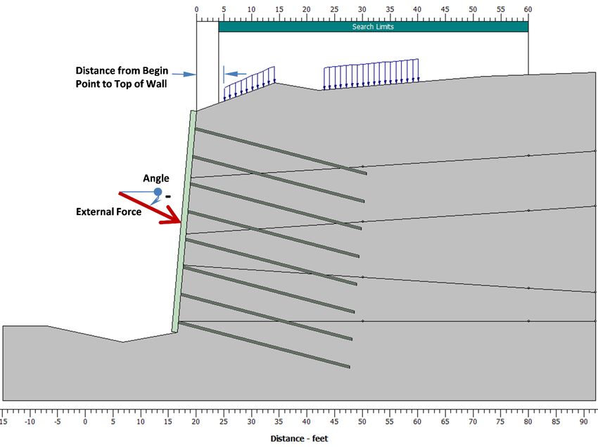
Snail User Guide March 2020 Loads Snail offers three different load options: Seismic, External and Surcharge (Figures 15 and 16). Seismic • Horizontal Seismic Coefficient: Enter the horizontal seismic coefficient. The horizontal seismic coefficient must be provided if seismic analysis is to be performed. The effect of vertical seismic force on a wall is typically negligible and is not considered. External • Apply External Load: Check the box when there is an external load onto the wall face. • Load: Enter the external load • Angle: Enter the inclination angle of external load direction measured from the horizontal axis with counter- clockwise direction as positive. (Figure 16). Note: The location of the external load on the wall face is not needed because the analysis is performed using force equilibrium method. Surcharges • Apply Surcharges: Check the box when there are distributed loads on the ground above the wall • Number of Surcharges: Select a value – up to 2 • Distance from Top of Wall: Enter the distances of begin point and end point of each distributed load from top of wall • Load: Enter the distributed loads at begin point and end point of each distributed load P a g e | 14
Snail User Guide March 2020

 Figure 15 Loads

 Figure 16 Applied Loads - Graphical Presentation of the Input

 P a g e | 15
Snail User Guide March 2020

Factors of Safety – for ASD

 Enter Factors of Safety for the Temporary, Permanent, and Seismic scenarios. Each
 scenario requires its own set of factors of safety for corresponding analysis (Figure
 17).

 • Pullout (Distal): Enter the factors of safety to be applied to the pullout capacity
 of soil nail grout / soil interface at the distal section of the soil
 nails.
 • Pullout (Proximal): Enter the factors of safety to be applied to the pullout capacity
 of soil nail grout / soil interface at the proximal section of the
 soil nails.
 • Nail Bar Yield: Enter the factors of safety to be applied to soil nail bar yield

 Note: The introduction of separate resistance factors for distal
 and proximal pullout capacities is for future implementation to
 take into account the difference in the reliability of the
 estimated pullout capacities.

 The estimated pullout capacity at the section near the soil nail
 tip (distal) should be more reliable, as it will be verified and
 proved by pullout test during construction. Therefore, the
 resistance factors applied to the distal pullout capacity may be
 greater than those applied to the proximal pullout capacity.
 To assign different pullout resistance factors for proximal and
 distal sections, a more rigorous pullout test regime during
 construction should be implemented.

 For recommended factors of safety, please refer to Table 5.1, GEC No. 7 2015. As
 explained above, the confidence on the estimated pullout capacities depend on the
 rigorousness of pullout test during design and specified during construction. Factors of
 safety values other than those recommended by GEC No. 7 2015 may be considered
 if rigorous pullout test regime has been carried out during design or to be performed
 during construction as specified.

 Figure 17 Factors of Safety

 P a g e | 16
Snail User Guide March 2020 Load and Resistance Factors – for LRFD Load and Resistance Factors includes two tabs: Load Factors (Figure 18) and Resistance Factors (Figure 19). Load Factors Snail offers two options to apply load factors: • Apply to Soil Nail Tensile Force (FHWA GEC No. 7 2015); or • Apply to Loads and Soil Weight. Soil Nail Tensile Force (FHWA GEC No. 7 2015) Enter the load factors to be applied to the soil nail tensile force – recommended option. Note: The default load factors for Soil Nail Tensile Force are derived from the “EV: Vertical earth pressure (ret. walls and abutments)” row of Table 5.3, GEC No. 7 2015. The combination of these default load factors (ϕ) and the default resistance factors (γ) applied to soil nail pullout capacities, soil nail bar yield, and facing capacity will arrive at the factors of safety (FoS) for the respective components that are compatible with the FoS used in the ASD method. These load factors on soil nail tensile force are virtual load factors implemented as an interim solution before there is a decision on load factors for soil mass and external loads. Figure 18a Load Factors – Applied to Soil Nail Tensile Force P a g e | 17
Snail User Guide March 2020 Loads and Soil Weight When this option is selected, Snail can be used to implement LRFD design of soil nail walls. However, policy decision is needed before using this option for actual design work. In the meantime, this option can be used to perform parametric studies. • Active Soil Mass Load: Enter the load factor for weight of soil mass in active zone • Passive Soil Mass Load: Enter the load factor for weight of soil mass in passive zone in front of the toe. This value will only be used when Perform below Toe Search in Search Option is checked; and should be ≤1.0 since this load is a stabilizing force in the soil nail stability analysis. • Surcharge Load 1: Enter the load factor for Surcharge Load 1 • Surcharge Load 2: Enter the load factor for Surcharge Load 2 • External Load: Enter the load factor for the External Load. If the load against the slope or wall face acts as a stabilizing force to the slope or wall, the value should be ≤ 1.0. Please refer to Section 4 Technical Note Use LRFD Method for Soil Nails for further discussion of the load factors on soil nail tensile force, soil mass, and external loads. Figure 18b Load Factors – Applied to Loads and Soil Weight Resistance Factors • Pullout (Distal): Enter the resistance factors for the pullout capacity of soil nail grout / soil interface at the distal section of the soil nails P a g e | 18
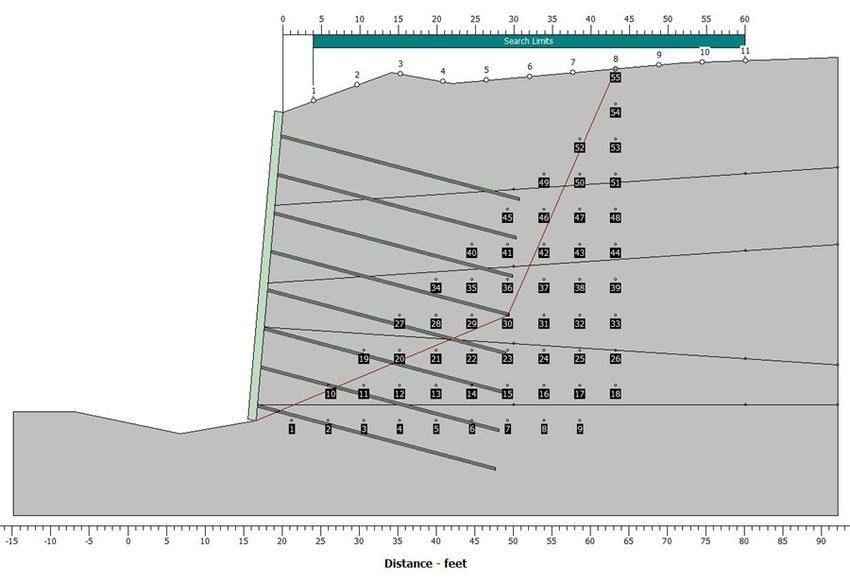
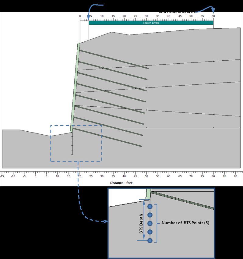
Snail User Guide March 2020 • Pullout (Proximal): Enter the resistance factors for the pullout capacity of soil nail grout / soil interface at the proximal section of the soil nails • Nail Bar Yield: Enter the resistance factors for the soil nail bar yield • Friction Angle: Enter the resistance factor for friction angle • Cohesion: Enter the resistance factor for cohesion • Friction Angle: Enter the resistance factor for friction angle Note: The introduction of separate resistance factors for distal and proximal pullout capacities is for future implementation to take into account the difference in the reliability of the estimated pullout capacities. The estimated pullout capacity at the section near the soil nail tip (distal) should be more reliable, as it will be verified and proved by pullout test during construction. Therefore, the resistance factors applied to the distal pullout capacity may be greater than those applied to the proximal pullout capacity. To assign different pullout resistance factors for proximal and distal sections, a more rigorous pullout test regime during construction should be implemented. For recommended resistance factors, please refer to Table 6.3, GEC No. 7 2015. Figure 19 Resistance Factors Search Options Search Limits • Begin: Enter the horizontal distance between the top of wall and the begin point of the search (Figures 20 and 21) P a g e | 19
Snail User Guide March 2020 • End: Enter the horizontal distance between the top of wall and the end point of the search Figure 20 Search Options The distance between the Begin and End points of search limits will be equally divided into 10 segments to generate eleven search Nodes. From each of these search Nodes, 55 bi-linear search surfaces will be generated with a matrix of 55 Grid Points (Figure 22) to search for the surface with the minimum factor of safety (FoS) or capacity demand ratio (CDR) for each search Node. The minimum factors of safety or capacity demand ratio for each search Node are presented in the Snail text output file. Snail also allows users to view the calculated factor of safety or capacity demand ratio and geometry of any search surface by selecting the corresponding search Node and Grid Point. This option is described in View Details in Action Menu. Below Toe Search (BTS) When the Perform Below Toe Search option is selected, Number of BTS Point, BTS Depth and Interface Friction Reduction Factor are available for entry. Search points for below the toe search will be generated according to the Number of BTS Points and BTS Depth. • Perform Below Toe Search: Check the box to search for the minimum factor of safety of surfaces that pass through below the toe of wall (Figure 21) • Number of BTS Points: Select the number of search points – up to 5 • BTS Depth: Enter vertical extent of the search from the toe of wall – should be less than the wall height P a g e | 20
Snail User Guide March 2020

 • Interface Friction Reduction Factor:
 Enter the reduction factor for the interface friction
 mobilized by friction angle at the vertical interface
 between active zone and passive zone – should be
 0 ≤ value ≤ 1.0

 The use of Interface Friction Reduction Factor is to reduce shear resistance at the
 interface between active and passive sliding wedges. This value is a multiplier to the
 mobilized shear resistance along the interface contributed by the friction angle. Enter
 “1.0” to assume a fully mobilized shear resistance from friction angle. The default
 value is set to 0.33 to be consistent with the previous versions of the software.

 P a g e | 21
Snail User Guide March 2020 Figure 21 Entries for Below the Toe Search Figure 22 Nodes, Grid Points, and Bi-linear Search Surface Advanced Search Options Snail also includes advanced search options that allow users to perform parametric studies of the effects of inter-slice force inclination angle on the analysis results. Figure 23 Advanced Search Options P a g e | 22
Snail User Guide March 2020

 • Use Advanced Search Options: Check the box to allow the user to change the
 inter-slice force inclination angles from default
 values
 • Inclination of Inter-slice Force: Select Use Input Value, Use Mobilized Friction
 Angle, or Use Average Failure Angle.

 If Use Input Value is selected, a field will appear under the selection for the user to
 enter the value of the user-defined inclination angle. If Use Mobilized Friction Angle is
 selected, average mobilized friction angles (average friction angle/FoS) along vertical
 interfaces of slices will be the inter-slice force inclination angle. If Use average Failure
 Angle is selected, the average of base angles of the active wedges of each search
 surface will be the inter-slice force inclination angle.

 In the default setting, without checking the box for Use Advanced Search Options,
 inter-slice forces consist of both the shear force and inclined force components. The
 shear force component is from the mobilized cohesion (average cohesion/FoS); while
 the inclined force component is acting at the direction equal to the average mobilized
 friction angles (average friction angle/FoS).

 The inclined force component in the default setting is the same as the inclined force
 component applied in the Use Mobilized Friction Angle in Advance Search Options.
 However, the Use Mobilized Friction Angle in Advance Search Options does not
 account for the mobilized cohesion.

Action

The Action menu has two options before performing the analysis: Select Analysis Scenario
and Run; and three options after the analysis: View Details, Create Report, and Clear
Results.

 • Select Analysis Scenario: Select an analysis scenario – temporary, permanent, or
 seismic
 • Run: Click to run the selected analysis scenario
 • View Details: Click to view details of calculated results
 • Create Report: Click to create and view the report. Then, the user can
 save or print the report. Clear Results: Click to clear
 calculated result, so that the Run function in Snail can be
 available again

After running an analysis, Snail will display the calculated minimum Factor of Safety (FoS) or
Capacity Demand Ratio (CDR), the check of entered Factored Facing Resistance (Ffactored)
vs. the calculated Service Load at Soil Nail Head (To), and corresponding graph (Figures 24a,
24b, and 25). Please refer to Technical Notes for the background of checking Ffactored vs. To.

 P a g e | 23
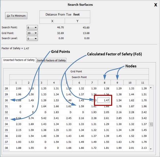
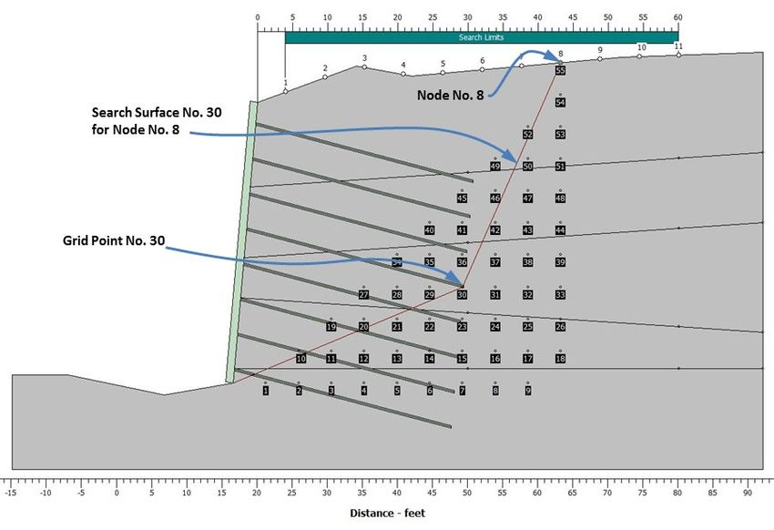
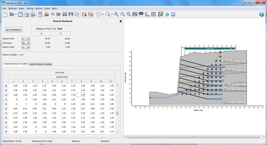
Snail User Guide March 2020

 Figure 24a Results – ASD

 Figure 24b Results – LRFD

Details of any search surface can be examined by selecting View Details. A 2-pane window
will open as shown in Figure 25.

The left pane includes a table showing the calculated factors of safety for all the search
surfaces. Above the table are three pull-down lists, Node, Grid Point, and BTS Point that
allow users to select and view the calculated factor of safety, and geometry of any search
surface on the right pane. To view a particular search surface, select the values available in
the pull-down lists.

Node is the Node number, between 1 and 11, to be selected to view the search surface
passing through the search Node. Node 1 is the begin point; and Node 11 is the end point of
the search limits.

For each selected Node, 55 Grid Points and associated calculated factor of safety and the
search surface corresponding to the selected Grid Point are shown graphically on the right
pane (Figures 25 and 27).

BTS Point can be selected to view a search surface passing below the toe. When BTS is not
performed, the value shown on the window is set to “0”. When BTS is performed with the “N”
BTS Points, select a value between 0 and N with “0” representing the search surfaces
passing through the toe, and “N” representing the search surface passing through the lowest
extent of the BTS.

 P a g e | 24
Snail User Guide March 2020

Tables of unsorted and sorted calculated factor of safety are available for viewing by
selecting among the corresponding tabs.

 Figure 25 View Details

 Figure 26 View Details Left Pane – Table Presentation

 P a g e | 25
Snail User Guide March 2020

 Figure 27 View Results Right Pane – Graphical Presentation

 P a g e | 26
Snail User Guide March 2020

Facing

The Facing menu includes two options: Facing Analysis and Suggested Facing Design. The
factored facing resistance calculated by Facing Analysis or by the Suggested Facing Design
can be automatically transferred to the factored facing resistance entry for soil nail analysis.

Snail implements the facing analysis and design procedure presented in Soil Nail Walls
Reference Manual, FHWA-NHI-14-007, FHWA GEC 007, February 2015. Users are advised
to have GEC No. 7 2015 available while using this module. This Guide provides the section
and table numbers of the subject matter described in GEC No. 7 2015 after each of the
following entry descriptions.

Facing Analysis

Facing Analysis can be used as a stand-alone module. Snail calculates factored facing
resistances for the three scenarios: Temporary, Permanent and Seismic using entered
design parameters (Figure 28). The results can be saved to the active input file and re-loaded
for soil nail stability analysis.

The required entries for Facing Analysis are organized into seven tabs. The Results tab
shows the results and allow the user to transfer the results for analysis of soil nails.

 Figure 28 Facing Analysis – Analysis

 P a g e | 27
Snail User Guide March 2020 Analysis • Temporary Shoring Only: Check the box if the facing is for temporary shoring only; Snail will turn off the entry fields for permanent facing design values. • Check Bearing Plate Capacity: Check the box if bearing plate design details were available and needed to be checked. Snail will turn on 5 additional fields under Bearing Plate tab, and 4 additional fields under ASD Factors of Safety or LRFD Resistance Factors tab for entry of bearing plate design details and perform the analysis. This option is mostly for checking shop drawings, as bearing plate design details are mostly not available during design, and mostly determined and provided by the contractor in shop drawing. • Easy Start: Easy Start offers users a convenient way to quickly start manipulating and fine-tuning structural facing design parameters for analysis. After clicking the Easy Start button, the user can select one of the seven designs in Suggested Facing Design (Figures 40 and 41). The values for the selected design will be pre-populated to all the Facing Analysis fields; and the user can then fine-tune these values before performing facing analysis. Soil Nails • Horizontal Spacing: Horizontal spacing of soil nails • Vertical Spacing: Vertical spacing of soil nails P a g e | 28
Snail User Guide March 2020 Figure 29 Facing Analysis – Soil Nails Facing • Facing Thickness (Temporary): h as shown in Figure 31 • Facing Thickness (Permanent): H as shown in Figure 35 Figure 30 Facing Analysis – Facing P a g e | 29
Snail User Guide March 2020 •Vertical and Horizontal Reinforcement Area: Reinforcement cross sectional area per unit width in the vertical/horizontal direction – for welded wire mesh, obtained by dividing the wire cross-sectional area by the mesh opening size (Tables A.5 and A.6, GEC No. 7 2015) • No. of Vertical and Horizontal Waler Bar: The number of vertical and horizontal waler bars • Waler Bar Area: The cross sectional area of waler bar assuming the same size bar is used both horizontally and vertically as shown in Figure 26 (Table A.6, GEC No. 7 2015) • Concrete Yield Strength: Concrete yield strength • Reinforcement Yield Strength: Reinforcement yield strength • Punching Correction Factor: Factor to account for soil pressure distribution behind the facing (Section 6.6.6, GEC No. 7 2015) • Flexural Correction Factor: Factor to account for soil pressure distribution behind the facing (Table 6.5 and Section 6.6.5b, GEC No. 7 2015) Bearing Plates • Width/Height: LBP as shown in Figure 31 • Thickness: tP as shown in Figure 31 DC D’C Waler Bar (Typ) Conical Failure L BP Surface 45° (Typ) Shear Resistance RF/2 tp h h/2 Idealized Soil Reaction T0 DDH Figure 31 Temporary Bearing Plate Connection P a g e | 30
Snail User Guide March 2020

 Figure 32 Facing Analysis – Bearing Plates

 Additional 5 fields are available for entry if Check Bearing Plate Capacity box under
 Analysis tab is checked

 • Bearing Plate Hole Diameter: DB as shown in Figure 33
 • Wedge Washer Diameter: Dw as shown in Figure 33
 • Concrete Hole Diameter: DConcrete as shown in Figure 33 (may also be soil nail
 sheathing diameter)
 • Bearing Plate Yield Strength: Bearing Plate Yield Strength
 • Bearing Plate Tensile Strength: Bearing Plate Tensile Strength

 L BP
 DW
 DB
 P

 tp

 DConcrete
 Figure 33 Bearing Plate Details (mostly from Shop Drawing)

 P a g e | 31
Snail User Guide March 2020 Studs Figure 34 Facing Analysis – Studs • Number of Studs: Typically 4 (Table A.7, GEC No. 7 2015) • Stud Head Diameter: DH as shown in Figure 36 (Table A.7, GEC No. 7 2015) • Head Thickness: tH as shown in Figure 36 (Table A.7, GEC No. 7 2015) • Head-Stud Length: LS as shown in Figure 36 (Table A.7, GEC No. 7 2015) • Stud Shaft Diameter: DS as shown in Figure 36 (Table A.7, GEC No. 7 2015) • Stud Spacing: SHS as shown in Figure 35 (Table A.7, GEC No. 7 2015) • Stud Tensile Strength: Stud tensile strength P a g e | 32
Snail User Guide March 2020 DC D’C Composite Conical Failure SHS Shear Resistance RF/2 Surface 45° (Typ) H LS h DH tp C tH h h/2 LS DS Idealized Soil Reaction T0 DDH Figure 35 Permanent Head-Studded Connection Figure 36 Head Stud ASD Factors of Safety Figure 37 Facing Analysis – ASD Factors of Safety • Flexural: The factors of safety to account for uncertainties associated with design and strength properties • Punching: The factors of safety to account for uncertainties associated with design and strength properties P a g e | 33
Snail User Guide March 2020 • Stud Tensile: The factors of safety to account for uncertainties associated with design and strength properties Additional 4 fields are available for entry if “Check Bearing Plate Capacity” box under Analysis tab was checked • Tensile Stress: The factors of safety to account for uncertainties associated with design and strength properties • Flexure: The factors of safety to account for uncertainties associated with design and strength properties • Bearing Stress of Steel The factors of safety to account for uncertainties associated with design and strength properties • Bearing Stress of Concrete/Shotcrete: The factors of safety to account for uncertainties associated with design and strength properties LRFD Resistance Factors Figure 38 Facing Analysis – LRFD Resistance Factors • Flexural: The reduction factor to account for uncertainties associated with design and strength properties • Punching: The reduction factor to account for uncertainties associated with design and strength properties P a g e | 34
Snail User Guide March 2020 • Stud Tensile: The reduction factor to account for uncertainties associated with design and strength properties Additional 4 fields are available for entry if Check Bearing Plate Capacity box under Analysis tab was checked • Tensile Stress: The reduction factor to account for uncertainties associated with design and strength properties • Flexure: The reduction factor to account for uncertainties associated with design and strength properties • Bearing Stress of Steel The reduction factor to account for uncertainties associated with design and strength properties • Bearing Stress of Concrete/Shotcrete: The reduction factor to account for uncertainties associated with design and strength properties Results • Allowable or Factored Resistance: For Temporary, Permanent, and Seismic scenarios (Figure 39) • Capacity Ratio: Display the capacity ratio (normalized by control mode capacity). The presentation of the capacity ratio shows which design modes are over capacity and by how much. The design mode with capacity ratio equals to one is the controlling mode for the respective analysis scenario. • Allowable or Factored Bearing Plate Resistance: Display factored bearing plate resistances • Create Report: Click to create and view the report. Then, the user can save or print the report. • Clear Results: Click to clear calculated result, so that the Run function in Snail can be available again • Transfer Results: Click the button to transfer the controlling allowable or factored facing resistances of respective scenario to the Soil Nail input form as input for soil nail stability analysis P a g e | 35
Snail User Guide March 2020

 Figure 39 Facing Analysis – Results

Suggested Facing Design

 Figure 40 Suggested Facing Design Template – Design Details

 P a g e | 36
Snail User Guide March 2020 Suggested Facing Design allows users to select from typical facing design developed by Caltrans (Figures 40 and 41). The users can select a facing design from the Facing Design Template and click on the Transfer Data button. Then, the Allowable Facing Resistances (for ASD) or the Factored Facing Resistances (for LRFD) of the design for temporary, permanent and seismic scenarios are automatically transferred to the Soil Nails input form as input for soil nail stability analysis. There are two tabs in Suggested Facing Design – Design Details and Facing Resistances. Design Details Design Details shows the detailed configuration of each typical facing design. Facing Resistances Facing Resistances (Figure 41) includes two parts – the Facing Resistances Table, and the Factors of Safety or Reduction Factors. • Facing Resistances Table: Display both Nominal Facing Resistances and ASD Allowable Facing Resistances or LRFD Factored Facing Resistances. The ASD Allowable Facing Resistances or LRFD Factored Facing Resistances are calculated based on the Nominal Facing Resistances and values entered into the Resistance Factors fields. • Factors of Safety / Resistance Factors: Default values of ASD Factors of Safety and LRFD Resistance Factors are prepopulated. These default values are the recommended values from Table 5.1 and Table 6.3, GEC No. 7 2015. Snail allows users to adjust these values for special design cases. When the values were adjusted from the default values, the values under ASD Allowable Facing Resistances or LRFD Factored Facing Resistances will be automatically updated. Meanwhile, the background of the adjusted fields will turn light yellow and Snail will prompt the notice of “Not a Default Value”. Users may click on the “Reset to Default Values” button to reset the values to the default values. Create Report Click the Create Report button to create and view the report for the selected facing design. Then, the user can save or print the report. P a g e | 37
Snail User Guide March 2020 Transfer Data Click the Transfer Data button to transfer the allowable facing resistances or factored facing resistances to the Soil Nails input form as input for soil nail stability analysis. Figure 41 Suggested Facing Design Template – Facing Resistances P a g e | 38
Snail User Guide March 2020

View

The View menu has twelve options for viewing the created wall model and to toggle on or off
the toolbar and status bar.

The View menu options are:

 • Measure From: Select Origin, Top of Wall, or Toe of Wall to change the
 coordinate reference of the model view
 • Magnification: Select the magnification of the view
 • Zoom In: Click to zoom in
 • Zoom Out: Click to zoom out
 • Fit: Click to fit the whole model into view
 • Show/Hide Input Values: Click to show/hide input values
 • Show/Hide Search Limit: Click to show/hide search limit
 • Show/Hide Scale: Click to show/hide scale
 • Show/Hide Gridlines: Click to show/hide grid
 • Toolbar Button Size: Select Large or Small button size – Small button size is
 recommended for using Snail in a laptop computer
 • Hide/Show Toolbar: Click to toggle Toolbar on/off
 • Hide/Show Status Bar: Click to toggle Status Bar on/off

Help

The Help Menu includes Snail Home Page, Snail User Guide, and About.

 • Snail Home Page: Click to open the Snail home page via hyperlink.
 • Snail User Guide: Click to open this User Guide on line via hyperlink. The file can be
 navigated using the bookmarks created for the file. The user
 should check this hyperlink for the latest revision of the User
 Guide.
 • About: Click to see the Snail version, Legal Notice, and copyright
 information

 P a g e | 39
Snail User Guide March 2020

3 Theory

Snail analyzes soil nail wall system stability based on force limit equilibrium. The software
generates bi-linear surfaces through the toe of wall, or tri-linear surfaces which pass below
the toe and daylight in front of the wall, to calculate and search for the minimum factor of
safety of the selected analysis scenario. Even though Snail can perform stability analysis for
“deep-seated” failure modes using a tri-linear wedge search, it is not suitable for global slope
stability analysis. Global stability of soil nail walls should be analyzed using slope stability
software.

For ease of discussion and presentation, the term factored resistances used in this section
refers to the resistances that have been factored, i.e. divided by the FoS (for ASD), or
multiplied by the resistance factor, ϕ (for LRFD).

Derivation

 1 × 1 +( 1 − 1 )×tan( )
 1 =
 1

 2 × 2 +( 2 − 2 )×tan( )
 2 =
 2

 Figure T-1 Forces and Directions on Bilinear Wedge Elements

The above figure (Figure T-1) shows the two wedge elements and associated forces
generated by Snail for the bi-linear surface mode calculation.

The following is the derivation of equations used by Snail:

 P a g e | 40
Snail User Guide March 2020

↑ � 1 = 0

 ⇒ −( × sin( 1 − )) − ( 1 × cos( 1 )) + ( × sin( 1 )) + ( × sin( − 1 )) −
 ( 1 × sin( 1 + 1 )) − ( 1 × cos( 1 )) − ( 1 × cos( 1 )) + ( 1 × sin( 1 − )) +
 1 = 0

 ⇒ 1 = ( × ( 1 − )) + ( 1 × ( 1 )) − ( × sin( 1 )) − ( ×
 sin( − 1 )) + ( 1 × sin( 1 + 1 )) + ( × cos( 1 )) + ( 1 × cos( 1 )) −
 ( 1 × sin( 1− ))
 Equation 1

→ ∑ 1 = 0

 ⇒ ( × cos( 1 − ) ) − ( 1 × sin( 1 )) − ( 1 × cos( 1 )) + ( × cos( − 1 )) +
 ( 1 × cos ( 1 + 1 )) − ( 1 × sin( 1 )) − ( 1 × sin( 1 )) − ( 1 × cos( 1 − )) +
 � 1 × 1 +�( 1 − 1 )×tan( )��
 =0
 1

 ⇒ 1 = [ 1 × 1 + �( 1 − 1 ) × tan( )�]/[−( × cos( 1 − ) ) + ( 1 × sin( 1 )) +
 ( 1 × cos( 1 )) − ( × cos( − 1 )) − ( 1 × cos ( 1 + 1 )) +
 ( 1 × sin( 1 )) + ( 1 × sin( 1 )) + ( 1 × cos( 1 − ) ) )]

 −
 ⇒ 1 = cos(
 1 − )

 Equation 2

 where

 = ( × s( 1 − )) + ( × s( − 1 )) + ( 1 × s( 1 + 1 )) + 1

 = �( 1 × ( 1 )� + � 1 × ( 1 )� + � 1 × ( 1 )� + � 1 × ( 1 )�)

 P a g e | 41
Snail User Guide March 2020

↑ � 2 = 0

 ⇒ −( 2 × cos( 2 ) + ( 2 × sin( 2 )) − ( 2 × sin( 2 + 2 )) − ( 2 × cos( 2 )) +
 ( 2 × cos( 2 )) − ( 2 × sin( 2 − )) + 2 = 0

 ⇒ 2 = ( 2 × cos( 2 ) − ( 2 × sin( 2 )) + ( 2 × sin( 2 + 2 )) + ( 2 × cos( 2 )) −
 ( 2 × cos( 2 )) + ( 2 × sin( 2 − ))
 Equation 3

→ � 2 = 0

 ⇒ −( 2 × sin( 2 )) − ( 2 × cos( 2 )) + ( 2 × cos( 2 + 2 )) − ( 2 × sin( 2 )) +
 � 2 × 2 +�( 2 − 2 )×tan( )��
 ( 2 × sin( 2 )) + ( 2 × cos( 2 − )) + =0
 2

 ⇒ 2 = (( 2 × 2 + (( 2 − 2 ) × tan( ) )))/(( 2 × sin( 2 ) + ( 2 × cos( 2 )) −
 ( 2 × cos( 2 + 2 )) + ( 2 × sin( 2 )) − ( 2 × sin( 2 )) − ( 2 × cos( 2 − ) ) )

 = 1 = 2 ; = 2 = 1 ;

 ∑ ℎ
 = ;
 ∑ + − ∑

 = 1 = 2 ;

 =

Equation 4

where

 2

 = �( × + ( − ) × tan( ))
 =1

 P a g e | 42
Snail User Guide March 2020
 2

 = �[( × sin( )) + ( × cos( )) + ( × sin( )) − ( × cos( + ))]
 =1

 + { × [cos( 1 − ) − cos( 2 − )]} + ( × ( 1 − 2 )) − ( × (cos( 1 − ))
 − ( × (cos( − 1 ))

Average equilibrium condition over two wedges is assumed for Equation (4).

 = Weight of each slice of soil

 = Seismic force on each slice

 = External load applied on the wall face

 = Total resistance from soil nails over each slice

 = Normal force acting on sliding surface

 = Water pressure acting on sliding surface

 = Surcharge load acting on ground surface

 = Friction angle

 = Cohesion

 = 2 = 1 = Inter-slice shear force acting on the interface between two slices

 = 1 = 2 = Inter-slice shear force due to cohesion term acting along the interface
between two slices

 = Passive force, active if below toe search is performed

 = Inclination of passive force

ψ= Inclination of external load

 = Inclination of sliding surface

 = Inclination of soil nail

 = Inclination of inter-slice force

From Equation 4, the factor of safety (FoS) is calculated through the following iterations,
since normal forces in Equations 1 and 3, and inter-slice forces in Equation 2 are also a
function of FoS:

 P a g e | 43
Snail User Guide March 2020 1. Calculate the initial normal force of each slice with no inter-slice force 2. Calculate the initial FoS with normal forces calculated in step 1, with no inter-slice force 3. Update inter-slice force with the FoS calculated in step 2 4. Update normal forces with inter-slice force and FoS calculated in steps 2 and 3 5. Update FoS with normal forces and inter-slice force calculated in previous steps 6. Calculate tolerance, � − �/| | 7. Iterate until tolerance calculated in step 6 is less than the defaulted tolerance Depending on user’s selection on the inclination of inter-slice force in Advance Search Options as shown in Figure 23, can be a user input, the averaged mobilized friction angle, or the averaged failure slope. For LRFD analysis of soil nails reinforced system, Snail use the same seven interactive steps as described above to calculate the Capacity Demand Ratio (CDR), while the forces are factored by load or resistance factors. Passive Resistance The following figure, Figure T-2, shows the passive wedge element in front of the toe of the wall used by Snail to analyze tri-linear surfaces. × +( − )×tan( ) = Figure T-2 Forces and Direction on Passive Wedge Element ↗ � = 0; ⇒ −( × cos( )) − ( × sin( )) − ( × sin( + )) + = 0 ⇒ = ( × cos( )) + ( × sin( )) + ( × sin( + )) Equation 5 P a g e | 44
Snail User Guide March 2020
↖ � = 0;
+( − )×tan( )
⇒ −� × sin( )� + � × cos( )� + ( × cos( + )) − =0
Insert N from Equation 5 into
↖ � = 0
⇒ [−( × sin( )) + ( × cos( )) + ( × cos( + ))] × − −
[( × cos( )) + ( × sin( )) + ( × sin( + )) − ] × tan( ) = 0
(sin( )∙ +cos( ) tan( ))− (cos( )∙ −sin( ) tan( ))+ −utan( )
⇒ = {cos( + )∙ −sin( + ) }
Equation 6
The minimum Passive is searched by incrementally changing the inclination angle of the
passive sliding surface, θ.
Calculation of FoS
In deriving the equation for FoS of a soil/rock slope or wall embedded with reinforcements,
the resistance force of the reinforcements may be placed in the numerator as an addition to
the resistance forces, or in the denominator as a reduction to the driving forces.
In Snail, the pre- factored soil nail resistance forces are placed in the denominator as a
reduction to the driving force, as shown in the following equation.
∑ ℎ
=
∑ + − ∑
The reasons that the factored soil nail resistance forces (Factored Resistance ForceSoil Nails)
are placed in the denominator are:
(Factored Resistance ForceSoil Nails) is mobilized at smaller strains than that of (Resistance
ForceSoil Strength)
(Factored Resistance ForceSoil Nails) has been reduced by prescribed resistance factors
(1/FoS) in Snail for the 3 control modes (refer to the following section for details):
P a g e | 45Snail User Guide March 2020 • Factored facing resistance (Ffactored) and active zone sliding, • Factored tensile yield of soil nail tendons (Rfactored), and • Factored soil nails pullout (Pfactored) (Factored Resistance ForceSoil Nails) should therefore not be placed in the numerator that will result in double reduction This arrangement of equation for calculating FoS also aligns with the implementation of soil nail LRFD design. Factored Soil Nail Resistance Snail calculates the contributing soil nail tensile force and determines the controlling failure mode of a soil nail reinforcement based on a conceptual strength envelope as presented by the thick red line in Figure T-3. This strength envelope is determined by three components: (1) Factored structural facing resistance (Ffactored), (2) Factored soil nail bar resistance (Rfactored), and (3) Factored pullout resistance (Pfactored) between the grout and the soil/rock, where = × = resistance factor for soil nail wall facing = nominal facing resistance = × ( × ) = resistance factor for soil nail bar = soil nail bar cross sectional area = soil nail bar yield strength = × × × = resistance factor for pullout resistance = soil nail drill hole diameter = nominal bond strength T(x) 1 Pfactored 1 Rfactored Pfactored Ffactored 1 2 3 Distance, x Figure T-3 Conceptual Factored Soil Nail Strength Envelope Where a search surface intersects a soil nail in the yellow (1) section, factored structural facing resistance and the pullout resistance of soil/grout interface along the length between the intersect and the head of the soil nail is assumed to be fully mobilized (Figure T-4); and P a g e | 46
Snail User Guide March 2020

the soil nail tensile strength is assumed to be controlled by structural facing resistance. The
soil nail tensile force is calculated as follows:

 = + _ ×
 ; = distance between the intersect and the head of the soil nail
 T(x)

 1
 Pfactored
 1
 Rfactored Pfactored
 T
 Ffactored 1 2 3

 Lintersect Distance, x

 Search Surface

 Figure T-4 Soil Nail Tensile Force – Search Surface Intersect at Structural Facing
 Resistance Control Section
Where a search surface intersects a soil nail in the green (2) section, the factored soil nail bar
resistance is assumed to be fully mobilized; and the soil nail tensile strength is assumed to be
controlled by the soil nail bar resistance (Figure T-5). In this case, the soil nail tensile force is:

 =

 T(x)

 1
 Pfactored
 1
 Rfactored T Pfactored
 Ffactored 1 2 3

 Distance, x

 Search Surface

 Figure T-5 Soil Nail Tensile Force – Search Surface Intersect at Soil Nail Bar
 Resistance Control Section

Where a search surface intersects a soil nail in the blue (3) section, the factored pullout
resistance of the soil/grout interface is assumed to be fully mobilized along the length
between the intersect and the tip of the soil nail (Figure T-6); and the soil nail tensile strength
is assumed to be controlled by the soil/grout pullout resistance. The soil nail tensile force is
calculated as follows:

 = _ ×
 ; = distance between the intersect and the tip of the soil nail

 P a g e | 47
Snail User Guide March 2020

 T(x)

 1
 Pfactored
 1
 Rfactored Pfactored
 T
 Ffactored 1 2 3

 Distance, x Lintersect

 Search Surface

 Figure T-6 Soil Nail Tensile Force – Search Surface Intersect at Soil/Grout Pullout
 Resistance Control Section

Multiple Layer Scenario

For multiple soil layers, a sliding wedge element is divided into multiple sub-wedges when the
wedge is intersected by soil layer boundaries. The weighted averages of soil strength
properties, i.e. cohesion and friction angle are calculated based on the contributing lengths of
the sliding interface of the sub-wedges.

 P a g e | 48
Snail User Guide March 2020

4 Technical Notes

Carrying out the Intent of Design in Construction

This software is a tool that assists designers to analyze and design soil nail walls using a
simplified model.

However, installing soil nails into the earth to construct a wall or stabilize a slope effectively
creates a composite mass. The mechanism and interaction between different parts of the
composite mass at different locations and at different times is complex and takes some effort
to comprehend.

Designing a soil nail wall should not stop at completing the calculation or drafting the plans.
The designer should understand how soil nails work in the system, and the meaning of
values entered into the software, or derived by the software and their implications during
construction and service life. The values the designer used or calculated during design are
inherently tied to or affected by the contract specifications, construction, and construction
quality control. The designer, especially the geotechnical designer, should be involved in the
drafting of the specifications, and implementation of the specifications and quality control or
quality assurance during construction to ensure the intent of design has been carried out.

Options for Parametric Studies

Snail has several features and options that allow users to perform parametric studies. For
typical soil nail wall design and analysis these features and options are not needed and
should be left inactive or to the default values.

Service Load at Soil Nail Head (To)

Snail calculates the service load at soil nail head (To) using the formula (Equation 5.1, GEC
No. 7 2015) first recommended by Clouterre (1991) based on observation of a few
experimental walls and empirical inference, and later adopted by GEC No. 7 2003. This
formula has been generally accepted and proven to work, even though it is overly simplified
and considered by some experts to be conservative. Should there be a need to analyze the
load at soil nail head more closely, a geotechnical numerical analysis using a 2-D or 3-D
model is recommended.

Calculated service load at soil nail head (To) should be used only by the geotechnical
designer to check whether the entered allowable facing resistance (Falloawable) or factored
facing resistance (Ffactored) is sufficient, as shown in Figures 24a and 24b. The calculated To
value should not be transferred to the structure designer for any design purposes. The
reasons are explained in the subsequent technical notes.

 P a g e | 49
You can also read