Video Test Pattern Generator v8.1 - LogiCORE IP Product Guide Vivado Design Suite - Xilinx
←
→
Page content transcription
If your browser does not render page correctly, please read the page content below
Video Test Pattern
Generator v8.1

LogiCORE IP Product Guide

Vivado Design Suite
PG103 August 6, 2021
IP Facts

Introduction                                                                    LogiCORE IP Facts Table
                                                                                     Core Specifics
The Xilinx® LogiCORE™ IP Video Test Pattern
                                                             Supported                     Versal™ ACAP, UltraScale+™ Families,
Generator core generates test patterns for                   Device Family(1)                 UltraScale™ Architecture, 7 Series
video system bring up, evaluation, and                       Supported User
                                                                                                       AXI4-Lite, AXI4-Stream(2)
debugging. The core provides a wide variety of               Interfaces
tests patterns enabling you to debug and                     Resources           Performance and Resource Utilization web page
assess video system color, quality, edge, and
                                                                                  Provided with Core
motion performance. The core can be inserted
                                                             Documentation                                        Product Guide
in an AXI4-Stream video interface that allows
user-selectable pass-through of system video                 Design Files                                          Not Provided

signals or insertion of test patterns.                       Example Design                                                  Yes
                                                             Test Bench                                            Not Provided

Features                                                     Constraints File                                               XDC

                                                             Simulation
                                                                                      Encrypted RTL, VHDL, or Verilog Structural
                                                             Models
•   Color bars
                                                             Supported
•   Zone plate with adjustable sweep and                     Software                                          Standalone, V4L2
    speed                                                    Drivers (3)

                                                                                Tested Design Flows (4)
•   Temporal and spatial ramps
                                                             Design Entry
                                                                                                          Vivado® Design Suite
•   Moving box with selectable size and color                Tools
    over any available test pattern                          Simulation           For supported simulators, see the Xilinx Design
                                                                                                    Tools: Release Notes Guide.
•   RGB, YUV 444, YUV 422, YUV 420                           Synthesis Tools                                    Vivado Synthesis
•   AXI4-Stream data interfaces                                                          Support
•   AXI4-Lite control interface                              Release Notes
                                                             and Known                             Master Answer Record: 54536
•   Supports 8, 10, 12, and 16-bits per                      Issues
    component input and output
                                                             All Vivado IP
                                                                                           Master Vivado IP Change Logs: 72775
•   Supports spatial resolutions from 64 x 64                Change Logs

    up to 10328 x 7760                                                            Xilinx Support web page.
                                                             1. For a complete listing of supported devices, see the Vivado IP
    °   Supports 4K60 in all supported device                   Catalog.
        families (1)                                         2. Video protocol as defined in the Video IP: AXI Feature
                                                                Adoption section of AXI Reference Guide [Ref 1].
1. Performance on low power devices may be lower.
                                                             3. Standalone driver details can be found in the Vitis directory
                                                                (/Vitis//data/embeddedsw/doc/
                                                                xilinx_drivers.htm). Linux OS and driver support information is
                                                                available from the Xilinx Wiki page.
                                                             4. For the supported versions of the tools, see the Xilinx Design
                                                                Tools: Release Notes Guide.

Video Test Pattern Generator v8.1                                                          Send Feedback                 2
PG103 August 6, 2021                                www.xilinx.com                                   Product Specification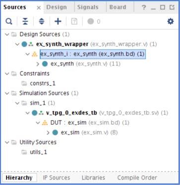
Table of Contents
       IP Facts

       Chapter 1: Overview
           Navigating Content by Design Process . . . . . . . . . . . . . . . . . . . . . . . . . . . . . . . . . . . . . . . . . . . . . . . . .                      5
           Feature Summary. . . . . . . . . . . . . . . . . . . . . . . . . . . . . . . . . . . . . . . . . . . . . . . . . . . . . . . . . . . . . . . . . .          5
           Applications . . . . . . . . . . . . . . . . . . . . . . . . . . . . . . . . . . . . . . . . . . . . . . . . . . . . . . . . . . . . . . . . . . . . . .    6
           Licensing and Ordering . . . . . . . . . . . . . . . . . . . . . . . . . . . . . . . . . . . . . . . . . . . . . . . . . . . . . . . . . . . . .            6

       Chapter 2: Product Specification
           Standards . . . . . . . . . . . . . . . . . . . . . . . . . . . . . . . . . . . . . . . . . . . . . . . . . . . . . . . . . . . . . . . . . . . . . . . .   7
           Performance. . . . . . . . . . . . . . . . . . . . . . . . . . . . . . . . . . . . . . . . . . . . . . . . . . . . . . . . . . . . . . . . . . . . . .      7
           Resource Utilization. . . . . . . . . . . . . . . . . . . . . . . . . . . . . . . . . . . . . . . . . . . . . . . . . . . . . . . . . . . . . . . .         9
           Core Interfaces and Register Space . . . . . . . . . . . . . . . . . . . . . . . . . . . . . . . . . . . . . . . . . . . . . . . . . . .                    9

       Chapter 3: Designing with the Core
           General Design Guidelines . . . . . . . . . . . . . . . . . . . . . . . . . . . . . . . . . . . . . . . . . . . . . . . . . . . . . . . . . 25
           Clock, Enable, and Reset Considerations . . . . . . . . . . . . . . . . . . . . . . . . . . . . . . . . . . . . . . . . . . . . . . 26
           System Considerations . . . . . . . . . . . . . . . . . . . . . . . . . . . . . . . . . . . . . . . . . . . . . . . . . . . . . . . . . . . . 26

       Chapter 4: Design Flow Steps
           Customizing and Generating the Core . . . . . . . . . . . . . . . . . . . . . . . . . . . . . . . . . . . . . . . . . . . . . . . .                         28
           Constraining the Core . . . . . . . . . . . . . . . . . . . . . . . . . . . . . . . . . . . . . . . . . . . . . . . . . . . . . . . . . . . . .             31
           Simulation . . . . . . . . . . . . . . . . . . . . . . . . . . . . . . . . . . . . . . . . . . . . . . . . . . . . . . . . . . . . . . . . . . . . . .      32
           Synthesis and Implementation . . . . . . . . . . . . . . . . . . . . . . . . . . . . . . . . . . . . . . . . . . . . . . . . . . . . . .                    32

       Chapter 5: Detailed Example Design
           Simulation Example Design . . . . . . . . . . . . . . . . . . . . . . . . . . . . . . . . . . . . . . . . . . . . . . . . . . . . . . . . . 34
           Synthesizable Example Design . . . . . . . . . . . . . . . . . . . . . . . . . . . . . . . . . . . . . . . . . . . . . . . . . . . . . . 37

       Chapter 6: Test Bench

       Appendix A: Verification, Compliance, and Interoperability
           Simulation . . . . . . . . . . . . . . . . . . . . . . . . . . . . . . . . . . . . . . . . . . . . . . . . . . . . . . . . . . . . . . . . . . . . . . 42

Video Test Pattern Generator v8.1                                                                                                Send Feedback
                                                                                                                                                                       3
PG103 August 6, 2021                                               www.xilinx.com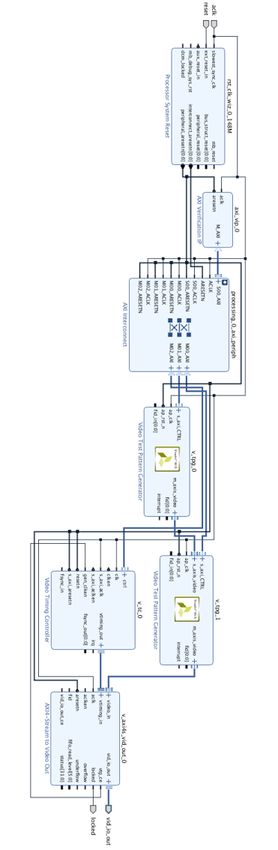
Hardware Testing. . . . . . . . . . . . . . . . . . . . . . . . . . . . . . . . . . . . . . . . . . . . . . . . . . . . . . . . . . . . . . . . . 42
           Interoperability . . . . . . . . . . . . . . . . . . . . . . . . . . . . . . . . . . . . . . . . . . . . . . . . . . . . . . . . . . . . . . . . . . 43

       Appendix B: Upgrading
           Migrating to the Vivado Design Suite. . . . . . . . . . . . . . . . . . . . . . . . . . . . . . . . . . . . . . . . . . . . . . . . . 44
           Upgrading in Vivado Design Suite. . . . . . . . . . . . . . . . . . . . . . . . . . . . . . . . . . . . . . . . . . . . . . . . . . . . 44

       Appendix C: Debugging
           Finding Help on Xilinx.com . . . . . . . . . . . . . . . . . . . . . . . . . . . . . . . . . . . . . . . . . . . . . . . . . . . . . . . . .             47
           Debug Tools . . . . . . . . . . . . . . . . . . . . . . . . . . . . . . . . . . . . . . . . . . . . . . . . . . . . . . . . . . . . . . . . . . . . .    48
           Hardware Debug . . . . . . . . . . . . . . . . . . . . . . . . . . . . . . . . . . . . . . . . . . . . . . . . . . . . . . . . . . . . . . . . .         49
           Vivado Synthesis Debug . . . . . . . . . . . . . . . . . . . . . . . . . . . . . . . . . . . . . . . . . . . . . . . . . . . . . . . . . . .             49

       Appendix D: Additional Resources and Legal Notices
           Xilinx Resources . . . . . . . . . . . . . . . . . . . . . . . . . . . . . . . . . . . . . . . . . . . . . . . . . . . . . . . . . . . . . . . . . .     50
           Documentation Navigator and Design Hubs . . . . . . . . . . . . . . . . . . . . . . . . . . . . . . . . . . . . . . . . . . .                            50
           References . . . . . . . . . . . . . . . . . . . . . . . . . . . . . . . . . . . . . . . . . . . . . . . . . . . . . . . . . . . . . . . . . . . . . .   51
           Revision History . . . . . . . . . . . . . . . . . . . . . . . . . . . . . . . . . . . . . . . . . . . . . . . . . . . . . . . . . . . . . . . . . .     51
           Please Read: Important Legal Notices . . . . . . . . . . . . . . . . . . . . . . . . . . . . . . . . . . . . . . . . . . . . . . . .                     52

Video Test Pattern Generator v8.1                                                                                                Send Feedback
                                                                                                                                                                    4
PG103 August 6, 2021                                               www.xilinx.com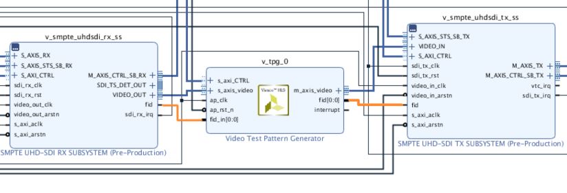
Chapter 1

Overview
       The Video Test Pattern Generator core generates video test patterns which can be used
       when developing video processing cores or bringing up a video system. The test patterns
       can be used to evaluate and debug color, quality, edge, and motion performance, debug
       and assess video system color, quality, edge, and motion performance of a system, or stress
       the video processing to ensure proper functionality.

       Navigating Content by Design Process
       Xilinx® documentation is organized around a set of standard design processes to help you
       find relevant content for your current development task. This document covers the
       following design processes:

       • Hardware, IP, and Platform Development: Creating the PL IP blocks for the hardware platform,
         creating PL kernels, subsystem functional simulation, and evaluating the Vivado timing, resource and
         power closure. Also involves developing the hardware platform for system integration. Topics in this
         document that apply to this design process include:
         ° Port Descriptions
         ° Register Space
         ° Customizing and Generating the Core
         ° Detailed Example Design

       Feature Summary
       The Video Test Pattern Generator core produces the following patterns in RGB, YUV 444,
       YUV 422, or YUV 420 video format. The YUV color space is based off of the ITU-R BT.601
       standard:

       •   Video input pass through
       •   Horizontal ramp
       •   Vertical ramp
       •   Temporal ramp
       •   Flat fields (red, green, blue, black and white)

Video Test Pattern Generator v8.1                                                     Send Feedback
                                                                                                                5
PG103 August 6, 2021                          www.xilinx.com
Chapter 1: Overview
• Combined vertical and horizontal ramp
• Color bars
• Color sweep
• Tartan bars
• DisplayPort
• Zone plate
• Cross hairs
• Cross hatch
• Solid box
• Motion effect for ramps, zone plate, and solid box
Applications
The horizontal and vertical ramps can be used to test system linearity. The temporal ramp
can be used to test the integrity of frame buffers that exist in the system. Flat fields are
useful for detecting possible chroma issues with video processing cores. Color bars and
tartan bars are used to verify the proper reproduction of color correction functions and the
color gamut of a monitor.
Licensing and Ordering
This Xilinx ® LogiCORE™ IP module is provided at no cost under the terms of the Xilinx Core
License Agreement. The module is shipped as part of the Vivado Design Suite.
For more information, visit the Video Test Pattern Generator product web page.
Information about other Xilinx LogiCORE IP modules is available at the Xilinx Intellectual
Property page. For information on pricing and availability of other Xilinx LogiCORE IP
modules and tools, contact your local Xilinx sales representative.
Video Test Pattern Generator v8.1 Send Feedback
6
PG103 August 6, 2021 www.xilinx.comChapter 2
Product Specification
Standards
The Video Test Pattern Generator core is compliant with the AXI4-Stream Video Protocol
and AXI4-Lite interconnect standards. Refer to the Video IP: AXI Feature Adoption section of
the Vivado AXI Reference Guide (UG1037) [Ref 1] for additional information.
Performance
The following sections detail the performance characteristics of the Video Test Pattern
Generator core. For full details about performance and resource utilization, visit the
Performance and Resource Utilization web page.
Maximum Frequencies
There are no IP specific restrictions on the maximum achievable clock frequency. The
restriction is dependent on if the design can meet timing or not. Meeting timing is
dependent on the clock frequency selected, and is impacted by resource utilization, tool
options, additional logic in the device and the version of tool used. For more information
see Xilinx timing closure documentation as well as the fabric data-sheets below. The
frequency ranges specified in these documents must be adhered to for proper transceiver
and core operation.
• Kintex UltraScale FPGAs Data Sheet: DC and AC Switching Characteristics (DS892)
[Ref 9]
• Virtex UltraScale FPGAs Data Sheet: DC and AC Switching Characteristics (DS893)
[Ref 10]
• Kintex-7 FPGAs Data Sheet: DC and AC Switching Characteristics (DS182) [Ref 11]
• Virtex-7 FPGAs Data Sheet: DC and AC Switching Characteristics (DS183) [Ref 12]
• Artix-7 FPGAs Data Sheet: DC and AC Switching Characteristics (DS181) [Ref 13]
• Zynq-7000 SoC (Z-7007S, Z-7012S, Z-7014S, Z-7010, Z-7015, and Z-7020) Data Sheet:
DC and AC Switching Characteristics (DS187) [Ref 14]
Video Test Pattern Generator v8.1 Send Feedback
7
PG103 August 6, 2021 www.xilinx.comChapter 2: Product Specification
• Zynq-7000 SoC (Z-7030, Z-7035, Z-7045, and Z-7100) Data Sheet: DC and AC Switching
Characteristics (DS191) [Ref 15]
• Kintex UltraScale+ FPGAs Data Sheet: DC and AC Switching Characteristics (DS922)
[Ref 16]
• Virtex UltraScale+ FPGA Data Sheet: DC and AC Switching Characteristics (DS923)
[Ref 17]
• Zynq UltraScale+ MPSoC Data Sheet: DC and AC Switching Characteristics (DS925)
[Ref 18]
• Zynq UltraScale+ RFSoC Data Sheet: DC and AC Switching Characteristics (DS926)
[Ref 19]
• Versal AI Core Series Data Sheet: DC and AC Switching Characteristics (DS957)
[Ref 20]
Throughput
The Video Test Pattern Generator core supports bidirectional data throttling between its
AXI4-Stream Slave and Master interfaces. If the slave side data source is not providing valid
data samples (s_axis_video_tvalid is not asserted), the core cannot produce valid
output samples after its internal buffers are depleted. Similarly, if the master side interface
is not ready to accept valid data samples (m_axis_video_tready is not asserted) the
core cannot accept valid input samples once its buffers become full.
If the master interface is able to provide valid samples (s_axis_video_tvalid is High)
and the slave interface is ready to accept valid samples (m_axis_video_tready is High),
typically the core can process and produce 1, 2, 4, or 8 pixels specified by Samples Per Clock
in GUI per AP_CLK cycle.
However, at the end of each scan line and frame the core flushes internal pipelines for seven
clock cycles, during which the s_axis_video_tready is de-asserted signaling that the
core is not ready to process samples.
When the core is processing timed streaming video (which is typical for most video
sources), the flushing periods coincide with the blanking periods therefore do not reduce
the throughput of the system.
When the core is processing data from a video source which can always provide valid data,
e.g. a frame buffer, the throughput of the core can be defined as follows:
ROWS COLS
R MAX = f APCLK × -------------- × ---------------------- × PPC Equation 2-1
ROWS COLS + 17
In numeric terms, 1080P/60 represents an average data rate of 124.4 MPixels/second
(1080 rows x 1920 columns x 60 frames / second x 1 pixel per clock), and a burst data rate
of 148.5 MPixels/sec.
To ensure that the core can process 124.4 MPixels/second, it needs to operate minimally at:
Video Test Pattern Generator v8.1 Send Feedback
8
PG103 August 6, 2021 www.xilinx.comChapter 2: Product Specification
ROWS COLS + 17 1080 1937
f APCLK = R MAX × -------------- × ----------------------- × PPC = 124.4 × ---------- × ---------- × 1 = 125.5 Equation 2-2
ROWS COLS 1080 1920
When operating on a streaming video source (i.e. not frame buffered data), the core must
operate minimally at the burst data rate, for example, 148.5 MHz for a 1080P60 video
source.
Resource Utilization
For details about resource utilization, visit Performance and Resource Utilization.
Core Interfaces and Register Space
Port Descriptions
The Video Test Pattern Generator core uses industry standard control and data interfaces to
connect to other system components. The following sections describe the various interfaces
available with the core. Figure 2-1 illustrates an I/O diagram of the TPG core. Some signals
are optional and not present for all configurations of the core. The AXI4-Lite interface is
always available while the AXI4-Stream slave interface is optional.
Video Test Pattern Generator v8.1 Send Feedback
9
PG103 August 6, 2021 www.xilinx.comChapter 2: Product Specification
X-Ref Target - Figure 2-1
s_axi_CTRL
s_axi_CTRL_ARADDR[7:0]
s_axi_CTRL_ARREADY
s_axi_CTRL_ARVALID
s_axi_CTRL_AWADDR[7:0]
s_axi_CTRL_AWREADY
s_axi_CTRL_AWVALID
s_axi_CTRL_BREADY
s_axi_CTRL_BRESP[1:0]
s_axi_CTRL_BVALID
m_axis_video
s_axi_CTRL_RDATA[31:0]
m_axis_video_TDATA[23:0]
s_axi_CTRL_RREADY
m_axis_video_TDEST[0:0]
s_axi_CTRL_RRESP[1:0]
m_axis_video_TID[0:0]
s_axi_CTRL_RVALID
m_axis_video_TKEEP[2:0]
s_axi_CTRL_WDATA[31:0]
m_axis_video_TLAST[0:0]
s_axi_CTRL_WREADY
m_axis_video_TREADY
s_axi_CTRL_WSTRB[3:0]
m_axis_video_TSTRB[2:0]
s_axi_CTRL_WVALID
m_axis_video_TUSER[0:0]
s_axi_video
m_axis_video_TVALID
s_axi_video_TVALID
interrupt
s_axi_video_TREADY
s_axi_video_TDATA[23:0] fid[0:0]
s_axi_video_TKEEP[2:0]
s_axi_video_TSTRB[2:0]
s_axi_video_TUSER[0:0]
s_axi_video_TLAST[0:0]
s_axi_video_TID[0:0]
s_axi_video_TDEST[0:0]
ap_clk
ap_rst_n
fid_in[0:0]
;
Figure 2-1: TPG Core Top-Level Signaling Interface
Common Interface Signals
Table 2-1 summarizes the signals which are either shared by, or not part of the dedicated
AXI4-Stream data or AXI4-Lite control interfaces.
Table 2-1: Common Interface Signals
Signal Name Direction Width Description
AP_CLK In 1 Video Core Clock
AP_RST_N In 1 Video Core active-Low reset
Video Test Pattern Generator v8.1 Send Feedback
10
PG103 August 6, 2021 www.xilinx.comChapter 2: Product Specification
Table 2-1: Common Interface Signals (Cont’d)
Signal Name Direction Width Description
INTERRUPT Out 1 Interrupt Request Pin
FID_IN In 1 Input Field ID port
FID Out 1 Field ID port
The AP_CLK and AP_RST_N and signals are shared between the core, the AXI4-Stream data
interfaces, and the AXI4-Lite control interface. The INTERRUPT pin is not supported and
reserved for future use.
AP_CLK
The AXI4-Stream and AXI4-Lite interfaces must be synchronous to the core clock signal
AP_CLK. All AXI4-Stream interface input signals and AXI4-Lite control interface input
signals are sampled on the rising edge of AP_CLK. All AXI4-Stream output signal changes
occur after the rising edge of AP_CLK.
AP_RST_N
The AP_RST_N pin is an active-low, synchronous reset input pertaining to both AXI-Lite and
AXI4-Stream interfaces. When AP_RST_N is set to 0, the core resets at the next rising edge
of AP_CLK.
FID_IN
The FID_IN is an active-Low pin used for pass-through mode, where in the Field ID input
to this block is passed to the FID port of the block.
FID
The FID is an active-Low pin used as Field ID for AXI4-Stream bus. It is used only for
interlaced video. When FID is set to 0, it is an even field and when FID is set to 1, it is an odd
field. This bit is sampled coincident with the SOF on the AXI4-Stream bus. If the signal is not
used (i.e. the progressive video input stream), the output must be set low.
Data Interface
The TPG core receives and transmits data using AXI4-Stream interfaces that implement a
video protocol as defined in the Video IP: AXI Feature Adoption section of the (UG761) AXI
Reference Guide [Ref 1].
Video Test Pattern Generator v8.1 Send Feedback
11
PG103 August 6, 2021 www.xilinx.comChapter 2: Product Specification
AXI4-Stream Signal Names and Descriptions
Table 2-2 describes the AXI4-Stream signal names and descriptions.
IMPORTANT: In Table 2-2, TotalDataWidth=data_width*number_of_components*samples_per_clock.
The three values correspond to Maximum Data Width, Number of Video Components and Samples Per
Clock in GUI, respectively. Refer to Chapter 4, Design Flow Steps for more information.
Table 2-2: AXI4-Stream Data Interface Signal Descriptions
Signal Name Direction Width Description
s_axis_video_tdata In (TotalDataWidth+7)/8*8 Input Video Data
s_axis_video_tvalid In 1 Input Video Valid Signal
s_axis_video_tready Out 1 Input Ready
s_axis_video_tuser In 1 Input Video Start Of Frame
s_axis_video_tlast In 1 Input Video End Of Line
s_axi_video_tstrb In s_axis_video tdata/8 Input video data strobe
indicates whether the content
of the associated byte of
TDATA is processed as a data
byte or a position byte
s_axi_video_tkeep In s_axis_video tdata/8 Input video byte qualifier that
indicates whether the content
of the associated byte of
TDATA is processed as part of
the data stream
s_axi_video_tid In 1 Input video data stream
identifier
s_axi_video_tdest In 1 Input video data routing
information
m_axis_video_tdata Out (TotalDataWidth+7)/8*8 Output Video Data
m_axis_video_tvalid Out 1 Output Valid
m_axis_video_tready In 1 Output Ready
m_axis_video_tuser Out 1 Output Video Start Of Frame
m_axis_video_tlast Out 1 Output Video End Of Line
Output video data strobe
indicates whether the content
m_axi_video_tstrb Out m_axis_video tdata/8 of the associated byte of
TDATA is processed as a data
byte or a position byte
Output video byte qualifier
that indicates whether the
m_axi_video_tkeep Out m_axis_video tdata/8 content of the associated byte
of TDATA is processed as part
of the data stream
Video Test Pattern Generator v8.1 Send Feedback
12
PG103 August 6, 2021 www.xilinx.comChapter 2: Product Specification
Table 2-2: AXI4-Stream Data Interface Signal Descriptions (Cont’d)
Signal Name Direction Width Description
Output video data stream
m_axi_video_tid Out 1
identifier
Output video data routing
m_axi_video_tdest Out 1
information
Video Data
The AXI4-Stream interface specification restricts TDATA widths to integer multiples of
8 bits. Therefore, any bit data must be padded with zeros on the MSB to form a N*8 bit wide
vector before connecting to s_axis_video_tdata. Padding does not affect the size of
the core.
Similarly, data on the TPG output m_axis_video_tdata is packed and padded to
multiples of 8 bits as necessary. Zero padding the most significant bits is only necessary for
10 and 12 bit wide data. Figure 2-2 through Figure 2-6 explain the pixel mapping of
AXI4-Stream interface with 2 pixels per clock and 10 bits per component configuration for
all supporting color formats. Zero padding (bits [63:60]) is not shown in the figures. Given
that TPG requires hardware configuration for 3 component video, the AXI4-Stream Subset
Converter is needed to hook up with other IPs of 2 component video interface in YUV 4:2:2
and YUV 4:2:0 color format. Refer to Appendix B, Upgrading and AXI4-Stream Video IP and
System Design Guide (UG934) [Ref 4] for more information.
X-Ref Target - Figure 2-2
Figure 2-2: Dual Pixels per Clock, 10 bits per Component Mapping for RGB
X-Ref Target - Figure 2-3
Figure 2-3: Dual Pixels per Clock, 10 bits per Component Mapping for YUV 4:4:4
X-Ref Target - Figure 2-4
Figure 2-4: Dual Pixels per Clock, 10 bits per Component Mapping for YUV 4:2:2
X-Ref Target - Figure 2-5
Figure 2-5: Dual Pixels per Clock, 10 bits per Component Mapping for YUV 4:2:0 Even Line
Video Test Pattern Generator v8.1 Send Feedback
13
PG103 August 6, 2021 www.xilinx.comChapter 2: Product Specification
X-Ref Target - Figure 2-6
Figure 2-6: Dual Pixels per Clock, 10 bits per Component Mapping for YUV 4:2:0 Odd Line
READY/VALID Handshake
A valid transfer occurs whenever READY, VALID, and AP_RST_N are High at the rising edge
of AP_CLK, as seen in Figure 2-7. During valid transfers, DATA only carries active video data.
Blank periods and ancillary data packets are not transferred through the AXI4-Stream video
protocol.
Guidelines on Driving s_axis_video_tvalid
Once s_axis_video_tvalid is asserted, no interface signals (except the TPG core
driving s_axis_video_tready) may change value until the transaction completes
(s_axis_video_tready, s_axis_video_tvalid, and AP_RST_N are high on the
rising edge of AP_CLK). Once asserted, s_axis_video_tvalid may only be de-asserted
after a transaction has completed. Transactions may not be retracted or aborted. In any
cycle following a transaction, s_axis_video_tvalid can either be de-asserted or remain
asserted to initiate a new transfer.
X-Ref Target - Figure 2-7
Figure 2-7: Example of READY/VALID Handshake, Start of a New Frame
Guidelines on Driving m_axis_video_tready
The m_axis_video_tready signal may be asserted before, during or after the cycle in
which the TPG core asserted m_axis_video_tvalid. The assertion of
m_axis_video_tready may be dependent on the value of m_axis_video_tvalid. A slave
that can immediately accept data qualified by m_axis_video_tvalid, should pre-assert
its m_axis_video_tready signal until data is received. Alternatively,
m_axis_video_tready can be registered and driven the cycle following VALID
assertion.
Video Test Pattern Generator v8.1 Send Feedback
14
PG103 August 6, 2021 www.xilinx.comChapter 2: Product Specification
RECOMMENDED: To minimize latency, your custom core's slave interface should drive READY
independently, or pre-assert READY.
Start of Frame Signals - m_axis_video_tuser0, s_axis_video_tuser0
The Start-Of-Frame (SOF) signal, physically transmitted over the AXI4-Stream TUSER0
signal, marks the first pixel of a video frame. The SOF pulse is 1 valid transaction wide, and
must coincide with the first pixel of the frame, as seen in Figure 2-7. The SOF signal serves
as a frame synchronization signal, which allows downstream cores to re-initialize, and
detect the first pixel of a frame. The SOF signal may be asserted an arbitrary number of
AP_CLK cycles before the first pixel value is presented on DATA, as long as a VALID is not
asserted.
End of Line Signals - m_axis_video_tlast, s_axis_video_tlast
The End-Of-Line (EOL) signal, physically transmitted over the AXI4-Stream TLAST signal,
marks the last pixel of a line. The EOL pulse is 1 valid transaction wide, and must coincide
with the last pixel of a scanline, as seen in Figure 2-8.
X-Ref Target - Figure 2-8
Figure 2-8: Use of EOL and SOF Signals
Control Interface
The AXI4-Lite register interface dynamically controls the behavior of the core. The AXI4-Lite
slave interface facilitates integrating the core into a processor system, or along with other
video or AXI4-Lite compliant IP, connected through AXI4-Lite interface to an AXI4-Lite
master. The core cannot be instantiated without the AXI4-Lite control interface.
AXI4-Lite Interface
The AXI4-Lite interface allows you to dynamically control parameters within the core. Core
configuration can be accomplished using an AXI4-Lite master state machine, or an
embedded Arm® or soft system processor such as MicroBlaze.
The TPG core can be controlled through the AXI4-Lite interface by using functions provided
by the driver in the Vitis software platform. Another method is performing read and write
Video Test Pattern Generator v8.1 Send Feedback
15
PG103 August 6, 2021 www.xilinx.comChapter 2: Product Specification
transactions to the TPG register space but should only be used when the first method is not
available.
Table 2-3: AXI4-Lite Interface Signals
Signal Name Direction Width Description
s_axi_CTRL_awvalid In 1 AXI4-Lite Write Address Channel Write Address Valid.
s_axi_CTRL_awready AXI4-Lite Write Address Channel Write Address
Out 1 Ready. Indicates DMA ready to accept the write
address.
s_axi_CTRL_awaddr In 8 AXI4-Lite Write Address Bus
s_axi_CTRL_wvalid In 1 AXI4-Lite Write Data Channel Write Data Valid.
s_axi_CTRL_wready AXI4-Lite Write Data Channel Write Data Ready.
Out 1
Indicates DMA is ready to accept the write data.
s_axi_CTRL_wdata In 32 AXI4-Lite Write Data Bus
s_axi_CTRL_bresp AXI4-Lite Write Response Channel. Indicates results of
Out 2
the write transfer.
s_axi_CTRL_bvalid AXI4-Lite Write Response Channel Response Valid.
Out 1
Indicates response is valid.
s_axi_CTRL_bready AXI4-Lite Write Response Channel Ready. Indicates
In 1
target is ready to receive response.
s_axi_CTRL_arvalid In 1 AXI4-Lite Read Address Channel Read Address Valid
s_axi_CTRL_arready Ready. Indicates DMA is ready to accept the read
Out 1
address.
s_axi_CTRL_araddr In 8 AXI4-Lite Read Address Bus
s_axi_CTRL_rvalid Out 1 AXI4-Lite Read Data Channel Read Data Valid
s_axi_CTRL_rready AXI4-Lite Read Data Channel Read Data Ready.
In 1
Indicates target is ready to accept the read data.
s_axi_CTRL_rdata Out 32 AXI4-Lite Read Data Bus
s_axi_CTRL_rresp AXI4-Lite Read Response Channel Response. Indicates
Out 2
results of the read transfer.
s_axi_CTRL_wstrb AXI4-Lite Write Strobe. Shows which bytes of the data
In 4
bus are valid and should be read by the Slave.
Video Test Pattern Generator v8.1 Send Feedback
16
PG103 August 6, 2021 www.xilinx.comChapter 2: Product Specification
Register Space
The core has 26 core-specific registers which allow you to dynamically control the
operation of the core. All registers have initial value of 0. Table 2-4 describes the register
names.
Table 2-4: Register Names and Descriptions
Address
(hex) Register Name Access Register Description
Type
BASEADDR +
0x0000 control R/W Bit 0: ap_start
Bit 1: ap_done
Bit 2: ap_idle
Bit 3: ap_ready
Bit 7: auto_restart
Others: reserved
0x0004 Global Interrupt Enable R/W Bit 0: Global Interrupt Enable
Others: reserved
This register is not used but reserved for future
use.
0x0008 IP Interrupt Enable Register R/W Bit 0: Channel 0 (ap_done)
Bit 1: Channel 1 (ap_ready)
Others: reserved
This register is not used but reserved for future
use.
0x000C IP Interrupt Status Register R Bit 0: Channel 0 (ap_done)
Bit 1: Channel 1 (ap_ready)
Others: reserved
This register is not used but reserved for future
use.
0x0010 active_height R/W Number of Active Lines per Frame
0x0018 active_width R/W Number of Active Pixels per Scanline
0x0020 background_pattern_id R/W Background pattern selection.
0x0028 foreground_pattern_id R/W Foreground pattern selection.
0x0030 mask_id R/W Color mask selection.
0x0038 motion_speed R/W How quickly the temporal features of the
supported test pattern change from frame to
frame
0x0040 color_format R/W Specify video color format
0x0048 cross_hair_hor R/W Horizontal cross hair location
0x0050 cross_hair_ver R/W Vertical cross hair location
0x0058 zplate_hor_cntl_start R/W Set a starting point based sinusoidal values for
the horizontal component
Video Test Pattern Generator v8.1 Send Feedback
17
PG103 August 6, 2021 www.xilinx.comChapter 2: Product Specification
Table 2-4: Register Names and Descriptions (Cont’d)
Address Access
(hex) Register Name Register Description
BASEADDR + Type
0x0060 zplate_hor_cntl_delta R/W Manipulates how quickly the horizontal
component changes
0x0068 zplate_ver_cntl_start R/W Set a starting point based sinusoidal values for
the vertical component
0x0070 zplate_ver_cntl_delta R/W Manipulates how quickly the vertical
component changes
0x0078 box_size R/W Size of the box in pixel x pixel
Bit [7:0]: Width of the box
Bit [15:8]: Height of the box
Since it is a NxN box, width and height are
same.
0x0080 box_color_red_y R/W Red, Y component value of the box
0x0088 box_color_green_u R/W Green, U component value of the box
0x0090 box_color_blue_v R/W Blue, V component value of the box
0x0098 enable_input R/W Indicate whether to make use of video stream
entering slave AXI4-Stream video interface.
Takes effect only when AXI4-Stream slave
interface is enabled.
0x00A0 pass_thru_start_x R/W Left boundary (inclusively) of pass through
window of video stream entering slave
AXI4-Stream video interface.
Takes effect only when AXI4-Stream slave
interface is enabled.
0x00A8 pass_thru_start_y R/W Right boundary (exclusively) of pass through
window of video stream entering slave
AXI4-Stream video interface.
Takes effect only when AXI4-Stream slave
interface is enabled.
0x00B0 pass_thru_end_x R/W Upper boundary (inclusively) of pass through
window of video stream entering slave
AXI4-Stream video interface.
Takes effect only when AXI4-Stream slave
interface is enabled.
0x00B8 pass_thru_end_y R/W Lower boundary (exclusively) of pass through
window of video stream entering slave
AXI4-Stream video interface.
Takes effect only when AXI4-Stream slave
interface is enabled.
0x00C0 dpDynamicRange R/W Dynamic range of DisplayPort color square in
RGB.
Takes effect only when DisplayPort color
square pattern is selected.
Video Test Pattern Generator v8.1 Send Feedback
18
PG103 August 6, 2021 www.xilinx.comChapter 2: Product Specification
Table 2-4: Register Names and Descriptions (Cont’d)
Address Access
(hex) Register Name Register Description
BASEADDR + Type
0x00C8 dpYUVCoef R/W Co-efficients of DisplayPort color square in
YUV.
Takes effect only when DisplayPort color
square pattern is selected.
0x00D0 field_id R/W Used to configure the Field ID port of this
block. Takes effect only for interlaced video
content. Default value is 0.
Bit 0: Progressive or Interlaced bit
0 - Progressive
1 - Interlaced
Bit 1: Polarity bit
0 - Low during Field 0 and High during Field 1
1 - High during Field 0 and Low during Field 1
Bit 2: Passthrough enable bit
0 - Generator mode
1 - Passthrough mode
Bit [31:3]: Reserved.
0x00D8 bck_motion_en R/W Enables or disables the horizontal motion of
the color bars pattern.
0x0 - Disable motion
0x1 - Enable motion
CONTROL (0x0000) Register
This register controls running of TPG. Bit 0 of the control register, ap_start, kicks off the
core from software. Writing ‘1’ to this bit start the core to generate a video frame. To set the
core in free running mode, bit 7 of this register, auto_restart, must be set to ‘1’. Bit 1-3
are not used now but reserved for future use.
ACTIVE_HEIGHT (0x0010) Register
The active_height register encodes the number of active scan lines per frame.
Supported values are between 64 and the value provided in the Maximum number of Rows
field in the GUI. To avoid processing errors, you should restrict values written to
active_height to the range supported by the core instance. While configuring the
interlaced resolution, the active_height should be configured as half (active_height/2).
ACTIVE_WIDTH (0x0018) Register
The active_width register encodes the number of active pixels per scan. Supported
values are 64 and the value provided in the Maximum number of Columns field in the GUI.
Video Test Pattern Generator v8.1 Send Feedback
19
PG103 August 6, 2021 www.xilinx.comChapter 2: Product Specification
To avoid processing errors, you should restrict values written to active_width to the
range supported by the core instance.
BACKGROUND_PATTERN_ID (0x0020) Register
The background_pattern_id register controls the majority of the pattern manipulations
that the TPG core produces.
This register controls which patterns are generated on the output of the core based on the
following values:
• 0x00 - Pass the video input straight through the video output
• 0x1 - Horizontal Ramp which increases each component (RGB or Y) horizontally by 1
• 0x2 -Vertical Ramp which increases each component (RGB or Y) vertically by 1
• 0x3 - Temporal Ramp which increases every pixel by a value set in the motion_speed
register for every frame.
• 0x4 - Solid red output
• 0x5 - Solid green output
• 0x6 - Solid blue output
• 0x7 - Solid black output
• 0x8 - Solid white output
• 0x9 - Color bars
• 0xA - Zone Plate output produces a ROM based sinusoidal pattern. This option has
dependencies on the motion_speed, zplate_hor_cntl_start,
zplate_hor_cntl_delta, zplate_ver_cntl_start and
zplate_ver_cntl_delta registers.
• 0xB - Tartan Color Bars
• 0xC - Draws a cross hatch pattern.
• 0xD - Color sweep pattern
• 0xE - A combined vertical and horizontal ramp
• 0xF - Black and white checker board
• 0x10 - Pseudorandom pattern
• 0x11 - DisplayPort color ramp
• 0x12 - DisplayPort black and white vertical lines
• 0x13 - DisplayPort color square
Video Test Pattern Generator v8.1 Send Feedback
20
PG103 August 6, 2021 www.xilinx.comChapter 2: Product Specification
In addition to setting the background_pattern_id register with the correct value, the
relative pattern category must be enabled when customizing IP to generate a desired
pattern during runtime. If some pattern categories are disabled, the TPG generates a pure
black screen when the background_pattern_id register is configured with a pattern in
a disabled category. For more information about the background pattern categorization,
refer to Chapter 4, Design Flow Steps.
FOREGROUND_PATTERN_ID (0x0028) Register
The foreground_pattern_id register controls the overlay pattern on top of background
pattern (100% opaque).
This register controls which overlay patterns based on the following values:
• 0x0 - No overlay pattern.
• 0x1 - Enables a moving box to be drawn over the video output. This option is
dependent on the box_size, box_color_red_y, box_color_green_u and
box_color_blue_v registers.
• 0x2 - Draws cross hairs one pixel in width on the output of the video. This feature
depends on the cross_hair_hor and cross_hair_ver register.
The foreground_pattern_id register takes effects only when the Foreground Patterns
parameter is enabled when customizing IP. If Foreground Patterns is disabled, no
foreground pattern appears regardless of which pattern is selected in
foreground_pattern_id register.
MASK_ID
The mask_id register only takes effect on RGB video format. It controls mask-out of a
particular color component.
• 0x0 - No masking
• 0x1 - Mask out the red component
• 0x2 - Mask out the green component
• 0x4 - Mask out the blue component
MOTION_SPEED (0x0038) Register
This register cause the ramps, box and zone plate to increment by that value every frame.
COLOR_FORMAT (0x0040) Register
This register specifies the video format that the TPG core produces. It should match the
input video format if AXI4-Stream slave interface is enabled in the GUI.
Video Test Pattern Generator v8.1 Send Feedback
21
PG103 August 6, 2021 www.xilinx.comChapter 2: Product Specification
• 0x0 - RGB video format
• 0x1 - YUV 444 video format
• 0x2 - YUV 422 video format
• 0x3 - YUV 420 video format
CROSS_HAIR_HOR (0x0048) Register
The column of the frame that has the horizontal line of the cross hairs. This register takes
effect only when Foreground Pattern (0x0020) is set to 2.
CROSS_HAIR_VER (0x0050) Register
The row of the frame that has the vertical line of the cross hairs. This register takes effect
only when Foreground Pattern (0x0020) is set to 2.
ZPLATE_HOR_CNTL_START (0x0058) Register
The zplate_hor_cntl_start register sets how widely spaced the horizontal component
of a sine function are placed together. The larger the number, the more narrow the spacing.
ZPLATE_HOR_CNTL_DELTA (0x0060) Register
This register controls the horizontal component speed by manipulating the indexing into
the ROM table that contains the sinusoidal values.
ZPLATE_VER_CNTL_START (0x0068) Register
The zplate_ver_cntl_start register sets the vertical component starting point in the
ROM table that contains the sinusoidal values.
ZPLATE_VER_CNTL_DELTA (0x0070) Register
This register controls the vertical component speed by manipulating the indexing into the
ROM table that contains the sinusoidal values.
BOX_SIZE (0x0078) Register
The BOX_SIZE register defines the size of overlying box, where N represents NxN size of
box. It is NxN for progressive video and Nx2N for interlaced video. The size of the box has
to be set smaller than the frame size that is set in the active_height and
active_width register. This register relies on value of foreground pattern (0x0020). If
foreground pattern register is 1, the box is enabled; otherwise the box is disabled.
Video Test Pattern Generator v8.1 Send Feedback
22
PG103 August 6, 2021 www.xilinx.comChapter 2: Product Specification
BOX_COLOR_RED_Y (0x0080) Register
Red, Y (for YUV mode) color component of the box.
BOX_COLOR_GREEN_U (0x0088) Register
Green, U (for YUV mode) color component of the box.
BOX_COLOR_BLUE_V (0x0090) Register
Blue, V (for YUV mode) color component of the box.
ENABLE_INPUT (0x0098) Register
The enable_input register indicate whether to make use of video stream entering slave
AXI4-Stream video interface.
• 0x0 - Ignore the input video stream. The IP works the same way as AXI4-Stream slave is
disabled although it has s_axi_video interface and connection.
• 0x1 - Make use of input video stream.
PASS_THRU_START_X (0x00a0) Register
The TPG IP can pass through part of input video stream inside an upright rectangle straight
through video output as part of background pattern when AXI4-Stream slave interface is
enabled. The pass-through window takes precedence over the regular background pattern
at the same location. The pass_thru_start_x register specifies the left boundary
(inclusively) of pass through window.
PASS_THRU_START_Y (0x00a8) Register
The pass_thru_start_y register specifies the right boundary (exclusively) of pass
through window.
PASS_THRU_END_X (0x00b0) Register
The pass_thru_end_x register specifies the upper boundary (inclusively) of pass through
window.
PASS_THRU_END_Y (0x00b8) Register
The pass_thru_end_y register specifies the lower boundary (exclusively) of pass through
window.
Video Test Pattern Generator v8.1 Send Feedback
23
PG103 August 6, 2021 www.xilinx.comChapter 2: Product Specification
IMPORTANT: Note that in pass through window registers, the left and top boundaries are inclusive
while the right and bottom are exclusive. For example, to pass though a top-left 720P window, these
four registers should be set to (0, 0, 1280, 720), respectively, rather than (0, 0, 1279, 719).
dpDynamicRange (0x00c0) Register
This register specifies the dynamic range of DisplayPort color square definition in RGB. The
default value is VESA.
• 0x0 - VESA
• 0x1 - CEA
dpYUVCoef (0x00c8) Register
This register specifies the coefficients of DisplayPort color square definition in YUV.
• 0x0 - coefficients 601
• 0x1 - coefficients 709
field_id (0x00d0) Register
This register helps in configuration of interlaced video content.
• 0x0 - Progressive mode
• 0x1 - Interlaced mode
• 0x2 - Progressive mode with reverse polarity
• 0x3 - Interlaced mode with reverse polarity
• 0x4 - Passthrough mode
bck_motion_en (0x00d8) Register
This register helps in enabling and disabling the horizontal motion of the Color Bars
Pattern.
• 0x0 - Disable Motion
• 0x1 - Enable Motion
Video Test Pattern Generator v8.1 Send Feedback
24
PG103 August 6, 2021 www.xilinx.comChapter 3
Designing with the Core
General Design Guidelines
The TPG core provides a variety of test patterns to test a video processing core or system by
feeding known patterns through the Video over AXI4-Stream interface.
The core accepts video data provided through an AXI4-Stream slave interface (when
configured with a slave interface), outputs pixels through an AXI4-Stream master interface,
and can be controlled through an AXI4-Lite interface. The TPG block cannot change the
input/output image sizes, the input and output pixel clock rates, or the frame rate.
A typical example design of the Test Pattern Generator core is shown in Figure 3-1. For more
information about the Video Test pattern generator Example Design, refer to Chapter 5,
Detailed Example Design.
X-Ref Target - Figure 3-1
Figure 3-1: Example System with Video Test Pattern Generator Core
Video Test Pattern Generator v8.1 Send Feedback
25
PG103 August 6, 2021 www.xilinx.comChapter 3: Designing with the Core
Clock, Enable, and Reset Considerations
AP_CLK
The master and slave AXI4-Stream video interfaces use the AP_CLK clock signal as their
shared clock reference, as shown in Figure 3-2.
X-Ref Target - Figure 3-2
Video IP “Source” Video IP “Sink”
Video Test Pattern Generator
s_axis_video_tdata m_axis_video_tdata s_axis_video_tdata m_axis_video_tdata s_axis_video0_tdata
s_axis_video_tvalid m_axis_video_tvalid s_axis_video_tvalid m_axis_video_tvalid s_axis_video0_tvalid
s_axis_video_tready m_axis_video_tready s_axis_video_tready m_axis_video_tready s_axis_video0_tready
s_axis_video_tlast m_axis_video_tlast s_axis_video_tlast m_axis_video_tlast s_axis_video0_tlast
s_axis_video_tuser m_axis_video_tuser s_axis_video_tuser m_axis_video_tuser s_axis_video0_tuser
ap_clk ap_clk ap_clk
ap_rst_n ap_rst_n ap_rst_n
Figure 3-2: Example of AP_CLK Routing in an ISP Processing Pipeline
The AXI4-Lite interface also uses the AP_CLK pin as its clock source. The AP_CLK pin is
shared between the AXI4-Lite and AXI4-Stream interfaces.
AP_RST_N
The Video Test Pattern Generator core has only a hardware reset option - the AP_RST_N
pin. No software reset option is available.
The external reset pulse needs to be held for 16 or more AP_CLK cycles to reset the core.
The AP_RST_N signal is synchronous to the AP_CLK clock domain. The AP_RST_N signal
resets the entire core including the AXI4-Lite and AXI4-Stream interfaces.
System Considerations
The Video Test Pattern Generator IP core must be configured for the actual input image
frame-size to operate properly. To gather the frame size information from the image video
stream, it can be connected to the Video In to AXI4-Stream input and the Video Timing
Controller. The timing detector logic in the Video Timing Controller gathers the video
timing signals. The AXI4-Lite control interface on the Video Timing Controller allows the
system processor to read out the measured frame dimensions, and program all downstream
cores, such as the TPG, with the appropriate image dimensions.
Video Test Pattern Generator v8.1 Send Feedback
26
PG103 August 6, 2021 www.xilinx.comChapter 3: Designing with the Core
When the Video Test Pattern Generator switches from Pass Through mode to generating a
test pattern, the TPG uses an internal timing mechanism to produce Video over
AXI4-Stream timing information.
Programming Sequence
All TPG processing parameters other than image size can be changed dynamically and the
change is picked up immediately. If the image size needs to be changed on the fly or the
entire system needs to be restarted, it is recommended that pipelined Xilinx® IP video cores
are disabled/reset from system output towards the system input, and programmed/enabled
from system output to system input.
Note: A reset to the IP is required when the TPG is switched from passthrough mode to generate
mode or from generate mode to passthrough mode.
Video Test Pattern Generator v8.1 Send Feedback
27
PG103 August 6, 2021 www.xilinx.comChapter 4
Design Flow Steps
This chapter describes customizing and generating the core, constraining the core, and the
simulation, synthesis and implementation steps that are specific to this IP core. More
detailed information about the standard Vivado® design flows and the IP integrator can be
found in the following Vivado Design Suite user guides:
• Vivado Design Suite User Guide: Designing IP Subsystems using IP Integrator (UG994)
[Ref 8]
• Vivado Design Suite User Guide: Designing with IP (UG896) [Ref 3]
• Vivado Design Suite User Guide: Getting Started (UG910) [Ref 6]
• Vivado Design Suite User Guide: Logic Simulation (UG900) [Ref 7]
Customizing and Generating the Core
You can customize the IP for use in your design by specifying values for the various
parameters associated with the IP core using the following steps:
1. Select the IP from the IP catalog.
2. Double-click on the selected IP or select the Customize IP command from the toolbar or
popup menu.
For details, see the sections, “Working with IP” and “Customizing IP for the Design” in the
Vivado Design Suite User Guide: Designing with IP (UG896) [Ref 3] and the “Working with the
Vivado IDE” section in the Vivado Design Suite User Guide: Getting Started (UG910) [Ref 6].
If you are customizing and generating the core in the Vivado IP Integrator, see the Vivado
Design Suite User Guide: Designing IP Subsystems Using IP Integrator (UG994) [Ref 8] for
detailed information. IP Integrator might auto-compute certain configuration values when
validating or generating the design. To check whether the values do change, see the
description of the parameter in this chapter. To view the parameter value you can run the
validate_bd_design command in the Tcl console.
Note: Figures in this chapter are illustrations of the Vivado IDE. This layout might vary from the
current version.
Video Test Pattern Generator v8.1 Send Feedback
28
PG103 August 6, 2021 www.xilinx.comChapter 4: Design Flow Steps
Interface
The Xilinx® Video Test Pattern Generator (TPG) core is easily configured to meet your
specific needs through the Vivado Design Suite. This section provides a quick reference to
parameters that can be configured at generation time.
X-Ref Target - Figure 4-1
Figure 4-1: Customize IP Screen
The screen displays a representation of the IP symbol on the left side, and the parameter
assignments on the right side, which are described as follows:
• Component Name: The component name is used as the base name of output files
generated for the module. Names must begin with a letter and must be composed
from characters: a to z, 0 to 9 and “_”.
• Samples Per Clock: Specifies the number of pixel processed per clock cycle. Permitted
values are 1, 2, 4, and 8 samples per clock. This parameter determines IP's throughput.
The more samples per clock, the larger throughput it provides. The larger throughput
always needs more hardware resources.
• Maximum Data Width: Specifies the bits per component of input samples when the
core is in pass-through mode and defines the size (bits per component) of the
Video Test Pattern Generator v8.1 Send Feedback
29
PG103 August 6, 2021 www.xilinx.comChapter 4: Design Flow Steps
generated stream when in generator mode. Permitted values are 8, 10, 12 and 16 bits.
This parameter should match the Video Component Width of the video IP core
connected to the master and slave AXI-Stream video interfaces. This value is static and
is not configurable during runtime.
• Maximum Number of Columns: Specifies maximum video columns/pixels the IP core
could produce at runtime. Any video width that is less than Maximum Number of
Columns can be programmed through AXI4-Lite control interface without regenerating
core.
• Maximum Number of Rows: Specifies maximum video rows/lines the IP core could
produce at runtime. Any video height that is less than Maximum Number of Rows can
be programmed through AXI4-Lite control interface without regenerating core.
• Enable AXI4-Stream Slave interface: When checked, the core can feed the video input
stream through. When unchecked, the core can operate without a video input stream
producing only the test patterns that the TPG can generate.
• Solid Color: Specifies whether to enable solid color patterns. Check the box when solid
color patterns are desired during runtime; otherwise uncheck the box to save resources
and improve timing performance. The solid color category contains solid red (0x04),
solid green (0x05), solid blue (0x06), solid black (0x07), and solid white (0x08) described
under background_pattern_id register in Chapter 2, Product Specification.
• Ramp Pattern: Specifies whether to enable ramp patterns. Check the box when ramp
pattern are desired during runtime; otherwise uncheck the box to save resources and
improve timing performance. This category contains horizontal ramp (0x1), vertical
ramp (0x2), temporal ramp (0x3), and combined vertical and horizontal ramp (0xE).
• Color Bar: Specifies whether to enable color bar patterns. Check the box when color
bar patterns are desired during runtime; otherwise uncheck the box to save resources
and improve timing performance. This category has color bars (0x9), Tartan color bars
(0xB), cross hatch (0xC) and black and white checker board (0xF).
• DisplayPort: Specifies whether to enable DisplayPort patterns. Check the box when
DisplayPort patterns are desired during runtime; otherwise uncheck the box to save
resources and improve timing performance. The DisplayPort color ramp (0x11),
Displayport black and white vertical lines (0x12) and DisplayPort color square (0x13)
are among this category.
• Color Sweep: Specifies whether to enable color sweep pattern. Check the box when
color sweep pattern is desired during runtime; otherwise uncheck the box to save
resources and improve timing performance. Color sweep (0xD) is the only pattern is
this category.
• Zone Plate: Specifies whether to enable zone plate pattern. Check the box when zone
plate pattern is desired during runtime; otherwise uncheck the box to save resources
and improve timing performance. Zone Plate (0xA) is the only pattern is this category.
Video Test Pattern Generator v8.1 Send Feedback
30
PG103 August 6, 2021 www.xilinx.comChapter 4: Design Flow Steps
• Foreground Patterns: Specifies whether to enable foreground patterns. Check the box
when foreground patterns are desired during runtime; otherwise uncheck the box to
save resources and improve timing performance.
Output Generation
For details, see “Generating IP Output Products” in the Vivado Design Suite User Guide:
Designing with IP (UG896) [Ref 3].
Constraining the Core
This section contains information about constraining the core in the Vivado Design Suite.
Required Constraints
The only constraints required are clock frequency constraints for the core clock, ap_clk.
Paths from AXI4-Lite signals should be constrained with a set_false_path, causing
setup and hold checks to be ignored for AXI4-Lite signals. These constraints are provided in
the XDC constraints file included with the core.
Device, Package, and Speed Grade Selections
This section is not applicable for this IP core.
Clock Frequencies
This section is not applicable for this IP core.
Clock Management
This section is not applicable for this IP core.
Clock Placement
This section is not applicable for this IP core.
Banking
This section is not applicable for this IP core.
Video Test Pattern Generator v8.1 Send Feedback
31
PG103 August 6, 2021 www.xilinx.comChapter 4: Design Flow Steps
Transceiver Placement
This section is not applicable for this IP core.
I/O Standard and Placement
This section is not applicable for this IP core.
Simulation
For comprehensive information about Vivado simulation components, as well as
information about using supported third party tools, see the Vivado Design Suite User
Guide: Logic Simulation (UG900) [Ref 7].
Synthesis and Implementation
This section contains information about synthesis and implementation in the Vivado Design
Suite. For details about synthesis and implementation, see “Synthesizing IP” and
“Implementing IP” in the Vivado Design Suite User Guide: Designing with IP (UG896) [Ref 3].
Video Test Pattern Generator v8.1 Send Feedback
32
PG103 August 6, 2021 www.xilinx.comChapter 5
Detailed Example Design
This chapter provides two example systems that include the Video Test Pattern Generator
core. One is simulation example design and the other one is synthesizable example design.
Important system-level aspects when designing with the Video Test Pattern Generator are
highlighted in example designs, including:
• Video test pattern generator usage in AXI-Stream Slave enable and disable mode.
• Typical usage of video test pattern generator in conjunction with other cores and AXI
master.
• Configuration of video test pattern generation registers on the fly.
Note: The example project is only available on Xilinx KC705 evaluation board.
Table 5-1: Example Design Support
Development Board Additional Hardware Processor Topology
KC705 N/A MicroBlaze Generator or Passthrough
ZCU102 N/A psu_cortexa53_0 Generator or Passthrough
VCK190 N/A CIPS Generator or Passthrough
To open the example project, perform following:
1. Select the Video Test Pattern Generator IP from IP Catalog.
2. Double-click on the selected IP or right-click the IP and select Customize IP from the
menu.
3. Configure the build-time parameters in the Customize IP window and click OK. The
Vivado IDE generates an example design matching the build-time configuration.
4. In the Generate Output Products window, select Generate or Skip. If Generate is
selected, the IP’s output products are generated after a brief moment.
5. Right-click TPG in Sources panel and select Open IP Example Design from the menu.
6. In the Open IP Example Design window, select example project directory and click OK.
The Vivado software then runs automation to generate example design in selected
directory.
Video Test Pattern Generator v8.1 Send Feedback
33
PG103 August 6, 2021 www.xilinx.comChapter 5: Detailed Example Design
The generated project contains two example designs. Figure 5-1 shows the Source panel of
the example project. Synthesizable example block design, along with top-level file, resides
in Design Sources catalog. Corresponding constraint file is also provided for the
synthesizable example design. Simulation example design files (including block design file,
SystemVerilog test bench and another task file) are under Simulation Sources.
X-Ref Target - Figure 5-1
Figure 5-1: Example Project Source Panel
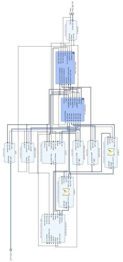
Simulation Example Design
The simulation example design contains two video test pattern generator cores. v_tpg_0 is
configured to AXI-Stream Slave disable mode while v_tpg_1 is in AXI-Stream Slave enable
mode. This example design shows conjunction of TPG core with other cores and AXI
Verification IP (VIP) core through AXI interconnect.
AXI VIP acts as AXI master in the system to drive TPG cores and Video Timing Controller
core. It configures width, height, pattern and other registers of TPG cores. Timing
parameters of Video Timing Controller core are also been configured by AXI VIP core. After
all configurations are performed, AXI VIP core starts TPG cores and Video Timing Controller
core. Because this design runs RTL simulation, large video frame can take a long time. It's
recommended to run a small video size for this example design. Width and height value can
be changed in simulation test bench v_tpg_0_exdes_tb.sv file.
Video Test Pattern Generator v8.1 Send Feedback
34
PG103 August 6, 2021 www.xilinx.comChapter 5: Detailed Example Design
The v_tpg_0 core is in free-running mode after kickoff, and generates video stream pixels
at clock rate of ap_clk.
The v_tpg_1 core receives video frames from AXI-Stream Slave interface and generates
video output.
AXI4-Stream to Video Out core, working with Video Timing Controller, interfaces from the
AXI4-Stream interface implementing a Video Protocol to a video source (parallel video data,
video syncs, and blanks).
The test bench checks the output port locked from the AXI4-Stream to Video Out core. The
locked port indicates that the output timing is locked to the output video. The test bench
indicates that the test completed successfully if video lock is successfully detected.
Video Test Pattern Generator v8.1 Send Feedback
35
PG103 August 6, 2021 www.xilinx.comYou can also read