POC (PROOF OF CONCEPT) FOR PERFORMANCE MONITORING PLATFORM OF CONTAINER TERMINALS
←
→
Page content transcription
If your browser does not render page correctly, please read the page content below
Journal of
           Marine Science
           and Engineering

Article
PoC (Proof of Concept) for Performance Monitoring
Platform of Container Terminals
Nam Kyu Park 1, * and Jung Hun Lee 2
 1    Department of International Logistics, Tongmyong University, Busan 48520, Korea
 2    Busan Development Institute, 955, Jungang-dearo, Busanjin-gu, Busan 47210, Korea; ljh4139@bdi.re.kr
 *    Correspondence: nkpark@tu.ac.kr; Tel.: +82-010-3575-1004

 Received: 28 October 2020; Accepted: 16 November 2020; Published: 28 November 2020

 Abstract: The purpose of this study is to prove the concept of the performance monitoring system of
 container terminals. PoC (Proof of Concept) is a realization of a certain method or idea in order to
 demonstrate its feasibility. The port authorities, such as government or local authority, are continually
 checking the performance of the terminals they invested in and want to reflect it in the development
 policy. They also want to increase competitiveness by checking performance levels, such as port
 handling volume, calling ships, resource utilization, and congestion. PPI (Port performance indicators)
 are classified into four categories: output (production), productivity, utilization, and service. In this
 study, 15 monitoring indicators for each stage by dividing the process from the ship’s entry to departure
 are defined. Four indicators, such as ship waiting ratio at anchorage, berth occupancy, storage
 occupancy, and truck turnaround time, are selected as PoC of monitoring platform. In addition,
 a method of collecting, processing, and expressing data on these four indicators in real time is
 presented. There are three steps to create PPI on monitoring platform. The information required
 for PPI is to be collected from the Port-MIS (Management Information System) and TOS (Terminal
 Operating System) databases. Second, the collected data from external entities are stored into the
 database after verification and classification. Third, descriptive PPI, predictive PPI are generated
 based on the input data. This study provides a 4-tier framework from the conceptual platform with
 the key elements of data presentation, data process and data interface and middleware. As a result of
 the study, it is proved to select monitoring indicators, define external entities, define internal elements
 of the system, develop systems, and present indicator results. However, in the process of collecting
 data outside the system, we have found there is confidential data of individual terminals. To this end,
 it is important to establish a mutual cooperation system for data collection.

 Keywords: container terminal operation; port performance indicator; port monitoring platform

1. Introduction
      The characteristics of smart port is that the cycle of decision making is shortened by going through
the stages of data collection, analyzing, diagnosis, prediction and prescription [1]. The port authorities
have invested a large amount of investment to construct and operate a container terminal, but it has
not provided the monitoring platform to evaluate the performance of the terminal in the perspective
of Port Authority. This paper is to prove whether the monitoring platform is useful for performance
improvement by constructing a prototype [2] of port performance monitoring system.
      PoC (Proof of Concept) is a realization of a certain method or idea in order to demonstrate
its feasibility [3]. Port Authority including central or local government is continually checking the
performance of the terminal they invested in and want to reflect it in the development policy. They also
want to increase competitiveness by checking performance levels, such as cargo volume, calling ships,
resource utilization, and congestion.

J. Mar. Sci. Eng. 2020, 8, 971; doi:10.3390/jmse8120971                             www.mdpi.com/journal/jmse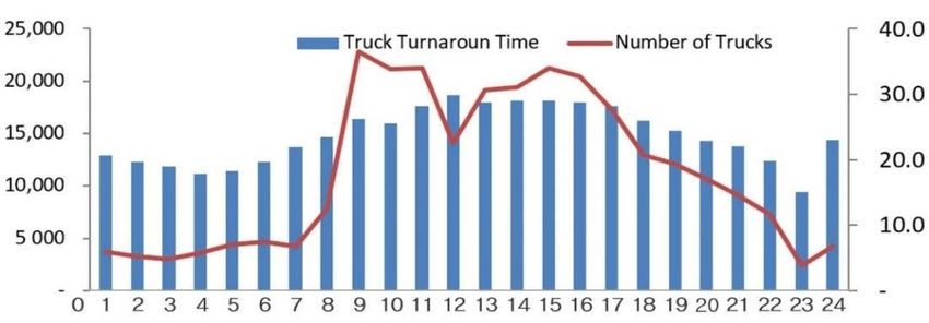
J. Mar. Sci. Eng. 2020, 8, 971                                                                        2 of 20

      In order to immediately check the terminal performance, data must be input from individual
terminals in real time. This study start defining the monitoring indicators for each stage by dividing
the process from the ship’s entry to departure. We will develop a prototype of performance monitoring
platform to conceptually prove that it works as intended.
      As monitoring system is to be used by Ministry of Ocean and Fishery (MOF), Port Authority (PA)
and TOC (Terminal Operating Company) [4], it is necessary to analysis the relationship between source
data as external entities and the system as internal system. The process, ERA (Entity Relationship
Attribute) diagram and User View for creating PPI (Port Performance Indicator) must be designed
during implementing PoC.
      The definition and calculation formula of PPI has been studied by researchers and practitioners,
but there is no systematic approach to creating them for Port Authority in real time as a platform
type. The contribution of this paper is that the existing PPI was systematically classified and a new
PPI, such as truck turnaround time, was proposed. Furthermore, it proved a system that can produce
the defined PPI in real time by linking with the existing Terminal Operating System (TOS) and Port
Management Information System (MIS).
      Based on PPI, the paper discusses what data to collect, how to build a database, what type of
system architecture does it have as a tool of PoC. Source data is collected from MOF and TOC and the
output of monitoring platform is provided to MOF, PA, TOC, shipping company, etc. The data used in
this study are batch data and have limitations in real-time data monitoring. This paper consists of six
steps as follows.

(1)    First step is to define a PPI to understand the container terminal’s performance. PPI is defined
       according to the criteria of output, productivity, utilization and service.
(2)    Second step is to collect data from TOC. This is the data regarding to berth facility and activity,
       yard facility and activity during one year (refer to Appendix A Tables A1–A4). For data collection.
       There are 19 terminals for collecting data within Busan port, Incheon port, Gwangyang port,
       Pyeongtaek port, and Ulsan port.
(3)    Third step is to collect data from Port-MIS of MOF. Data consists of port code, port name, call sign,
       number of arrivals by year, ship name, facility code, facility name, port facility use purpose code,
       port facility use purpose name, start date and time, end of use date and time (refer Appendix A
       Tables A5 and A6).
(4)    Fourth step is to design the architecture of the monitoring platform. In this study, four components:
       data presentation, data process and data interface and middleware are designed.
(5)    Fifth step is to design and implement database. Then, the collected data is input into the database
       in order to produce the result.
(6)    Sixth step is to design the PPIs’ presentation format which is suitable for performance management
       as user view.
(7)    Seventh step is to create a program that connects the database and graphic tool, SQL (Structured
       Query Language), web program language.

2. Methods
     To develop a PPI monitoring platform, the development methodology, such as waterfall, spiral,
agile rapid development, software prototyping, and incremental, is required [5]. In this study,
rapid prototyping will be used for monitoring platform development because prototyping can improve
the quality of requirements and specifications provided to developers [6]. This refers to the creation of
a model that will eventually be discarded rather than becoming part of the final delivered software.
After preliminary requirements gathering is accomplished, a simple working model of the system
is constructed to visually show the users what their requirements may look like when they are
implemented into a finished system [7]. The prototype is developed through the following procedure
(refer Table 1).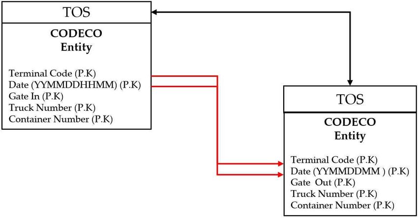
J. Mar. Sci. Eng. 2020, 8, 971                                                                                3 of 20

                                     Table 1. Research steps and results.

          Research Steps.                         Description                              Findings
      PPI (Port Performance      Selected 14 PPIs for monitoring that PA (Port          Figures 1 and 2
       Indicator) Definition              Authority) are interested in                      Table 3
      User Query Definition           User queries are defined using PPI                    Table 3
                                   Selecting 19 terminals for collecting data,       Appendix A Table A1
           Data Collection
                                             including Busan Port                         Table 4
                                   Design of data items related to terminal
       Data Item and Format        specifications, ship entry and exit, cargo
                                                                                   Appendix A Tables A1–A5
               Design            handling, utilization of equipment, and truck
                                             entry and exit records
      Design of Business Flow        Defines external entities and internal
                                                                                           Figure 3
             Diagram                      components of the system.
                                     Design system internal components
         Design of System
                                 consisting of data presentation, data process             Figure 4
           Architecture
                                     and data interface and middleware.
                                  Design ERD (Entity Relationship Diagram)
        Entity Relationship
                                 for 4 representative PPIs in the ship entry and     Figure 5, 7, 9, and 11
         Diagram Design
                                               departure process.
                                     Four PPIs were programmed using a
         Programming for
                                       database, graphic tool, and web               Figure 6, 8, 10 and 12
            Prototype
                                           programming language.

(1)    First is to identify basic requirements: Determine basic requirements including the input and
       output information desired. Details, such as security, can typically be ignored. In this step,
       the PPIs to be monitored are defined. PPI selection is defined by referring to previous studies and
       the procedure of call ship and cargo in port. After selection of PPI, they are confirmed through
       consultation with officials of PA.
(2)    Second is to develop initial prototype: After the initial prototype is developed that includes
       only user interfaces and database interface. In this step, the PPI defined in step (1) is created.
       Here, proof of concept is attempted for four of the PPIs. The four PPIs are representative of
       ship entry and departure processes, and consist of ship waiting ratio, berth occupancy, storage
       utilization, and truck turnaround time.
(3)    Third is to review the prototype: The customers, including end-users, examine the prototype and
       provide feedback on potential additions or changes.
(4)    Fourth is to revise and enhance the prototype: Using the feedback both the specifications and the
       prototype can be improved. Negotiation about what is within the scope of the contract/product
       may be necessary. If changes are introduced, then a repeat of steps (3) and (4) may be needed.
       The result is shown on confidential web address [8].

3. Results

3.1. PPI for Ship Arrival—Unloading—Stocking—Ship Depart
      To identify the PPI for monitoring ship activity, the ship’s arrival-berthing-loading/unloading-
departure process should be described in Figure 1. When the ships arrive at port, the berth availability
is to be identified before berthing. Especially, the berth scheduling should be checked in advance to
ensure the availability of the berth. In order to alleviate potential congestion issues and avoid the cargo
delivery delays to the end customer, TOC should improve the effectiveness of the terminal operations
by monitoring PPI [9]. TOC strive to achieve rapid unloading and loading as ships become larger
container vessels, which corresponds to a reduction of the time in port for the vessels [10]. To make
J. Mar. Sci. Eng. 2020, 8, 971 4 of 20
ships at Yangsan Port congested and shorten unloading time, Double-Line Shipping Mooring (DLSM)
mode in enforced [11]. For monitoring port capacity, BAP (Berth Allocation Problem) must be solved
in extensive simulations, needed to account for ship traffic and handling times uncertainties4 [12].
J. Mar. Sci. Eng. 2020, 8, x FOR PEER REVIEW of 18
Efficient seaside operations are critical for TOC performance, as disruptions in the seaside operations
may significantly
operations delay service
may significantly of the
delay arriving
service vessels
of the [13]. vessels
arriving It is an [13].
important
It is anissue to measure
important issuetheto
performance of the berth and
measure the performance of prepare
the berthcountermeasures due to the enlargement
and prepare countermeasures due to theof ships and the increase
enlargement of ships
in cargo
and the volume.
increase The solution
in cargo affectsThe
volume. the operational performance
solution affects of the whole
the operational terminal container
performance of the whole[14].
If all berths
terminal are occupied
container byberths
[14]. If all ships, are
then a ship has
occupied to wait
by ships, at anchorage.
then a ship has toWhenwait atthe berth is empty,
anchorage. When
the pilot will embark for berthing, i.e., POB (pilot on board). After the
the berth is empty, the pilot will embark for berthing, i.e., POB (pilot on board). After the ship ship is alongside at berth,
is
alongside at berth, loading and unloading can be started. If the cargo handling is complete, the port.
loading and unloading can be started. If the cargo handling is complete, the ship departs the ship
In the ship
departs thearrival
port. In and berthing
the process,
ship arrival andthe indicators
berthing of shipthe
process, waiting time,of
indicators ship waiting
ship ratetime,
waiting and ship
ship
turnaround time can be generated in the category of service. The time of the
waiting rate and ship turnaround time can be generated in the category of service. The time of the ship’s anchoring and POB
are recorded
ship’s anchoringon Port-MIS
and POB which is managed
are recorded on by MOF. The
Port-MIS berthing
which and departing
is managed by MOF. time
Theareberthing
recordedand on
TOS whichtime
departing is managed by TOC.
are recorded onSpecially,
TOS which shipiswaiting
managed time byis TOC.
recorded in PFUship
Specially, (Portwaiting
Facility time
Usage)is
entity in PORT-MIS, which is used when a ship requires a specific berth.
recorded in PFU (Port Facility Usage) entity in PORT-MIS, which is used when a ship requires a Besides, ships’ service time,
the number
specific of containers
berth. Besides, ships’handled and time,
service the number of equipment
the number used are
of containers recorded
handled andin the
TOSnumber
(Terminal of
Operating System).
equipment used are recorded in TOS (Terminal Operating System).
· Ship waiting
Ship waiting time
time isis defined
defined asas total
total hours
hours that
that vessels
vessels wait
wait for
for aa berth
berth [15].
[15].
· Ship waiting rate is defined as ship waiting
Ship waiting rate is defined as ship waiting time divided by total service time at berth [15].
· Ship turnaround
Ship turnaround time
time isis defined
defined as total time spent by a ship in port [15–17].
Figure 1. Procedure of ship arrival-waiting-berthing-handling-departure.
Figure 1. Procedure of ship arrival-waiting-berthing-handling-departure.
3.2. Ship Berthing-Unloading-Ship Departing Process
When the ship docks, Quay Cranes (QCs) are used for unloading and loading. When the loading
and unloading work is completed, the ship departs the berth. In this process, performance indicators
of quay crane
crane productivity,
productivity, ship productivity,
productivity, berth productivity, berth throughput, ship throughput,
throughput,
and berth occupancy are derived with following
following definition.
definition.
· Quaycrane
Quay craneproductivity
productivityisisdefined
definedasas handled
handled containers
containers divided
divided by by total
total number
number of crane-
of crane-
hours worked
hours worked [15–18].
[15–18].
· Ship productivity
Ship productivity is
isdefined
definedasashandled
handledcontainers divided
containers dividedbyby
ship-hours
ship-hours worked
workedat berth [2,15–17].
at berth
· [2,15–17].
Berth productivity is defined as handled containers divided by service-hours worked
Berth productivity
at berth [16–18]. is defined as handled containers divided by service-hours worked at berth
· [16–18].
Berth throughput is defined as handled containers at berth in a time of period [16,18].
· Berth throughputisisdefined
Ship throughput definedas
ashandled
handledcontainers
containersatatberth
berthand
in aintime
portofinperiod
a time[16,18].
of period [15,16].
· Ship
Berththroughput
occupancy is
is defined
defined as
as handled
the ratio containers
of time thatatthe
berth andisin
berth port in aby
occupied time of period
a vessel to the total
[15,16].
time available in that period [15,16,18].
Berth occupancy is defined as the ratio of time that the berth is occupied by a vessel to the total
time available in that period [15,16,18].J. Mar. Sci. Eng. 2020, 8, 971 5 of 20
J. Mar. Sci. Eng. 2020, 8, x FOR PEER REVIEW 5 of 18
3.3. PPI for Truck Gate-In and Gate-Out Process
3.3. PPI
Whenfor Truck Gate-In
the truck and Gate-Out
arrives Process
at the gate, it checks congestion in the yard to determine whether to
wait.WhenThe time of gate-in is recorded on
the truck arrives at the gate, it checks CODECO (Container
congestion in thegate-in/gate-out
yard to determinereport message)
whether of
to wait.
UN/EDIFACT
The (UnitedisNations
time of gate-in recorded for Electronic
on CODECO Data(Container
Interchangegate-in/gate-out
for Administration, Commerce
report message)andof
Transport)
UN/EDIFACT in TOS. After Nations
(United the truckfor load and unload
Electronic containers,
Data it leaves
Interchange the gate of which Commerce
for Administration, time is recorded
and
on CODECO
Transport) ininTOS.
TOS.After
In thistheprocess, performance
truck load and unloadindicators of gateit utilization,
containers, leaves the truck turnaround
gate of which timetime
is
and truck on
recorded waiting
CODECOtime arein derived
TOS. Inwith this following definition
process, performance indicators of gate utilization, truck
turnaround time and truck waiting time are derived with following definition
· Gate utilization is defined as the ratio of time that the gate is occupied by trucks to the total time
Gate utilization
available is defined
in a time period as the ratio of time that the gate is occupied by trucks to the total time
[17,18].
· available in a time time
Truck turnaround period [17,18]. as total time spent by a truck in terminal [17,18].
is defined
· Truck turnaround time is defined
Truck waiting time is defined as total as total time
times thatspent bywait
trucks a truck in terminal
for stocking [17,18].
[17].
Truck waiting time is defined as total times that trucks wait for stocking [17].
3.4. PPI for Stocking on Yard-Handling-Leaving Process
3.4. PPI for Stocking on Yard-Handling-Leaving Process
After unloading, the YT (Yard Tractor) or AGV (Automated Guided Vehicle) transfers the container
After unloading,
from the ship the YTsite.
to the storage (YardTheTractor) or AGV
containers (Automated
stay at storage duringGuided Vehicle)
a dwell time,transfers the
then leaves
container from the ship to the storage site. The containers stay at storage during a dwell
storage by external truck (refer Figure 2). In this process, performance indicators of yard throughput, time, then
leavesproductivity,
yard storage by yard
external truck (refer
utilization, Figure
container 2). In
dwell thisand
time, process, performance
equipment indicators
utilization are derivedof yard
with
throughput, yard
following definition.productivity, yard utilization, container dwell time, and equipment utilization are
derived with following definition.
· Yard throughput is defined as total containers that handled in the yard areas [18].
Yard throughput is defined as total containers that handled in the yard areas [18].
· Yard productivity is defined as yard throughput divided by total area of yard [18].
Yard productivity is defined as yard throughput divided by total area of yard [18].
· Yard utilization
Yard utilization is
is defined
defined asas containers
containers onon hand
hand divided
divided byby total
total available
available slots
slots [16,18].
[16,18].
· Container dwell time is defined as the period containers stay at the terminal
Container dwell time is defined as the period containers stay at the terminal [16,17]. [16,17].
· Equipment utilization
Equipment utilization isis defined
defined as
as the
the proportion
proportionof oftime
timethat
thatititwas
waseffectively
effectivelydeployed
deployedover
overa
specified period [17,18].
a specified period [17,18].
Figure
Figure 2.
2. Procedure
Procedure of
of truck
truck gain-in-picking-stocking-delivery
gain-in-picking-stocking-delivery at storage.
at storage.
3.5. Classification
3.5. Classification and
and Semantic
Semantic Analysis
Analysis of
of PPI
PPI
Thomas and
Thomas andMonie
Monie(2002)
(2002)classified
classified PPIs
PPIs as as production
production i.e.,i.e., output,
output, productivity,
productivity, utilization,
utilization, and
and service measure [18]. Production indicators are measured ship throughput,
service measure [18]. Production indicators are measured ship throughput, berth throughput, yard berth throughput,
yard throughput
throughput as theas the
levellevel of the
of the businessactivity.
business activity.Productivity
Productivityindicators
indicatorsare
are measured
measured ship
ship
productivity, berth productivity, crane productivity and yard productivity as the ratio
productivity, berth productivity, crane productivity and yard productivity as the ratio of output to of output to
input. Utilization indicators refer to how intensively the terminal resources are used.
input. Utilization indicators refer to how intensively the terminal resources are used. They areThey are measured
berth occupancy,
measured berth yard utilization,
occupancy, yard gate utilization,gate
utilization, equipment utilization.
utilization, Service
equipment indicators refer
utilization. to
Service
indicators refer to customer satisfaction with terminal services to customers. They include ship
turnaround time, road vehicle turnaround time. According to the same classification, World Bank
[15], Hebel Mwasengark (2012) [16] defines PPI as shown in Table 2. Amr Arisha and Amr MahfouzJ. Mar. Sci. Eng. 2020, 8, 971 6 of 20
customer satisfaction with terminal services to customers. They include ship turnaround time, road
vehicle turnaround time. According to the same classification, World Bank [15], Hebel Mwasengark
(2012) [16] defines PPI as shown in Table 2. Amr Arisha and Amr Mahfouz (2009) summarized
researchers’ papers in Table 2 (Peter.B Marlow et al., 2003 [19]; Wayne Talley, 2006 [20]; K. Dahal,
2003 [21]; Hugh S., 2000 [22]; and Ani Dasgupta et al., 2000 [23]).
Table 2. Port performance indicators (PPI) by precedent studies.
Amr Arisha and
Category Thomas and Monie World Bank Hebel Mwasenga
Amr Mahfouz
Ship Throughput,
Output Ship Throughput
Berth Throughput, - -
(Production) Berth Throughput
Yard Throughput,
Tons per ship-hour
in port
Ship Productivity Ship Productivity Tons per gang hour
Ship Productivity
Berth Productivity Berth Productivity Number of cargo
Productivity Berth Productivity
Crane Productivity Crane Productivity handled per resource
Crane Productivity
Yard Productivity Gang Productivity (crane, labor)
Handling rate of
discharge operation
Berth Occupancy, Resource Utilization
Yard Utilization, Berth Occupancy (Quay, Storage, Gate,
Utilization Berth Occupancy
Gate Utilization, Yard Utilization. Equipment), Ship’s
Equipment Utilization capacity utilization
Ship Turnaround Time
Ship Turnaround Time,
Ship Turnaround Time Truck Turnaround Time
Service Ship Waiting Rate, Truck Waiting Time
Truck Turnaround Time Container Dwell Time
Container Dwell Time
Equipment Availability
4. Results
4.1. User View of Monitoring Platform
User view means a view of part or all of the contents of a database specified to facilitate a particular
purpose or user activity. It is a partial and/or redefined description of the logical schema of the
database [22]. The PPI definition is based on the user view of the monitoring system. The user view
requires close communication with the user. In this study, it was defined through an interview with
the official of Port Policy Department of MOF.
The user views were designed as a way to show a single or multiple PPIs in one screen. The point
is the time period of the data is to be considered. The retrieval cycle is weekly, a monthly or annual
basis. The second is to enable future prediction by presenting the time series trend equation of PPI
(refer Table 3).
Table 3. PPI and user query in period.
Category PPI User Query in Period
· What is container volume by full,
empty, refrigerator, oversize and
· Calling Ship and dangerous type?
Ship Throughput · What is calling ships of mother and
Output · Calling Ship and feeder of the terminal?
(Production) Berth Throughput · How does the container volume change
· Berth Throughput and when the calling ships increases?
Yard Throughput · How does the throughput at storage
change when the berth
throughput increases?J. Mar. Sci. Eng. 2020, 8, 971 7 of 20
Table 3. Cont.
Category PPI User Query in Period
· What is GBP and NBP of the terminal?
· What is crane productivity of
the terminal?
· Ship Productivity · What is gang shift productivity of
· Crane Productivity the terminal?
Productivity · Gang Shift Productivity · What is terminal area productivity of
· Terminal Area Productivity the terminal?
· How does GBP increase when terminal
throughput increases?
· How does GBP increase when calling
ships increases?
· What is the berth occupancy of
the terminal?
· What is yard utilization of the terminal?
· What is equipment utilization of
the terminal?
· Berth Occupancy · How does the occupancy of the berth
Utilization · Yard utilization change when the berth
· Equipment Utilization throughput increases?
· How does the occupancy of the berth
change when the number of incoming
ships increases?
· How does yard utilization change when
berth occupancy increase?
· What is the waiting time, service time
and the number of waiting ship rate of
the terminal?
· Ship Waiting Rate · What is the truck turnaround time of
· Truck Turnaround time the terminal?
Service · Container Turnaround time · What is the container turnaround time
· Crane Intensity of the terminal?
· Container Dwell Time · What is crane intensity of the terminal?
· What is container dwell time by full,
empty, refrigerator, oversize and
dangerous type?
4.2. Collecting Input Data for PoC of Platform
From Port-MIS, a total of 150,000 basic information was collected with 63,333 records of “ship entry
and departure information” and 87,464 records of “port facility usage” during 2016–2018. Among these,
“ship entry and departure information” records the ship’s arrival and departure time, but has limitations
that the shipping company’s initial report information is not continuously updated. Therefore, in this
study, it was decided that “ship entry and departure information” would not be used for PPI platform.
Fifty-six million one hundred ninety-eight thousand one hundred eighty-three records of CODECO
(Container gate-in/gate-out report message) were collected (refer Table 4).
From the TOS, raw data, such as dimension of quay wall and equipment, equipment usage status,
ship entry and exit information, and storage information, were collected. Analyzing the collected
information, there is a gap in the level of TOS, showing a lot of difference in the quality of information
collected. Some container terminals do not manage the ship’s call sign, so there is a problem in handling
the connection with Port-MIS information of the Ministry of Oceans and Fisheries. This problem can be
overcome in using the bypass method of tracking the call sign in reverse by using the information on
“ship entry and departure information” and “port facility usage” of PORT-MIS. Basically the standard
TOS and standardization of code is necessary to solve the problem. The information received from theFrom the TOS, raw data, such as dimension of quay wall and equipment, equipment usage
status, ship entry and exit information, and storage information, were collected. Analyzing the
collected information, there is a gap in the level of TOS, showing a lot of difference in the quality of
information collected. Some container terminals do not manage the ship’s call sign, so there is a
problem in handling
J. Mar. Sci. Eng. 2020, 8, 971 the connection with Port-MIS information of the Ministry of Oceans8 of
and
20
Fisheries. This problem can be overcome in using the bypass method of tracking the call sign in
reverse by using the information on “ship entry and departure information” and “port facility usage”
container terminal was collected in the form of Excel, with a total of 87,948 records, with 69,490 ship
of PORT-MIS. Basically the standard TOS and standardization of code is necessary to solve the
entry and departure information and 18,458 records including facility, yard utilization, equipment
problem. The information received from the container terminal was collected in the form of Excel,
utilization, and truck arrival and departure.
with a total of 87,948 records, with 69,490 ship entry and departure information and 18,458 records
including facility, yard utilization, equipment utilization, and truck arrival and departure.
Table 4. Collect data from Port Management Information System (MIS) and Terminal Operating
System (TOS).
Table 4. Collect data from Port Management Information System (MIS) and Terminal Operating
System (TOS).
Source Name of Table Number of Records
Source Whip entryName
and departure
of Tableinformation 63,333
Number of Records
Port MIS Whip entryport
andfacility
departure information
usage 63,333
87,464
Port MIS port facility usage
CODECO (Container gate-in/gate-out report message) 87,464
56,198,183
CODECO (Container gate-in/gate-out report message) 56,198,183
Ship entry and departure information 69,490
TOS Ship entry and departure information 69,490
TOS Facility,Yard
Yard utilization,
utilization, Equipment
Equipment utilization,
utilization, Truck
Facility, Truck activity
activityin
inyard
yard 18,458
18,458
4.3. Business Flow Diagram
There are
arethree
threesteps
stepstotocreate
create PPI
PPI onon monitoring
monitoring platform.
platform. TheThe information
information required
required forisPPI
for PPI is
to be
to be collected
collected from thefrom the Port-MIS
Port-MIS and TOSand TOS databases.
databases. Externalconsist
External entities entities consist of PORT-MIS,
of PORT-MIS, TOS, and surveyTOS,
and
data survey
of TOC,data of TOC,
including including
domestic anddomestic and overseas
overseas terminal. terminal.
Second, Second,
the collected thefrom
data collected
externaldata from
entities
external
are storedentities
into theare stored into
database afterthe databaseand
verification after verification Third,
classification. and classification. Third,
descriptive PPI, descriptive
predictive PPI
PPI, predictivebased
are generated PPI are
on generated
the input databased on the
(refer input
Figure 3). data (refer Figure
Additionally, 3). Additionally,
diagnosis, prescription diagnosis,
analysis
prescription
will be usefulanalysis will performance
to improve be useful to improve performance
of container terminal of container
(Evans [24]; terminal
Lustig et(Evans
al., [1]; [24]; Lustig
Davenport
et
andal.,Harris
[1]; Davenport
[25]). and Harris [25]).
Figure 3. Business flow diagram.
After data transmitted from outside is divided into container data, and facility data, they stored
in the database. Database design begins with ERA (Entity Relationship Attribute)
Attribute) diagram.
diagram. Entities
are shown as boxes in the ERA diagram and have an entity name; usually names are required to be
unique. Attributes are
are generally
generallyshown
shownasasannotations
annotationsofofthe
theentity boxes.
entity Relationships
boxes. areare
Relationships shown as
shown
lines
as between
lines entity
between boxes
entity [26,27].
boxes [26,27].
If the ship’s activity at the calling port is expressed in ERA diagram, it can be composed of a
facility usage entity and a ship’s berthing entity.
entity. As the primary keys of ship berthing entity and
facility usage entity has different attributes, this problem is solved by finding and linking attributes
with the same meaning.Service). For storage and retrieval, DBMS (Database Management Systems) has been used. ODBC
(Open Database Connectivity) is a standard interface for accessing a database. Any database that is
ODBC-compliant can be accessed using a simple query language, e.g., SQL (Structured Query
Language), JDBC (Java Database Connectivity), a special feature for Java, incorporates the
J.functionality of both
Mar. Sci. Eng. 2020, 8, 971SQL and ODBC. 9 of 20
Presentation tier specifies how information should be organized when presented, as well as the
corresponding presentation format; HTML (Hypertext Markup Language) is a language that formats
4.4. System Architecture of Monitoring Platform
the information for presentation. XML (eXtensible Markup Language) captures the essence of HTML
while Inadding
this section, a conceptual
data structure and framework
data markers fortoPOI
the information
content, thusinfrastructure
providing anfor container structure
information terminal
will be provided.
for efficient The proposed
processing infrastructure
and storage. For deliveryenables the online
of content integration
to wireless of container
devices, terminal
WML (Wireless
business process andspecifies
Markup Language) port MIS processes.information
a different From the conceptual framework,
structure suitable 4-tier framework
for wireless usage. shows
tightly connected
Process components,
tier specifies with the keywill
how information elements for data
be retrieved andpresentation, data process
processed according to theand data
purpose
interface and middleware (refer Figure 4).
of POI which users want to produce including description, prediction, diagnosis and prescription.
Figure4.
Figure 4. Tier
Tier of
of system
system architecture.
architecture.
Interface tier establishes a virtual channel over some network infrastructure for any two parties to
exchange digital data. This could use a set of message and communication standards to communicate
with other users. Key standards for communication include protocols like HTTP (Web-based Hyper Text
Transfer Protocol), CGI (Common Gateway Interface), SMTP (Simple Mail Transfer Protocol), and FTP
(File Transfer). For message standards, UN/EDIFACT (the United Nations rules for Electronic Data
Interchange for Administration, Commerce and Transport), ANSI X12 (American National Standards
Institute X12), and Cargo-IMP (Interchange Message Procedures), and file types including Microsoft
Excel, Text file, and CSV (Comma Separated Values) file can be used. For secured data transfer, protocols
using encryption, such as SSL (Secured Socket Layer) and PKI (Public Key Infrastructure), can be
used. Communications can be achieved at application level across the network using RPC (Remote
Procedure Call) or RMI (Remote Method Invocation). The Wireless Application Protocol (WAP) is a
communication technology that creates an added channel for information exchange using wireless
devices, and plays a role in the delivery of MMS (Multimedia Messages Service). For storage and
retrieval, DBMS (Database Management Systems) has been used. ODBC (Open Database Connectivity)
is a standard interface for accessing a database. Any database that is ODBC-compliant can be
accessed using a simple query language, e.g., SQL (Structured Query Language), JDBC (Java Database
Connectivity), a special feature for Java, incorporates the functionality of both SQL and ODBC.
Presentation tier specifies how information should be organized when presented, as well as the
corresponding presentation format; HTML (Hypertext Markup Language) is a language that formats
the information for presentation. XML (eXtensible Markup Language) captures the essence of HTML
while adding data structure and data markers to the content, thus providing an information structure
for efficient processing and storage. For delivery of content to wireless devices, WML (Wireless Markup
Language) specifies a different information structure suitable for wireless usage.
Process tier specifies how information will be retrieved and processed according to the purpose of
POI which users want to produce including description, prediction, diagnosis and prescription.J.J.Mar.
Mar.Sci.
Sci.Eng.
Eng.2020,
2020,8,
8,971
x FOR PEER REVIEW 10
10 of
of 18
20
5. Results
5. Results
In this chapter, proof of concept will be attempted with four PPIs. Four areas consist of ship
waiting, berth
In this occupancy,
chapter, proof yard utilization,
of concept andattempted
will be truck turnaround
with four time. To Four
PPIs. createareas
theseconsist
PPIs, theof ERA
ship
diagrams
waiting, wereoccupancy,
berth derived and a database
yard wasand
utilization, created
truckbased on them.
turnaround Based
time. To on the ERA,
create these we defined
PPIs, the ERAan
algorithm for generating PPIs.
diagrams were derived and a database was created based on them. Based on the ERA, we defined an
In thefor
algorithm process tier, we
generating will estimate possible indicators in the future by estimating them as time
PPIs.
series. In the
In the process
process tier,tier,
we wewillwill estimate
estimate the indicators
possible indicators that can future
in the occur in
bythe future by
estimating timeasseries
them time
estimation. If problems arise in future indicators, we will find reasons to improve
series. In the process tier, we will estimate the indicators that can occur in the future by time series these indicators.
The cause of
estimation. the problem
If problems ariseforinprescription can be we
future indicators, considered
will findin various
reasons toways,
improvebutthese
the monitoring
indicators.
platform
The cause attempted to discover
of the problem through the
for prescription caninterrelationship
be considered inofvariousthe indicators.
ways, butWhen a problem-
the monitoring
solving method
platform attempted is found,
to discoversimulation
throughorthe management science
interrelationship is used
of the to find When
indicators. and implement optimal
a problem-solving
alternatives.
method Proof
is found, of concept
simulation is attempted science
or management by comparing
is used tothe user
find andview designed
implement with the
optimal graphic
alternatives.
tool and the prototype system output.
Proof of concept is attempted by comparing the user view designed with the graphic tool and the
prototype system output.
5.1. PoC of Ship Waiting in Port
5.1. PoC of Ship Waiting in Port
The ship’s activity at the calling port can be composed of a PFU (Port Facility Usage) entity and
SBUThe(Ship Berthing-Unloading)
ship’s entity.
activity at the calling As can
port the primary keys of
be composed of SBU and
a PFU PFUFacility
(Port have different
Usage) attributes,
entity and
this (Ship
SBU problem is solved by finding
Berthing-Unloading) and linking
entity. attributes
As the primary with
keys of the
SBUsame
and meaning
PFU have(refer Figure
different 5). The
attributes,
algorithm
this problemforisfinding
solvedship
by waiting
finding time is as follows.
and linking attributes with the same meaning (refer Figure 5).
The
algorithm
Process 1:forInfinding
the SBUship waiting
entity time
of TOS, a is as follows.
ship is selected based on Terminal Code, Call Sign, and
· Berthing1:Time.
Process In the SBU entity of TOS, a ship is selected based on Terminal Code, Call Sign, and
Process 2:Time.
Berthing Based on Call Sign and Berthing Time, the relevant vessel of PFU entity from PORT-
· MIS is found.
Process 2: Based on Call Sign and Berthing Time, the relevant vessel of PFU entity from PORT-MIS
Process
is found.3: Determine whether Berthing Time of SBU entity and the Berth Time of PFU entity
· match. 3: Determine whether Berthing Time of SBU entity and the Berth Time of PFU entity match.
Process
· Process4:
Process 4: If
If there
there is
is aa difference of more
difference of more than
than ±3
±3 h,
h, then
thengo
goto
toprocess
process1,
1,or
orprocess
process55isisperformed.
performed.
Process 5: If the facility code of the previous record is the anchorage and the purpose of facility
· Process 5: If the facility code of the previous record is the anchorage and the purpose of facility
usage is waiting for berth or waiting for cargo, then process 6 is performed
usage is waiting for berth or waiting for cargo, then process 6 is performed
Process 6: The waiting time can be subtracted the facility use start time from the end time of
· Process 6: The waiting time can be subtracted the facility use start time from the end time of
berth facility. The average ship waiting time is calculated by accumulating individual times and
berth facility. The average ship waiting time is calculated by accumulating individual times and
dividing by the number of waiting ships.
dividing by the number of waiting ships.
Figure 5.
Figure 5. ERA
ERA diagrams
diagrams for
for Ship
Ship Waiting
Waiting PPI.
PPI.J. Mar. Sci. Eng. 2020, 8, 971 11 of 20
The ship’s waiting is expressed in terms of the number of waiting ships, average waiting time per
ship, and ship’s waiting rate. The output about the ship’s waiting is shown in Figure 6. This shows a
trend of 36 months of which the X-axis is monthly. The primary Y axis on the left shows the waiting
time, and the secondary Y axis on the right shows number of waiting ships. Referring to Figure 6,
in the descriptive perspective [1], the number of ships waiting for the recent month of a terminal is 25,
and the average waiting time per ship is 14 min.
40 40
Service Time Waiting Time Number of Waiting Ships
y = 0.4125x + 8.6746
20 20
- 0
1 2 3 4 5 6 7 8 9 10 11 12 13 14 15 16 17 18 19 20 21 22 23 24 25 26 27 28 29 30 31 32 33 34 35 36
Figure 6. User View of Waiting Time, Service Time and Waiting Ships.
40 40
Service Time Waiting Time Number of Waiting Ships
Using the time series prediction method for the next 12 months, the number of waiting ships
will be 28 per month and the waiting time will be 13 min. It is the number y = 0.4125x + 8.6746
of waiting ships, not the
20waiting time that matters in the predictions. So, we have to figure out how to reduce the number 20 of
waiting ships. Simply diagnose, the number of calling ships and the number of waiting ships correlate
68%, and the service time and the number of waiting ships correlates 65%. If TOC wants to solve this
-
situation, it has to control the number of ships entering the port or to reduce service time in 0 putting
more1 QCs
2 3 (Quay
4 5 6Cranes).
7 8 9 10 11 12 13 14 15 16 17 18 19 20 21 22 23 24 25 26 27 28 29 30 31 32 33 34 35 36
Figure 6. User View of Waiting Time, Service Time and Waiting Ships
5.2. PoC of Berth Occupancy
The expression Berth Occupancy may also be used and this will be defined as: Berth Occupancy
4.2 Berth Occupancy
which is formulated by Service Time ÷ Possible Working days in Period (say 363 days per year).
TheTexpression
s (Service Time)
BerthisOccupancy
the period may
of time during
also be usedwhich
and athis
vessel
willisbeberthed
definedinas:
a port whether
Berth Occupancy the ship
works Time/Possible
= Service or not. The service time will
Working daystherefore include
in Period working
(say 363 days and
per non-working periods
year). Ts (Service [28]. isRecently,
Time) the
the of
period GTOstime(Global
during Terminal Operator)
which a vessel method
is berthed in aofport
calculating
whetherthetheBerth Occupancy
ship works has
or not. Theevolved
service[29].
timeBerth
will Occupancy is formulated
therefore include workingbyand non-working periods [19]. Recently, the GTOs’ method of
calculating the Berth Occupancy has evolved [20]. This has been defined as Berth Occupancy = ((LOA
x 120%) X (Ts + two (( LOA(Length
hours)) / (Lengthof of ) × 120%
AllBerth ) × (TWorking
X Possible s + 2 h))days
÷ (Length of Berth
in Period). This is because it
× Possible Working days in Period ) .
takes into account the time when the berth cannot be used in berthing and leaving the berth and the
space of ship’s rope on berth.
This formula takes into account the time when the berth cannot be used in berthing and leaving
berth
the and ①:
Process theIn the Berth
space Facility
of ship’s ropeSpecification(BFS)
on berth. entity of TOS, a terminal is selected based
on Terminal Code, and select Length of Berth at the same time.
· Process
Process 1:②:InInthe
theBerth
ShipFacility Specification (BFS)
Berthing-Unloading entityentity of TOS,
of TOS, a terminal
Call Sign, LOA,isBerthing
selected Time,
based on
Terminal
Unloading Code, and select
Complete TimeLength of Berth at
is sequentially the same
selected time
based on(refer Figure
Terminal 7).
Code.
· Process 2: In the Ship Berthing-Unloading entity of TOS, Call Sign, LOA, Berthing Time, Unloading
Process ③: LOA*120% and Ts + 2 hours are summed over a certain period of time to be a
Complete Time is sequentially selected based on Terminal Code.
numerator. Go to Process ②
· Process 3: Derive Berth Occupancy using the above equation. Go to Process 2
Process ④: When processes ② and ③ for a certain period are completed, the length of the
berth is multiplied by the period to obtain the denominator.
Process ⑤: Dividing the result of Process ③ by the result of the process ④ gives the
occupancy of the berth over a period of time.J. Mar. Sci. Eng. 2020, 8, 971 12 of 20
J. Mar. Sci. Eng. 2020, 8, x FOR PEER REVIEW 12 of 18
J. Mar. Sci. Eng. 2020, 8, x FOR PEER REVIEW 12 of 18
Figure 7.
Figure 7. Entity Relationship
Entity Relationship
7. Entity Attribute
Relationship Attribute (ERA)
Attribute (ERA) diagram
(ERA) diagram for
diagram for berth
for berth occupancy
berth occupancy PPI.
occupancy PPI.
PPI.
Figure
The output
outputabout
aboutthe
thenumber
number of of calling
calling ships
ships andandberth berth occupancy
occupancy is shown
is shown in Figure
in Figure 8. This8. This
shows
The output about the number of calling ships and berth occupancy is shown in Figure 8. This
shows
a trendaoftrend of 36 months
36 months of whichofthewhich
X-axis theisX-axis
monthly.is monthly.
The primary The primary
Y axis onYthe axis on shows
right the right
theshows
berth
shows a trend of 36 months of which the X-axis is monthly. The primary Y axis on the right shows
the berth occupancy,
occupancy, and the secondary
and the secondary Y axis on the Y axis on the number
left shows left shows numberships.
of calling of calling ships.toReferring
Referring Figure 8,
the berth occupancy, and the secondary Y axis on the left shows number of calling ships. Referring
to Figure 8, inperspective,
in descriptive descriptive perspective,
the number of the number
calling shipsof for
calling ships for
the recent monththe of
recent monthisof220,
a terminal a terminal
and the
to Figure 8, in descriptive perspective, the number of calling ships for the recent month of a terminal
is 220,occupancy
berth and the berth occupancy
is 79%. Using the is time
79%.series
Usingmethod,
the timethe series
numbermethod, the number
of calling ships afterof calling
12 monthsships
is
is 220, and the berth occupancy is 79%. Using the time series method, the number of calling ships
after 12 months
predicted 237, andis predicted 237, and the
the berth occupancy isberth occupancy
predicted 83%. As is apredicted
result of 83%. As a result
the forecast, of the forecast,
the problem is that
after 12 months is predicted 237, and the berth occupancy is predicted 83%. As a result of the forecast,
the occupancy
problem isofthatthethe occupancy
berths increases. of This
the berths increases.
is because, This is
if the berth because, increases,
occupancy if the berth occupancy
there are a lot
the problem is that the occupancy of the berths increases. This is because, if the berth occupancy
increases,
of waiting there
shipsare
dueato
lotinsufficient
of waiting berth.
ships due to insufficient
In order to solve the berth. In order
problem, to solve
we have the problem,
to find which PPIwe is
increases, there are a lot of waiting ships due to insufficient berth. In order to solve the problem, we
have
highlytocorrelated
find which PPIthe
with is highly correlated
occupancy of the with
berth.theIt occupancy
is necessaryoftothe berth.
check theItcorrelation
is necessary to check
coefficient,
have to find which PPI is highly correlated with the occupancy of the berth. It is necessary to check
the
suchcorrelation coefficient,
as the incoming ship, such as thethroughput,
container incoming ship, container
or service time.throughput, or service time.
the correlation coefficient, such as the incoming ship, container throughput, or service time.
Figure 8. User view of calling ships and berth occupancy.
Figure
Figure 8.
8. User
User view
view of
of calling
calling ships
ships and
and berth
berth occupancy.
occupancy.
According to correlation analysis, the number of calling ships and berth occupancy correlate
According to to correlation
correlationanalysis,
analysis,the
thenumber
number of of calling
calling ships
ships andand
berthberth occupancy
occupancy correlate
correlate 80%.
80%. The correlation between container volume and berth occupancy is 87%. Furthermore, the
80%. The correlation
The correlation between between
container container
volume volume
and berthand berth occupancy
occupancy is 87%. Furthermore,
is 87%. Furthermore, the
the correlation
correlation between service time and berth share is 96.8%. Assuming that other factors are out of
correlation between
between service time service
and berth time andisberth
share 96.8%.share is 96.8%.
Assuming thatAssuming that
other factors areother
out offactors areit out
control, of
makes
control, it makes sense to control service time in diagnostic perspective. If terminal A requires control
control, it makes sense to control service time in diagnostic perspective. If terminal A requires
sense to control service time in diagnostic perspective. If terminal A requires control berth occupancy, control
berth occupancy, it has to reduce service time at berth through putting more QCs per ship or
berth occupancy,
it has to it has
reduce service to atreduce
time service putting
berth through time atmore
berthQCs
through putting
per ship more QCs
or increasing per ship or
QCs productivity
increasing QCs productivity as prescription.
increasing QCs productivity as prescription.
as prescription.J. J.Mar.
Mar.Sci.
Sci.Eng. 2020,8,8,971
Eng.2020, x FOR PEER REVIEW 13ofof18
13 20
5.3. PoC of Yard Utilization
5.3. PoC of Yard Utilization
Yard-related PPIs include yard utilization, equipment utilization, and container dwell time.
Yard-related PPIs include yard utilization, equipment utilization, and container dwell time.
Yard utilization is calculated by dividing the container stocked in the yard by the storage capacity. If
Yard
ODCY utilization
(off-dockiscontainer
calculated by is
yard) dividing
used duethe
tocontainer
insufficient stocked in thethis
yard space, yard by thestocked
quantity storageincapacity.
ODCY
IfisODCY (off-dock container yard) is used due to insufficient yard space, this
excluded from the stocked quantity. To create a yard-related PPI, entities of yard throughputquantity stocked in
ODCY is excluded from the stocked quantity. To create a yard-related PPI, entities
including container dwell time, yard utilization, equipment utilization by container type are of yard throughput
including
required.container dwelloftime,
The attributes yard utilization,
this entity equipment
should be taken from theutilization by container
TOS already typeThe
calculated. arereason
required.is
The attributes of this entity should be taken from the TOS already calculated. The
that the PPI provided by the monitoring platform must be the same as the one calculated by the TOC reason is that the
PPI
to provided by the monitoring
have reliability. Here, if thereplatform must be the
is a difference same asthe
between theyard
one calculated
utilization by the TOC by
calculated to have
the
reliability. Here, if there is a difference between the yard utilization calculated by
monitoring platform and the yard utilization received from the TOS, the information must be verified the monitoring
platform
with TOC. andThe
theprocess
yard utilization received
of calculating from
yard the TOS,will
utilization thebe
information
explained must
using be
ERAverified with(refer
diagram TOC.
The process
Figure 9). of calculating yard utilization will be explained using ERA diagram (refer Figure 9).
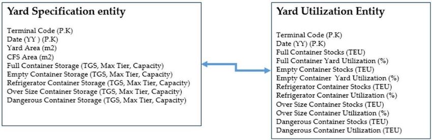
· Process
Process 1: 1: In
In Yard
Yard Specification
Specification entity,
entity, the
the Full
Full Container Storage’s Capacity
Container Storage’s Capacityare areselected
selectedby by
primary key of Terminal Code and Date. Go to Yard Utilization
primary key of Terminal Code and Date. Go to Yard Utilization Entity. Entity.
· Process
Process2:2:UseUsethe
theprimary
primary key used
key in Process
used 1 in 1the
in Process in Yard Utilization
the Yard entityentity
Utilization to select
to the current
select the
stocks of the full container.
current stocks of the full container.
· Process 3:
Process 3: As
As Yard
Yard Utilization
Utilization is defined as containers
containers on on hand
hand divided
dividedbybytotal
totalavailable
availableslots,
slots,
usethe
use theresult
resultofofprocess
process1 1asasthe
the denominator
denominator and
and thethe result
result of Process
of Process 2 as2 the
as the numerator
numerator to
to find
find the yard utilization
the yard utilization rate. rate.
· Process4:
Process 4: Apply
Apply Process
Process 22 and
and 33 to
to other
other container
containertypes,
types,such
suchasasempty,
empty,refrigerator,
refrigerator,over
oversize,
size,
and dangerous container, and calculate the yard utilization
and dangerous container, and calculate the yard utilization rate. rate.
Figure 9.
Figure 9. ERA
ERA diagram
diagram for
for yard-related
yard-related PPI.
PPI.
Theoutput
The outputabout
about thethe number
number of calling
of calling shipsships
andand yardyard utilization
utilization is shown
is shown in Figure
in Figure 8. This8.shows
This
shows a trend of 36 months of which the X-axis is monthly and Y axis
a trend of 36 months of which the X-axis is monthly and Y axis on the left shows yard utilization of on the left shows yard
utilization
full and empty of full and empty
container. container.
Referring Referring
to Figure to Figure 8,perspective,
8, in descriptive in descriptive the perspective,
yard utilization the of
yard
full
utilization
and of full and
empty containers forempty containers
the recent month of for the recent
a terminal month
is 56% andof 81%, a terminal
respectively. is 56%Using andthe81%,
time
respectively.
series method,Using
the yardthe time series method,
utilization of full andtheempty
yard utilization
containersofafterfull and empty is
12 months containers
predictedafter 12
at 62%
months
and 87%,isrespectively.
predicted at 62% and 87%, respectively.
As a result ofofthe
As a result theforecast,
forecast,this
thisproblem
problem can can be
be solved
solved byby either
either increasing
increasing the the empty
emptycontainer
container
storage or removing it with ODCY. However, the first method is limited due to the narrowyard
storage or removing it with ODCY. However, the first method is limited due to the narrow yardarea,
area,
andgenerally
and generallythethesecond
secondmethod
method isis widely
widely used.
used. Another
Another alternative
alternative could
could consider
consideraamethod methodof of
lowering the peak for each day of the week, but it was found that there
lowering the peak for each day of the week, but it was found that there is a little peak of the yardis a little peak of the yard
utilizationrate
utilization ratefor
foreach
eachdaydayofofthe
the week.
week. In
In particular,
particular, the the relationship
relationship between
betweenthroughput
throughputand andyard
yard
utilizationwas
utilization wasfound
foundto tobe
beaanegative
negative relationship
relationship (refer
(refer Figure
Figure 10).
10). It
It turned
turned out outthat
thatthe
theadjustment
adjustment
ofofthe
thequantity
quantityof ofthe
theday
dayof ofthe
theweek
weekdid did not
not help
help improve
improve the the yard
yard utilization.
utilization.You can also read