INSTALLATION GUIDE - Home Networking Solutions - Clipsal
←
→
Page content transcription
If your browser does not render page correctly, please read the page content below
INSTALLATION GUIDE

              Home
            Networking
             Solutions
CLIPSAL STARSERVE® INSTALLATION GUIDE - CONTENTS

Section 1 - What is Clipsal StarServe®?                                                                                       Section 6 - Phone/Data Minimum Cabling Requirements
What is Clipsal StarServe ®?.................................................................................. 4              Telephone/Data Cabling ...................................................................................... 53
Video Distribution.................................................................................................. 4        Patch Panels ........................................................................................................ 53
Telephone and Data Distribution ........................................................................... 5                 Ethernet Switches................................................................................................ 53
                                                                                                                              Patch Leads ......................................................................................................... 53
Section 2 - Introduction to MATV Basics                                                                                       Required Data Tools ............................................................................................ 53
MATV Introduction ................................................................................................ 6          Recommended Cabling ....................................................................................... 54
Signal Strength ...................................................................................................... 7
Signal Quality......................................................................................................... 8     Section 7 - Telephone/Internet - How To Connect
Signal Losses - Cable ............................................................................................ 9          Telephone Connection ......................................................................................... 55
Signal Losses - Splitters ..................................................................................... 10            Jumpering Telephone Outlets ............................................................................. 56
Clipsal Antennas - High Performance Models ....................................................11                             Mode 3 Security System Connection ................................................................. 57
                                                                                                                              ADSL Connection................................................................................................. 58
Section 3 - Clipsal StarServe® Product Introduction                                                                           ADSL Connection with Jumpering Leads ........................................................... 59
3105ABEN Slimline Enclosure............................................................................. 12                   ADSL Switch Modem Router Connection ........................................................... 60
8000LEN Lite Sized Enclosure ............................................................................ 13
8000MEN Mid Sized Enclosure ........................................................................... 14                    Section 8 - Data Cabling - How To Connect
3105PENF / 3105PENS Professional Enclosures ............................................... 15                                Patch Panel Setup - Data Cabling ....................................................................... 61
Video Distribution Units ................................................................................. 16-17              Patch Panel Connection for Structured Cabling System ................................... 62
3105VDU38IRT Distribution Unit........................................................................ 18                     Telephone Distribution Using a Telephone Patch Panel ..................................... 63
3105VDU24T Distribution Unit ........................................................................... 19
8073/8VHPIR Video Hub ..................................................................................... 20                Section 9 - Subscription TV Cabling Requirements/Overview
8072/6VHP Video Hub ........................................................................................ 21               FOXTEL IQ Cabling Requirements - Single Outlet Domestic ............................. 64
Clipsal StarServe ® VDU Power Options ............................................................. 22                        AUSTAR Cabling Requirements - Single Outlet Domestic ................................. 65
Clipsal Digital Ready Antennas ........................................................................... 25                 Multiple Subscription TV Decoder Cabling Requirements - Domestic ............. 66
Modulators........................................................................................................... 26      Apartment Cabling Requirements - Commercial Installations .......................... 67
Emitter Leads & Infrared Targets........................................................................ 27
Patch Panels - Data and Telephone..................................................................... 28                     Section 10 - Cabling Considerations
Switches - Data Patch Panels ............................................................................. 29                 Key Area 1 - The Lounge Room........................................................................... 68
8001/4EX Output Expander................................................................................. 30                  Key Area 2 - The Master Bedroom ...................................................................... 69
8000INJ IR Injector ............................................................................................. 30          Key Area 3 - Other Bedrooms.............................................................................. 69
8000DCB DC Block .......................................................................................... 31                Key Area 4 - Study/Other Bedrooms................................................................... 69
8000AVB RCA to Cat-5 Cable Adaptor ................................................................ 31                        Key Area 5 - The Kitchen ..................................................................................... 70
                                                                                                                              Smart Wired Wall Plate ....................................................................................... 70
Section 4 - Minimum TV Cabling Requirements                                                                                   Other Areas .......................................................................................................... 70
TV Cabling Requirements.................................................................................... 32
F-Type Connectors ............................................................................................... 32          Section 11 - Troubleshooting Guides
MATV Tools Required .......................................................................................... 32             Infrared Troubleshooting Guide ..................................................................... 71-72
TV Mechs ............................................................................................................. 33     TV Reception Troubleshooting Guide - Free to Air Picture ........................... 73-74
TV Fly Leads......................................................................................................... 33      TV Reception Troubleshooting Guide - Modulated Channels .............................74
Digital Terrestrial Meter ...................................................................................... 33
Conventional TV Cabling ..................................................................................... 34              Section 12 - Clipsal StarServe® FAQs
                          ®
Clipsal StarServe TV Cabling ............................................................................ 35                  Clipsal Starserve Frequently Asked Questions .............................................75-76
3105VDU38IRT TV Wiring Diagram ................................................................... 36
3105VDU24T TV Wiring Diagram ....................................................................... 37                       Notes Pages
8073/8VHPIR TV Wiring Diagram ...................................................................... 38                       Notes ............................................................................................................... 77-79
8072/6VHP TV Wiring Diagram .......................................................................... 39

Section 5 - Video Distribution - How To Connect
Antenna Input ...................................................................................................... 40
Antenna Input - Using an Amplifi er with the VDU .............................................. 41
Antenna Outputs .................................................................................................. 42
Modulator Input B - Distribution of Devices ....................................................... 43
Setup of the Modulator........................................................................................ 44
Modulator AV Connections.................................................................................. 45
Modulator AV Connections - Y-Lead Connections ............................................. 46
IR Emitter Leads .................................................................................................. 47
IR Target............................................................................................................... 48
IR Control of Devices........................................................................................... 49
Modulator Input A - Single Surveillance Camera ............................................... 50
Modulator Input A - Multiple Surveillance Cameras .......................................... 51
Surveillance Camera Connection Using an AV Balun ......................................... 52

                                                                                                                                                                                         INSTALLATION GUIDE                                                 3
SECTION 1                                     What is Clipsal StarServe ?                  ®

    What is Clipsal StarServe®?
    Clipsal StarServe ® is three distribution systems in one for the home:

                                               AND/OR                              AND/OR

             Digital and Analogue                       Telephone/Internet                         Data Networking
              Video Distribution                            Distribution
    You can take advantage of just one or utilise all three areas - the choice is yours.

    Video Distribution
    Apart from distributing analogue or digital free to air TV, Clipsal StarServe ® also enables the user to distribute other
    devices such as DVD players, video recorders, subscription TV decoders and surveillance cameras to be viewed on
    any TV connected to the Clipsal StarServe ®.

    Now every TV in your home can access free to air channels, subscription TV decoders, DVD players, video recorders,
    surveillance cameras, etc.

    Clipsal StarServe ® unlocks your home entertainment centre. Now everyone can watch what they want, when they
    want to watch it.

    Some models will allow the IR control of these other devices from rooms other than the main entertainment area.

                        Only TWO extra coax cables are required in addition to the standard TV cabling.

4           INSTALLATION GUIDE
SECTION 1                                     What is Clipsal StarServe ?                 ®

Telephone and Data Distribution
In today’s homes the need to have telephone access and internet access is essential.

Clipsal StarServe ® facilitates the distribution of telephone and internet cabling in a simple and easy to understand
manner. Clipsal StarServe ® can also facilitate a high-speed data network so that you can network computers, printers
and AV equipment together.

Hard wired cabling is the best possible solution for any installation but failure to prepare for cabling may be very
costly in the future. The cost of trying to install cabling after a new home has been built is approximately three to four
times the initial cost. If you have a two storey home then it may be impossible to get cables down walls unless you
make holes and damage walls or ceilings.

Even if you are going to have a wireless network within your home, Clipsal StarServe ® can accommodate this
requirement and connect your wireless network to the Internet.

                                                                                             3105PENF
                                                                                        Clipsal StarServe®
                                                                                             Enclosure

                                                                                            INSTALLATION GUIDE               5
SECTION 2                                       Introduction to MATV Basics

    MATV Introduction

    What does MATV stand for?
    Master Antenna TeleVision:

    The master antenna is used for supplying one TV outlet, or multiple TV outlets with TV signals. The most basic MATV
    system is an antenna connected to a TV outlet, along with a fly lead to connect the system to the TV.

    The antenna is designed to receive TV signals. The cable is designed to carry the TV signals to the outlet. The outlet
    is the interface for a fly lead to connect to the TV. The fly lead connects the wall plate to the TV.

                                                                                              Fly Lead

                                                                 Wall Outlet

    Where multiple outlets are required a splitter or series of splitters are used to distribute the signal to as many
    outlets as required.

                  Antenna
                                                                                   Wall Outlets           Fly Leads

                                                   Splitter

                                    The antenna is designed to receive the TV signal.
                 The cabling system is designed to carry the TV signal to the TV without any interference.

                                                 IMPORTANT NOTE:
                      All Clipsal MATV products including Clipsal StarServe® are capable of
                             distributing DIGITAL AND ANALOGUE free to air TV signals.
                                      Analogue TV             VHF 0 - 12 & UHF 28 - 69
                                      Digital TV              VHF 6 - 12 & UHF 28 - 69

6           INSTALLATION GUIDE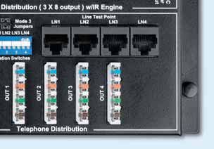
SECTION 2                                       Introduction to MATV Basics

Signal Strength
The principals of signal strength for MATV systems are not unlike that of the electrical principals for voltage at power points.

The units of measurement are as follows:

• electrical unit of measurement is the Volt (V)

• MATV unit of measurement is the decibel Micro Volt (dBuV), commonly referred to as “dB”.

The ideal voltage for a power outlet is 240 Volts, with a tolerance of 5%. This means that you can have as low as 228
Volts or as high as 252 Volts to comply with the Australian Standards.

The voltage is measured using a multimeter. You set the multimeter to the voltage setting and test for voltage. The
ideal signal level for a combined analogue / digital MATV system is similar.

The ideal MATV signal strength at the outlet is 69dBuV with a tolerance of 5%. For excellent quality pictures, you
require signal strength between 65-72dBuV. The MATV signal strength is measured using a field strength meter. You
set the field strength meter to the channel you wish to test and it will show you a reading of the signal at the outlet.

                                                    Ideal Signal Levels
                    MATV Outlet - 69dBuV                                              Standard Outlet - 240V

                Test with field strength meter                                          Test with multi meter

    LOW                                     ACCEPTABLE HIGH
   SIGNAL                                     SIGNAL   SIGNAL             TOO LOW                                 TOO HIGH

       62dBuV   65dBuV                  72dBuV     75dBuV                           228V                   252V
                           69dBuV

                                           A field strength meter is ESSENTIAL.

                                                                                                  INSTALLATION GUIDE               7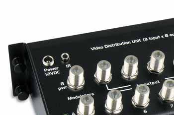
SECTION 2                                        Introduction to MATV Basics

    Signal Quality
    There are two parts to a perfect TV picture, signal strength and signal quality. You can have excellent signal strength
    but if your signal quality is poor then this will result in poor quality pictures.

    Many of the problems faced with signal quality have been overcome with the introduction of digital TV. For example
    with digital TV you will not get “ghosting”. Clear line of sight is obviously the best possible scenario for high quality
    TV reception but often cannot be achieved.

    We need to avoid the following when installing antennas:

    • DO NOT install antennas in the ceiling space

    • DO NOT install antennas with trees in the way of line of sight

    • DO NOT install antennas within one metre of the roof.

    Before you install an antenna:
    • DO a site survey; this is a walk on the roof with
       an antenna and digital field strength metre. This
       will give you an indication of the best possible
       location to install the antenna on the roof

    • DO check each TV station on the site survey. This
       confirms that it is the best possible location for all
       TV stations reception.

    Bit error rate
    BER – Bit error rate measures the number of
                                                                                                           No picture
    errors on the incoming signal. Too many errors
    will result in pixilation, boxing or freezing of the
    picture. There is a four star rating associated with
    digital signal reception:

                                                                                                        Pixelated picture

                   FAIL                              FAIL                            PASS                          PASS
       VERY POOR QUALITY                    POOR QUALITY                  GOOD QUALITY              EXCELLENT QUALITY

                                It is the installer’s responsibility to follow the appropriate
                                  Occupational Health and Safety (OH&S) work practices.

8           INSTALLATION GUIDE
SECTION 2                                   Introduction to MATV Basics

Signal Losses - Cable
Losses are a part of any MATV system. You may start out with an acceptable signal level at the antenna but due to
losses in the cable or splitter, the signal may not be acceptable when at the outlet.

Losses are calculated separately for VHF and UHF frequencies. The golden rule; is the higher the frequency the higher
the loss.

      VHF = Very High Frequency                         45 - 470 MHz                           Channels 0 - 12

      UHF = Ultra High Frequency                       471 - 860 MHz                           Channels 21 - 69

We need to calculate losses for both VHF and UHF in every TV design to ensure that we have a balanced system.
Clipsal RG6 cable losses are linear. This means that you can multiply the losses for one metre by the length of the
cable run to get the losses over that distance.

       2B6QXX Cable Losses           Frequency         1.0m           5.0m          10.0m         20.0m           30.0m

                                     VHF (0-12)      0.053dB        0.265dB        0.53dB         1.06dB          1.59dB

                                    UHF (21-69)       0.21dB         1.05dB         2.1dB          4.2dB          6.3dB

A balanced system is a MATV system that has an acceptable signal level (65-72dBuV) at every outlet within the
system, regardless of the length of cable to the outlet.

In domestic settings this is not usually an issue if the distribution of the signal is from a central location. This is more
of an issue when distributing TV signals to multi storey apartments and hotels with long cable runs.

In a domestic situation the shortest cable run can be one metre and the longest cable run can be 45 metres without
having to use some form of equalisation to balance the system.

               45 Metres                                         1 Metre

                                                                                              INSTALLATION GUIDE               9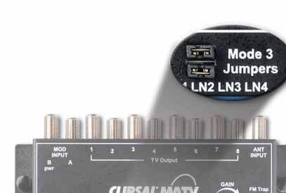
SECTION 2                                     Introduction to MATV Basics

     Signal Losses - Splitters
     Losses over splitters are just as important to calculate as the losses over cable. The value of the loss will be different
     for VHF and UHF (the golden rule is the higher the number of splits, the higher the losses).

     The Clipsal StarServe ® VDU is a NO-LOSS SPLITTER.

     The losses over each output port of the splitter are the same.

     If you changed a two way splitter for a four way splitter you may have poor picture quality due to the fact that you
     have added losses into the system and reduced the signal strength to each outlet by 4dB on VHF and 3.4dB on UHF.
     An eight way splitter would also require an amplifier.

                                 Antenna input

                    SIGNAL IN                                                                               SIGNAL IN
                       70dBuV                                                                                   70dBuV
                                                                                   SIGNAL OUT
                                                                                      72dBuV

                                              SIGNAL
                                                OUT
                                               VHF: 57.8dB
                                               UHF: 57.2dB

                                                                                            SIGNAL
                                                                                            NO LOSS
                                                                                           Option of 5dB GAIN
                                                                                          or 15dB ATTENUATION

                            Frequency            2 Way       3 Way       4 Way         6 Way         8 Way

                         46-470MHz VHF         < 3.5dB       < 6.1dB     < 7.5dB     < 10.2dB       < 11.2dB

                        471-860MHz UHF         < 4.4dB       < 6.3dB     < 7.8dB     < 10.7dB       < 11.8dB

10           INSTALLATION GUIDE
SECTION 2 Introduction to MATV Basics
Clipsal Antennas - High Performance Models
2ANCOM3 13 Element VHF 1-12 UHF 28-50
For use in PRIME signal reception areas.
This antenna will suit areas such as Adelaide, Melbourne,
Sydney, Brisbane, Perth, Hobart and Launceston.
2ANCOM4 17 Element VHF 2-12 UHF 28-40
For use in FRINGE signal reception areas.
This antenna will suit areas such as Adelaide, Melbourne,
Sydney, Brisbane, Perth, Hobart and Launceston.
2ANCOM6 28 Element VHF 2-12 UHF 28-40
For use in OUTER FRINGE signal reception areas.
This antenna will suit areas such as Adelaide, Melbourne,
Sydney, Brisbane, Perth, Hobart and Launceston.
2ANCOMD14 14 Element VHF 6-12 UHF 28-50
For use in PRIME/FRINGE signal reception areas.
This antenna will suit both digital and analogue signals
from VHF 6-12 and UHF 28-50.
2ANCOMD14WB 14 Element - Wide Band VHF 6-12 UHF 28-69
For use in PRIME/FRINGE signal reception areas.
This antenna will suit both digital and analogue signals
from VHF 6-12 and UHF 28-69.
2ANCOMD24 24 Element VHF 6-12 UHF 28-50
For use in FRINGE signal reception areas.
This antenna will suit both digital and analogue signals
from VHF 6-12 and UHF 28-50.
INSTALLATION GUIDE 11SECTION 3 Clipsal StarServe Product Introduction
®
3105ABEN Slimline Enclosure
The size of the enclosure is determined by the number of cables and active equipment required inside the
enclosure. Choose an appropriate enclosure to accommodate the cabling required for the installation.
Features
• Designed to be recessed into 63mm stud walls.
• Installed at second fix stage.
• 1-11 RG6 quad shield coax cables for TV distribution.
• 1-8 Category 5e or Category 6 data cables for structured cabling network.
• 1-4 Incoming telephone lines.
• 1 x 4 port ADSL switch / modem router (Netgear product number DG834).
• Cut-out template provided.
Specifications
Dimensions: 383mm high x 269mm wide x 88mm deep (74mm deep in wall)
Cut out size: 356mm high x 213mm wide x 74mm deep
12 INSTALLATION GUIDESECTION 3 Clipsal StarServe Product Introduction
®
8000LEN Lite Sized Enclosure
8000LEN Enclosure 8000LENFK Enclosure Flushing Kit
The size of the enclosure is determined by the number of cables and active equipment required inside the
enclosure. Choose an appropriate enclosure to accommodate the cabling required for the installation.
Features
• Small enclosure to suit TV and / or telephone distribution.
• 1-11 RG6 quad shield coax cables for TV distribution.
• 1-8 Category 5e or Category 6 data cables for telephone distribution.
• 1-4 Incoming telephone lines.
Specifications
Dimensions: 330mm high x 210mm wide x 130mm deep
8000LENFK - Flushing kit available
INSTALLATION GUIDE 13SECTION 3 Clipsal StarServe Product Introduction
®
8000MEN Mid Sized Enclosure
8000MEN Enclosure 8000MENFK Enclosure Flushing Kit
The size of the enclosure is determined by the number of cables and active equipment required inside the
enclosure. Choose an appropriate enclosure to accommodate the cabling required for the installation.
Features
• Two vertical rails for increased wiring room and more cables.
• Surface mount.
• Flushing kit available for recess mount.
• 1-11 RG6 quad shield coax cables for TV distribution.
• 1-16 Category 5e or Category 6 data cables for structured cabling network.
• 1-4 Incoming telephone lines.
• 1 x 3105ADJB Audio distribution junction box for more than four zones of audio distribution.
Specifications
Enclosure: 450mm high x 415mm wide x 145mm deep
8000MENFK - Flushing Kit available
14 INSTALLATION GUIDESECTION 3 Clipsal StarServe Product Introduction
®
3105PENF Professional Flush Mount Enclosure
3105PENS Professional Surface Mount Enclosure
3105PENF Enclosure 3105PENS Enclosure
The size of the enclosure is determined by the number of cables and active equipment required inside the
enclosure. Choose an appropriate enclosure to accommodate the cabling required for the installation.
Features
• Choice of first fix or second fix mounting.
• Suits different thickness’ of plaster board: 10mm, 13mm and 16mm.
• Dual power outlet inside enclosure.
• Family look – power, C-Bus and Clipsal StarServe ® in the same style of enclosure.
• 1-21 RG6 quad shield coax cables for TV distribution.
• 1-48 Category 5e or Category 6 data cables for structured cabling network.
• 1-8 Incoming telephone lines.
• 1 x 3105ADJB Audio distribution junction box for more than four zones of audio distribution.
• Uses keystone data jacks available in CAT5e and Cat6 (RJ88SMAS, RJ88SMA6).
Specifications
3105PENF
Enclosure: 880mm high x 466mm wide x 119mm deep
Cut out size: 882mm high x 468mm wide x 69mm deep
Recessed frame: 954mm high x 525mm wide
3105PENS
Dimensions: 880mm high x 466mm wide x 114mm deep
INSTALLATION GUIDE 15SECTION 3 Clipsal StarServe Product Introduction
®
Video Distribution Units
3105VDU38IRT 3105VDU24T 8072/6VHP 8073/8VHPIR
MATV AND TELEPHONES MATV ONLY
Distribution
The VDU distributes digital and analogue free to air TV signals from the antenna input to all TV outputs on the VDU. This
works as a splitter but one of the special features is that the Clipsal VDU is a powered splitter which has no losses from
the input to the outputs.
NOTE: The Clipsal StarServe ® VDU is classed as one TV point when choosing an antenna.
Variable Gain Control
The Clipsal StarServe ® VDU has a variable gain control to make it easy to adjust for the ideal
signal strength and best possible picture. The variable gain control can amplify the incoming
signal by 5dBuV or decrease the signal strength by 15dBuV. This feature of the Clipsal
StarServe ® VDU makes installation easy.
Selectable FM Trap
The selectable FM trap is a feature that is built into the Clipsal StarServe ® VDU. FM frequencies
can cause interference with other TV frequencies and need to be removed from the distribution
system. This can be done with the push of a button on the Clipsal StarServe ® VDU.
Combination VDU
A combination VDU has been designed to suit the recessed slimline enclosures required in
today’s markets. These VDUs combine the features of the TV cabling and the connection of
the telephone, security system and ADSL services to create a neat, compact solution. These
are entry level solutions and are ‘set and forget’ style products, when using these products there
is no requirement for patching to achieve a basic setup.
The telephone card can accept one to four incoming telephone lines and distribute up to four locations for each line.
The telephone lines can be expanded by jumpering from one to another.
In other words, one incoming line can be expanded to 16 outlets and two incoming lines can be expanded to up to
eight outputs per line.
There is a Mode 3 socket for the connection of a security system to VDU models 3105VDU38IRT and 3105VDU24T.
16 INSTALLATION GUIDESECTION 3 Clipsal StarServe Product Introduction
®
Modulated Inputs
The modulated inputs on the Clipsal StarServe ® VDU are designed for the connection of a modulator to the VDU. This
enables the distribution of other devices such as a DVD player, VCR, subscription TV decoder or surveillance camera
to all TV outputs on the VDU.
There are two types of VDU modulated inputs:
3105VDU24T & 8072/6VHP
The modulated inputs on the 3105VDU24T and 8072/6VHP are designed for the connection
of a modulator to distribute devices such as subscription TV decoders, DVD players, VCRs,
etc from one central location to all outputs on the VDU.
The VDU can be powered remotely from this modulated input over the coax cable.
The 3105VDU24T and 8072/6VHP have no IR (Infrared) control of these devices.
3105VDU38IRT & 8073/8VHPIR
There are two modulated inputs on these models that allow for the distribution of devices to
all TV outputs.
Modulator Input A is designed for the connection of a modulator to distribute devices that do not
require IR control such as surveillance cameras. This modulator input cannot be used to power the VDU.
Modulator Input B is designed for the distribution of devices such as subscription TV decoders, DVD players, VCRs,
etc from one central location to all outputs on the VDU with the potential of IR remote control of these devices from
other rooms. This modulated input can be used to remotely power the VDU.
These models have an IR engine built into the VDU to enable the IR control of devices from remote locations with the
addition of an IR compatible modulator, IR emitter leads and IR targets.
Power Output
The power output has been designed to power an external device such as a switch/modem
router that uses the same 12V d.c. power plug at the VDU.
This feature was built to accommodate a fully working system that does not require 240V
power inside the enclosure which houses the active equipment.
INSTALLATION GUIDE 17SECTION 3 Clipsal StarServe Product Introduction
®
3105VDU38IRT Infrared Video and Telephone Distribution Unit
Modulator input ‘A’ for the distribution of
devices such as surveillance cameras via
a modulator to all TV outputs of the VDU Distributes digital ready TV to
(Modulator sold separately) eight locations of your choice Antenna input
INPUT A has no Infrared control
Modulator input ‘B’ for the Has a selectable FM trap
distribution of subscription TV, for filtering out
DVD and video via a modulator unwanted signals
(Modulator sold separately)
12Vd.c. power output
12Vd.c. power
for switch modem
input
routers
Variable gain control
for adjusting output
IR expansion port: signal strength to
Allows infrared optimum levels
connectivity from
one VDU to another
Enables the user to remotely control
Has a security connection for your Distributes four telephone, dial- up
subscription TV, DVDs etc from another
security system alarm dialler internet or fax lines up to four locations
room in conjunction with the
for each line
Clipsal IR products
Telephone distribution only, NOT DATA
Suitable for ALL Clipsal StarServe® Enclosures
18 INSTALLATION GUIDESECTION 3 Clipsal StarServe Product Introduction
®
3105VDU24T Video and Telephone Distribution Unit
Modulator input for the distribution of
other services such as subscription TV, Distributes digital ready TV to
DVD, video, surveillance cameras etc. via four locations of your choice Antenna input
a modulator to all TV outputs of the VDU
(Modulator sold separately)
Has a selectable FM trap
for filtering out
unwanted signals
12Vd.c. power output
12Vd.c. power
for switch modem
input
routers
Variable gain control
for adjusting output
signal strength to
optimum levels
Distributes four telephone, dial- up
internet or fax lines up to four locations
Has a security connection for your
for each line
security system alarm dialler
Telephone distribution only, NOT DATA
Suitable for ALL Clipsal StarServe® Enclosures
PLEASE NOTE: this model DOES NOT support the remote control of devices in other rooms
INSTALLATION GUIDE 19SECTION 3 Clipsal StarServe Product Introduction
®
8073/8VHPIR Video Hub
Antenna input
Modulator input ‘B’ for the distribution of
subscription TV, DVD, video via a modulator
(Modulator sold separately)
Has a selectable FM trap
for filtering out
unwanted signals
12V d.c. power input
Variable gain control
for adjusting output
signal strength to
optimum levels
Modulator input ‘A’ for the distribution of
devices such as surveillance cameras via
a modulator to all TV outputs of the VDU
(Modulator sold separately)
Distributes digital ready TV to
INPUT A has no infrared control eight locations of your choice
Suitable for 3105PENF, 3105PENS, 8000MEN and 8000LEN Enclosures
20 INSTALLATION GUIDESECTION 3 Clipsal StarServe Product Introduction
®
8072/6VHP Video Hub
Modulator input for the distribution of
other services such as subscription TV,
DVD, video, surveillance cameras etc. via Antenna input
a modulator to all TV outputs of the VDU
(Modulator sold separately)
Variable gain control
for adjusting output
signal strength to
12 Vd.c. power input
optimum levels
Distributes digital ready TV to
six locations of your choice
Suitable for 3105PENF, 3105PENS, 8000MEN and 8000LEN Enclosures
INSTALLATION GUIDE 21SECTION 3 Clipsal StarServe Product Introduction
®
Clipsal StarServe® VDU Power Options
Remote Powering of the VDU - Modulator
The modulator can be used to power the VDU instead of the power injector. You connect the modulator to the “MOD
INPUT B” of the VDU.
You must make sure that the VDU is disconnected from any other means of power before you remotely power the VDU.
Simply slide the remote power switch from OFF to ON. This will power the VDU from the modulator.
Wallplate located B 1 2
in your MAIN
ENTERTAINMENT AREA
RG6 Quadshield
Cables
DO NOT connect a power supply to the VDU
when it is being powered via the modulator.
The IR system will only work when the remote
power switch is in the ON position.
22 INSTALLATION GUIDESECTION 3 Clipsal StarServe Product Introduction
®
Power Injector
The power injector is used to remotely power the VDU when a modulator is not installed into the system. The power injector
is connected to the modulator return path “MOD INPUT B” connection on the wall plate in the main entertainment area.
Connect the power injector to “MOD INPUT B” on the 3105VDU38IRT and 8073/8VHPIR and to “MOD” on the
3105VDU24T and 8072/6VHP.
The 12V d.c. plug pack is plugged into the power injector. The plug pack is then plugged into a power point and turned
on. The green power LED on the VDU will illuminate when the power is turned ON.
B 1 2 3-8
RG6 Quadshield
Cables
3105PI12VDC
Power Injector
DO NOT connect the power injector to any TV output on the VDU.
DO NOT connect the modulator to the ‘MOD INPUT A’.
INSTALLATION GUIDE 23SECTION 3 Clipsal StarServe Product Introduction
®
Local Powering of the VDU - Plug Pack
The plug pack can be directly plugged into the VDU power input when power is available inside the Clipsal
StarServe ® enclosure.
The green power LED on the VDU will illuminate when the power is turned ON.
When connecting a modulator, DO NOT SWITCH THE
REMOTE POWER SWITCH TO ON, as this may damage the VDU.
DO NOT CONNECT THE MODULATOR TO THE ‘MOD INPUT A’.
24 INSTALLATION GUIDESECTION 3 Clipsal StarServe Product Introduction
®
Clipsal Digital Ready TV
TV Cabling
Solutions
Catalogue
When it comes to antenna installation, the choice is clear
Catalogue
number: 11954
To obtain a brochure or for
further information call 1800 728 728
INSTALLATION GUIDE 25SECTION 3 Clipsal StarServe Product Introduction
®
Modulators
Modulators connect active devices such as your subscription TV decoder and DVD player so that they can be distributed
to all other TV outlets connected to Clipsal StarServe ®. The modulator converts composite video signals into analogue
UHF frequencies. Your TV or tuner must be able to receive analogue frequencies for modulated channels.
Single Channel Modulator - 8071VMP (MONO) and 8071VMS (STEREO)
Single channel modulators will distribute one device to any TV connected to Clipsal StarServe ®. A single channel
modulator is generally used for the distribution of surveillance cameras at the front door.
2 Channel Modulator - 8072VMPIR (MONO) and 3105M2SIR (STEREO)
Two channel modulators will distribute two devices such as subscription TV and a DVD player. This model is IR enabled to
allow for the remote controlling of devices in other rooms over the coax cable. Up to four devices can be controlled using
dual emitter leads.
4 Channel Modulator - 8074VMPIR (MONO) and 3105M4SIR (STEREO)
Four channel modulators will distribute four devices such as subscription TV, DVD, video and a digital set top box to
all outlets connected to Clipsal StarServe ®.
This model is IR enabled to allow for the remote controlling of devices in other rooms over the coax cable. Up to four
devices can be controlled using dual emitter leads.
Modulator located
in your MAIN
ENTERTAINMENT AREA
26 INSTALLATION GUIDESECTION 3 Clipsal StarServe Product Introduction
®
Emitter Leads
Infrared emitter leads are placed on the IR receiver of the device you wish to control. There is a sticky backing
provided on the reverse side of the lead which attaches easily to the device.
8050LD 8050/2LD
Single Emitter Lead Double Emitter Lead
Connect the leads to the modulator located in the
MAIN ENTERTAINMENT AREA (the lounge room)
Infrared Targets
An infrared target is required for EACH ROOM you wish to remotely control devices from. Simply place it in a
convenient location either alongside or underneath the TV.
8050TR
Infrared Transmitter
8050TT 8050FT
Tube Target Flat Target
8000INJ
8050ST IR Injector
Shelf Target (Refer PAGE 30)
The IR target can be connected to any TV outlet in any room.
The 8050TT, 8050ST and 8050FT are connected using the 8000INJ IR injector.
INSTALLATION GUIDE 27SECTION 3 Clipsal StarServe Product Introduction
®
Patch Panels - Data and Telephone
Data
Data patch panels are used for the termination of data cables inside the Clipsal StarServe ® enclosure.
A data outlet is a Category 5e or 6 cable with a connector terminated onto each end. In essence, it is a high
performance extension cord for the connection of two or more computers. A patch lead at either end connects the
devices you want to network.
Telephone
If you require the ability to move telephone lines to different outlets within your home, you can use a telephone patch
panel. A data patch panel is required to connect to all field outlets. You can achieve this in two ways:
OPTION 1: Use the Clipsal 8052/4RJSMB Telephone Patch Panel with internal connections for four extensions for
each line (maximum two lines per patch panel).
OPTION 2: Use an eight port patch panel and connect as many lines as you need.
LINE 1 LINE 2
1 1 1 1 2 2 2 2
TELEPHONE
PATCH PANEL
Four Telephone Four Telephone
extensions extensions
to LINE 1 to LINE 2
1 2 3 4 5 6 7 8
DATA PATCH PANEL BLUE
PAIR 1
PAIR
Telephone
Connection
28 INSTALLATION GUIDESECTION 3 Clipsal StarServe Product Introduction
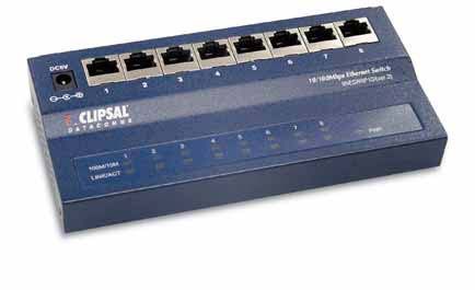
®
Switches - Data Patch Panels
A switch connects two or more computers together so that they can communicate with each other.
95ESW5P10/ 95ESW8P10/
5-Port Ethernet Switch 8-Port Ethernet Switch
1
PC
3
6
PC
DATA 1 2 3 4 5 6 7 8
PATCH
PANEL
Network printer
(Ethernet connection)
Any computer can network with other computers
connected to the switch.
Network printers can be connected so everyone on
the network can use one printer.
INSTALLATION GUIDE 29SECTION 3 Clipsal StarServe Product Introduction
®
8001/4EX Output Expander
The output expander allows you to increase the number of Clipsal StarServe ®
outputs without the use of an additional video hub. It consists of one input
and four outputs.
Connect an output of your existing video hub to the input of the expander.
You will lose the use of an output on the video hub but gain an additional four
outputs on the output expander.
You can connect an output expander to each output on a video hub, providing
up to 32 outputs from an eight input hub.
8000INJ IR Injector
The IR injector allows you to insert an IR target anywhere along the RG6
cable feed between the Clipsal StarServe ® video hub and the TV. This means
a target can be placed away from the TV screen to eliminate interference
from the TV or plasma screen.
The IR injector can be used with a tube (8050TT), flat (8050FT) or shelf
(8050ST) target.
8050TT 8050FT 8050ST
Tube Target Flat Target Shelf Target
8000INJ
F-Type to IR Injector F-Type fly
PAL fly lead lead
Wallplate
Plasma TV
8050FT
Flat Target
30 INSTALLATION GUIDESECTION 3 Clipsal StarServe Product Introduction
®
8000DCB Coaxial DC Block
The DC block is used to filter out DC Voltage and infrared (IR) control pulses
on a Clipsal StarServe ® RG6 cable feed. It is inserted in an individual cable
feed. It contains a capacitor which allows high frequency video and audio to
pass, but blocks DC and low frequency IR.
The 8000DCB is recommended when an amplifier is connected to the input
“ANT INPUT” on any StarServe VDU.
Refer to page 41 for
wiring connection
details.
8000AVB RCA to Cat-5 Cable Adaptor
This adaptor allows you to transmit standard video and audio signals, as
well as DC power over Category 5 or Category 5e cable. An RCA to Category
5 cable adaptor is used at each cable end, making it suitable for security
camera installations integrated with Clipsal StarServe ®.
The 8000AVB has two baluns and one power lead supplied in each pack (one
for either end of the cabling network).
Refer to page 52 for
wiring connection
details.
INSTALLATION GUIDE 31SECTION 4 Minimum TV Cabling Requirements
TV Cabling Requirements
All TV cabling is run using RG6 Quad Shield Coax Cable. The RG6 Quad Shield Coax has excellent shielding against
electrical noise, which can affect picture quality.
The Clipsal Quad Shield Coax Cable is FOXTEL approved. The use of a top quality coax cable will greatly minimise
any call-backs for the electrical contractor.
3105RG6Q3B
RG6 Quad Shield Coax Cable
F-Type Connectors
F-Type connectors are the best connectors to use in an MATV installation. F-Type connectors have very low losses
and are easy to connect. Clipsal recommend two types of F-Type connectors on a Clipsal StarServe ® System, the
Radial Crimp 3105RG6F or the Compression Connector 3105RG6FC50.
3105RG6F 3105RG6FC50
Radial Crimp Compression Connector
3105PM-FF
F-Type Female Adaptor
to Male PAL
To make up good quality fly leads on site, Clipsal recommend the use of F-Type to PAL adaptors.
MATV Tools Required
To perform a Clipsal StarServe ® installation quickly and effectively you require the right tools for the job.
3105CS6 3105CT611
Cable Stripper to suit Crimper for Radial Crimp F-Type connection
RG6 Quad Shield
3105CT611C 3105CRFTK
Compression tool to suit F-Type compression connectors MATV Compression Toolbox
32 INSTALLATION GUIDESECTION 4 Minimum TV Cabling Requirements
TV Mechs
The Clipsal 30PFM and 30FFPFMS are straight through connectors. These connectors have excellent electrical
performance and minimal losses. These connectors allow IR to pass through for the remote control IR engine built
into the Clipsal StarServe ® VDU’s 3105VDU38IRT and 8073/8VHPIR.
Failure to use either
of these items may
30PFM 30FFPFMS
result in the infrared F-Type Connectors F-Type to PAL
control to fail. Connectors
TV Fly Leads
Clipsal has F-Type to PAL fly leads in its range to suit Clipsal StarServe ® installations.
Fly leads are the weakest point in any TV system. Fly leads are subjected to being twisted and tangled with power
cords behind TV entertainment units. Using RG6 quad shield coax fly leads will minimise any potential problems
occurring and reduce any potential call-backs.
Fly leads can be manufactured on site by a MATV contractor or purchased as a finished product.
3105FL318MWQ
F-Type to PAL Fly Lead
(White)
3105FL318MBQ
F-Type to PAL Fly Lead
(Black)
Digital Terrestrial Meter
A digital terrestrial meter is used to measure the signal strength of a MATV System. This is one of the most important
tools you can own, as it will save you lots of time and money. Instead of guessing the antenna direction and signal
strength you can accurately align the antenna and measure the signal strength.
2ANDTM
Digital Terrestrial Meter
INSTALLATION GUIDE 33SECTION 4 Minimum TV Cabling Requirements
Conventional TV Cabling
Only one TV can view DVD, subscription TV or video at one time.
34 INSTALLATION GUIDESECTION 4 Minimum TV Cabling Requirements
Clipsal StarServe® TV Cabling
All TVs can view DVD, subscription TV or video at one time.
Only TWO extra coax cables are required.
INSTALLATION GUIDE 35SECTION 4 Minimum TV Cabling Requirements
3105VDU38IRT TV Wiring Diagram
4 3
Location: Location:
MASTER BEDROOM BEDROOM 2
6 5
Location: Location:
BEDROOM 3 BEDROOM 4
VCR and Modulator
must be within one
Location: STUDY Location: OTHER
meter of each other B 1 2
for IR emitter lead. 7 8
Wallplate located
in your MAIN
ENTERTAINMENT AREA
Refer to page 22-24
for VDU powering
options.
Note: 3105VDU38IRT
can support IR control
with the addition of
8050TR, 8050LD and
StarServe modulators
with IR.
36 INSTALLATION GUIDESECTION 4 Minimum TV Cabling Requirements
3105VDU24T TV Wiring Diagram
3
Location:
MASTER
BEDROOM
4
Location:
Wallplate located B 1 2 BEDROOM 2
in your MAIN
ENTERTAINMENT AREA
Refer to page 22-24
for VDU powering
options.
Note: The
3015VDU24T does not
support IR control.
INSTALLATION GUIDE 37SECTION 4 Minimum TV Cabling Requirements
8073/8VHPIR TV Wiring Diagram
Wallplate located
in your MAIN
ENTERTAINMENT AREA
4 3
Location: Location:
MASTER BEDROOM BEDROOM 2
6 5
VCR and Modulator
must be within one Location: Location:
meter of each other BEDROOM 3 BEDROOM 4
for IR emitter lead.
B 1 2
Location: STUDY Location: OTHER
Refer to page 22-24
for VDU powering 7 8
options.
Note: 3105VDU38IRT
can support IR control
with the addition of
8050TR, 8050LD and
StarServe modulators
with IR.
38 INSTALLATION GUIDESECTION 4 Minimum TV Cabling Requirements
8072/6VHP TV Wiring Diagram
3
Location: MASTER
BEDROOM
4
Location: BEDROOM 2
5
Wallplate located B 1 2
in your MAIN Location: STUDY
ENTERTAINMENT AREA
6
Refer to page 22-24
for VDU powering
options.
Location: OTHER
Note: The
3015VDU24T does not
support IR control.
INSTALLATION GUIDE 39SECTION 5 Video Distribution - How to Connect
Antenna Input
The antenna input of the Video Distribution Unit (VDU) has an F-Type connection. The Clipsal StarServe ® VDU has
built in gain control to enable the optimum signal level to be achieved easily with the turn of a screw.
The range of variable gain control is +5dBuV gain (increase) from incoming signal or –15 dBuV attenuation (loss).
The optimum level of signal strength on the output ports of the VDU is 72dBuV.
This means that a minimum signal level of 69dBuV is required at the antenna input (a small margin is allowed
for variation between signals).
The maximum signal level that can be connected to the antenna input is 89dBuV.
The modulator input signal
strength must be within
15dBuV of the output
free to air signal.
69dBuV
minimum
It is ideal to get the signal
levels as close as possible.
Step 1
Measure the incoming signal from the antenna. If the signal is between 69 - 89dBuV, you can connect to the Clipsal
StarServe ® VDU via the antenna input. If the signal strength is below 69dBuV, you will need to EITHER replace the
antenna with a larger model OR use an amplifier to increase the signal strength.
If the signal strength is over 89dBuV, you will have to attenuate the signal via a drop tap (3105T Series).
Step 2
Measure the signal strength from the VDU output. Adjust the variable gain control until you reach 72dBuV.
40 INSTALLATION GUIDESECTION 5 Video Distribution - How to Connect
Antenna Input – Using an amplifier with the Clipsal StarServe® VDU
If you are using an amplifier with Clipsal StarServe ® Video Distribution you must follow these strict requirements
otherwise you may cause damage to the VDU.
• A DC block must be used on the antenna input to the VDU. This will stop any power being supplied to the VDU that
can cause damage to the VDU.
• The masthead amplifier must be powered before the connection to the DC block.
Masthead
amplifier
Masthead amplifier
power supply
Amplifier
T-Piece
Power Outlet
DC Block - 8000DCB
Note: If the incoming signal
strength is too high then a drop
tap may be used to attenuate the
signal strength to achieve the
desired level 69 – 89dBuV.
Step 1
Measure the incoming signal from the amplifier. If the signal is between 69 - 89dBuV, you can connect to the Clipsal
StarServe ® VDU via the antenna input.
If the signal strength is over 89dBuV, you will have to attenuate the signal via a drop tap (3105T Series).
Step 2
Measure the signal strength from the VDU output. Adjust the variable gain control until you reach 72dBuV.
INSTALLATION GUIDE 41SECTION 5 Video Distribution - How to Connect
Antenna Outputs
The Clipsal StarServe ® Video Distribution Unit (VDU) has either four, six or eight output ports depending on the
model used.
MODEL 3105VDU24T 3105VDU38IRT 8072/6VHP 8073/8VHPIR
OUTPUTS 4 8 6 8
SUPPORTS IR NO YES NO YES
These output ports are connected to devices such as TVs, video recorders, personal video recorders and digital set
top decoders. In fact any device that requires an antenna input connection could be connected to these outputs.
Each output of the VDU will have the same signal strength.
For optimum performance set the VDU output signal strength to 72dBuV.
LONGEST SHORTEST
CABLE RUN CABLE RUN
Maximum distance Minimum distance
from VDU from VDU
45 Metres 1 Metre
65 - 72dBuv 65 - 72dBuv
Measure each outlet with a
field strength meter and
make sure you have ideal
signal strength
42 INSTALLATION GUIDESECTION 5 Video Distribution - How to Connect
Modulator Input B - Distribution of Devices
‘MOD INPUT B’ is used for powering the VDU remotely. This feature means that no power is required at the VDU
for TV distribution.
‘MOD INPUT B’ is also used for the distribution of devices such as subscription TV, DVD, and videos etc. to all of the outputs
of the VDU. ‘MOD INPUT B’ is also used as the return path for the IR control of the devices that are being distributed.
A modulator is connected to ‘MOD INPUT B’ via a RG6 quad shield coax cable. Refer to the modulator diagram for
connections. The devices are connected to the modulator via the RCA connections.
The “Remote Power” switch must be turned “On”
Modulator
Power to
socket outlet
F-Type fly lead
Wallplate in MAIN
ENTERTAINMENT AREA
This is the minimum
B 1 2 cabling requirement
RG6 Coax Cables
The Clipsal StarServe® VDU
This can be located in
locations such as a
walk-in robe,
the laundry or garage
INSTALLATION GUIDE 43SECTION 5 Video Distribution - How to Connect
Setup of the Modulator
The back of the modulator has four sets of RCA inputs for active devices such as subscription TV decoders, DVDs, DVRs,
etc. The CH refers to the modulator channel input. The input is indicated on the front of the modulator by the letters
A – B – C – D.
The Modulator must be located in the same location as your DVD, subscription TV decoder and video.
C B
D A
Use the UP and DOWN The screen will indicate the Push select button
push buttons to select UHF channel the selected to change from
the UHF channel required input will be broadcast on A, B, C and D
STEP 2 Available channels STEPS 1 & 3
are UHF 21-69
Before you program a UHF channel you must make sure that the UHF frequency is not being used in your region. If
UHF frequencies are being used in your region, you must have at least two-channel separation from the broadcasted
channels. The reason for this is that the signals can spill over to adjacent channels resulting in poor picture quality
for adjacent channels.
Example: SBS is broadcast on UHF 33 - you cannot use channel 32, 33, 34, but you can use channel UHF 35.
• Step 1: Select the input CH A, B, C or D you wish to set.
• Step 2: Use the up and down push buttons to select the UHF channel you require. The channel will be displayed in
the channel window next to the up and down push buttons.
• Step 3: Push the select button again and repeat the process for other input CHs. Your UHF channel has now been
programmed. You will need to do an auto search on your TV to tune into these new channels.
44 INSTALLATION GUIDESECTION 5 Video Distribution - How to Connect
Modulator AV Connections
Connection of an AV device such as a DVD to the modulator requires a set of AV leads.
8071VMP (MONO)* 8072VMPIR (MONO) 8074VMPIR (MONO)
8071VMS (STEREO) 3105M2SIR (STEREO) 3105M4SIR (STEREO)
Connection of ONE device with Connection of TWO devices with Connection of FOUR devices with
IR capability IR capability IR capability
*No IR capability
3105AVL318HQ
Video Leads
Modulator
INSTALLATION GUIDE 45SECTION 5 Video Distribution - How to Connect
Modulator AV Connections - Y Lead Connections
Y leads are used to connect one device (subscription TV decoder) to two different devices (TV and modulator).
If you are using Y leads to a device to the AV input of you television and to the AV inputs on the modulator, you need to
change the position of the Hi-Z dip switches from 75 OHM to Hi-Z for the modulator channel you are splitting. This will
allow the loop through with minimal losses.
DVD player
8074VMPIR
Modulator
TV
If using Y Leads, the Hi-Z Dip
Switches need to be switched from
75 Ohm to Hi-Z
Video connected to TV,
audio connected to TV
or surround sound system
46 INSTALLATION GUIDESECTION 5 Video Distribution - How to Connect
IR Emitter Leads
The IR emitter leads (or repeaters) are plugged into the modulator. The head of the IR emitter lead is to be fixed over the
IR receiver of the device that is to be remotely controlled with the sticky backing provided on the emitter head.
The emitter head will allow the pass through of IR signals from the remote control so the device can operate normally
from the room that it is in.
The IR system will only work when the remote
power switch is in the ON position.
8074VMPIR
Modulator
Device
To locate the IR pickup of the device you wish to control, place
your thumb over the suspected location of the IR pickup.
Use the remote control to change channels, fast forward or skip.
When you cannot change the status of the device,
you are directly over the IR pickup.
Note the location and stick the IR emitter lead into position.
INSTALLATION GUIDE 47SECTION 5 Video Distribution - How to Connect
IR Target
Connection of the IR target is a simple process.
You will require a F-Type to F-Type fly lead to connect the wall outlet to the IR target. (The back of the IR target is
marked ‘From System’). You can use the existing F-Type to PAL fly lead from the IR target to the TV. (The back of the IR
Target is market “TO TV”). The IR Target can then be placed onto the TV and stuck down with double sided tape or velcro.
Clipsal recommends you only use a 30PFM Socket at the wall outlet. This socket is digital ready and does not have AC
isolation or a capacitor that will block the IR signal. Failure to use the 30PFM may result in no IR control of devices.
30PFM
in wallplate TV
F-Type
fly lead
F-Type to PAL
fly lead
The Clipsal StarServe® VDU REAR OF TARGET
The Starserve System must be Infrared target
powered down when installing
targets. IR targets will not initialise
(start working) until the system is
turned “off” then “on”. If installing IR targets with plasma screen TVs,
you must locate the IR target BELOW the screen.
Plasma screens emit radiation that can drown
out IR frequencies. You may need to adjust the
location of the IR target on-site,
depending on the plasma screen.
48 INSTALLATION GUIDESECTION 5 Video Distribution - How to Connect
IR Control of Devices
To remotely control devices from other rooms of your home you will need to use the products that have IR capability.
F-Type fly lead F-Type fly lead
F-Type fly lead
F-Type fly lead
TV
IR emitter lead
F-Type to PAL
fly lead
Device
Infrared target
The Clipsal StarServe® VDU Refer to page 22-24
for VDU powering
options.
INSTALLATION GUIDE 49SECTION 5 Video Distribution - How to Connect
Modulator Input A - Single Surveillance Camera
‘MOD INPUT A’ is used for devices not requiring IR remote control such as surveillance cameras. A modulator is connected
to ‘MOD INPUT A’ via a RG6 quad shield coax cable. Refer to the modulator diagram below for connection details.
The camera is connected to the modulator via the RCA connections. This enables the camera to be viewed from any
TV connected to a Clipsal StarServe ® VDU output.
Things to consider:
• Location of modulator – where are you going to put it?
• How are you going to power the camera – locally or remotely?
• How many cameras are you going to have – how many channels do you require?
Modulator
F-Type to RCA adaptor
F-Type connector
RG6 Quad F-Type to
Coax Cable RCA adaptor
F-Type connector
to either an RCA
or BNC adaptor
F-Type to
BNC adaptor
Single camera
modulated Refer to page 22-24
for VDU powering
through
options.
Input ‘A’
A one-piece connector provides the best quality connection of devices.
An adaptor is suitable for the majority of installations.
50 INSTALLATION GUIDESECTION 5 Video Distribution - How to Connect
Modulator Input A - Multiple Surveillance Cameras
Where multiple cameras are needed, a two or four channel modulator is required.
8072VMPIR – Two Channel Modulator 8074VMPIR – Four Channel Modulator (Pictured)
Four cameras
modulated
through
Input ‘A’
3105FF-RCA
F-Type Female to RCA Male Adaptor Refer to page 22-24
for VDU powering
3105FF-BNC options.
F-Type Female to BNC Male Adaptor
INSTALLATION GUIDE 51You can also read