Cell search and cell selection in UMTS LTE Application Note
←
→
Page content transcription
If your browser does not render page correctly, please read the page content below
Cell search and cell
selection in UMTS LTE
Application Note
Products:
|   R&S SMU200A             |   R&S CMW500
|   R&S SMx-K55             |   R&S CMW-KF502
|   R&S SMBV100A
|   R&S SMBV100A-K55
|   R&S FSx
|   R&S FSx-K100

This application note explains the fundamentals of
the cell search and cell selection and reselection
procedures required for both modes of UMTS Long
Term Evolution: FDD and TDD. It describes how to
generate and analyze the required signals using
Rohde & Schwarz test and measurement solutions.
The application note also shows how to perform
interoperability tests and terminal conformance tests
according to the baseline of the 3GPP specifications
for protocol conformance and Radio Resource
Management (RRM).

                                                                           09.2009-1MA150_0E
                                                        Application Note

                                                                              Andreas Roessler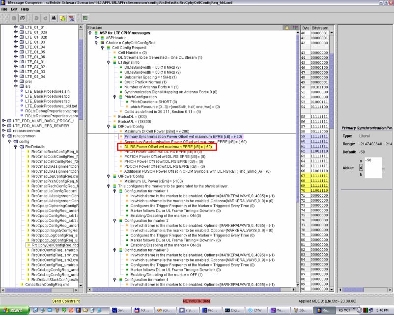
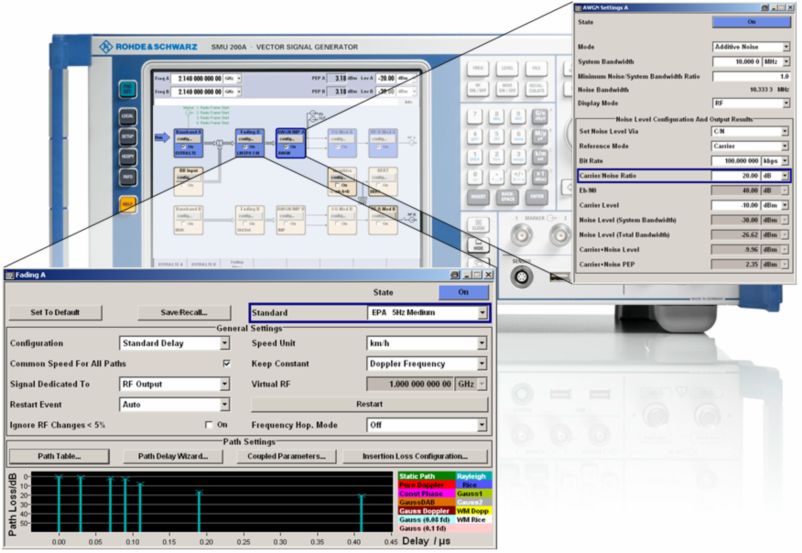
Table of Contents

                Table of Contents
            1          Motivation ................................................................................... 4

            2          LTE cell search and cell selection procedure .......................... 6
            2.1        LTE Initial Access ..............................................................................................6
            2.2        Initial synchronization.......................................................................................6
            2.2.1      Step I – Primary Synchronization Signal ........................................................7
            2.2.2      Step II – Secondary Synchronization Signal (SSS)......................................10
            2.3        Broadcast of essential system information in LTE ......................................15
            2.3.1      PBCH and MIB .................................................................................................15
            2.4        Difference between LTE FDD and TD-LTE.....................................................17
            2.5        Cell selection and reselection criteria...........................................................19

            3          R&S test solutions for LTE, focus cell search and selection 22
            3.1        Why test cell search and selection performance?.......................................22
            3.2        Downlink signal generation............................................................................23
            3.3        Downlink signal analysis ................................................................................24
            3.4        R&S® CMW500 – UMTS LTE Protocol Tester ...............................................26
            3.4.1      Introduction......................................................................................................26
            3.4.2      Operating software for protocol tests ...........................................................29
            3.4.3      Verification of cell-search & selection procedure with R&S® CMW500 ....29
            3.4.3.1 PHY scenarios – Physical Layer Testing ......................................................29
            3.4.3.2 IOT – Interoperability Testing .........................................................................30
            3.4.3.3 Cell selection and reselection according to 3GPP TS 36.523 Part 1..........33
            3.4.3.4 Cell selection and reselection according to 3GPP TS 36.521 Part 3..........34

            4          Abbreviations ........................................................................... 35

            5          Literature................................................................................... 36

            6          Additional Information ............................................................. 37

            7          Ordering Information ............................................................... 38

1MA150_0E                                        Rohde & Schwarz Cell search and cell reselection procedure in UMTS LTE 3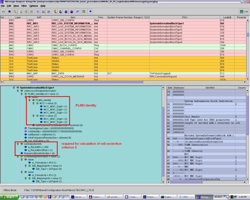
Motivation

                                                                                              LTE Initial Access

            1 Motivation
              Until now ,transmitter and receiver concepts for UMTS LTE have been proven by
              verifying downlink and uplink transmissions for base stations (enhanced NodeB and
              eNB) and terminals (User Equipment, UE). Measurements of parameters such as
              transmission power, modulation quality, or spectrum were performed. The results were
              then validated against the appropriate limits. Tolerances and measurements are
              specified in [1] and [2] and in [3] and [4] respectively. This process began with low-level
              block testing and was further increased to integrate all required functional blocks into
              the test setup.
              After passing the first basic test routines, the next major block of testing was started
              more or less in parallel. The focus was shifted to Layer 1 testing and especially to
              validating the physical layer procedures, which are described in [5]. The testing of the
              physical layer procedures can be categorized into data-path, functional and
              performance testing. With data-path testing, which is executed in an open-loop fashion,
              the correct implementation of the individual downlink and uplink channels is validated
              according to [6] and [7] is validated. In order to facilitate the debugging process,
              intermediate points within the encoding and decoding chains of the test equipment
              must be accessible by the test engineer. Once this test step is passed, functional
              testing begins. Within a controlled and static testing environment, procedures such as
              reporting the quality of the radio channel (Channel Quality Indicator, CQI) or validating
              the HARQ process for downlink and uplink data transmission are performed as
              specified in [5]. The procedures for scheduling can be used to test the HARQ process
              in both transmission directions.
              Performance testing verifies the performance of the device. In the first phase,
              transmitter and receiver performance are measured, and in the final phase the system
              performance including closed-loop operation and UE procedures are tested. One
              example from the performance requirements described and specified in [4] Section 8 is
              downlink data transmission on the Physical Downlink Shared Channel (PDSCH). The
              test engineer is interested in how the Block Error Rate (BLER) varies by changing
              signal power, type and level of interference, the chosen transport format and the
              fading-channel profiles [8].
              Before data-path and functional testing as well as system performance evaluation are
              performed, two essential physical layer procedures must be validated: cell search and
              cell selection as well as the random access procedure. Cell search is essential, since it
              ensures that the UE’s receiver is able to synchronize in both time and frequency to an
              LTE downlink signal. The Device Under Test (DUT) is than enabled to receive
              important parameters via the broadcasted system information. These parameters are
              necessary to establish uplink synchronization as well as to perform initial access to
              network. This procedure has already been used in previous technologies and is
              commonly known as random access. The random access procedure includes
              functionality from higher layers, such as the MAC and RRC layer, which increases
              complexity of this part of the testing.
              This application note explains the fundamentals of the cell search and cell selection
              process for both modes of LTE: FDD and TDD. It describes how to generate and
              analyze the required signals using Rohde & Schwarz test and measurement solutions
              for UMTS LTE. It also shows how to perform protocol tests according to the baseline of
              the required 3GPP specifications for the Single Input Single Output (SISO) and Multiple
              Input Multiple Output (MIMO) scenarios.
              This application note assumes basic knowledge of 3GPP LTE technology as provided
              in [9].

1MA150_0E                              Rohde & Schwarz Cell search and cell reselection procedure in UMTS LTE 4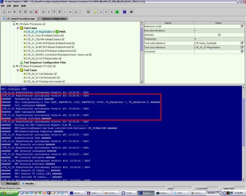
LTE cell search and cell selection procedure

                                                                                                                 LTE Initial Access

             2 LTE cell search and cell selection
               procedure

            2.1 LTE Initial Access
                Like all mobile communication systems, in LTE a terminal must perform certain steps
                before it can receive or transmit data. These steps can be categorized in cell search
                and cell selection, derivation of system information, and random access. The complete
                procedure is known as LTE Initial Access and is shown in Figure 1. After the initial
                access procedure, the terminal is able to receive and transmit its user data.

                Figure 1: LTE Initial Access: cell search and cell selection

            2.2 Initial synchronization
                Successful execution of the cell search and selection procedure as well as acquiring
                initial system information is essential for the UE before taking further steps to
                communicate with the network. For this reason, it is important to take a closer look at
                this fundamental physical layer procedure. This section focuses on the cell-search
                scheme defined for LTE and the next chapter describes reception of the essential
                system information.
                As in 3G (WCDMA), LTE uses a hierarchical cell-search procedure in which an LTE
                radio cell is identified by a cell identity, which is comparable to the scrambling code
                that is used to separate base stations and cells in WCDMA. To avoid the need for
                expensive and complicated network and cell planning, 504 physical layer cell identities
                of is sufficiently large. With a hierarchical cell search scheme, these identities are
                divided into 168 unique cell layer identity groups in the physical layer, in which each
                group consists of three physical layer identities1. To remember this hierarchical

                                                      1     (1)               (2)                                      (1)     (2)
                                                          N ID  = 0…167 and N ID                             cell
                                                                                  = 0, 1, 2; cell identity N ID   = 3N ID  + N ID

1MA150_0E                                     Rohde & Schwarz Cell search and cell reselection procedure in UMTS LTE 5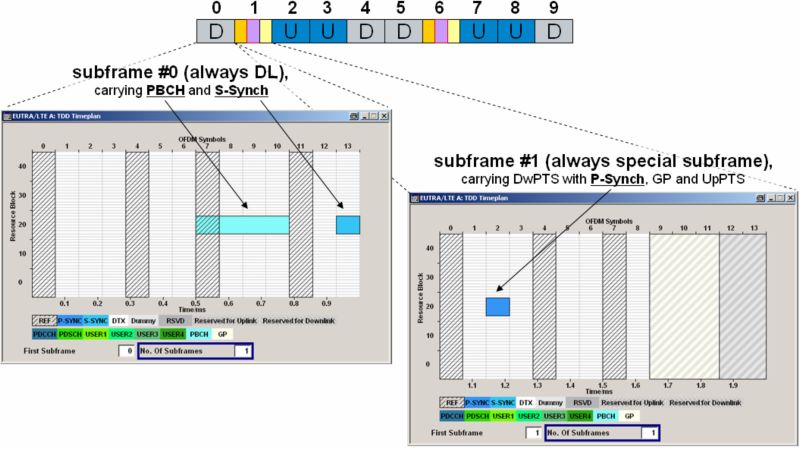
LTE cell search and cell selection procedure

                                                                                                        Initial synchronization

                  principle, consider the example of first names and surnames. According to statistics2,
                  the most common English surname is “Smith”, which corresponds to physical layer cell
                  identity group 0. The second most common surname is “Johnson”, which represents
                  the physical layer cell identity group 1. This example can be extended to the last group,
                  which would be “Rose”. The most common male first names are “James”, “John”, or
                  “Robert” and female names are “Mary”, “Patricia”, and “Linda”. Each first name
                  represents one of the three physical layer identities.
                  This information is now transmitted using two different signals, generated by Layer 1.
                  The two signals, carrying the physical layer identity and the physical layer cell identity
                  group, are the primary and the secondary synchronization signals respectively. This
                  means that the complete cell search procedure consists of two steps to identify the
                  cells’ identity. The process is shown graphically in Figure 2.

                  Figure 2: Physical layer cell identity and synchronization signals

            2.2.1 Step I – Primary Synchronization Signal

                  The UE first looks for the primary synchronization signal (PSS) which is transmitted in
                  the last OFDM symbol of the first time slot of the first subframe (subframe 0) in a radio
                  frame. This enables the UE to acquire the slot boundary independently from the
                  chosen cyclic prefix selected for this cell. Based on the downlink frame structure (Type
                  1, FDD), which is shown in Figure 6, the primary synchronization signal is transmitted
                  twice per radio frame, so it is repeated in subframe 5 (in time slot 11). This enables the
                  UE to get time synchronized on a 5 ms basis, which was selected to simplify the
                  required inter-frequency and inter-RAT measurements. LTE must accommodate
                  handover to and from other radio access technologies, such as GSM/GPRS/EDGE,
                  WCDMA/HSPA or CDMA®2000 1xRTT/1xEV-DO.
                  In the frequency domain, six resource blocks (RB) around the DC subcarrier are
                  reserved for transmission of the synchronization signals. In the frequency domain, an
                  RB is formed by 12 subcarriers. With a subcarrier spacing of 15 kHz a bandwidth of
                  180 kHz (12*15 kHz) is occupied, reserving a frequency range of 1.08 MHz (6*180
                  kHz) around the center frequency for transmission of synchronization signals (that is,
                  72 subcarriers). This is independent from the defined channel bandwidth that is

                                                        2
                                                            http://names.mongabay.com/data/1000.html (visited in 2009-08)

1MA150_0E                                      Rohde & Schwarz Cell search and cell reselection procedure in UMTS LTE 6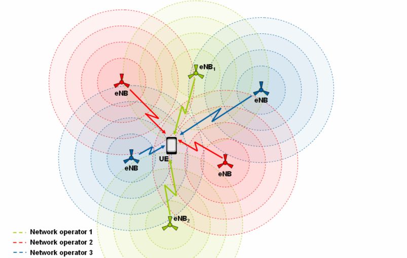
LTE cell search and cell selection procedure

                                                                                                                           Initial synchronization

            configured for the cell3. The type of signal used for primary synchronization is a Zadoff-
            Chu (ZC) sequence. ZC sequences are CAZAC sequences, which stands for Constant
            Amplitude Zero Auto Correlation and describes the characteristic of this type of
            sequences. With a constant amplitude, a low peak-to-average power ratio is achieved,
            where zero auto correlation equates with good time domain behavior. Since the
            primary synchronization signal uses only 62 of the 72 reserved subcarriers, the
            required length NZC of the Zadoff-Chu sequence is given as NZC=634. The reason 62
            rather than 72 of the reserved subcarriers are used is because it enables the UE to use
            a 64 Fast Fourier Transform (FFT) and lower sampling rate. This approach helps to
            approximate the vendor-specific implementations of an estimation algorithm and
            simplifies the entire procedure. In the case of TD-LTE, it also avoids correlation with
            the uplink demodulation reference signals that use the same kind of sequence as the
            PSS. Equation 1 shows how to generate the ZC sequence used as the primary
            synchronization signal.

            Equation 1: Generating the primary synchronization signal [1]

                                           un ( n +1)
                                      j                             n =0 ,1,..., 30

            d u (n ) =        e              63
                                          un ( n +1)( n + 2 )
                                  j                                n =31, 32 ,..., 61
                          e                      63

            The root index u in Equation 1 depends on the selected physical layer identity. For
             N ID( 2 ) = 0 the root index used is 25, for N ID( 2 ) = 1 it is 29, and for N ID( 2 ) = 2 the index is 34.
            Root indices define a ZC sequence from a set of ZC sequences available with the
            required sequence length NZC. The root index u also indicates the maximum number of
            sequences available with a certain length NZC. For the PSS, the basis is the two
            sequences 25 (= n1) and 29 (= n2). The third index is derived by subtracting NZC – n2 (=
            63–29 = 34). The reason for selecting n1 and n2 depends on the very good conjugate-
            complex symmetry of these two sequences in the time domain. This reduces the
            processing effort required for synchronization and the sequences based on indices n1
            and n2 show the best auto-correlation and cross correlation properties.
            Mapping of the selected sequence to the reserved subcarrier depends on the frame
            structure type and thus on the LTE mode. For FDD frame structure Type 1 the
            sequence is mapped according to Equation 2.

            Equation 2: Mapping of primary synchronization signal to resource elements (k, l) [1]

            a k ,l = d (n),                    n = 0,1, ..., 61
                                  N N SCRBDL

            k = n 31 +                     ,
                                          RB
                                                                l = N Symbol
                                                                      DL
                                                                             1
                                    2

            Figure 3 shows the PSS in the constellation diagram using signal analysis performed
            with R&S® FSQ-K100 software option. With help of the evaluation filter, the
            constellation diagram can be shown for specific resource elements (k, l) – in this

                                                                           3
                                                                            Channel bandwidths of 1.4, 3, 5, 10, 15 or 20 MHz are supported in
                                                                           3GPP UMTS LTE.
                                                                           4
                                                                               62 subcarrier and 1 (un-used) DC subcarrier; which is punctured

1MA150_0E                                                       Rohde & Schwarz Cell search and cell reselection procedure in UMTS LTE 7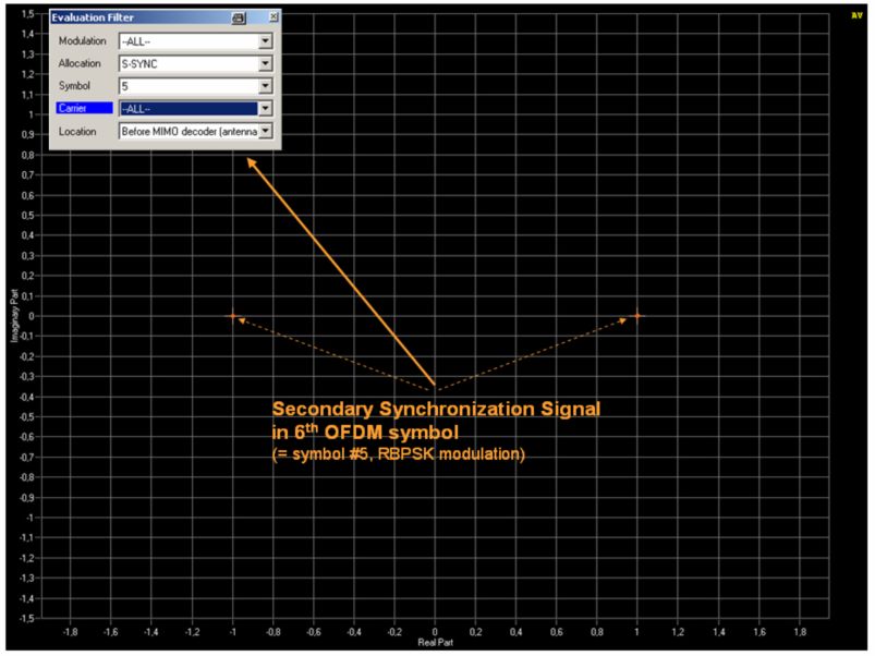
LTE cell search and cell selection procedure

                                                                                           Initial synchronization

            example the 31st subcarrier left of the DC subcarrier (k = -31) and in the 6th OFDM
            symbol (l = 6).

            Figure 3: Primary synchronization signal (R&S®FSQ-K100 EUTRA/LTE downlink/BS analysis)

            The unit circle represented by the dotted line marks the constant amplitude of the
            sequence. The excellent auto-correlation properties can be monitored by looking at the
            different subcarriers, carrying the sequence one-by-one. The dot seems to move
            randomly on the unit circle when changing the subcarriers, as the distance between
            the positions is not equidistant. This kind of hopping is unique to each sequence and
            depends on the root indices u. Figure 4 shows the primary synchronization signal for
            the three different indices. An LTE downlink signal fully compliant with 3GPP Release
            8 can be generated with the R&S® SMU200A vector signal generator.

1MA150_0E                             Rohde & Schwarz Cell search and cell reselection procedure in UMTS LTE 8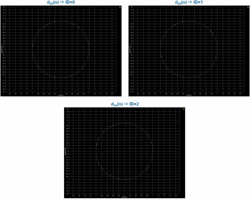
LTE cell search and cell selection procedure

                                                                                                   Initial synchronization

                  Figure 5: Primary synchronization signal (ID=0, ID=1 and ID=2)

                  The matched filtering works generally in this way so that the received signal is
                  correlated with the possible sequences for the PSS. This procedure is not executed on
                  the received analog RF signal, but rather in the digital domain. The possible sequence
                  (e.g. “James”, ID=0) is multiplied by the received pattern, and the operation must be
                  synchronized to the clock. A subsequent integrator adds up the signal, and if the output
                  agrees with the checked sequence a rising, positive ramp is produced. This indicates
                  that the tested sequence is the sequence used for the PSS. In another example, the
                  next sequences (e.g. “John”, ID=1; “Robert”, ID=2) is multiplied by the pattern.
                  With successful matched filtering, the device has identified the physical layer identity
                  for this cell as well as 5 ms timing. It can later execute the next step, which is looking
                  for the secondary synchronization signal and the physical layer cell identity group to
                  compute the cells’ identity.

            2.2.2 Step II – Secondary Synchronization Signal (SSS)

                  After the mobile has found the 5 ms timing, the second step is to obtain the radio frame
                  timing and the cells’ group identity. This information can be found from the SSS. In the
                  xtime domain, the SSS is transmitted in the symbol before the PSS . The SSS also
                  has 5 ms periodicity, which means it is transmitted in the first and sixth subframes
                  (subframes 0 and 5) as shown in Figure 6. Like the PSS, the SSS is transmitted on 62
                  of the 72 reserved subcarriers around the DC subcarrier.

1MA150_0E                                     Rohde & Schwarz Cell search and cell reselection procedure in UMTS LTE 9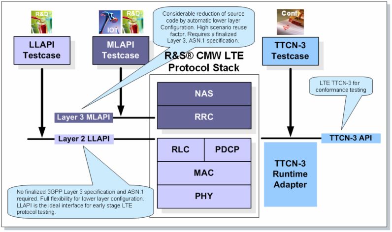
LTE cell search and cell selection procedure

                                                                                             Initial synchronization

            Figure 6: Downlink frame structure type 1 (LTE FDD) with synchronization signals (P-Synch, S-
            Synch)

            The SSS is represented by an interleaved concatenation of two length-31 binary
            sequences that are scrambled with a sequence that depends on the physical layer
            identity ( N ID( 2 ) )as the PSS . It is always a pair of sequences ( s0(m0 ) , s1(m1 ) ), which is
            transmitted in a subframe. Sequence s 0(m0 ) is mapped in the case of subframe 0 to the
            even numbered subcarriers ( d (2n) ), whereas sequence s1(m1 ) is mapped to odd
            numbered subcarriers ( d (2n + 1) ). For subframe 5 it is the other way around. Figure 7
            shows the sequences used for the secondary synchronization signal and their mapping
            for subframe 0.

            Figure 7: Mapping of secondary synchronization signal to 62 subcarriers for subframe 0

            The combination of the indices m0 and m1 defines the physical layer cell identity
            group N ID(1) , and the possible combinations of m0 and m1 for the 168 groups (“Smith”,
            “Johnson”, …) are defined in [6]. Depending on the subcarrier – even or odd – another
            scrambling sequence is used for sequences s 0(m0 ) , s1(m1 ) . In case of d (2n) , the
            scrambling sequence employed is c0 (n) , for d (2n + 1) it is c1 (n) . Depending on the
            subframe in which d (2n + 1) is transmitted, an additional scrambling sequence is used.
            For subframe 0 it is z1(m0 ) (n) , and for subframe 5 z1(m1 ) (n) is used. Each of these two
            scrambling sequences depends on the indices m0 and m1 , which define the physical
            layer cell identity group. Scrambling with an additional scrambling sequence optimizes
            cell search at the cell edge. Here the UE receives signals of several eNBs. At this point

1MA150_0E                              Rohde & Schwarz Cell search and cell reselection procedure in UMTS LTE 10
LTE cell search and cell selection procedure
Initial synchronization
differentiation is required, which is achieved using a cell-identity-dependent scrambling
sequence such as z1(m0 ) (n) and z1(m1 ) (n) .
Equation 3: Generation of secondary synchronization signal according to [6]
s 0 ( m 0 ) ( n )c 0 ( n ) in subframe 0
d (2n ) = ( m1)
0 n 30
s1 ( n) c 0 ( n ) in subframe 5
s1 ( m1) (n)c1(n) z1 ( m 0 ) (n) in subframe 0
d (2n + 1) = ( m0) ( m1)
0 n 30
s0 (n)c1(n) z1 ( n) in subframe 5
Figure 8 shows the SSS in the constellation diagram using the R&S® FSQ-K100
EUTRA/LTE downlink/BS analysis software option.
Figure 8:Secondary synchronization signal in the constellation diagram
By exploiting the property that the combination of s 0( m0 ) , s1( m1 ) transmitted in subframes 0
and 5 is an allowable pair representing the SSS, the terminal can resolve the ambiguity
resulting from the previous step and determine the frame timing as well as physical
layer cell identity group. Knowing this, the UE can determine the cells’ unique identity
using N IDcell = 3 N ID(1) + N ID( 2 ) , which shows that the calculation of cells identity is based on a
modulo-3 operation. The determination of the cells’ identity enables the UE to examine
the pseudo-random sequence used to generate the cell-specific reference signals as
1MA150_0E Rohde & Schwarz Cell search and cell reselection procedure in UMTS LTE 11LTE cell search and cell selection procedure
Initial synchronization
the initialization of the PRS generator based on N IDcell and the used cyclic prefix (CP):
normal or extended.
Equation 4: Initialization PRS generator used generating the cell-specific reference signal pattern [1]
0 for normal CP
(
cinit = 210 (7 (ns + 1) + l + 1) 2 N ID
cell
)
+ 1 + 2 N ID
cell
+ N CP N CP =
1 for extended CP
The UE is thus able to become fully synchronized with the radio cell because the
reference signals are transmitted in well-defined resource elements. In every sixth
subcarrier in the frequency domain a reference symbol from the generated reference
signal pattern is transmitted. In the time domain, every fourth OFDM symbol transmits
a reference symbol . A resource block contains four reference symbols. Figure 9
shows reference signal pattern for two antennas.
Figure 9: LTE downlink reference signals
With increasing numbers of antennas the number of unused resource elements
increases as well, and the signaling overhead is increased. Nevertheless, when using
four transmitting antennas the number of reference symbols is reduced for antenna
ports 2 and 3. This is a trade-off between MIMO performance and the overhead
generated by the required reference signal pattern per antenna. Figure 10 shows the
reference signal pattern for up to four antennas.
1MA150_0E Rohde & Schwarz Cell search and cell reselection procedure in UMTS LTE 12LTE cell search and cell selection procedure
Initial synchronization
Figure 10: Reference signal pattern for up to four transmitting antennas
The downlink reference signals help the terminal distinguish between the different
transmission antennas. Where one antenna is transmitting the reference pattern the
other antennas are transmitting nothing. These physical signals are also used to
estimate the quality of the radio channel. The network submits the power level to the
device that reference signals transmit, and the terminal measures this power level. The
difference corresponds to a Channel Quality Indicator (CQI) that is given to the
network. This CQI value provides transport format and modulation scheme information
to the base station, at which the transport block error probability at the terminal side
would not exceed 10%.
Figure 11 shows power over time, displaying the averaged power level for reference
signals and synchronization signals.
Figure 11: Power vs. time LTE FDD downlink signal showing P-, S-Synch and reference signals
1MA150_0E Rohde & Schwarz Cell search and cell reselection procedure in UMTS LTE 13LTE cell search and cell selection procedure
Broadcast of essential system information in LTE
Figure 12 shows the power spectrum of a 20 MHz LTE downlink signal with PSS and
SSS signals as well as reference signals transmitted on certain resource elements as
described above.
Figure 12: Power spectrum LTE FDD downlink signal, 20 MHz with P-, S-Synch and reference signals
But from what does the UE determine the bandwidth of, for example, 20 MHz?
2.3 Broadcast of essential system information in LTE
2.3.1 PBCH and MIB
After the successful execution of the cell-search procedure described in the previous
section, the device is able to decode the Physical Broadcast Channel (PBCH) and read
out the Master Information Block (MIB). As shown in Figure 13, the PBCH is
transmitted in the first four OFDM symbols of the second time slot of the first subframe.
The periodicity is 40 ms, which means that the MIB is transmitted every fourth radio
frame. The PBCH is scrambled prior to modulation with a cell-specific sequence that
depends on the cells’ identity N IDcell . In contrast to the synchronization signals, the
PBCH is transmitted on the 72 reserved subcarriers, which are QPSK-modulated.
1MA150_0E Rohde & Schwarz Cell search and cell reselection procedure in UMTS LTE 14LTE cell search and cell selection procedure
Broadcast of essential system information in LTE
Figure 13: Synchronization signals, broadcast channel and downlink frame structure (Type 1, FDD)
As in 3G networks, system information in LTE is separated into the MIB and a number
of System Information Blocks (SIBs). This classification as well as a high-level
description of the carried information is shown in Figure 14. The color code highlights
as an example the system information with relevance for the random access procedure
(SIB Type 2, purple-colored) respectively which is a prerequisite (MIB and SIB Type 1,
blue-colored) before the required parameter for this procedure can be extracted.
Figure 14: Classification of system information in LTE
For cell search and selection the UE reads the PBCH and extracts the information from
the MIB. The MIB carries the most essential system information, which is submitted by
the logical Broadcast Control Channel (BCCH) via the Broadcast Channel (BCH)
mapped onto the PBCH. The device is informed about the transmission bandwidth by
transmitting the number of available resource blocks. This indicates the overall channel
bandwidth, which for this radio cell is configured as 100 RB that corresponds to 20
MHz [1]. The configuration of Physical HARQ Indicator Channel (PHICH) and the
System Frame Number (SFN) are the other types information carried by the MIB.
Other essential information is the number of used transmission antennas on the eNB
side, of which the terminal is not directly informed . In fact, this information is derived
from the sequence in which one of the CRC bits is scrambled and is added to each
1MA150_0E Rohde & Schwarz Cell search and cell reselection procedure in UMTS LTE 15LTE cell search and cell selection procedure
Difference between LTE FDD and TD-LTE
transport block. The generation of the PBCH as well as the bit sequence indicating the
number of transmit antennas is shown in Figure 15.
Figure 15: Generation of Physical Broadcast Channel (PBCH); number of TX antennas
Based on the bandwidth information, the terminal is able to calculate the position of the
reference symbols frequency-wise as they are transmitted every fourth OFDM symbol
(from a time-domain perspective) . That enables the UE to get fully synchronized to the
time and frequency domain.
Figure 16 shows the constellation diagram for a downlink signal with just the PSS and
SSS and reference signals present as well as the PBCH.
Figure 16: Constellation diagram LTE FDD DL signal with P-, S-Synch, reference signal and PBCH
2.4 Difference between LTE FDD and TD-LTE
The essential LTE TDD parameters are given in [9]. In the case of cell search, the
position of the synchronization signals is different than in LTE FDD. The primary
synchronization signal is always transmitted in the second subframe (subframe 1) in
the third OFDM symbol (symbol 2). As the repetition rate for synchronization signals is
in TD-LTE the same as for LTD FDD (i.e., 5 ms), the PSS is again transmitted in
subframe 6, which is a special subframe with Downlink Pilot Time Slot (DwPTS),
Guard Period and Uplink Pilot Time Slot (UpPTS), or a subframe directly assigned for
downlink transmission. The secondary synchronization is instead transmitted in the first
1MA150_0E Rohde & Schwarz Cell search and cell reselection procedure in UMTS LTE 16LTE cell search and cell selection procedure
Difference between LTE FDD and TD-LTE
subframe in time slot 1, OFDM symbol 13 when a normal cyclic prefix is used. The
Physical Broadcast Channel is the as LTE FDD as well. This one is transmitted in the
first four OFDM symbols of the second time slot in the first subframe.
Figure 17 assumes UL-DL Configuration 1 and shows the position of PSS and SSS
signals as well as PBCH using the TDD time plan available in the R&S® SMU200A
vector signal generator.
Figure 17: P-, S-Synch and PBCH position for TD-LTE
Figure 18 shows power over time for TD-LTE for the first subframe. The differences
between it and FDD (Figure 11) for the position of the signal components can be
extracted directly in the measurement results.
Figure 18: Power versus time; TD-LTE, subframe 0
1MA150_0E Rohde & Schwarz Cell search and cell reselection procedure in UMTS LTE 17LTE cell search and cell selection procedure
Cell selection and reselection criteria
2.5 Cell selection and reselection criteria
The previous section described how initial cell selection will work and the difference
between LTE FDD and TD-LTE. However, only when specific criteria are fulfilled is the
UE allowed to camp on that cell. These criteria for cell selection as well as cell
reselection for LTE are specified in [10].
It is further illustrated by a description of the two procedures: In the initial cell selection
procedure, as described in the previous sections, no knowledge about RF channels
carrying an E-UTRA signal is available at the UE. In that case the UE scans the
supported E-UTRA frequency bands to find a suitable cell. Only the cell with the
strongest signal per carrier will be selected by the UE. The second procedure relies on
information about carrier frequencies and optionally cell parameters received and
stored from previously-detected cells. If no suitable cell is found using the stored
information the UE starts with the initial cell selection procedure.
S is the criterion defined to decide if the cell is still suitable . This criterion is fulfilled
when the cell selection receive level is Srxlev > 0. Srxlev is computed based on Equation
5.
Equation 5: Srxlev, PCompensation estimation [10]
Srxlev = Q rxlevmeas (Q rxlevmin + Q rxlevminoffset ) PCompensation [dB]
where PCompensation = max(PEMAX - PUMAX , 0) [dB]
• Qrxlevmeas is the measured receive level value for this cell, i.e. the Reference
Signal Received Power (RSRP) as defined in [11]. This measured value is the
linear average over the power of the resource elements that carry the cell-
specific reference signals over the considered measurement bandwidth.
Consequently, it depends on the configured signal bandwidth. In the case of
receiver diversity configured for the UE, the reported value will be equivalent to
the linear average of the power values of all diversity branches.
• Qrxlevmin is the minimum required receive level in this cell, given in dBm. This
value is signaled as Q-RxLevMin by higher layers as part of the System
Information Block Type 1 (SIB Type 1). Qrxlevmin is calculated based on the
value provided within the information element (-70 and -22) multiplied with
factor 2 in dBm.
• Qrxlevminoffset, is an offset to Qrxlevmin that is only taken into account as a result of
a periodic search for a higher priority PLMN while camped normally in a Visitor
PLMN (VPLMN). This offset is based on the information element provided
within the SIB Type 1, taking integer values between (1…8) also multiplied by
a factor of 2 in dB. This gives a wider range by keeping the number of bit
transmitting this information. The offset is defined to avoid “ping-pong”
between different PLMNs. If it is not available then Qrxlevminoffset is assumed to
be 0 dB.
1MA150_0E Rohde & Schwarz Cell search and cell reselection procedure in UMTS LTE 18LTE cell search and cell selection procedure
Cell selection and reselection criteria
• PCompensation is a maximum function as shown in Equation 5. Whatever
parameter is higher, PEMAX-PUMAX or 0, is the value used for PCompensation. PEMAX
[dBm] is the maximum power a UE is allowed to use in this cell, whereas PUMAX
[dBm] is the maximum transmit power of an UE according to the power class
the UE belongs too. At the moment only one power class is defined for LTE,
which corresponds to Power Class 3 in WCDMA that specifies +23 dBm. PEMAX
is defined by higher layers and corresponds to the parameter P-MAX defined
in [11]. Based on this relationship, PEMAX can take values between -30 to +33
dBm. Only when PEMAX > +23 dBm PCompensation is it considered when
calculating Srxlev. The P-MAX information element (IE) is part of SIB Type 1 as
well as in the RadioResourceConfigCommon IE, which is part of the SIB Type
2.
As explained above, all parameters except for Qrxlevmeas are provided via system
information. In a real network a UE will receive several cells perhaps from different
network operators. The UE only knows after reading the SIB Type 1 if this cell belongs
to its operator’s network (PLMN5 Identity). First the UE will look for the strongest cell
per carrier, then for the PLMN identity by decoding the SIB Type 1 to decide if this
PLMN is a suitable identity. Afterwards it will compute the S criterion and decide for a
suitable cell or not.
Figure 19: Cell selection example
Figure 19 shows one possible scenario in a real network. Assume that the UE belongs
to network operator 1 (green). There are two other carriers also operating an LTE
network but of course at different frequencies. The terminal receives all base stations
but at different power levels. Based on the above definition the UE will select the
strong cell for each carrier . Using this the UE will start with network operator 3 and
figure out after decoding the SIB Type 1 that the PLMN saved on the USIM does not
match to the transmitted one. From this information it will stop with its attempt and
5
PLMN – Public Mobile Network Identity
1MA150_0E Rohde & Schwarz Cell search and cell reselection procedure in UMTS LTE 19LTE cell search and cell selection procedure
Cell selection and reselection criteria
proceed to the next strongest signal, which is operator 2 (red). Now the PLMN does
not correspond so the UE will continue with signal 3 (green) – and the PLMN will
match. The UE continues to use the information in SIB Type 1 and Type 2 to compute
the cell selection criteria. In this example, the parameters transferred and belonging to
eNB1 do not fulfill S > 0 where the UE will move along with demodulating and decoding
the information provided by eNB2. S > 0 is fulfilled and the UE starts camping on this
cell.
1MA150_0E Rohde & Schwarz Cell search and cell reselection procedure in UMTS LTE 20R&S test solutions for LTE, focus cell search and selection
Why test cell search and selection performance?
3 R&S test solutions for LTE, focus cell
search and selection
3.1 Why test cell search and selection performance?
Cell search and selection is an essential procedure and the basis of every interaction
between terminal and network. Beside detecting and selecting a cell during initial
access, cell search is used for LTE mobility purposes. It is a key requirement that the
UE not exceed a defined threshold when a new cell is being detected and report this to
the serving eNB. In terms of reporting, the UE measures the Reference Signal
Received Power (RSRP) as well as Reference Signal Reported Quality (RSRQ).
Figure 20: Cell search procedure
The RSRP is comparable to the CPICH RSCP measurement in WCDMA. This
measurement of the signal strength of an LTE cell helps to rank between the different
cells as input for handover and cell reselection decisions. The RSRP is the average of
the power of all resource elements which carry cell-specific reference signals over the
entire bandwidth. It can therefore only be measured in the OFDM symbols carrying
reference symbols.
The RSRQ measurement provides additional information when RSRP is not sufficient
to make a reliable handover or cell reselection decision. RSRQ is the ratio between the
RSRP and the Received Signal Strength Indicator (RSSI), and depending on the
measurement bandwidth, means the number of resource blocks. RSSI is the total
received wideband power including all interference and thermal noise. As RSRQ
combines signal strength as well as interference level, this measurement value
provides additional help for mobility decisions.
1MA150_0E Rohde & Schwarz Cell search and cell reselection procedure in UMTS LTE 21R&S test solutions for LTE, focus cell search and selection
Downlink signal generation
Formula 6: Reference signal receive quality
RSRP
RSRQ = N [dB ]
RSSI
N: Number of Resource Blocks
Assume that only reference signals are transmitted in a resource block, and that data
and noise and interference are not considered. In this case RSRQ is equal to -3 dB. If
reference signals and subcarriers carrying data are equally powered, the ratio
corresponds to 1/12 or -10.79 dB. At this point it is now important to prove that the UE
is capable of detecting and decoding the downlink signal under bad channel
conditions, including a high noise floor and different propagation conditions that can be
simulated by using different fading profiles.
3.2 Downlink signal generation
The R&S® SMU200A vector signal generator can be used to generate any kind of LTE
downlink signal: FDD as well as TDD. This signal can be used to stimulate for example
an UE’s receiver chain. By setting different power values for the synchronization and
reference signals, the UE receiver design can be stressed and tested to detect the
signal, get synchronized, and properly decode information such as cell identity. Adding
noise and real-time fading as defined by the fading profiles for LTE within 3GPP, the
tests can be further enhanced to make them more closely resemble actual operating
conditions.
1MA150_0E Rohde & Schwarz Cell search and cell reselection procedure in UMTS LTE 22R&S test solutions for LTE, focus cell search and selection
Downlink signal analysis
Figure 21: R&S® SMU200A vector signal generator applying fading and noise to an LTE DL signal
3.3 Downlink signal analysis
For testing the transmitter of an eNB, the R&S® FSQ signal analyzer is one of the
various choices Rohde & Schwarz is offering for LTE signal analysis. The instrument
offer various possibilities to prove the quality of the generated downlink signal and its
components required for cell search and selection for LTE FDD and TDD.
Figure 22 shows the analysis (signal flow and power spectrum) of an LTE downlink
signal with the R&S® FSQ-K100 EUTRA/LTE downlink/BS analysis option that can be
used as remote control software or as an option for inclusion in the instrument.
1MA150_0E Rohde & Schwarz Cell search and cell reselection procedure in UMTS LTE 23R&S test solutions for LTE, focus cell search and selection
Downlink signal analysis
Figure 22: Checking signal flow and power spectrum with R&S® FSQ-K100, Part I
The downlink signal was generated with the SMU and fading (EPA 5 Hz low) and
AWGN were applied. In this example, 485 was selected as the cell identity ( N ID
(1)
= 161 ,
N ID = 2 ), and the power settings for the primary and secondary synchronization signal
( 2)
were lowered from the reference signal by 15 and 30 dB respectively. These settings
are shown in Figure 23.
Figure 23: Power versus time
Figure 24 shows the analysis of the signal with the same configuration but at a different
moment in time when fading is not affecting the center of the transmission so that
decoding is still possible (as shown by the signal flow). It can be seen that by applying
fading and noise to the signal testing complexity would increase. It would also stress
the receiver design and show the quality of the transmitter circuit.
1MA150_0E Rohde & Schwarz Cell search and cell reselection procedure in UMTS LTE 24R&S test solutions for LTE, focus cell search and selection
R&S® CMW500 – UMTS LTE Protocol Tester
Figure 24:Checking signal flow and power spectrum with R&S® FSQ-K100, Part II
3.4 R&S® CMW500 – UMTS LTE Protocol Tester
The R&S® CMW500 LTE Protocol Tester can be used for verifying that the UE
performs cell search and selection compliant with the 3GPP specification for UMTS
LTE FDD now and later TDD. The validation of the cell-search procedure is described
in Section 3.4.3 of this application note and the CMW500 and required software tools
are described in the following sections.
3.4.1 Introduction
By simply adding options to the R&S® CMW500 wideband radio communication tester
(Figure 25), the instrument can be expanded to make it a powerful UMTS LTE protocol
tester.
1MA150_0E Rohde & Schwarz Cell search and cell reselection procedure in UMTS LTE 25R&S test solutions for LTE, focus cell search and selection
R&S® CMW500 – UMTS LTE Protocol Tester
Figure 25: R&S® CMW500 UMTS LTE protocol tester
Depending on the integration of the protocol layers, various approaches for performing
protocol tests can be used. The unit simulates an LTE radio access network for the
development and testing of chipsets as well as wireless devices, covering every stage
from development to conformance tests. The CMW500 offers various interfaces to
enable testing via an RF connection or in future via a digital baseband I/Q interface
(Figure 26). In addition, if a Layer 1 implementation is not yet provided or if integration
has not yet been performed, the LTE virtual test software (for PC) from Rohde &
Schwarz can be used to test just the protocol software. The LTE virtual test software
emulates the behavior of the radio protocol layers at the network end and an abstract
Layer 1 is used. The software sets up an IP connection to the protocol stack to be
tested. It then runs through special signaling test scenarios that verify the behavior of
the protocol stack at the wireless device end. All essential functions of the Layer 2 and
Layer 3 protocols have been implemented.
1MA150_0E Rohde & Schwarz Cell search and cell reselection procedure in UMTS LTE 26R&S test solutions for LTE, focus cell search and selection
R&S® CMW500 – UMTS LTE Protocol Tester
Figure 26: R&S® CMW500 provides different interfaces to do protocol testing
Maximum flexibility must be provided for developing test scenarios so that numerous
aspects can be covered and complex sequences can be recorded. The CMW500
distinguishes between the low-level application programming interface (LLAPI) and
medium-level application programming interface (MLAPI), depending on whether the
interface accesses Layer 2 or Layer 3. The LLAPI offers direct access to protocol
Layers 1 and 2, which provides extra flexibility in programming the R&S CMW500.
Depending on the progress in the Layer 3 definition the MLAPI becomes an efficient
approach. The user need not bother with the configuration of Layer 1 and 2 as Layer 3
messages because the instrument handles that task automatically. The CMW500 can
be programmed using the testing and test control notation 3 (TTCN-3) programming
language. Signaling conformance test cases have been agreed by 3GPP written in this
programming language. In addition to test cases for RF and Radio Resource
Management (RRM), 3GPP agreed that numerous Layer 2, Layer 3, and non-access
stratum test cases should be written in this programming language. The R&S CMW500
has the required software tools for creating, implementing, and preparing these test
cases. Figure 27 shows the different programming interfaces for the R&S® CMW500.
1MA150_0E Rohde & Schwarz Cell search and cell reselection procedure in UMTS LTE 27R&S test solutions for LTE, focus cell search and selection
R&S® CMW500 – UMTS LTE Protocol Tester
Figure 27: Programming interfaces for R&S CMW500 (LLAPI, MLAPI and TTCN-3)
3.4.2 Operating software for protocol tests
The R&S® CMW500 comes with a number of software tools to develop test cases
based on LLAPI and MLAPI, to reconfigure, run, and manage test campaigns, and to
analyze test results. The same software tools are reused for the CMW500 as for the
Rohde & Schwarz CRTU-G/W protocol test platform . The test case development is
based on Microsoft Visual Studio (R&S® CMW-XT015 option). The other tools are the
R&S® Project Explorer, R&S® Message Analyzer, R&S® Message Composer
explained in the following sections, and R&S® Automation Manager. The automation
manager (R&S® CMW–KT014) is used to remotely control the DUT by using well-
defined AT commands. It can control other test equipment such as the R&S®
AMU200A baseband signal generator to apply 3GPP-defined fading profiles to the
signal as required for different RF or RRM test scenarios.
3.4.3 Verification of cell-search & selection procedure with R&S®
CMW500
3.4.3.1 PHY scenarios – Physical Layer Testing
The physical layer (PHY) testing scenarios available for the R&S® CMW500 verify the
cell-search and cell selection procedure to verify the ability of the design to receive the
downlink signal, synchronize to it, and extract the transmitted system information such
as bandwidth. This basic scenario can be executed for two modes using one
transmitting and one receiving antenna (SISO) as well as using more transmission and
reception antennas ((MIMO).
1MA150_0E Rohde & Schwarz Cell search and cell reselection procedure in UMTS LTE 28R&S test solutions for LTE, focus cell search and selection
R&S® CMW500 – UMTS LTE Protocol Tester
SISO
In the SISO scenario a downlink signal is generated using different bandwidths (e.g.
20, 10, 5, or 3 MHz) and cell identities (e.g. 10, 20, 30 and 40) as well as different
power levels (-20, -30, -40 and -50 dBm) to validate the receiver’s design. This
configuration is saved in a .xml file that can be edited and configured with the
message.
MIMO
In terms of control channels and the broadcast channel in the downlink MIMO equates
to transmit diversity (Tx diversity). In other words, the same information is transmitted
via the antenna ports but coded differently. Only in terms of user data transmission are
different data streams transmitted over the antenna ports. The terminal can distinguish
between the different antenna ports as each antenna is defined by its own reference
signal pattern. Primary and secondary synchronization signals are only available on
antenna port 0 – the first antenna.
3.4.3.2 IOT – Interoperability Testing
Conformance testing is an essential part of proving a terminal’s behavior according to
the current status of the related specification. Test cases are defined covering all
conformance aspects, RF performance, Radio Resource Management (RRM), for
mobility as well as protocol. For LTE, both certification organizations, the Global
Certification Forum (GCF) and PCS Type Certification Review Board (PTCRB), have
started related work. This work includes several RF and RRM as well as protocol test
cases, in which a specific percentage must be passed by the device to be certified by
the related organization. These test cases are based on the prose versions defined by
the 3rd Generation Partnership Project (3GPP). This work is ongoing and the target
date for completion is September 2009. In terms of protocol testing, the 3GPP
definition is translated by a programming language (TTCN6-3) to executable test cases
on validated test platforms such as the R&S® CMW500 LTE Protocol Tester. As there
is still much work to do, certification is planned to begin at the end of 2010. Several
network operators are planning a pre-commercial launch before that date.
Interoperability testing (IOT) is an adequate way to perform validation on a device until
official certification is started, and even at that time can complement the testing
strategy.
Rohde & Schwarz supports interoperability testing with three different packages on the
R&S® CMW500 . They combine different test cases developed by Rohde & Schwarz
that follow different aspects of testing.
CMW–KF502. This packages is called “Basic LTE Procedures” and provides
10 test cases. It includes basic RRC7 and NAS8 procedures, registration, EPS
bearer setup, detach, cell selection/reselection, GUTI reallocation, and TA
update.
CMW–KF503. This packages combines 20 different test cases for “EPS
Bearer Verification” allowing the activation and verification of EPS bearers,
SISO/MIMO bearers, multiple EPS bearer contexts, and the verification of the
‘Always on’ connectivity.
6
TTCN-3 – Testing and Test Control Notation 3
7
RRC – Radio Resource Control
8
NAS – Non-Access Stratum
1MA150_0E Rohde & Schwarz Cell search and cell reselection procedure in UMTS LTE 29R&S test solutions for LTE, focus cell search and selection
R&S® CMW500 – UMTS LTE Protocol Tester
CMW–KF504. As the standard has more evolved in terms of mobility, this
package will be made available as it provides 20 test cases for “Intra-LTE
Mobility and Handover”.
A fourth package, CMW–KF505, provides interoperability test cases that are defined
by the LTE/SAE Trial Initiative (LSTI). LSTI is an industry alliance with the goal of
ensuring interoperability and ensuring fast market entry for UMTS LTE.
Cell selection and reselection is the initial procedure in LTE and is therefore part of the
CMW–KF502 package. Cell selection is part of other test cases such as the one
verifying the registration of the UE to the network. The following screenshots are taken
from executing this test case. Figure 28 shows the R&S® project explorer (R&S®
CMW–KT010 option) after successful testing of the UE’s capability to register with the
simulated network. The red mark shows the configuration of the cell using cell identity
0, frequency band 4, and a bandwidth of 10 MHz. The project explorer is used to
manage the test campaign by setting up and controlling the hardware and software of
the R&S® CMW500. After configuration and execution of the test campaign the project
explorer generates the test report.
Figure 28: Test case ‘Registration’ out of CMW–KF502 package shown in the project explorer
When setting up the cell the system information is also configured. With help from the
message analyzer (R&S® CMW–KT011 option) the details of System Information
Block Type 1 can be displayed. The message analyzer is used to examine the test
results by decoding the message log files provided by the project explorer with the test
report. Figure 29 shows the content of SIB Type 1, where the PLMN identity is provided
1MA150_0E Rohde & Schwarz Cell search and cell reselection procedure in UMTS LTE 30R&S test solutions for LTE, focus cell search and selection
R&S® CMW500 – UMTS LTE Protocol Tester
as well as Qrxlevmin and Qrxlevminoffset. Both parameters influence the calculation of the cell
selection criterion S.
Figure 29: Message analyzer
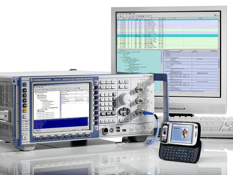
Another parameter influencing the calculation of the cell selection criterion is the power
level at which the Downlink Reference Signals (DL RS) are transmitted. This setting
can be configured using the message composer (R&S® CMW–KT012 option) by
editing the cell configuration file as shown in Figure 30. The message composer is
used to edit (for example) the Layer 3 messages as well as configuration files and is
therefore a convenient software tool to configure the test script.
1MA150_0E Rohde & Schwarz Cell search and cell reselection procedure in UMTS LTE 31R&S test solutions for LTE, focus cell search and selection
R&S® CMW500 – UMTS LTE Protocol Tester
Figure 30: Cell configuration shown with the Message Composer
3.4.3.3 Cell selection and reselection according to 3GPP TS 36.523 Part 1
Protocol conformance is specified in 3GPP TS 36.523 Part 1. Section 6.1.2. deals with
different aspects of testing the cell selection and reselection procedure in LTE. Ten test
cases have currently been defined.
As explained in the previous section, the prose version of the 3GPP specification is
translated by an ETSI related working group using a specific programming language
into executable TTCN-3 test cases. As of today9, the test cases covering cell selection
and reselection are available as code but have not been validated on any test platform.
This is because, except for one, all test cases deal with a multi-cell environment in
which up to three cells are simulated. Leading suppliers of test equipment are already
working on supporting these multiple cell scenarios.
Lets take a look at one particular test case, defined in section 6.1.2.2 in [14], which is
not requiring a multiple cell scenario. The purpose of this test case is to ensure that the
UE will not camp on a cell, which fulfils all requirements for a suitable cell except the
cell selection criteria S (S0). The power level for the cell-specific reference signal is
initially set to -95 dBm/15 kHz and later the level is increased to -75 dBm/15 kHz.
Based on the initial power level for the cell-specific reference signals, the UE should be
checked to ensure it does not perform any random access request. After 60 seconds
9
August 2009
1MA150_0E Rohde & Schwarz Cell search and cell reselection procedure in UMTS LTE 32R&S test solutions for LTE, focus cell search and selection
R&S® CMW500 – UMTS LTE Protocol Tester
the power level will be increased and the UE must recognize that the S criterion is now
met and should perform a random access.
Table 1 shows all the specific cell parameters for this particular test case.
Table 1: Cell selection, Qrxlevmin test case out of [13]
3.4.3.4 Cell selection and reselection according to 3GPP TS 36.521 Part 3
Part 3 of the UE conformance test specification covers the Radio Resource
Management (RRM), that is, mobility aspects [14]. As part of this cell selection more
cell reselection tests are defined for the two connected modes: IDLE or CONNECTED
state. In IDLE mode the actual baseline as of June 2009 and does not foresee any cell
selection tests. However, many cell reselection tests that do have as their main
purpose checking the terminal’s ability to reselect another radio access technology
when leaving LTE FDD or TDD coverage. These tests are valid only if the UE supports
this radio access technology.
The following technologies belong to the 3GPP technology evolution path: GSM as well
as UTRA FDD and UTRA TDD and also 3GPP2-defined technologies. As the majority
of CDMA2000® 1xRTT and 1xEV-DO carriers have announced their intention to
migrate to UMTS LTE, this 3GPP standard is likely to become the predominant mobile
broadband technology. This is also reflected in the test specification. Section 4.5 (for
HRPD cell re-selection) and 4.6 (for CDMA2000® 1xRTT cell re-selection) of [14] are
dealing with this aspect. In both cases the test purpose is to verify that the terminal is
capable of searching and measuring neighboring HRPD CDMA2000® 1xRTT cells and
comparing them to the E-UTRA serving cell to meet the inter-RAT cell re-selection
requirements. To perform those types of measurements, the UE must acquire the
timing of HRPD cells. This system time as well as the list of HRPD neighboring
frequencies (up to 16) and other relevant information are provided within System
Information Block Type 8 (SIB Type 8). A cell reselection priority is defined (0…7),
where 0 means lowest priority and 7 highest priority. Depending on the selected priority
and when the reception of the E-UTRA serving cell falls below a defined threshold, the
terminal will measure the CDMA2000 HRPD pilot strength at well defined time steps
[11, 14, 15].
1MA150_0E Rohde & Schwarz Cell search and cell reselection procedure in UMTS LTE 33Abbreviations
R&S® CMW500 – UMTS LTE Protocol Tester
4 Abbreviations
3GPP 3rd Generation Partnership Project
BCCH Broadcast Control Channel
CP Cyclic Prefix
CRC Cyclic Redundancy Check
DL Downlink
eNB E-UTRAN NodeB, enhanced Node B
EPRE Energy Per Resource Element
ETSI European Telecommunication Standardization Institue
E-UTRA Evolved UMTS Terrestrial Radio Access
E-UTRAN Evolved UMTS Terrestrial Radio Access Network
FDD Frequency Division Duplex
LTE Long Term Evolution
OFDM Orthogonal Frequency Division Multiplexing
OFDMA Orthogonal Frequency Division Multiple Access
PBCH Physical Broadcast Channel
PHY Physical Layer
PSS Primary Synchronization Signal
QPSK Quadrature Phase Shift Keying
RF Radio Frequency
RS Reference Signal
SISO Single Input Single Output
SSS Secondary Synchronization Signal
MIMO Multiple Input Multiple Output
TDD Time Division Duplex
TD-LTE TDD mode of LTE (= LTE TDD)
TTCN-3 Testing and Test Control Notation
UE User Equipment
UL Uplink
1MA150_0E Rohde & Schwarz Cell search and cell reselection procedure in UMTS LTE 34You can also read