Simultaneous Enhancement of Actuation Strain and Mechanical Strength of Nanoporous Ni-Mn Actuators
←
→
Page content transcription
If your browser does not render page correctly, please read the page content below
Research Article
www.advelectronicmat.de
Simultaneous Enhancement of Actuation Strain and
Mechanical Strength of Nanoporous Ni–Mn Actuators
Chuan Cheng,* Lukas Lührs, and Tobias Krekeler
functions, that work in either wet (liquid
Metallic electrochemical actuators convert electrical energy into mechanical electrolytes) or dry (solid electrolytes) envi-
energy via charge-induced strain at the nanoporous metal/electrolyte interface. ronments, under low operating voltages
≈1 V which is ≈3 orders less than com-
To enhance the actuation amplitude, a general choice is to increase the electrode
mercialized piezoelectric actuators.[1d,2]
surface area to elevate the charge capacity. However, a large surface area is det- Different from electric motors that are
rimental to the actuation stability and mechanical strength of the actuator, such composed of complex wheels and gears,
as irreversible volume shrinkage due to surface coarsening. Here, this critical an electrochemical actuator is usually a
issue can be mitigated by introducing a secondary actuation metal (Mn) into single piece of material, which enable it
the network of a primary actuation metal (Ni). A nanoporous Ni–Mn actuator is to be miniaturized and suitable for tasks
that are difficult or impossible to achieve
synthesized by chemical dealloying with a controllable Mn content by adjusting
by motors, such as artificial muscles,[3]
dealloying conditions. Mn enriched nanowires are entangled with much larger micro-fluid systems,[4] and electromechan-
sized Ni nanoligaments throughout the whole nanoporous network. Mn contrib- ical robots.[5] These actuation materials
utes a two-electron-transfer redox of Mn(OH)2/MnOOH/MnO2, which induces take advantage of the high surface-area-
reversible volume change via H+ intercalation/deintercalation. It is more efficient to-volume-ratio of nanoporous structures
and transform charge-induced interatomic
for strain generation than a one-electron-transfer redox of Ni(OH)2/NiOOH in
local strain into macroscopic volume
the host. A recorded high reversible strain of 1.94% is obtained. Simultaneously, change of the whole electrode,[1d,6] which
the mechanical strength of the actuator exponentially increases with the relative can even be observed with the naked eye,[7]
density due to the introduction of the secondary actuation metal. or lift a weight that was hundreds of times
heavier than the actuator itself.[1b,5]
Many immerging actuators are based on
soft materials for flexible applications,[8] such as carbon nano-
1. Introduction
tube/graphene sheets/yarns,[1a,2e,9] conducting polymers,[4,10]
Electrochemical actuation materials convert electrical energy 2D materials,[1b] and ionic polymer-metal composites;[11] while
into mechanical energy via charge-induced strain effect at the rigid and 3D bulk actuators, similar to those piezoelectric com-
nanoporous structured electrode/electrolyte interface during petitors, are rare and mainly nanoporous metal-based electro-
charge–discharge processes.[1] They have promising applica- chemical actuators, because of their high strength and stiff-
tions in micro-electromechanical systems for bio-inspired ness.[6,12] In the past two decades, researchers have spent plenty
of efforts to face critical challenges of metallic actuators to
Dr. C. Cheng, Dr. L. Lührs enhance the actuation strain from ≈0.1% to ≈1%,[1d,6,7b,13] elevate
Institute of Materials Physics and Technology charge–strain response rate against sluggish ion diffusion,[12b,14]
Hamburg University of Technology increase mechanical strength and stability against coarsening
21073 Hamburg, Germany
E-mail: Chuan.Cheng@warwick.ac.uk of metallic nano porous structures,[15] and replace precious
Dr. C. Cheng noble metals with low-cost transition-metals.[7a,13c,16]
Warwick Manufacturing Group However, there is a dead-lock problem that has not been
University of Warwick solved. On the one hand, a high specific surface area of the
Coventry CV4 7AL, UK metallic actuator is required to achieve large actuation strain,
Dr. T. Krekeler because the charge-induced strain is proportional to the specific
Electron Microscopy Unit
Hamburg University of Technology
capacity, and the high surface area is a pre-condition to store
21073 Hamburg, Germany more charges at the electrode/electrolyte interface either by
The ORCID identification number(s) for the author(s) of this article non-faradaic capacitance or by faradaic pseudocapacitance.[16d,17]
can be found under https://doi.org/10.1002/aelm.202100381. On the other hand, high specific surface area leads to mechan-
© 2021 The Authors. Advanced Electronic Materials published by ical weakness of the actuator, such as irreversible volume
Wiley-VCH GmbH. This is an open access article under the terms of shrinkage driven by the high surface-free-energy and low
the Creative Commons Attribution-NonCommercial-NoDerivs License, mechanical strength to bear and output the actuation load.[6,18]
which permits use and distribution in any medium, provided the original Therefore, even though the simultaneously high specific sur-
work is properly cited, the use is non-commercial and no modifications
or adaptations are made. face area and mechanical stability were regarded as critical for
metallic actuators to achieve competitive performances,[1d] these
DOI: 10.1002/aelm.202100381 two factors are difficult to coexist.
Adv. Electron. Mater. 2021, 7, 2100381 2100381 (1 of 12) © 2021 The Authors. Advanced Electronic Materials published by Wiley-VCH GmbH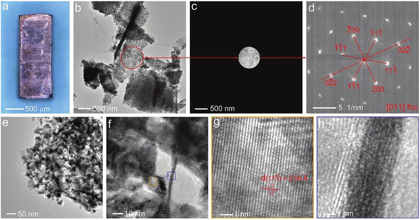
www.advancedsciencenews.com
www.advelectronicmat.de
This article demonstrates a different strategy to solve the 2. Results and Discussion
above problem which can enhance both actuation strain and
mechanical strength of metallic actuators at the same time. The Nanoporous Ni–Mn metal was synthesized by selectively
actuation strain is enhanced by a secondary and more effec- etching less noble metal Mn from a Ni30Mn70 precursor within
tive (higher capacitance) actuation metal in the nanoporous a weak acidic solution of (NH4)2SO4.[16b] The precursor was cast
network of a primary actuation metal, while the mechanical from pure Ni and Mn metals by an induction furnace in the
strength is increased because the secondary actuation metal Ar atmosphere. During dealloying, atoms of the more noble
increases the relative density of the porous structure. Here, we metal (Ni) aggregate into ligaments through a phase separa-
select transition-metal Ni–Mn composite as an example, which tion process and finally form a bi-continuous nanoporous
is synthesized by selectively etching of Mn from Ni30Mn70 pre- structure.[19,22] Due to the parting limit of dealloying,[19] Mn was
cursor. Due to the parting limit (dealloying threshold),[19] Mn is not completely removed and the residual Mn content was con-
not completely etched away and the residual Mn content can trolled by dealloying conditions, including acid concentration,
be controlled by dealloying conditions; importantly, residual temperature, and dealloying time (see later in Section 2.3).
Mn is homogeneously integrated and evenly distributed on a
3D interconnected Ni network realized by chemical dealloying.
Mn oxides/hydroxides grow on the metal surface during 2.1. Electron Microscopy Characterization of Nanoporous
charge–discharge, which exhibit super faradaic pseudocapaci- Ni–Mn
tance (e.g., 1380 F g−1 for MnO2),[20] and it is very promising
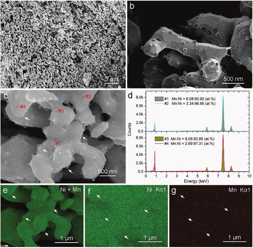
to generate high actuation strain. The primary actuation metal Figure 1a shows a typical as-dealloyed nanoporous metal that
Ni experiences Ni(OH)2/NiOOH redox reactions on the sur- has mm-scales in three dimensions. A scanning transmission
face and also induces strain due to lattice mismatch among electron microscopy (STEM) image of Figure 1b reveals a nano-
surface atoms.[21] 3D interconnected metal skeleton exists porous structure inside the sample. Figure 1c notices a circular
beneath the metal oxides/hydroxides layers, which provides a area for selected-area-diffraction (SEAD). The SEAD pattern in
highly electric conductive network to facilitate pseudocapacitive Figure 1d indicates a single-crystal within the selected area that
charge storage/release—important for the fast charge–strain contains hundreds of ligaments. The SEAD pattern shows char-
response.[20a,21a] Thus, this article reports a high-performance acteristic features of an fcc structured crystal with the electron
metallic muscle designed from a new strategy to simultane- beam along the [011] zone axis.[23] From the measurement of
ously enhance actuation strain and mechanical strength, com- the g 111 vector in the SEAD pattern, d(111) = 2.05 Å is obtained,
bined with a low-cost fabrication method. which is consistent with the d-spacing measured from the
Figure 1. Characterization of as-dealloyed nanoporous Ni–Mn metal. a) Optical image of a bulk as-dealloyed sample. b) STEM image of the sample
reveals nanoporous structures. c) A selected area (≈860 nm in diameter) for electron diffraction. d) The electron diffraction pattern indicates a single
and fcc structured crystal in the selected area, with the electron beam along the [011] zone axis. e,f) Enlarged STEM images of the nanoporous metal
which consists of larger-sized ligaments and smaller-sized wire-like structures. g) An enlarged STEM image captured on a ligament shows a d-spacing
of 2.05 Å. h) An enlarged STEM image captured on a wire shows no obvious atomic arrangement.
Adv. Electron. Mater. 2021, 7, 2100381 2100381 (2 of 12) © 2021 The Authors. Advanced Electronic Materials published by Wiley-VCH GmbH
www.advancedsciencenews.com
                                                                                                                             www.advelectronicmat.de

Figure 2. Element distribution in the nanoporous Ni–Mn metal. a) High-angle annular dark-field image of the nanoporous metal showing wire-like
structures entangled in the nanoporous network. b) STEM-EDX element mapping of (a) with a mixed distribution of Ni (red), Mn (green), and
O (yellow). c–e) Individual element mapping of Ni, Mn, and O, respectively, corresponding to (b). Cyan arrows notice the location of a wire which is
relatively rich in Mn and O content. Pink arrows notice the location of a ligament that is relatively rich in Ni content.

STEM image that captured on a ligament (Figure 1g) and cor-                 region noticed by rectangle #2 has an element ratio of Ni:Mn:O
responds to the (111) plane of Ni metal.                                    = 81.6:3.2:15.2 at%. The wire region has three times as many
   Figure 1e,f show that the nanoporous structure is com-                   Mn and O content as the ligament region. The much higher O
posed of interconnected ligaments (diameter ≈ 18 nm). Much                  content on the Mn-enriched wire indicates that Mn has been
smaller sized wires (diameter ≈ 4 nm) are entangled with the                oxidized into a higher valence state than Ni, so that MnOx
ligament network. Different from the ligament which shows an                contains more oxygen than NiOx per metal atom.[20a,24] The
ordered atomic arrangement corresponding to Ni (Figure 1g),                 overall element ratio in Figure 2b is Ni:Mn:O = 70.0:3.7:26.3
no obvious atomic arrangement is observed from the wire                     at%. If only metal atoms are considered, the residual Mn con-
(Figure 1h). Because the SEAD pattern was generated from                    tent within the nanoporous metal is 5.0 at%. EDX is used to
an area that contained hundreds of ligaments plus entangled                 determine element distribution and content on the surface of
wires, it indicates that the wires may either share the same                ligaments/wires, rather than other methods such as inductively
crystal structure as ligaments or otherwise, amorphous.                     coupled plasma optical emission spectrometry for the average
   Energy-dispersive X-ray spectroscopy (EDX) element map-                  element content of the whole sample, because it is the surface
ping of the nanoporous metal was then conducted to further                  atoms rather than atoms deeply beneath the surface will par-
analyze the difference between ligaments and wires. Figure 2a               ticipate in the electrochemical reactions and contribute to the
shows a high-angle annular dark-field image of the nanoporous               actuation.
metal in which the wire-like structures can be more obviously                  From STEM characterizations in Figures 1,2, the as-dealloyed
observed. Cyan and pink arrows are used to trace a wire loca-               nanoporous metal is composed of interconnected Ni ligaments
tion and a ligament location, respectively. Figure 2b shows an              that are entangled with smaller-sized and Mn enriched wires.
overlapped element mapping corresponding to Figure 1a, which                This heterogeneous distribution of elements is further con-
includes elements of Ni (red), Mn (green), and O (yellow); while            firmed after annealing because the high temperature facilitates
individual element mappings are shown in Figure 2c–e. From                  surface coarsening of nano-structures.
the color contrast, the wire is relatively rich in Mn and O con-               The as-dealloyed nanoporous metal was annealed in a
tent, while the ligament is relatively rich in Ni content.                  vacuum (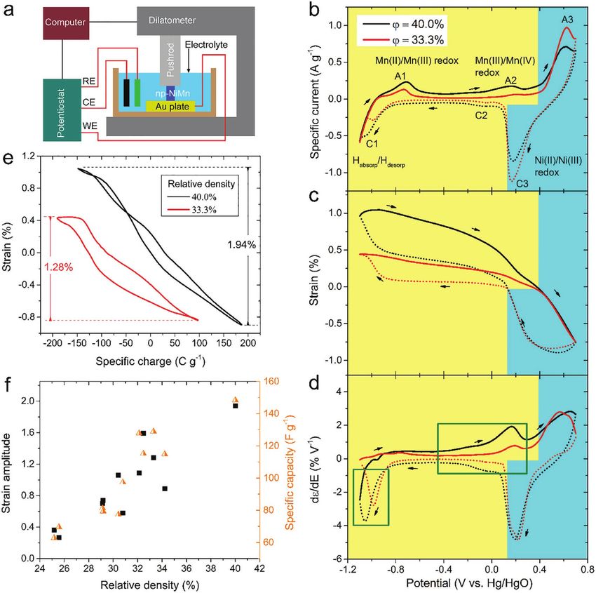
www.advancedsciencenews.com
                                                                                                                            www.advelectronicmat.de

Figure 3. SEM characterization of annealed nanoporous Ni–Mn metal. a) A bi-continuous porous structure obtained after annealing in a vacuum
(
www.advancedsciencenews.com
                                                                                                                                 www.advelectronicmat.de

Figure 4. Electrochemical actuation of as-dealloyed nanoporous Ni–Mn with different relative densities, ϕ. a) Illustration of an experimental setup for
in situ measurement. b) Cyclic voltammetry of nanoporous metals in 1 m NaOH electrolyte at 1 mV s−1 scan rate. c) Actuation strain as a function of
electrode potential. d) Strain-potential coefficient (dε/dE) as a function of potential. For a clear illustration, the coefficient of the anodic scan (solid
curve) is multiplied by −1. e) Reversible actuation strain as a function of specific charge. f) Actuation strain amplitude as a function of relative density
(left axis), and specific capacity as a function of relative density (right axis).

with different relative densities, the actuation contribution of                contraction. These volume changes have been reflected by the
Mn can be disclosed.                                                            increase and then decrease of the actuation strain, as shown
   Cyclic voltammetry (CV) of the two samples was conducted                     in Figure 4c. Ni oxidation happens around the anodic peak
in 1 m NaOH electrolyte at 1 mV s−1 scan rate. In Figure 4b,                    A1, that is, Ni → α-Ni(OH)2,[25a] which induces volume expan-
both samples are dominated by electrochemical signals of the                    sion and counteracts some part of the volume contraction
Ni component. Specifically, the cathode peak C1 and anodic                      induced by hydrogen desorption. In the middle of the CV, the
peak A1 are due to hydrogen absorption and then desorption                      flat current region corresponds to the electrochemical double-
into/from Ni,[25] which leads to volume expansion and then                      layer, which induces a linear change of the actuation strain,

Adv. Electron. Mater. 2021, 7, 2100381       2100381 (5 of 12)                 © 2021 The Authors. Advanced Electronic Materials published by Wiley-VCH GmbH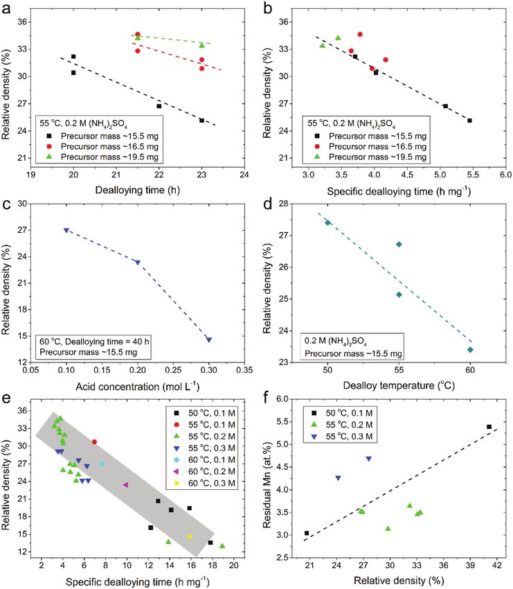
www.advancedsciencenews.com
www.advelectronicmat.de
as shown in the corresponding region in Figure 4c. During potentials in hierarchical structured nanoporous nickel.[16c] For
the positive scanning, α-Ni(OH)2 transforms to a more stable noble metals, Shi et al.[33] and Zhang et al.[34] reported actuation
phase of β-Ni(OH)2.[26] The anodic peak A3 and cathodic peak strains of 3.95% and 3.28%, respectively, in nanoporous Pd due
C3 are attributed to the redox reaction of β-Ni(OH)2 + OH− ↔ to the H absorption/desorption processes and experienced H2
β-NiOOH + H2O + e−. The lattice mismatching between bubbling.
β-NiOOH and β-Ni(OH)2 results in volume contraction in the Following Figure 4b–e, a series of nanoporous Ni–Mn sam-
forward direction and expansion in the backward direction.[27] ples were tested by CV and the corresponding strain ampli-
This redox reaction induces similar strain amplitude for both tudes were measured by dilatometry. Figure 4f (left axis) shows
samples, as shown in the cyan region of Figure 4c. Because of a trend that the strain amplitude increases almost linearly
the above series of reactions, both samples experience a contin- with the relative density. As residual Mn is the reason for the
uous volume contraction during the positive scanning, which is increase of relative density, it indicates Mn plays a significant
recovered during the negative scanning (Figure 4c). role to enhance the actuation strain amplitude. Figure 4f (right
The electrochemical contribution of Mn is reflected by the axis) plots the specific capacity of those nanoporous metals as
difference between ϕ = 40.0% (black) and ϕ = 33.3% (red) in a function of relative density, where the specific capacity was
Figure 4b. Within an alkaline electrolyte, Mn(OH)2 is formed obtained from negative scanning of the CV. It shows the spe-
on the Mn surface before testing, or at an electrode potential cific capacity is linearly proportional to the relative density, too.
(−1.66V vs Hg/HgO)[28] that is below the present CV range. Bear in mind the charge-induced strain effect, this explains
During positive scanning, Mn(OH)2 is first oxidized to a tran- why the actuation strain amplitude increases with the relative
sitional state:[21b,29] Mn(OH)2 + OH− → MnOOH + H2O + e−, density in Figure 4f (left axis).
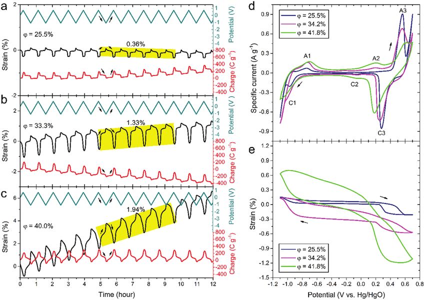
and then further oxidized to MnO2 at the anodic peak A2:[29,30] In Figure 5a–c, electrode potential cyclically scans for 12
MnOOH + OH− → MnO2 + H2O + e−. Both reactions are accom- successive cycles at a scan rate of 1 mV s−1 within the same
panied by H+ deintercalation from Mn compounds which lead potential region and electrolyte. Both actuation strain and the
to volume contraction.[31] Due to the extra Mn, a much steeper corresponding specific charge vary accordingly with potential.
strain reduction is found for ϕ = 40.0% (black) compared with As noticed by the arrows, during positive potential scanning,
ϕ = 33.3% (red) in Figure 4c. During negative scanning, MnO2 the specific charge increases and the actuation strain decreases;
is reduced back to MnOOH at the cathode peak C2, and then vice versa for the negative potential scanning. These trends are
continuously reduced to Mn(OH)2 through a wide region from consistent with Figure 4b–d. With relative density increasing
C2 toward the negative potentials.[30a] At the end of the negative from 25.5% to 33.3% and 40.0%, the strain amplitude increases
scanning (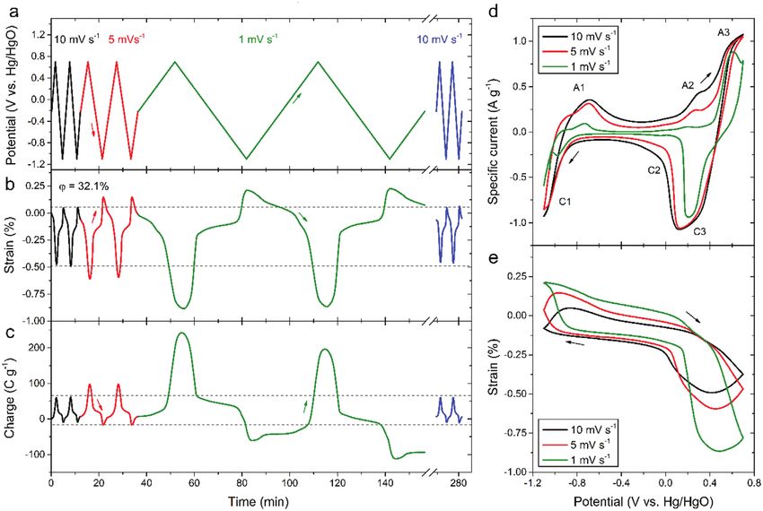
www.advancedsciencenews.com
                                                                                                                               www.advelectronicmat.de

Figure 5. Dependence of electrochemical actuation on relative densities of nanoporous Ni–Mn. a–c) Actuation strain (left axis), specific charge (right
axis), and electrode potential (right axis) as a function of actuation time. 12 cycles were scanned in the range of [−1.1, 0.7] V versus Hg/HgO at a rate
of 1 mV s−1 in 1 m NaOH. d) Specific current as a function of electrode potential and e) the corresponding actuation strain as a function of electrode
potential.

   For a sample with ϕ = 32.1%, continuous actuation testing                  2.3. Relative Density of Nanoporous Ni–Mn
was conducted for ≈5 h without observation of strain shift
(Figure S1, Supporting Information). Figure 6a shows that the                 Because actuation strain and specific capacity were measured
scan rate decreases from 10 to 5 mV s−1, and to 1 mV s−1, and                 by separate instruments, that is, a dilatometer and a potentio-
two cycles are scanned at each scan rate. Accordingly, the actua-             stat, the consistency between them with respect to relative den-
tion strain amplitude increases from 0.53% to 0.74%, and to                   sity undoubtedly proves that the relative density is a key tuning
1.08% (Figure 6b) and the specific charge amplitude increases                 factor to enhance the electrochemical actuation. It is important
from 71 to 113 C g−1, and to 280 C g−1 (Figure 6c). After two                 to have good control of the relative density for actuator design.
hours of resting, the strain amplitude is recovered to be 0.52%               Therefore, the dependence of relative density on various deal-
at 10 mV s−1, which shows a stable and repeatable actuation,                  loying conditions was investigated.
as noticed by the dashed lines in Figure 6b,c for curves at                      After a series of dealloying experiments, four dealloying con-
10 mV s−1.                                                                    ditions were found to be the major influencing factors on rela-
   From cyclic voltammograms in Figure 6d, the oxidation peak                 tive density, that is, dealloying time, acid concentration, deal-
that close to the positive potential end gradually disappears                 loying temperature, and precursor mass. Because the Ni30Mn70
with the scan rate increasing from 1 to 10 mV s−1, because the                precursors were cut into a self-similar geometry of ≈1:1:2
sluggish ion transport within the nanoporous structure limits                 dimensional-ratio, the influence of precursors’ geometry was
the charge-transfer reaction rate of the redox couples, that is,              not considered here.
Ni(OH)2/NiOOH and Mn(OH)2/MnOOH/MnO2. Accordingly,                               When the acid concentration, dealloying temperature, and
the actuation strain amplitude decreases most obviously at the                precursor mass are maintained the same, Figure 7a shows that
corresponding potential range between 0.2 and 0.7 V versus                    relative density decreases almost linearly with dealloying time.
Hg/HgO.                                                                       With the precursor mass increasing, the decreasing gradient

Adv. Electron. Mater. 2021, 7, 2100381       2100381 (7 of 12)               © 2021 The Authors. Advanced Electronic Materials published by Wiley-VCH GmbH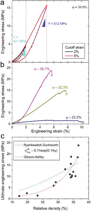
www.advancedsciencenews.com
www.advelectronicmat.de
Figure 6. Dependence of electrochemical actuation on potential scan rates. a–c) Electrode potential, actuation strain, and specific charge as a function
of actuation time, respectively. The potential scan rate increases from 10, to 5, to 1 mV s−1, and after 2 h of resting, to 10 mV s−1 again. Two cycles are
scanned at each scan rate. d) Specific current as a function of electrode potential and e) the corresponding actuation strain as a function of electrode
potential. The nanoporous Ni–Mn has a relative density of 32.1%.
becomes less steep, because larger samples need more time to In Figure S2, Supporting Information, nitrogen adsorp-
be dealloyed to the same extent. As it is not easy to cut mm- tion/desorption isotherms analyzed by the density functional
sized precursors with identical masses, we use a specific deal- theory method reveals that a nanoporous metal with a higher
loying time (i.e., time divided by precursor mass) to eliminate relative density (ϕ = 41.8%) has a smaller specific surface area
the influence of mass. Indeed, Figure 7b shows precessors (17.5 m2 g−1), while a sample with a lower relative density (ϕ =
with different masses fall into the same linear relationship 32.2%) has a larger specific surface area (27.6 m2 g−1). Thus,
between relative density and specific dealloying time. Figure 7c the specific surface area of nanoporous metal reduces with
shows that relative density decreases with acid concentration residual Mn increasing. It is worth to note that the exact sur-
increasing when the other three influencing factors are main- face area evaluated by different methods may be different, such
tained the same, and Figure 7d shows that relative density as double-layer capacitance method[36] and nitrogen adsorption/
decreases with dealloying temperature. Figure 7e summarizes desorption method,[37] but there it is the relative values that
the dependence of relative density on the specific dealloying matters for the present discussion. From the pore size distribu-
time at various acid concentrations and temperatures. Remark- tion shown in Figure S2c, Supporting Information, over 50%
ably, all the 31 dealloyed samples fall into a simple linear region, of the specific surface area is contributed from pores with radii
as noticed by the grey region in Figure 7e. Therefore, to obtain less than 20 Å (dashed line).
a nanoporous metal with a certain relative density, even though A smaller specific surface area limits the double-layer
the dealloying conditions may be different, the required deal- capacity at the electrode/electrolyte interface, which can lead
loying time can be predicted from Figure 7e. Figure 7f shows to the reduction of actuation strain, such as the nanoporous
that, from SEM-EDX element analysis of the dealloyed sam- noble metal actuators or nanoporous carbon-based actuators,
ples, the residual Mn content almost linearly increases with the in which the actuation strain was positively proportional to the
relative density, where residual MnMn at.%/ (Ni at.% +Mn specific surface area.[6] It is the case when the actuation mecha-
at.%). This relationship correlates the actuation enhancement nism is maintained the same, and the specific surface area
because of relative density (Figure 4f) to the residual Mn con- becomes the major way to enhance actuation. However, it is
tent (Figure 7f). not the case when the actuation mechanism changes due to the
Adv. Electron. Mater. 2021, 7, 2100381 2100381 (8 of 12) © 2021 The Authors. Advanced Electronic Materials published by Wiley-VCH GmbHwww.advancedsciencenews.com
www.advelectronicmat.de
Figure 7. Dependence of relative density on dealloying conditions of as-dealloyed nanoporous metals. a) Relative density versus dealloying time for
precursors with different masses. b) Relative density versus specific dealloying time (i.e., normalized dealloying time) corresponding to (a). c) Relative
density versus acid concentration of the dealloying solution (NH4)2SO4. d) Relative density versus dealloying temperature. e) A statistic plot of relative
density as a function of specific dealloying time, at different temperatures and acid concentrations. f) Mn content in the nanoporous Ni–Mn metal as
a function of relative density.
Adv. Electron. Mater. 2021, 7, 2100381 2100381 (9 of 12) © 2021 The Authors. Advanced Electronic Materials published by Wiley-VCH GmbHwww.advancedsciencenews.com
www.advelectronicmat.de
adding of a secondary actuation material. A higher relative den-
sity corresponds to a lower specific surface area (Figure S2b,
Supporting Information), while the higher relative density
enhances the actuation strain rather than reduces the strain
(Figures 4f, 5a–c). It is because the residual Mn introduces a
more effective actuation mechanism than that of the host Ni
(Figures 4b, 5d). Therefore, the secondary actuation metal (Mn)
within the primary actuation network (Ni) is a solution to avoid
the high specific surface area and low relative density in nano-
porous metals, while achieving the enhanced actuation strain.
As demonstrated in the following section, low relative density
is detrimental to the mechanical strength of the nanoporous
metals which is another factor for high-performing actuators.
2.4. Mechanical Characterization of Nanoporous Ni–Mn
Besides actuation enhancement, higher relative density brings
another benefit for actuator applications, which is the increase
of mechanical strength. Uniaxial compression tests of bulk
as-dealloyed nanoporous Ni–Mn were conducted. Figure 8a
shows the engineering stress versus strain relationship. The
effective Young’s modulus increases (from 421 to 512 MPa)
with the unloading strain increasing (from 2% to 5%). This
trend is due to the densification of the nanoporous structure
under compression.[38] Figure 8b shows the achievable max-
imum engineering strain increases with the relative density
decreasing, but the ultimate engineering strength decreases.
The achievable strains are much larger than the charge-induced
strain (1.94% in Figure 4b), which means the samples have
enough mechanical strength to support the actuation.
Figure 8c shows that the ultimate engineering strength σ eng ulti
increases with the relative density and follows an exponential
relationship, σ engulti
= 0.11exp(0.14ϕ ), where ϕ is relative den-
sity. This relationship complies with Ryshkewitch–Duchworth
model that was obtained from compression tests of porous
ceramics.[39] It is different from the well-known Gibson–Ashby
formula σ eng
ulti
= cσ sϕ n , where the best fitting parameters are c =
0.27, n = 2 and σs = 450 MPa (the strength of the solid phase).
It is possibly because Gibson–Ashby model was derived from
idealized porous structures,[18a] which is different from deal-
loyed porous structures that have a wide range of pore size, dis-
ordered arrangement, and dangling ligaments—free end liga-
ments that do not carry loads.[18b,40] In brief, the extra Mn inside
nanoporous Ni–Mn metal not only linearly elevates the actua-
tion strain amplitude (Figure 4f and 7f) but also exponentially
enhances the ultimate engineering strength of the actuator
(Figure 8c).
3. Conclusion
Figure 8. Mechanical characterization of as-dealloyed nanoporous Ni–
This article reports a way to simultaneously enhance the actua- Mn. a) Engineering stress versus engineering strain for a sample with
tion strain and mechanical strength of metallic-based electro- relative density 30.9%. It is measured by a uniaxial compression test at a
10−4 s−1 strain rate. Unloading starts at 2% and 5% cutoff-strain, respec-
chemical actuators, which overcomes the critical challenge that tively. b) Engineering stress versus engineering strain for samples with
hinders the competitive actuation performance. A secondary different relative densities. c) Ultimate engineering strength as a function
actuation metal Mn is homogeneously distributed on a 3D of relative density. Symbols are experimental results and dash lines are
interconnected Ni network that is synthesized by chemical model fittings.
dealloying. The actuation amplitude increases with extra Mn
Adv. Electron. Mater. 2021, 7, 2100381 2100381 (10 of 12) © 2021 The Authors. Advanced Electronic Materials published by Wiley-VCH GmbHwww.advancedsciencenews.com
www.advelectronicmat.de
because of a two-electron-transfer redox of Mn(OH)2/MnOOH/ support of the DFG via SFB “M3” subproject B2. The authors thank Prof.
MnO2, which induces volume expansion/contraction via H+ Jörg Weissmüllar for the discussions.
intercalation/deintercalation. This actuation mechanism is Open access funding enabled and organized by Projekt DEAL.
more effective than the one-electron-transfer redox of Ni(OH)2/
NiOOH in the Ni host network. As a result, a strain ampli-
tude of 1.94% is obtained, which is a recorded high value for Conflict of Interest
metallic-based actuators. At the same time, due to the extra Mn The authors declare no conflict of interest.
content, the mechanical strength of the actuator is enhanced
exponentially by the increase of relative density, complying with
the Ryshkewitch–Duchworth model. Therefore, this research
may find a way to fabricate high actuation performance and Data Availability Statement
mechanically robust metallic actuators. The data that support the findings of this study are available from the
corresponding author upon reasonable request.
4. Experimental Section
Keywords
Synthesis of Nanoporous Ni–Mn Alloy: The synthesis method was
reported by the authors before.[16b] Ni30Mn70 alloy ingot was cast by an charge-induced strain, dealloying, metallic actuators, nanoporous
induction cold crucible furnace (Arcast) in Ar atmosphere by using Ni metals, pesudocapacity
and Mn metals (>99.99% pure, ChemPUR). The ingot was cut into disks
(≈16 mm in diameter and ≈2.5 mm in thickness) by a mechanical saw Received: April 13, 2021
and annealed at 900 °C for 24 h under vacuum and then quenched in Published online: May 13, 2021
water. During heat treatment, the heating rate was not controlled, but the
quenching rate was from 900 °C to room temperature within seconds.
The disks were mechanically polished and cut into cuboids (≈1 × 1 ×
2 mm3) by diamond wire saw. Bulk nanoporous Ni–Mn was synthesized [1] a) R. H. Baughman, C. Cui, A. A. Zakhidov, Z. Lqbal, J. N. Barisci,
by chemical dealloying in 0.05, 0.1, 0.2, and 0.3 m (NH4)2SO4 solutions at G. M. Spinks, G. G. Wallace, A. Mazzoldi, D. D. Rossi, A. G. Rinzler,
constant temperatures of 70, 50, 55, and 55 °C, respectively. The influence O. Jaschinski, S. Roth, M. Kertesz, Science 1999, 284, 1340;
of synthesis conditions on the dealloyed sample is shown in Figure 7. b) M. Acerce, E. K. Akdoğan, M. Chhowalla, Nature 2017, 549,
Materials Characterization: The morphology of nanoporous structures 370; c) S. Umrao, R. Tabassian, J. Kim, V. H. Nguyen, Q. Zhou,
was observed by STEM carried out in an FEI Talos F200X and SEM S. Nam, I.-K. Oh, Sci. Robot. 2019, 4, eaaw7797; d) J. Weissmüller,
carried out in a Zeiss Supra 55 VP FEG-SEM combined with EDX. R. N. Viswanath, D. Kramer, P. Zimmer, R. Würschum, H. Gleiter,
Macroscopic photos of the bulk nanoporous metals were captured by Science 2003, 300, 312.
optical microscopy (Leica M205C, Germany). Uniaxial compression [2] a) Q. M. Zhang, H. F. Li, M. Poh, F. Xia, Z. Y. Cheng, H. S. Xu,
tests were conducted on a universal testing machine (Zwick 1474) at a C. Huang, Nature 2002, 419, 284; b) Q. Zhang, V. Bharti, X. Zhao,
constant engineering strain rate of 10−4 s−1 with a pre-load of 0.3 N at the Science 1998, 280, 2101; c) I. Kim, H. Roh, J. Yu, N. Jayababu, D. Kim,
beginning of the measurement for close contact between sample and
ACS Energy Lett. 2020, 5, 1577; d) R. H. Baughman, Science 2003,
pushrod. The effective (macroscope) Young’s modulus was determined
300, 268; e) C. Lu, Y. Yang, J. Wang, R. Fu, X. Zhao, L. Zhao, Y. Ming,
during unloading at different deformation stages. The specific surface
Y. Hu, H. Lin, X. Tao, Y. Li, W. Chen, Nat. Commun. 2018, 9, 752.
area of the nanoporous samples was measured by nitrogen adsorption/
desorption processes at 77 K using a Quantachrome Autosorb surface [3] J. Mu, M. Jung de Andrade, S. Fang, X. Wang, E. Gao, N. Li,
analyzer and analyzed by density functional theory method. S. H. Kim, H. Wang, C. Hou, Q. Zhang, M. Zhu, D. Qian, H. Lu,
Electrochemical Actuation Measurement: The linear actuation strain D. Kongahage, S. Talebian, J. Foroughi, G. Spinks, H. Kim,
of bulk nanoporous metal was measured in situ in an electrochemical T. H. Ware, H. J. Sim, D. Y. Lee, Y. Jang, S. J. Kim, R. H. Baughman,
cell, combined with a computer-controlled dilatometer (Linseis, L75 Science 2019, 365, 150.
vertical dilatometer) and a potentiostat (Autolab, PGSTAT302N). A glass [4] E. W. H. Jager, O. Inganas, I. Lundström, Science 2000, 288, 2335.
push rod which was connected with the displacement sensor of the [5] K. W. Kwan, S. J. Li, N. Y. Hau, W.-D. Li, S. P. Feng, A. H. W. Ngan,
dilatometer had a constant compressive pressure (≈0.2 MPa) on the top Sci. Robot. 2018, 3, eaat4051.
surface of the sample in order to maintain close contact between the [6] H. J. Jin, X. L. Wang, S. Parida, K. Wang, M. Seo, J. Weissmüller,
pushrod and the sample. The electrochemical cell was filled with 1 m Nano Lett. 2010, 10, 187.
NaOH electrolyte with the nanoporous metal as a WE, a piece of carbon [7] a) C. Cheng, J. Weissmüller, A. H. W. Ngan, Adv. Mater. 2016, 28,
clothes as a counter electrode, and a commercial Hg/HgO reference 5315; b) D. Kramer, R. N. Viswanath, J. Weissmüller, Nano Lett.
electrode (Sensortechnik Meinsberg, Germany). 2004, 4, 793.
[8] a) Z. Jiao, C. Zhang, W. Wang, M. Pan, H. Yang, J. Zou, Adv. Sci.
2019, 6, 1901371; b) H. Chu, X. Hu, Z. Wang, J. Mu, N. Li, X. Zhou,
Supporting Information S. Fang, C. S. Haines, J. W. Park, S. Qin, N. Yuan, J. Xu, S. Tawfick,
H. Kim, P. Conlin, M. Cho, K. Cho, J. Oh, S. Nielsen, K. A. Alberto,
Supporting Information is available from the Wiley Online Library or J. M. Razal, J. Foroughi, G. M. Spinks, S. J. Kim, J. Ding, J. Leng,
from the author. R. H. Baughman, Science 2021, 371, 494.
[9] a) M. Hughes, G. M. Spinks, Adv. Mater. 2005, 17, 443; b) T. Zheng,
P. Pour Shahid Saeed Abadi, J. Seo, B.-H. Cha, B. Miccoli, Y.-C. Li,
K. Park, S. Park, S.-J. Choi, R. Bayaniahangar, D. Zhang, S.-H. Lee,
Acknowledgements C.-K. Lee, A. Khademhosseini, S. R. Shin, ACS Appl. Mater. Inter-
C.C. thank for the Humboldt Research Fellowship from Alexander von faces 2019, 11, 20615; c) G. W. Rogers, J. Z. Liu, J. Am. Chem. Soc.
Humboldt Foundation, Germany. The authors thank for the financial 2011, 133, 10858.
Adv. Electron. Mater. 2021, 7, 2100381 2100381 (11 of 12) © 2021 The Authors. Advanced Electronic Materials published by Wiley-VCH GmbHwww.advancedsciencenews.com
www.advelectronicmat.de
[10] a) T. H. T. Fook, J. H. Jeon, P. S. Lee, Adv. Mater. Technol. 2020, 5, [22] J. Weissmüller, K. Sieradzki, MRS Bull. 2018, 43, 14.
1900762; b) J. G. Martinez, T. F. Otero, E. W. H. Jager, Langmuir [23] D. B. Williams, C. B. Carter, Transmission Electron Microscopy, Part 1:
2014, 30, 3894. Basics, Springer, New York 2009.
[11] a) Y. Yan, T. Santaniello, L. G. Bettini, C. Minnai, A. Bellacicca, [24] A. Biswal, B. C. Tripathy, K. Sanjay, T. Subbaiah, M. Minakshi, RSC
R. Porotti, I. Denti, G. Faraone, M. Merlini, C. Lenardi, P. Milani, Adv. 2015, 5, 58255.
Adv. Mater. 2017, 29, 1606109; b) Q. He, Z. Liu, G. Yin, Y. Yue, [25] a) D. S. Hall, C. Bock, B. R. MacDougall, J. Electrochem. Soc. 2013,
M. Yu, H. Li, K. Ji, X. Xu, Z. Dai, M. Chen, Smart Mater. Struct. 2020, 160, F235; b) B. Baranowski, S. Majchrzak, T. B. Flanagan, J. Phys.
29, 045013; c) E. Griffiths, J. Wilmers, S. Bargmann, B. D. Reddy, F: Met. Phys. 1971, 1, 258; c) D. S. Hall, D. J. Lockwood, C. Bock,
J. Mech. Phys. Solids 2020, 137, 103848. B. R. MacDougall, Proc. R. Soc. A 2015, 471, 20140792.
[12] a) E. Detsi, S. H. Tolbert, S. Punzhin, J. T. M. De Hosson, J. Mater. [26] S. L. Yau, F. R. F. Fan, T. P. Moffat, A. J. Bard, J. Phys. Chem. 1994,
Sci. 2016, 51, 615; b) E. Detsi, P. Onck, J. T. M. De Hosson, ACS 98, 5493.
Nano 2013, 7, 4299; c) T. Juarez, J. Biener, J. Weissmüller, [27] a) D. Singh, J. Electrochem. Soc. 1998, 145, 116; b) M. B. J. G. Freitas,
A. M. Hodge, Adv. Eng. Mater. 2017, 19, 1700389. J. Power Sources 2001, 93, 163; c) M. S. Kim, K. B. Kim, J. Electro-
[13] a) Y. H. Xue, J. Markmann, H. L. Duan, J. Weissmüller, P. Huber, chem. Soc. 1998, 145, 507; d) M. S. Kim, T. S. Hwang, K. B. Kim,
Nat. Commun. 2014, 5, 4237; b) H. J. Jin, J. Weissmüller, Science J. Electrochem. Soc. 1997, 144, 1537.
2011, 332, 1179; c) Q. Bai, C. Zhang, F. Tan, F. Wu, Z. Zhang, Electro- [28] a) M. Pourbaix, Atlas of Electrochemical Equilibria in Aqueous Solu-
chem. Commun. 2021, 124, 106940; d) R. N. Viswanath, D. Kramer, tions, Pergamon Press Ltd. , London 1966; b) A. J. Bard, R. Parsons,
J. Weissmüller, Electrochim. Acta 2008, 53, 2757. J. Jordan, Standard Potentials in Aqueous Solutions, Marcel Dekker,
[14] Z. Qi, J. Weissmüller, ACS Nano 2013, 7, 5948. Inc., New York 1985.
[15] X. L. Ye, H. J. Jin, Appl. Phys. Lett. 2013, 103, 201912. [29] D. K. Cha, J. Electrochem. Soc. 1997, 144, 2573.
[16] a) M. Hakamada, S. Matsumura, M. Mabuchi, Mater. Lett. 2012, [30] a) A. Kozawa, J. F. Yeager, J. Electrochem. Soc. 1965, 112, 959;
70, 132; b) C. Cheng, L. Lührs, T. Krekeler, M. Ritter, J. Weissmüller, b) J. Haines, J. M. Léger, S. Hoyau, J. Phys. Chem. Solids 1995, 56,
Nano Lett. 2017, 17, 4774; c) Q. Bai, Y. Wang, J. Zhang, Y. Ding, 965; c) W. M. Dose, J. Lehr, S. W. Donne, Mater. Res. Bull. 2012, 47,
Z. Peng, Z. Zhang, J. Mater. Chem. C 2016, 4, 45; d) C. Cheng, 1827.
A. H. W. Ngan, ACS Nano 2015, 9, 3984. [31] a) D. A. Kitchaev, S. T. Dacek, W. H. Sun, G. Ceder, J. Am. Chem.
[17] B. E. Conway, Electrochemical Supercapacitors: Scientific Fundamen- Soc. 2017, 139, 2672; b) C. Poinsignon, M. Amarilla, F. Tedjar,
tals and Technological Applications, Springer Science & Business J. Mater. Chem. 1993, 3, 1227.
Media, New York 2013. [32] M. Krukowski, B. Baranowski, J. Less-Common Met. 1976, 49,
[18] a) L. J. Gibson, M. F. Ashby, Cellular Solids: Structure and Proper- 385.
ties, Cambridge University Press, Cambridge 1997; b) Y.-H. Xiang, [33] S. Shi, J. Markmann, J. Weissmüller, Philos. Mag 2017, 97, 1571.
L.-Z. Liu, J.-C. Shao, H.-J. Jin, Acta. Mater. 2020, 186, 105. [34] D. S. Hall, Ph.D. Thesis, University of Ottawa, Canada 2014.
[19] J. Erlebacher, M. J. Aziz, A. Karma, N. Dimitrov, K. Sieradzki, Nature [35] C. Cheng, P. S. Grant, L. Lührs, Adv. Electron. Mater. 2020, 6,
2001, 410, 450. 1900364.
[20] a) M. Toupin, T. Brousse, D. Bélanger, Chem. Mater. 2004, 16, 3184; [36] C. Lakshmanan, R. N. Viswanath, S. R. Polaki, R. Rajaraman, AIP
b) J. L. Kang, A. Hirata, H. J. Qiu, L. Y. Chen, X. B. Ge, T. Fujita, Conf. Proc. 2015, 1665, 140033.
M. W. Chen, Adv. Mater. 2014, 26, 269; c) X. Lang, A. Hirata, [37] H. J. Qiu, Y. Ito, M. W. Chen, Scr. Mater. 2014, 89, 69.
T. Fujita, M. Chen, Nat. Nanotechnol. 2011, 6, 232. [38] N. Mameka, J. Markmann, H. J. Jin, J. Weissmüller, Acta Mater.
[21] a) L. Liu, L. Su, Y. Lu, Q. Zhang, L. Zhang, S. Lei, S. Shi, M. D. Levi, 2014, 76, 272.
X. Yan, Adv. Funct. Mater. 2019, 29, 1806778; b) Z. M. Chan, [39] a) E. Ryshkewitch, J. Am. Ceram. Soc. 1953, 36, 65; b) S. C. Carniglia,
D. A. Kitchaev, J. N. Weker, C. Schnedermann, K. Lim, G. Ceder, J. Am. Ceram. Soc. 1972, 55, 610.
W. Tumas, M. F. Toney, D. G. Nocera, Proc. Natl. Acad. Sci. USA [40] N. Huber, R. N. Viswanath, N. Mameka, J. Markmann,
2018, 115, E5261. J. Weissmüller, Acta Mater. 2014, 67, 252.
Adv. Electron. Mater. 2021, 7, 2100381 2100381 (12 of 12) © 2021 The Authors. Advanced Electronic Materials published by Wiley-VCH GmbHYou can also read