Vertically Aligned and Interconnected Graphite and Graphene Oxide Networks Leading to Enhanced Thermal Conductivity of Polymer Composites - MDPI
←
→
Page content transcription
If your browser does not render page correctly, please read the page content below
polymers
Article
Vertically Aligned and Interconnected Graphite and
Graphene Oxide Networks Leading to Enhanced
Thermal Conductivity of Polymer Composites
Ziming Wang *, Yiyang Cao, Decai Pan and Sen Hu
 College of Aerospace Engineering, Chongqing University, Chongqing 400044, China;
 20176262@cqu.edu.cn (Y.C.); peter_spread@163.com (D.P.); 20176238@cqu.edu.cn (S.H.)
 * Correspondence: wangzm@cqu.edu.cn; Tel.: +86-17772481963

 Received: 28 March 2020; Accepted: 6 May 2020; Published: 14 May 2020

 Abstract: Natural graphite flakes possess high theoretical thermal conductivity and can notably
 enhance the thermal conductive property of polymeric composites. Currently, because of weak
 interaction between graphite flakes, it is hard to construct a three-dimensional graphite network to
 achieve efficient heat transfer channels. In this study, vertically aligned and interconnected graphite
 skeletons were prepared with graphene oxide serving as bridge and support via freeze-casting
 method. Three freezing temperatures were utilized, and the resulting graphite and graphene oxide
 network was filled in a polymeric matrix. Benefiting from the ultralow freezing temperature of
 −196 ◦ C, the network and its composite occupied a more uniform and denser structure, which lead to
 enhanced thermal conductivity (2.15 W m−1 K−1 ) with high enhancement efficiency and prominent
 mechanical properties. It can be significantly attributed to the well oriented graphite and graphene
 oxide bridges between graphite flakes. This simple and effective strategy may bring opportunities to
 develop high-performance thermal interface materials with great potential.

 Keywords: polymer–matrix composite; graphene; thermal properties; mechanical testing

1. Introduction
      With the rapid development of electronic devices, thermal dissipation has become a critical
necessity for its reliability, lifetime, and high speed [1–3]. To achieve an efficient management of
thermal dissipation, thermal interface materials (TIM) are widely used in high-power electronics [4–6],
especially in next-generation electronic devices such as the smart phone, high-performance computer,
and light-emitting diodes. Polymer-based composites with high thermal conductivity play an irreplaceable
role as a typical candidate of TIM [7,8]. That is not only because of their remarkable performance
in thermal dissipation of electronics, but also their light-weight, flexibility, and easy processing
features [9]. Usually, the inorganic thermal conductive fillers are uniformly dispersed in polymer
matrix to obtain the high thermal conductivity, including metals [10–12], α-alumina (α-Al2 O3 ) [13–15],
hexagonal boron nitride (h-BN) [16–19], nanoclays [20], carbon nanotubes (CNTs) [21–24], and their
hybrid mixtures [25,26]. However, with separated fillers, it is hard to introduce high thermal conductivity
to the composites due to the lack of efficient heat transfer pathways and high interfacial thermal
resistance between the fillers and polymer matrix [27]. Therefore, presently, some special strategies are
also continuously developed, with constructing three-dimensional (3D) structures as one of the most
effective methods.
      Natural graphite flakes, as platelet-like thermally conductive fillers, have attracted lots of attention
because of their high aspect ratio and theoretical thermal conductivity (~129 W m−1 K−1 ) [28]. It has
been demonstrated that graphite can notably enhance the thermal conductive property of composites

Polymers 2020, 12, 1121; doi:10.3390/polym12051121                             www.mdpi.com/journal/polymers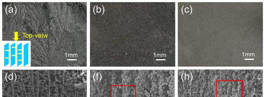
Polymers 2020, 12, 1121                                                                               2 of 15

when they are added into the polymeric matrices [5,29,30]. Unlike special carbon materials such as
graphene [31–34], carbon nanotubes [35,36], as well as fullerene [37], which have complex fabricating
procedures, natural flake graphite is easily obtained. In addition, it is relatively simple to acquire high
loading for graphite in a polymeric matrix without agglomeration via the usual fabrication ways due to
its insensitivity to the van der Waals forces. Nevertheless, due to the intrinsic microstructure of graphite
flakes, the thermal conductivity is anisotropic, that is, there is much higher thermal conductivity along
the in-plane direction than along the through-plane direction [3]. Thus, the graphite flakes should be
oriented in the heat transfer direction to fully utilize their in-plane thermal conductivity, instead of
distributing them randomly.
      To build the oriented architecture of anisotropic fillers, such as platelets [38,39], wires and
fibers [40,41], inside the polymer matrix, many strategies have been adopted in recent years. For example,
the vacuum filtration method was skillfully developed and utilized to achieve the oriented structures
of thermal conductive fillers [26,42]. This method always shows notable availability for fabricating
the paper-like composites [43] and obtaining high value of thermal conductivity in the horizontal
direction. However, in many cases, prominent thermal transfer along the vertical direction is more
desirable for realizing the efficient heat removal of TIM. Magnetic alignment is an attractive approach
in this regard, in which fillers are aligned along the external magnetic field after coating magnetic
iron oxide nanoparticles around the surface of the fillers [44,45]. However, the incorporated iron
oxide limits the thermal conductivity of the composite fillers and increases the total mass. Meanwhile,
other approaches, including hot-pressing [18,46], injection molding [47–49], 3D printing [50,51],
and electrospinning [52], are also widely applied. The ice-templating self-assembly method, which can
construct well-aligned architecture along the ice-growth direction, has been regarded as one of the most
promising strategies [3,53,54]. Such method, however, requires the strong interaction between particles
or platelets. Due to the lack of functional groups on the surface of graphite flakes, the interactions
between them are so weak that the bridge and support should be well constructed.
      Graphene oxide (GO), as one of the oxygen-containing derivatives of graphene, has attracted
much attention because of its outstanding physical properties [55–58]. Meanwhile, there are superb
hydrogen bonding interactions resulting from the abundant oxygen-containing groups (e.g., hydroxyl,
carboxyl, and epoxide groups) on its basal planes and edges [59–61]. Recently, it has been clearly
demonstrated that GO can interconnect with each other and assemble into a stable and specific structure
by the ice-templating self-assembly method [1,54,62–64]. Thus, it presents significant potential for
serving as the bridge and support of graphite flakes and forming 3D graphite networks.
      Herein, the vertically aligned graphite and GO networks were successfully synthesized by
freeze-casting method with tuned temperatures. Graphite flakes were well oriented in the direction
with their high thermal conductivity, and GO connected graphite flakes, presenting effective bridge and
support actions. Furthermore, the thermal conductivity and mechanical properties were reasonably
evaluated and analyzed, especially the impacts of the extremely low freezing temperature.

2. Materials and Experiments

2.1. Materials
     Natural graphite flakes were provided by Sinopharm Chemical Reagent Co., Ltd., Shanghai,
China. Hydroxyl-terminated polybutadiene (HTPB, 99.8%) was supplied by Hongyuan Chemical
Industry & New Material Technology Co., Ltd., Shenzhen, China, and regarded as the prepolymer of
polyurethane (PU). Isophorone diisocyanate (IPDI, 99%) and triphenylbismuthine (TPB) were obtained
from Aladdin Co., Shanghai, China. Dibutyl phthalate (DBP, 99.5%) was provided by Xilong Scientific
Co., Ltd., Shantou, China.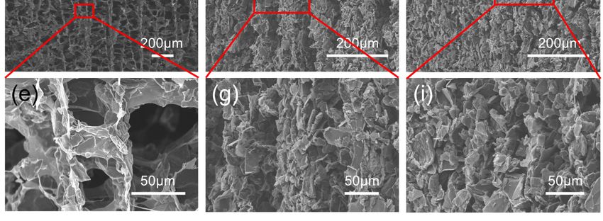
Natural graphite flakes were provided by Sinopharm Chemical Reagent Co., Ltd, Shanghai,
China. Hydroxyl-terminated polybutadiene (HTPB, 99.8%) was supplied by Hongyuan Chemical
Industry & New Material Technology Co., Ltd., Shenzhen, China, and regarded as the prepolymer of
polyurethane (PU). Isophorone diisocyanate (IPDI, 99%) and triphenylbismuthine (TPB) were
Polymers
obtained       12, 1121
            from
         2020,     Aladdin Co., Shanghai, China. Dibutyl phthalate (DBP, 99.5%) was provided by Xilong
                                                                                                 3 of 15
Scientific Co., Ltd., Shantou, China.
2.2. Preparation of 3D Graphite and Graphene Oxide Networks
2.2. Preparation of 3D Graphite and Graphene Oxide Networks
      Graphene oxide (GO) was fabricated from natural graphite flakes using modified Hummer’s
      Graphene oxide (GO) was fabricated from natural graphite flakes using modified Hummer’s
method [65], and the concentration of its water suspension was tuned to 6 mg/mL. Then, this water
method [65], and the concentration of its water suspension was tuned to 6 mg/mL. Then, this water
suspension (10 mL) was mixed with the natural graphite flakes (3 g) by rapid stir for 30 min.
suspension (10 mL) was mixed with the natural graphite flakes (3 g) by rapid stir for 30 min.
Subsequently, the obtained homogeneous mixture was poured into a mold, followed by adequate
Subsequently, the obtained homogeneous mixture was poured into a mold, followed by adequate
freezing with three different substrate temperatures (−5 ◦ C, −60 ◦ C, and −196 ◦ C). After freeze-drying
freezing with three different substrate temperatures (−5 °C, −60 °C, and −196 °C). After freeze-drying
at low temperature (−50 ◦ C) for 36 h, aligned 3D graphite and graphene oxide (3D-GP) aerogels were
at low temperature (−50 °C) for 36 h, aligned 3D graphite and graphene oxide (3D-GP) aerogels were
finally obtained.
finally obtained.
2.3. Preparation of Oriented 3D-GP/PU Network Composites
2.3. Preparation of Oriented 3D-GP/PU Network Composites
      HTPB prepolymer with 25 wt % DBP, 7.5 wt % IPDI, and an appropriate amount of TPB was
      HTPB prepolymer with 25 wt % DBP, 7.5 wt % IPDI, and an appropriate amount of TPB was
uniformly mixed through a mechanical agitator, and degassed in vacuum for 30 min at room temperature.
uniformly mixed through a mechanical agitator, and degassed in vacuum for 30 min at room
The mixture was then infused into 3D-GP skeletons, and after that, the compounds were put into
temperature. The mixture was then infused into 3D-GP skeletons, and after that, the compounds were
the vacuum oven at −25 Pa for 1 h. Because of the capillary action and low-pressure environment,
put into the vacuum oven at −25 Pa for 1 h. Because of the capillary action and low-pressure
the liquid HTPB prepolymer was successfully infiltrated into 3D-GP skeletons. Finally, the 3D-GP/PU
environment, the liquid HTPB prepolymer was successfully      infiltrated into 3D-GP skeletons. Finally,
composites were achieved after a curing process at 80 ◦ C for 48 h in an electrothermal blowing dryer.
the 3D-GP/PU composites were achieved after a curing process at 80 °C for 48 h in an electrothermal
The schematic illustration of the fabrication process is shown in Figure 1. For comparison, graphite
blowing dryer. The schematic illustration of the fabrication process is shown in Figure 1. For
flakes were directly mixed with HTPB prepolymer without 3D architecture, and the obtained composite
comparison, graphite flakes were directly mixed with HTPB prepolymer without 3D architecture,
was denoted as random GP/PU.
and the obtained composite was denoted as random GP/PU.

               Figure 1. Schematic diagram of the fabrication process of 3D-GP/PU composites.
               Figure 1. Schematic diagram of the fabrication process of 3D-GP/PU composites.
2.4. Characterization
      Fourier transform infrared (FTIR) spectra of the samples were recorded on an infrared
spectrophotometer (FT/IR-4100, Jasco, Tokyo, Japan). X-ray diffraction (XRD) patterns were obtained
on an X-ray diffractometer (D/max-2500/PC, Rigaku, Tokyo, Japan) with Cu Kα radiation (λ = 1.5418 Å)
at a scanning speed of 10◦ /min from 3◦ to 90◦ . Microstructure and morphology of the materials were
performed with field-emission scanning electron microscope (SEM, SU-8010, Hitachi, Tokyo, Japan) and
transmission electron microscope (TEM, JEM-2100F, JEOL, Tokyo, Japan) with an acceleration voltage
of 200 kV. The uniaxial tensile measurement was performed on Instron 5980 with the loading rate of
10 mm/min. The thermal decomposition was performed with thermogravimetric analysis (TGA Q600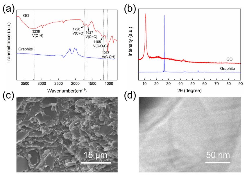
Polymers 2020, 12, 1121                                                                            4 of 15

SDT, TA Instrument, New Castle, DE, USA) at the nitrogen atmosphere from room temperature to
800 ◦ C at a heating rate of 10 ◦ C/min. Thermal conductivity (K) was calculated using

                                                   K=αρCp                                             (1)

where α is the thermal diffusivity coefficient obtained by LFA 467 HyperFlash instrument (Netzsch,
Bavaria, Germany), ρ is the density of the composites measured by XS105DU automatic density
analyzer (METTLER TOLEDO, Zurich, Switzerland), and Cp is the specific heat capacity measured by
DSC Q20 differential scanning calorimetry instrument (TA Instrument, New Castle, DE, USA).

3. Results and Discussion

3.1. Morphologic and Structural Characterization
     Figure 2a shows the FTIR spectra results of graphite and GO. It can be seen that several types of
functional groups were attached to the surface of GO without existing on graphite flakes. The presence
of absorption peaks at 1726 cm−1 (C=O stretching vibration), 1627 cm−1 (C=C stretching vibration),
1168 cm−1 (C−O−C stretching vibration), 1037 cm−1 (C−OH stretching vibration), and 3300–3000 cm−1
(O−H stretching vibration) in the spectrum of GO indicates that graphite was successfully oxidized
into GO by Hummer’s method. Because of the abundant functional groups on the surfaces and
the hydrogen-bonding interactions between them simultaneously, it was feasible to construct 3D
architecture via utilizing GO as the support of graphite flakes.
     XRD patterns of graphite and GO are presented in Figure 2b. Graphite exhibited a sharp peak
centered at 2θ = 26.4◦ , while in the pattern of GO, this peak could not be found and a characteristic
peak at 2θ = 11.0◦ appeared. Thus, GO shows a notably larger interlayer distance than that of graphite,
which clearly reveals the carbon layer exfoliation of graphite.
     In addition, the SEM image of graphite flakes is shown in Figure 2c, and we can see that they
exhibited a typical platelet-like shape with relatively high thickness. Meanwhile, the morphology of
GO sheets was characterized by TEM observation, as shown in Figure 2d. It is clear that GO sheets
presented much smaller thickness according to the excellent transmittance. The fold profile can also
be found in the TEM image, which is one of the characteristic morphology features of GO sheets.
This thin and flexible profile that is quite different from graphite makes GO sheets to be considered
as the reasonable bridge of graphite flakes. More than this, GO possesses the prominent mechanical
properties that bring the 3D structure more robustness and stability.
     Figure 3a–c present the top-view digital images of 3D-GP skeletons with freezing temperatures
of −5 ◦ C, −60 ◦ C, and −196 ◦ C, respectively, and for simplicity, the samples were named with the
freezing temperature. For example, 3D-GP5 means the skeleton with the freezing temperatures of
−5 ◦ C, and thus, the 3D-GP samples can be spelled into 3D-GP5, 3D-GP60, and 3D-GP196, respectively.
We can see that the top-view images show different surface features. With the decreasing of freezing
temperatures, the top surfaces of the skeletons were increasingly fine and smooth. That is because
the ice crystals would be smaller and smaller with the reducing of freezing temperature. According
to the previous study, the platelets of graphite and GO should be gradually driven to the gaps of ice
crystals during the freezing procedure [53]. Consequently, we can dominate the skeleton compactness
effectively by controlling the growth of ice crystals using temperature. Figure 3d–i show the side-view
SEM images of 3D-GP skeletons and can further verify this elaboration. It also can be seen that 3D-GP
skeletons were directionally organized, and graphite flakes were vertically assigned with GO serving
as bridge and support. Figure 3d shows the profile of 3D-GP5, which exhibited typical hierarchically
ordered and interconnected network of graphite and GO. The graphite flakes distributed along GO
support and established the quasi parallel composite layers (Figure 3e). The layers were hierarchically
arranged to construct a 3D structure. This phenomenon can also be found in 3D-GP60 and 3D-GP196
samples, which are shown in Figure 3f,h. However, due to the effect of ice crystal growing, the distances
of vertical layers reduced with decreasing temperature. That is to say, lower temperature could achieve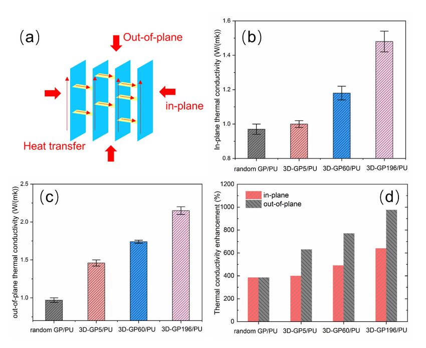
Polymers 2020, 12, 1121                                                                                                     5 of 15

denser structure. Moreover, most graphite flakes dispersed vertically, and the magnifications reveal
that theyPolymers
           were2020,
                  arrayed    orderly,
                     12, x FOR        resulting from the fabrication process.
                               PEER REVIEW                                              5 of 16

      Figure 2. (a) FTIR spectra of graphite and graphene oxide (GO). (b) XRD patterns of graphite and GO.
                Figure
          Polymers       2. (a)
                   2020, 12,    FTIR
                             x FOR   spectra
                                   PEER      of graphite and graphene oxide (GO). (b) XRD patterns of graphite and GO.
                                        REVIEW                                                                      6 of 16
      (c) SEM (c)
                image     of graphite flakes. (d) TEM image of GO.
                    SEM image of graphite flakes. (d) TEM image of GO.

               Figure 3a–c present the top-view digital images of 3D-GP skeletons with freezing temperatures
          of −5 °C, −60 °C, and −196 °C, respectively, and for simplicity, the samples were named with the
          freezing temperature. For example, 3D-GP5 means the skeleton with the freezing temperatures of −5
          °C, and thus, the 3D-GP samples can be spelled into 3D-GP5, 3D-GP60, and 3D-GP196, respectively.
          We can see that the top-view images show different surface features. With the decreasing of freezing
          temperatures, the top surfaces of the skeletons were increasingly fine and smooth. That is because
          the ice crystals would be smaller and smaller with the reducing of freezing temperature. According
          to the previous study, the platelets of graphite and GO should be gradually driven to the gaps of ice
          crystals during the freezing procedure [53]. Consequently, we can dominate the skeleton
          compactness effectively by controlling the growth of ice crystals using temperature. Figure 3d–i show
          the side-view SEM images of 3D-GP skeletons and can further verify this elaboration. It also can be
          seen that 3D-GP skeletons were directionally organized, and graphite flakes were vertically assigned
          with GO serving as bridge and support. Figure 3d shows the profile of 3D-GP5, which exhibited
          typical hierarchically ordered and interconnected network of graphite and GO. The graphite flakes
          distributed along GO support and established the quasi parallel composite layers (Figure 3e). The
          layers were hierarchically arranged to construct a 3D structure. This phenomenon can also be found
          in 3D-GP60 and 3D-GP196 samples, which are shown in Figure 3f,h. However, due to the effect of ice
          crystal growing, the distances of vertical layers reduced with decreasing temperature. That is to say,
          lower temperature could achieve denser structure. Moreover, most graphite flakes dispersed
          vertically, and the magnifications reveal that they were arrayed orderly, resulting from the
          fabrication process.

      Figure 3. (a–c) Top-view digital images of 3D-GP skeletons with freezing temperatures of −5 ◦ C,
              Figure 3. (a–c) Top-view digital images of 3D-GP skeletons with freezing temperatures of −5 °C, −60
      −60 ◦ C, and −196 ◦ C, respectively. Inset is the illustration of top-view direction. (d–i) Side-view SEM
              °C, and −196 °C, respectively. Inset is the illustration of top-view direction. (d–i) Side-view SEM
      images images
               of 3D-GP    skeletons   and                                                               of −5  ◦ C, −60 ◦ C,
                      of 3D-GP  skeletons andtheir
                                              their magnifications    with
                                                    magnifications with      freezing
                                                                        freezing       temperatures
                                                                                 temperatures  of −5 °C, −60 °C, and
      and −196   ◦
              −196C,
                   °C,respectively.
                       respectively.

               After infiltration of HTPB prepolymer, this 3D graphite and GO network was embedded into
         the HTPB-based PU matrix, and a typical composite with vertically oriented internal structure was
         efficiently constructed. The morphology of the 3D-GP/PU composites is shown in Figure 4b–d. It is
         evident that graphite flakes and GO sheets dispersed directionally in PU matrices. Nevertheless, the
         distance of the oriented graphite flakes suggests clear relevance to temperature, because of the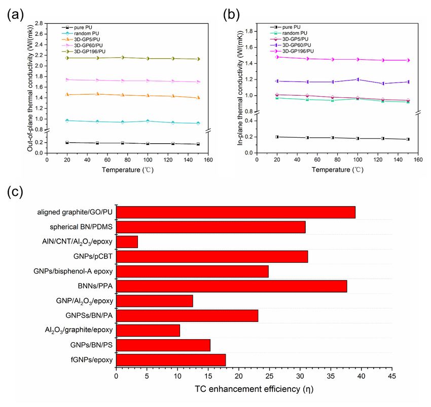
Polymers 2020, 12, 1121                                                                                                    6 of 15

      After infiltration of HTPB prepolymer, this 3D graphite and GO network was embedded into
the HTPB-based PU matrix, and a typical composite with vertically oriented internal structure was
efficiently constructed. The morphology of the 3D-GP/PU composites is shown in Figure 4b–d. It is
evident that graphite flakes and GO sheets dispersed directionally in PU matrices. Nevertheless,
the distance of the oriented graphite flakes suggests clear relevance to temperature, because of the
different sizes of ice crystal, which has been discussed previously. Resulting from the denser network
of graphite and GO, the 3D-GP196/PU composite possessed the most uniform and tightest filler
distribution (Figure 4d). In contrast, the random GP/PU composite without aligned graphite and GO
network exhibited a rough and disordered surface (Figure 4a). This is dramatically different from
3D-GP/PU composites, where the irregular graphite flakes presented random distribution directions
Polymers
and      2020, 12, x FORfillers
     discontinuous        PEER REVIEW
                                in the PU matrix.                                                7 of 16

      Figure 4. SEM images of (a–d) random GP/PU, 3D-GP5/PU, 3D-GP60/PU, and 3D-GP196/PU composites,
      Figure 4. SEM images of (a–d) random GP/PU, 3D-GP5/PU, 3D-GP60/PU, and 3D-GP196/PU
      respectively. Yellow arrows indicate the direction of graphite and GO.
      composites, respectively. Yellow arrows indicate the direction of graphite and GO.
3.2. Thermal Performance of the Composites
3.2. Thermal Performance of the Composites
      In order to achieve the effects of 3D-GP skeletons on heat transfer, thermal conductivity
valuesIn of
         order   to achieve
            random     GP/PU, the3D-GP5/PU,
                                   effects of 3D-GP     skeletonsand
                                                  3D-GP60/PU,       on heat       transfer, thermal
                                                                          3D-GP196/PU           compositesconductivity    values
                                                                                                               were carefully
of randomIt GP/PU,
measured.       is obvious 3D-GP5/PU,        3D-GP60/PU,
                              that the anisotropic     internaland     3D-GP196/PU
                                                                  microstructure              composites
                                                                                         of the   composites  were
                                                                                                                 could carefully
                                                                                                                         lead to
measured.    It is obvious    that  the  anisotropic   internal   microstructure         of  the  composites
anisotropic thermal conductivity values at the different directions. Figure 5a shows the illustration            could   lead to
anisotropic   thermal    conductivity     values   at the  different    directions.     Figure
for in-plane and out-of-plane directions, which are vertical and parallel to the graphite and GO  5a  shows    the  illustration
for in-plane
layers        anddescribed
        that are    out-of-plane     directions,
                                previously.        whichconductivity
                                              Thermal     are vertical and       parallel
                                                                            of these     twoto directions
                                                                                               the graphite  areand   GO layers
                                                                                                                  presented     in
Figure 5b,c, respectively. We can clearly see that random GP/PU composite had a lowerinthermal
that are  described    previously.     Thermal    conductivity    of  these    two    directions     are  presented       Figure
5b,c, respectively.
conductivity    valueWe    can clearly
                       of 0.97  W m−1 see K−1that  random
                                               at the weightGP/PU
                                                               loading composite
                                                                           of 33%, and hadita possessed
                                                                                               lower thermal      conductivity
                                                                                                            the same    thermal
value  of 0.97  W   m −1 K−1 at the  weight   loading   of 33%,  and    it possessed      the
conductivity in in-plane and out-of-plane directions. Meanwhile, the thermal conductivity valuessame   thermal    conductivity
in 3D-GP5/PU,
of in-plane and 3D-GP60/PU,
                    out-of-plane directions.       Meanwhile,
                                      and 3D-GP196/PU            the thermal
                                                             composites        were  conductivity
                                                                                       1.01 W m−1values        of 3D-GP5/PU,
                                                                                                       K−1 , 1.18  W m−1 K−1 ,
3D-GP60/PU,
and  1.48 W m−1   and
                    K−13D-GP196/PU       composites
                         in in-plane direction,     andwere
                                                         1.46 1.01
                                                               W mW   −1 m
                                                                         K−1K
                                                                            −1    −1, 1.18
                                                                                , 1.74  WW m−1 mK−1
                                                                                                  −1 K, and
                                                                                                       −1, and2.15
                                                                                                                1.48WWmm      K−1
                                                                                                                          −1−1K  −1

in out-of-plane
in in-plane direction,    andrespectively,
                   direction,   1.46 W m Kat,the
                                           −1   −1 1.74same
                                                        W mfiller
                                                              −1 K loading.
                                                                  −1 , and 2.15On    W one
                                                                                        m K
                                                                                          −1   −1 in out-of-plane
                                                                                              hand,                   direction,
                                                                                                      3D-GP/PU composites
respectively,   at the  same   filler loading.  On   one hand,   3D-GP/PU          composites
occupied higher thermal conductivity than that of random GP/PU in both in-plane and out-of-plane   occupied    higher   thermal
conductivity than that of random GP/PU in both in-plane and out-of-plane directions. More precisely,
3D-GP196/PU had the highest thermal conductivity, and it increased by 52.6% and 121.6%, in in-
plane and out-of-plane directions, respectively, compared with random GP/PU. On the other hand,
the thermal conductivity values in out-of-plane direction of 3D-GP/PU composites were always
higher than that in in-plane direction. For example, the out-of-plane thermal conductivity of 3D-
GP196/PU was 45.3% higher than in-plane thermal conductivity, as calculated using the measured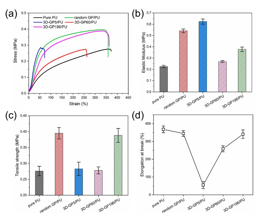
Polymers 2020, 12, 1121                                                                                             7 of 15

directions. More precisely, 3D-GP196/PU had the highest thermal conductivity, and it increased
by 52.6% and 121.6%, in in-plane and out-of-plane directions, respectively, compared with random
GP/PU. On the other hand, the thermal conductivity values in out-of-plane direction of 3D-GP/PU
composites were always higher than that in in-plane direction. For example, the out-of-plane thermal
conductivity
Polymers        ofx3D-GP196/PU
         2020, 12,               was 45.3% higher than in-plane thermal conductivity, as calculated8using
                    FOR PEER REVIEW                                                                  of 16
the measured results.

      Figure 5. (a) Illustration for in-plane and out-of-plane directions and heat transfer pathways. (b,c) In-plane
      Figure 5. (a) Illustration
      and out-of-plane     thermalforconductivities
                                      in-plane and out-of-plane   directions
                                                    of the composites,       and heat transfer
                                                                          respectively.         pathways.
                                                                                         (d) Thermal        (b,c) In-
                                                                                                      conductivity
      plane  and out-of-plane
      enhancement                    thermal
                      of the composites        conductivities
                                           compared            of the
                                                     with the pure   PU.composites, respectively. (d) Thermal
      conductivity enhancement of the composites compared with the pure PU.
      Moreover, according to the tested results, thermal conductivity of pure PU, which is the matrix
of allMoreover,
       the composite  samples,
                  according      was
                             to the  tested  m−1 K−1
                                       0.2 Wresults,     . Thermal
                                                     thermal        conductivity
                                                               conductivity      enhancement
                                                                             of pure PU, which (TCE)   can be
                                                                                                is the matrix
further
of       calculated
   all the compositeand  is shown
                       samples,     in Figure
                                  was   0.2 W 5d.
                                               m Here,
                                                −1          TCE is defined
                                                   K . Thermal
                                                      −1                   as
                                                                    conductivity enhancement (TCE) can be
further calculated and is shown in Figure 5d. Here, TCE is defined as
                                              Kc − Km
                                      TCE =           × 100%                                                            (2)
                                                Km
                                            K − Km
                                    TCE = c          × 100%                                      (2)
where Kc and Km are the thermal conductivity of K
                                                composites and pure PU matrix, respectively. It can
                                                  m
be seen that the TCE of 3D-GP196/PU composite was 640% and 975% in in-plane and out-of-plane,
respectively, which are much higher than that of random GP/PU, 3D-GP5/PU, and 3D-GP60/PU
where Kc and Km are the thermal conductivity of composites and pure PU matrix, respectively. It can
composites. Consequently, 3D-GP196 obviously had the most effective action on improving the thermal
be seen that the TCE of 3D-GP196/PU composite was 640% and 975% in in-plane and out-of-plane,
conductivity of PU matrix.
respectively, which are much higher than that of random GP/PU, 3D-GP5/PU, and 3D-GP60/PU
     The thermal conductivities (TC) of the composites with temperature are shown in Figure 6a,b.
composites. Consequently, 3D-GP196 obviously had the most effective action on improving the
From the results, both the out-of-plane and in-plane TC values present minor decrease with the
thermal conductivity of PU matrix.
     The thermal conductivities (TC) of the composites with temperature are shown in Figure 6a,b.
From the results, both the out-of-plane and in-plane TC values present minor decrease with the
increasing of measurement temperature. That indicates the stable thermal dissipation of the
composites, which is of benefit to the long-term thermal management of devices.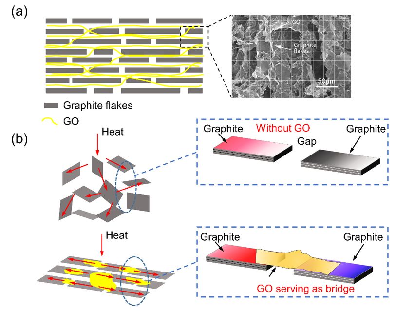
Polymers 2020, 12, 1121                                                                                          8 of 15

 increasing of measurement temperature. That indicates the stable thermal dissipation of the composites,
 which
  Polymersis2020,
             of benefit   toPEER
                  12, x FOR  the long-term
                                  REVIEW thermal management of devices.                          9 of 16

       Figure 6. (a) Out-of-plane and (b) in-plane thermal conductivity with temperature. (c) Comparison of
        Figure 6. (a) Out-of-plane and (b) in-plane thermal conductivity with temperature. (c) Comparison of
       thermal conductivity (TC) enhancement efficiency of reported composites.
        thermal conductivity (TC) enhancement efficiency of reported composites.
       In order to compare with other kinds of thermal conductive composites, TC enhancement efficiency
        In order to compare with other kinds of thermal conductive composites, TC enhancement
 (η) is regarded as an important index, which can be defined as TC enhancement per 1 wt % loading,
  efficiency (η) is regarded as an important index, which can be defined as TC enhancement per 1 wt
 which is given as follows
  % loading, which is given as follows            Kc − Km
                                            η=            × 100                                      (3)
                                                 100WKm
 where η is the TC enhancement efficiencyηand           K c −isKthe
                                                                 m weight loading of fillers. The η values of the
                                                    = W             × 100                                               (3)
 reported composites are summarized in Figure100         6c WK
                                                             and mTable 1. Obviously, the aligned graphite/GO/PU
 composite exhibited the highest η, which means the highest TC at the same loading, across all
 the composites.
  where  η is the TC enhancement efficiency and W is the weight loading of fillers. The η values of the
      Two principal
  reported            reasons
              composites    areshould  be mentioned
                                  summarized               that resulted
                                                     in Figure      6c andin theTable
                                                                                  significant enhancement
                                                                                         1. Obviously,         of thermal
                                                                                                             the   aligned
 conductivity   of the composites.    The    first is  that  most  of  the  graphite   flakes  lay
  graphite/GO/PU composite exhibited the highest η, which means the highest TC at the same loading,along    the direction
 that occupied
  across         higher thermal conductivity (Figure 7a). Thus, the anisotropic thermal performance
         all the composites.
 of graphite was efficiently utilized, and in this direction, we could achieve relatively high thermal
 conductivity. The   second
                  Table       is that of
                        1. Summary    GO thesheets
                                              TC of served
                                                      polymerascomposites
                                                                  the bridges    of with
                                                                             filled graphite   flakes,
                                                                                         different      which were also
                                                                                                   fillers.
 the excellent bridges of heat transfer pathways (Figure 7b). It means that the 3D-GP/PU composites
                         TC of Matrix TC of Composites Loading TC Enhancement                                   References
       Sample heat transfer−1channels
 had continuous                                 composed      of graphite and GO simultaneously. Nonetheless,
                           (W m K−1)             (W m−1 K−1)            (wt %)         Efficiency (η)           and Years
 the random GP/PU had no helpful impact on the GO bridge.
    fGNPs/epoxy                0.23                   1.49               30.00              17.85                2017[66]
     GNPs/BN/PS                0.16                   0.67               21.50              15.33                2015[67]
Al2O3/graphite/epoxy           0.22                   0.64               18.40              10.38                2015[68]
    GNPSs/BN/PA                0.28                   1.69               21.5               23.14                2015[67]
  GNP/Al2O3/epoxy              0.20                    2.2               80.00              12.50                2016[69]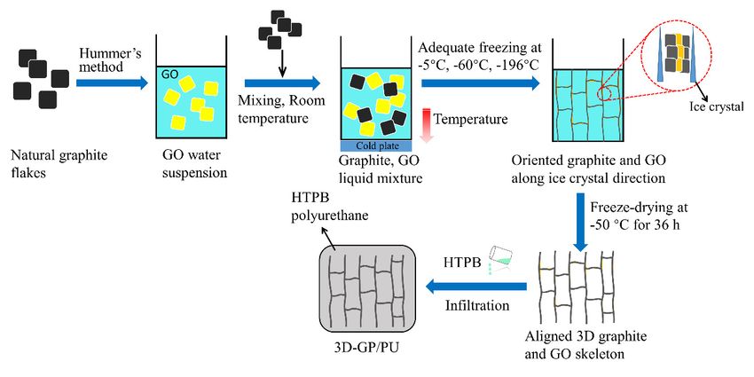
Polymers 2020, 12, x FOR PEER REVIEW                                                                      10 of 16

     BNNs/PPA               0.18               2.89          40.00               37.63                    2019[19]
 Polymers 2020, 12, 1121                                                                                     9 of 15
  GNPs/bisphenol-A
                            0.20               1.70          30.00               24.83                    2016[70]
        epoxy
     GNPs/pCBT              0.24 of the TC of polymer
                Table 1. Summary               2.49 composites
                                                             30.00               31.25
                                                                filled with different  fillers.           2016[34]
AlN/CNT/Al2O3/epoxy          0.2               0.55          50.00                3.50                    2015[71]
                            TC of Matrix    TC of Composites   Loading      TC Enhancement             References
 spherical Sample
           BN/PDMS          0.14
                            (W m−1 K−1 )        2.3m−1 K−1 )
                                               (W            50.00
                                                                (wt %)           30.85 (η)
                                                                               Efficiency              and2019[72]
                                                                                                           Years
       aligned
        fGNPs/epoxy          0.2 0.23          2.151.49          30.00
                                                             25.00                  17.85
                                                                                 39.00                2017
                                                                                                        this[66]
                                                                                                               work
   graphite/GO/PU
        GNPs/BN/PS               0.16              0.67          21.50              15.33             2015 [67]
    Al2 O3 /graphite/epoxy         0.22                0.64            18.40           10.38          2015 [68]
        GNPSs/BN/PA                0.28                1.69             21.5           23.14          2015 [67]
        Two principal reasons should be mentioned that resulted in the significant enhancement of
       GNP/Al2 O3 /epoxy           0.20                 2.2            80.00           12.50          2016 [69]
  thermalBNNs/PPA
             conductivity of the composites.
                                   0.18         The first
                                                       2.89 is that most   of the graphite
                                                                       40.00           37.63flakes lay2019
                                                                                                        along
                                                                                                            [19] the
  direction   that occupied
   GNPs/bisphenol-A    epoxy  higher
                                   0.20thermal conductivity
                                                       1.70      (Figure   7a). Thus, the
                                                                       30.00           24.83anisotropic
                                                                                                      2016thermal
                                                                                                            [70]
         GNPs/pCBT
  performance     of graphite was 0.24                 2.49and in this 30.00
                                    efficiently utilized,                              31.25 achieve2016
                                                                        direction, we could                 [34]
                                                                                                        relatively
    AlN/CNT/Al2 O3 /epoxy           0.2                0.55            50.00            3.50          2015 [71]
  high  thermal
      spherical    conductivity. The
                BN/PDMS            0.14second is that 2.3
                                                        GO sheets served
                                                                       50.00 as the bridges
                                                                                       30.85 of graphite     flakes,
                                                                                                      2019 [72]
  which
   alignedwere   also the excellent 0.2
            graphite/GO/PU           bridges of heat transfer
                                                       2.15      pathways
                                                                       25.00 (Figure 7b).  It means that
                                                                                       39.00               the 3D-
                                                                                                      this work
  GP/PU composites had continuous heat transfer channels composed of graphite and GO
  simultaneously. Nonetheless, the random GP/PU had no helpful impact on the GO bridge.
      In addition, it also can be noticed that the more thermal transfer pathways the composite had,
        In addition, it also can be noticed that the more thermal transfer pathways the composite had,
 the higher thermal conductivity it occupied, which was considerably useful for heat transport. In these
  the higher thermal conductivity it occupied, which was considerably useful for heat transport. In
 four composites, 3D-GP196/PU possessed the densest filler structure benefiting from the architecture
  these four composites, 3D-GP196/PU possessed the densest filler structure benefiting from the
 of 3D-GP196 skeleton. It essentially depended on the extremely low freezing temperature and the
  architecture of 3D-GP196 skeleton. It essentially depended on the extremely low freezing
 smallest ice crystals.
  temperature and the smallest ice crystals.

       Figure 7. (a) Cross-section of the graphite and GO layer, indicating the arrangement. The right graph is
         Figure 7. (a) Cross-section of the graphite and GO layer, indicating the arrangement. The right graph
       the SEM cross-section image. (b) Schematic of the thermal conductive channel of random GP/PU and
         is the SEM cross-section image. (b) Schematic of the thermal conductive channel of random GP/PU
       3D-GP/PU with GO serving as bridge.
         and 3D-GP/PU with GO serving as bridge.
       TGA measurements were performed to investigate the thermal stability of composites as shown
        TGA measurements were performed to investigate the thermal stability of composites as shown
 in Figure 8. It can be seen that 3D-GP196/PU presented the highest thermal stability, related to the close
   in Figure 8. It can be seen that 3D-GP196/PU presented the highest thermal stability, related to the
 bonding between fillers and PU, which impeded the movement and decomposition of PU molecular
   close bonding between fillers and PU, which impeded the movement and decomposition of PU
 chains. Compared with 3D-GP196/PU, the other composites showed worse performance, and the
Polymers 2020, 12, x FOR PEER REVIEW 11 of 16
Polymers 2020, 12, 1121 10 of 15
molecular chains. Compared with 3D-GP196/PU, the other composites showed worse performance,
and the composite with lower freezing temperature exhibited better thermal stability. It can be
composite to
attributed with
thelower freezing
smaller temperature
ice crystals, whichexhibited bettertothermal
is considered stability.
result in It can be
the relatively lowattributed
freedomtostate
the
smaller ice crystals,
of molecular chains. which is considered to result in the relatively low freedom state of molecular chains.
Figure 8. TGA curves of PU and composites.
Figure 8. TGA curves of PU and composites.
3.3. Mechanical Properties of 3D-GP/PU
3.3. Mechanical Properties of 3D-GP/PU
Figure 9 shows the tensile properties of pure PU and its composites fabricated in this work.
Figure 9 shows
Because of special the tensile
internal properties
structure of pure PUthe
of the composites, and its composites
tensile direction isfabricated
vertical tointhe
this work.
graphite
Because
and GO of special
layer. It isinternal
clear thatstructure of the composites,
the composites, including therandom
tensile direction
GP/PU and is vertical to theexhibited
3D-GP/PU, graphite
and GO layer. It is clear that the composites, including random GP/PU
dramatically varied mechanical performances (Figure 9a). For example, random GP/PU had a relatively and 3D-GP/PU, exhibited
dramatically varied compared
high elastic modulus, mechanicalwith performances
3D-GP60/PU(Figure 9a). For example,
and 3D-GP196/PU (Figure 9b).random
That isGP/PU
caused had a
by the
relatively
weak highofelastic
connect 3D-GP60 modulus, compared
and 3D-GP196 with 3D-GP60/PU
skeletons in the tensile and 3D-GP196/PU
direction. Although (Figure
3D-GP5 9b).skeleton
That is
caused by the weak connect of 3D-GP60 and 3D-GP196 skeletons in the
also possesses this weak connect, the elastic modulus of 3D-GP5/PU was higher than random GP/PU. tensile direction. Although
3D-GP5
It might skeleton also possesses
have resulted this weak
from the stress connect, the
concentration elastic
in this modulusowing
composite, of 3D-GP5/PU was higher
to the gathering and
than random GP/PU. It might have resulted from the stress concentration
non-uniform phenomenon in the 3D-GP5 skeleton. Because of that, its tensile strength and elongation atin this composite, owing
to the were
break gathering
muchandlower non-uniform
than random phenomenon in the 3D-GP5(Figure
GP/PU and 3D-GP196/PU skeleton. Because
9c,d). As weofknow,
that, 3D-GP196
its tensile
strength
skeleton and elongation
is more homogenous,at break andwere much lowercomposite
3D-GP196/PU than random GP/PU and
can occupy 3D-GP196/PU
relatively (Figure
high strength of
9c,d). As we know, 3D-GP196 skeleton is more homogenous, and 3D-GP196/PU
0.39 MPa and elongation of 341%. Its strength was enhanced by 40.6% compared to pure PU, and was composite can
occupy relatively
higher than that of high strength of
3D-GP5/PU and 0.39 MPa and elongation
3D-GP60/PU. Meanwhile, of 341%.
its high Its elongation
strength was enhanced
at break by
clearly
40.6%
suggestscompared
the nice to pure PU,
flexibility ofand
this was higher than
composite. Thus,that
the of 3D-GP5/PU
uniform graphite andand 3D-GP60/PU.
GO network Meanwhile,
fabricated
its high elongation at break clearly suggests the nice flexibility of this composite.
via extremely low temperature results in prominent mechanical properties. It is very significant Thus, the uniform
for the
graphite and GO
application of TIM. network fabricated via extremely low temperature results in prominent mechanical
properties. It is very significant for the application of TIM.Polymers2020,
Polymers 2020,12,
12,1121
x FOR PEER REVIEW 12 16
11 of 15
Figure 9. (a) Tensile stress-strain curves of the composites. (b–d) Elastic modulus, tensile strength,
and elongation
Figure at break
9. (a) Tensile of the composites,
stress-strain respectively.
curves of the composites. (b–d) Elastic modulus, tensile strength,
and elongation at break of the composites, respectively.
4. Conclusions
4. Conclusion
In summary, the graphite and GO networks were prepared through a freeze-casting method
usingInthree freezing
summary, thetemperatures,
graphite and and
GO most graphite
networks wereflakes lay along
prepared throughvertical direction with
a freeze-casting GO
method
serving as the bridge and support. The 3D-GP skeleton with low freezing temperature of −196 ◦C
using three freezing temperatures, and most graphite flakes lay along vertical direction with GO
and its PU-based
serving as the bridgecomposite occupied
and support. Thea3D-GP
more uniform
skeletonandwithdenser structure.
low freezing As a result,
temperature of the
−196thermal
°C and
conductivity of 3D-GP196/PU reached 1.48 W m −1 K−1 and 2.15 W m −1 K−1 , and increased by 52.6%
its PU-based composite occupied a more uniform and denser structure. As a result, the thermal
and 121.6%, in in-plane and out-of-plane directions, respectively, compared with
conductivity of 3D-GP196/PU reached 1.48 W m−1 K−1 and 2.15 W m−1 K−1, and increased by 52.6% and random GP/PU.
Moreover,
121.6%, inthis composite
in-plane and presented highdirections,
out-of-plane thermal conductivity
respectively,enhancement
compared efficiency
with randomand thermal
GP/PU.
stability. It was demonstrated that the phenomenon can be attributed to the well-aligned
Moreover, this composite presented high thermal conductivity enhancement efficiency and thermal graphite and
the effect of GO bridges between graphite flakes. Meanwhile, the uniform 3D-GP196
stability. It was demonstrated that the phenomenon can be attributed to the well-aligned graphite skeleton can also
result
and thein excellent
effect of mechanical
GO bridgesproperties. These thermal
between graphite flakes.and mechanical
Meanwhile, theperformances are requisite
uniform 3D-GP196 for
skeleton
ultimate thermal management applicability. This simple and effective approach provides
can also result in excellent mechanical properties. These thermal and mechanical performances are a promising
strategy
requisitetofordevelop high thermal
ultimate performance TIM.
management applicability. This simple and effective approach
provides a promising strategy to develop high performance TIM.
Author Contributions: Data curation, Y.C.; Formal analysis, D.P.; Investigation, Z.W.; Writing—original draft, Z.W.;
Writing—review and editing,
Author Contributions: DataS.H. All authors
curation, have read
Y.C.; Formal and agreed
analysis, to the published
D.P.; Investigation, version
Z.W.; of the manuscript.
Writing—original draft,
Z.W.; Writing—review and editing, S.H. All authors have read
Funding: This research was funded by NSFC grant number 11672002. and agreed to the published version of the
manuscript.
Acknowledgments: The author acknowledges the support from Beijing Electron Spectroscopy Center and
Tsinghua
Funding:University-ULVAC-PHI
This research was fundedJoint
by Analytical
NSFC grant Laboratory for material characterization.
number 11672002.
Conflicts of Interest: The authors declare no conflict of interest.
Acknowledgments: The author acknowledges the support from Beijing Electron Spectroscopy Center and
Tsinghua University-ULVAC-PHI Joint Analytical Laboratory for material characterization.
Conflicts of Interest: The authors declare no conflict of interest.
ReferencePolymers 2020, 12, 1121 12 of 15
References
1. Lian, G.; Tuan, C.C.; Li, L.; Jiao, S.; Wang, Q.; Moon, K.S.; Cui, D.; Wong, C.P. Vertically aligned and
interconnected graphene networks for high thermal conductivity of epoxy composites with ultralow loading.
Chem. Mater. 2016, 28, 6096–6104. [CrossRef]
2. Prasher, R. Thermal boundary resistance and thermal conductivity of multiwalled carbon nanotubes.
Phys. Rev. B 2008, 77, 075424. [CrossRef]
3. Hu, J.; Huang, Y.; Yao, Y.; Pan, G.; Sun, J.; Zeng, X.; Sun, R.; Xu, J.B.; Song, B.; Wong, C.P. Polymer
composite with improved thermal conductivity by constructing a hierarchically ordered three-dimensional
interconnected network of BN. ACS Appl. Mater. Interfaces 2017, 9, 13544–13553. [CrossRef]
4. Feng, C.P.; Bai, L.; Bao, R.; Wang, S.; Liu, Z.; Yang, M. Superior thermal interface materials for thermal
management. Compos. Commun. 2019, 12, 80–85. [CrossRef]
5. Min, S.; Lae, H.; Lee, S.; Gak, B.; Seok, Y.; Chan, J.; Jin, W.; Lee, D.C.; Kim, J.; Yoo, Y. Thermal conductivity of
graphite filled liquid crystal polymer composites and theoretical predictions. Compos. Sci. Technol. 2013, 88,
113–119.
6. Due, J.; Robinson, A.J. Reliability of thermal interface materials: A review. Appl. Therm. Eng. 2013, 50, 455–463.
[CrossRef]
7. Qiu, L.; Scheider, K.; Abu, S.; Sarah, L.; Blair, C.; Feng, Y.; Zhang, X.; Norris, P.M. Thermal transport barrier
in carbon nanotube array nano-thermal interface materials. Carbon 2017, 120, 128–136. [CrossRef]
8. Ma, J.; Shang, T.; Ren, L.; Yao, Y.; Zhang, T.; Xie, J.; Zhang, B. Through-plane assembly of carbon fibers into
3D skeleton achieving enhanced thermal conductivity of a thermal interface material. Chem. Eng. J. 2020,
380, 122550. [CrossRef]
9. An, F.; Li, X.; Min, P.; Li, H.; Dai, Z.; Yu, Z.Z. Highly anisotropic graphene/boron nitride hybrid aerogels with
long-range ordered architecture and moderate density for highly thermally conductive composites. Carbon
2018, 126, 119–127. [CrossRef]
10. Lan, W.; Chen, Y.; Yang, Z.; Han, W.; Zhou, J.; Zhang, Y.; Wang, J.; Tang, G.; Wei, Y.; Dou, W.; et al.
Ultraflexible transparent film heater made of Ag nanowire/PVA composite for rapid-response thermotherapy
pads. ACS Appl. Mater. Interfaces 2017, 9, 6644–6651. [CrossRef]
11. Kim, T.; Kim, Y.W.; Lee, H.S.; Kim, H.; Yang, W.S.; Suh, K.S. Uniformly interconnected silver-nanowire
networks for transparent film heaters. Adv. Funct. Mater. 2013, 23, 1250–1255. [CrossRef]
12. Doganay, D.; Coskun, S.; Kaynak, C.; Unalan, H.E. Electrical, mechanical and thermal properties of aligned
silver nanowire/polylactide nanocomposite films. Compos. Part B Eng. 2016, 99, 288–296. [CrossRef]
13. Yeo, H.; Islam, A.M.; You, N.H.; Ahn, S.; Goh, M.; Hahn, J.R.; Jang, S.G. Characteristic correlation between
liquid crystalline epoxy and alumina filler on thermal conducting properties. Compos. Sci. Technol. 2017, 141,
99–105. [CrossRef]
14. Ren, F.; Zhou, R.; Sun, F.; Ma, H.; Zhou, Z.; Xu, W. Blocked isocyanate silane modified Al2 O3 /polyamide 6
thermally conductive and electrical insulation composites with outstanding mechanical properties. RSC Adv.
2017, 7, 29779–29785. [CrossRef]
15. Ren, L.; Li, Q.; Lu, J.; Zeng, X.; Sun, R.; Wu, J.; Xu, J.B.; Wong, C.P. Enhanced thermal conductivity for
Ag-deposited alumina sphere/epoxy resin composites through manipulating interfacial thermal resistance.
Compos. Part A Appl. Sci. Manuf. 2018, 107, 561–569. [CrossRef]
16. Shen, H.; Guo, J.; Wang, H.; Zhao, N.; Xu, J. Bioinspired modification of h-BN for high thermal conductive
composite films with aligned structure. ACS Appl. Mater. Interfaces 2015, 7, 5701–5708. [CrossRef]
17. Shang, J.; Chen, Y.; Zhou, Y.; Liu, L.; Wang, G.; Li, X.; Kuang, J.; Liu, Q.; Dai, Z.; Miao, H.; et al. Effect of
folded and crumpled morphologies of graphene oxide platelets on the mechanical performances of polymer
nanocomposites. Polymer 2015, 68, 131–139. [CrossRef]
18. Sun, N.; Sun, J.; Zeng, X.; Chen, P.; Qian, J.; Xia, R.; Sun, R. Hot-pressing induced orientation of boron nitride
in polycarbonate composites with enhanced thermal conductivity. Compos. Part A Appl. Sci. Manuf. 2018,
110, 45–52. [CrossRef]
19. Ryu, S.; Oh, H.; Kim, J. Facile liquid-exfoliation process of boron nitride nanosheets for thermal conductive
polyphthalamide composite. Polymers 2019, 11, 1628. [CrossRef]
20. John, B.; Nair, C.P.R.; Ninan, K.N. Effect of nanoclay on the mechanical, dynamic mechanical and thermal
properties of cyanate ester syntactic foams. Mater. Sci. Eng. A 2010, 527, 5435–5443. [CrossRef]Polymers 2020, 12, 1121 13 of 15
21. Mcnamara, A.J.; Joshi, Y.; Zhang, Z.M. Characterization of nanostructured thermal interface materials-A
review. Int. J. Therm. Sci. 2012, 62, 2–11. [CrossRef]
22. Datsyuk, V.; Lisunova, M.; Kasimir, M.; Trotsenko, S.; Gharagozloo-Hubmann, K.; Firkowska, I.; Reich, S.
Thermal transport of oil and polymer composites filled with carbon nanotubes. Appl. Phys. A 2011, 105,
781–788. [CrossRef]
23. Dian, Y.; Lynn, L.; Kong, Q.; Bodelot, L.; Gusarov, B.; Wei, C.; Liang, K.; Lu, C.; Seng, C.; Coquet, P.; et al.
Novel three-dimensional carbon nanotube networks as high performance thermal interface materials. Carbon
2018, 132, 359–369.
24. Keshtkar, M.; Mehdipour, N.; Eslami, H. Thermal conductivity of polyamide-6,6/carbon nanotube composites:
Effects of tube diameter and polymer linkage between tubes. Polymers 2019, 11, 1465. [CrossRef] [PubMed]
25. Shao, L.; Shi, L.; Li, X.; Song, N.; Ding, P. Synergistic effect of BN and graphene nanosheets in 3D framework
on the enhancement of thermal conductive properties of polymeric composites. Compos. Sci. Technol. 2016,
135, 83–91. [CrossRef]
26. Zhang, K.; Tao, P.; Zhang, Y.; Liao, X.; Nie, S. Highly thermal conductivity of CNF/AlN hybrid films for
thermal management of flexible energy storage devices. Carbohydr. Polym. 2019, 213, 228–235. [CrossRef]
[PubMed]
27. Warzoha, R.J.; Fleischer, A.S. Heat flow at nanoparticle interfaces. Nano Energy 2014, 6, 137–158. [CrossRef]
28. Yin, H.; Gao, S.; Liao, C.; Li, C.; Cai, Z.; Xu, Y.; Liu, J. Self-assembly of 3D-graphite block infiltrated phase
change materials with increased thermal conductivity. J. Clean. Prod. 2019, 235, 359–368. [CrossRef]
29. Chung, S.; Kim, H.; Jeong, S.W. Improved thermal conductivity of carbon-based thermal interface materials
by high-magnetic- fi eld alignment. Carbon 2018, 140, 24–29. [CrossRef]
30. Zhou, S.; Xu, J.; Yang, Q.; Chiang, S.; Li, B.; Du, H.; Xu, C.; Kang, F. Experiments and modeling of thermal
conductivity of flake graphite/polymer composites affected by adding carbon-based nano-filler. Carbon 2013,
57, 452–459. [CrossRef]
31. Shahil, K.M.F.; Balandin, A.A. Graphene−multilayer graphene nanocomposites as highly efficient thermal
interface materials. Nano Lett. 2012, 12, 861–867. [CrossRef] [PubMed]
32. Paz, R.; Moriche, R.; Monzón, M.; García, J. Influence of manufacturing parameters and post processing
on the electrical conductivity of extrusion-based 3D printed nanocomposite parts. Polymers 2020, 12, 733.
[CrossRef] [PubMed]
33. Cobos, M.; De-La-Pinta, I.; Quindós, G.; Fernández, M.J.; Fernández, M.D. synthesis, physical, mechanical and
antibacterial properties of nanocomposites based on poly(vinyl alcohol)/graphene oxide-silver nanoparticles.
Polymers 2020, 12, 723. [CrossRef] [PubMed]
34. Colonna, S.; Monticelli, O.; Gomez, J.; Novara, C.; Saracco, G.; Fina, A. Effect of morphology and defectiveness
of graphene-related materials on the electrical and thermal conductivity of their polymer nanocomposites.
Polymer 2016, 102, 292–300. [CrossRef]
35. Mu, C.; Zhang, L.; Song, Y.; Chen, X.; Liu, M.; Wang, F.; Hu, X. Modification of carbon nanotubes by a novel
biomimetic approach towards the enhancement of the mechanical properties of polyurethane. Polymer 2016,
92, 231–238. [CrossRef]
36. Han, N.R.; Cho, J.W. Effect of click coupled hybrids of graphene oxide and thin-walled carbon nanotubes on
the mechanical properties of polyurethane nanocomposites. Compos. Part A Appl. Sci. Manuf. 2018, 109,
376–381. [CrossRef]
37. Blom, P.W.M.; Mihailetchi, V.D.; Koster, L.J.A.; Markov, D.E. Device physics of polymer:Fullerene bulk
heterojunction solar cells. Adv. Mater. 2007, 19, 1551–1566. [CrossRef]
38. Zeng, X.; Yao, Y.; Gong, Z.; Wang, F.; Sun, R.; Xu, J.; Wong, C.P. Ice-templated assembly strategy to construct
3D boron nitride nanosheet networks in polymer composites for thermal conductivity improvement. Small
2015, 11, 6205–6213. [CrossRef]
39. Teng, K.; Ni, Y.; Wang, W.; Wang, H.; Xu, Z.; Chen, L.; Kuang, L.; Ma, M.; Fu, H.; Li, J. Adjustable micro-
structure, higher-level mechanical behavior and conductivities of preformed graphene architecture/epoxy
composites via RTM route. Compos. Part A Appl. Sci. Manuf. 2017, 94, 178–188. [CrossRef]
40. Yao, Y.; Zhu, X.; Zeng, X.; Sun, R.; Xu, J.; Wong, C. Vertically aligned and interconnected sic nanowire networks
leading to significantly enhanced thermal conductivity of polymer composites. ACS Appl. Mater. Interfaces
2018, 10, 9669–9678. [CrossRef]Polymers 2020, 12, 1121 14 of 15
41. Lu, C.; Wai, S.; Du, H.; Li, J.; Gan, L.; Zhang, X.; Chu, X.; Yao, Y.; Li, B.; Kang, F. Thermal conductivity of
electrospinning chain-aligned polyethylene oxide (PEO). Polymer 2017, 115, 52–59. [CrossRef]
42. Sun, R.; Yao, H.; Zhang, H.B.; Li, Y.; Mai, Y.W.; Yu, Z.Z. Decoration of defect-free graphene nanoplatelets
with alumina for thermally conductive and electrically insulating epoxy composites. Compos. Sci. Technol.
2016, 137, 16–23. [CrossRef]
43. Hou, H.; Dai, W.; Yan, Q.; Lv, L.; Alam, F.E.; Yang, M.; Yao, Y.; Zeng, X.; Xu, J.; Yu, J.; et al. Graphene
size-dependent modulation of graphene frameworks contributing to the superior thermal conductivity of
epoxy composites. J. Mater. Chem. A 2018, 6, 12091–12097. [CrossRef]
44. Yuan, C.; Duan, B.; Li, L.; Xie, B.; Huang, M.; Luo, X. Thermal conductivity of polymer-based composites
with magnetic aligned hexagonal boron nitride platelets. ACS Appl. Mater. Interfaces 2015, 7, 13000–13006.
[CrossRef] [PubMed]
45. Kim, K.; Kim, J. Vertical filler alignment of boron nitride/epoxy composite for thermal conductivity
enhancement via external magnetic field. Int. J. Therm. Sci. 2016, 100, 29–36. [CrossRef]
46. Yu, C.; Gong, W.; Zhang, J.; Lv, W.; Tian, W.; Fan, X.; Yao, Y. Hot pressing-induced alignment of hexagonal
boron nitride in SEBS elastomer for superior thermally conductive composites. RSC Adv. 2018, 8, 25835–25845.
[CrossRef]
47. Hamidinejad, S.M.; Chu, R.K.M.; Zhao, B.; Park, C.B.; Filleter, T. Enhanced thermal conductivity of graphene
nanoplatelet-polymer nanocomposites fabricated via supercritical fluid-assisted in situ exfoliation. ACS Appl.
Mater. Interfaces 2018, 10, 1225–1236. [CrossRef]
48. Yoshihara, S.; Sakaguchi, M.; Matsumoto, K.; Tokita, M.; Watanabe, J. Influence of molecular orientation
direction on the in-plane thermal conductivity of polymer/hexagonal boron nitride composites. J. Appl.
Polym. Sci. 2014, 131, 1–7. [CrossRef]
49. Suplicz, A.; Semperger, O.V.; Kovács, J.G. Modeling the Thermal conductivity inhomogeneities of
injection-molded particle-filled composites, caused by segregation. Polymers 2019, 11, 1691. [CrossRef]
50. Jia, Y.; He, H.; Geng, Y.; Huang, B.; Peng, X. High through-plane thermal conductivity of polymer based
product with vertical alignment of graphite flakes achieved via 3D printing. Compos. Sci. Technol. 2017, 145,
55–61. [CrossRef]
51. Nguyen, N.; Park, J.G.; Zhang, S.; Liang, R. Recent advances on 3D printing technique for thermal-related
applications. Adv. Eng. Mater. 2018, 20, 1–10. [CrossRef]
52. Datsyuk, V.; Trotsenko, S.; Reich, S. Carbon-nanotube-polymer nanofibers with high thermal conductivity.
Carbon 2013, 52, 605–608. [CrossRef]
53. Deville, S. Freeze-casting of porous ceramics: A review of current achievements and issues. Adv. Eng. Mater.
2008, 10, 155–169. [CrossRef]
54. Wang, M.; Duan, X.; Xu, Y.; Duan, X. Functional three-dimensional graphene/polymer composites. ACS Nano
2016, 10, 7231–7247. [CrossRef] [PubMed]
55. Suk, J.W.; Piner, R.D.; An, J.; Ruoff, R.S. Mechanical properties of monolayer graphene oxide. ACS Nano 2010,
4, 6557–6564. [CrossRef]
56. Cao, R.; Chen, Z.; Wu, Y.; Tu, Y.; Wu, G.; Yang, X. Precisely controlled growth of poly(ethyl acrylate) chains on
graphene oxide and the formation of layered structure with improved mechanical properties. Compos. Part A
Appl. Sci. Manuf. 2017, 93, 100–106. [CrossRef]
57. Li, J.; Liu, Q.; Ho, D.; Zhao, S.; Wu, S.; Ling, L.; Han, F.; Wu, X.; Zhang, G.; Sun, R.; et al. Three-dimensional
graphene structure for healable flexible electronics based on diels-alder chemistry. ACS Appl. Mater. Interfaces
2018, 10, 9727–9735. [CrossRef] [PubMed]
58. Zhang, X.; Zheng, J.; Fang, H.; Zhang, Y.; Bai, S.; He, G.; Li, K. Catalytic decomposition and crack resistance
of composite energetic material synthesized by recrystallizing with graphene oxide. Compos. Part A Appl.
Sci. Manuf. 2019, 118, 90–98. [CrossRef]
59. Zhang, M.; Yan, H.; Yang, X.; Liu, C. Effect of functionalized graphene oxide with a hyperbranched
cyclotriphosphazene polymer on mechanical and thermal properties of cyanate ester composites. RSC Adv.
2014, 4, 45930–45938. [CrossRef]
60. Alipoori, S.; Torkzadeh, M.M.; Moghadam, M.H.M.; Mazinani, S.; Aboutalebi, S.H.; Sharif, F. Graphene oxide:
An effective ionic conductivity promoter for phosphoric acid-doped poly (vinyl alcohol) gel electrolytes.
Polymer 2019, 184, 121908. [CrossRef]Polymers 2020, 12, 1121 15 of 15
61. Zhang, X.; Zheng, J.; Fang, H.; Zhang, Y.; Bai, S. Surface modified graphene oxide cross-linking with
hydroxyl-terminated polybutadiene polyurethane: Effects on structure and properties. Compos. Part A Appl.
Sci. Manuf. 2017, 103, 208–218. [CrossRef]
62. Zhang, X.; Liu, D.; Yang, L.; Zhou, L.; You, T. Self-assembled three-dimensional graphene-based materials for
dye adsorption and catalysis. J. Mater. Chem. A 2015, 3, 10031–10037. [CrossRef]
63. Yang, F.J.; Huang, Y.F.; Zhang, M.Q.; Ruan, W.H. Significant improvement of ionic conductivity of
high-graphene oxide-loading ice-templated poly (ionic liquid) nanocomposite electrolytes. Polymer 2018,
153, 438–444. [CrossRef]
64. Zhang, X.; Zheng, J.; Fang, H.; Zhang, Y.; Bai, S.; He, G. Al2 O3 /graphene reinforced bio-inspired interlocking
polyurethane composites with superior mechanical and thermal properties for solid propulsion fuel.
Compos. Sci. Technol. 2018, 167, 42–52. [CrossRef]
65. Marcano, D.C.; Kosynkin, D.V.; Berlin, J.M.; Sinitskii, A.; Sun, Z.Z.; Slesarev, A.; Alemany, L.B.; Lu, W.;
Tour, J.M. Improved synthesis of graphene oxide. ACS Nano 2010, 4, 4806–4814. [CrossRef] [PubMed]
66. Gu, J.; Liang, C.; Zhao, X.; Gan, B.; Qiu, H.; Guo, Y.; Yang, X.; Zhang, Q.; Wang, D.Y. Highly thermally
conductive flame-retardant epoxy nanocomposites with reduced ignitability and excellent electrical
conductivities. Compos. Sci. Technol. 2017, 139, 83–89. [CrossRef]
67. Cui, X.; Ding, P.; Zhuang, N.; Shi, L.; Song, N.; Tang, S. Thermal conductive and mechanical properties of
polymeric composites based on solution-exfoliated boron nitride and graphene nanosheets: A morphology-
promoted synergistic effect. ACS Appl. Mater. Interfaces 2015, 7, 19068–19075. [CrossRef]
68. Tang, D.; Su, J.; Yang, Q.; Kong, M.; Zhao, Z.; Huang, Y.; Liao, X.; Liu, Y. Preparation of alumina-coated graphite
for thermally conductive and electrically insulating epoxy composites. RSC Adv. 2015, 5, 55170–55178.
[CrossRef]
69. Guan, F.L.; Gui, C.X.; Zhang, H.B.; Jiang, Z.G.; Jiang, Y.; Yu, Z.Z. Enhanced thermal conductivity and
satisfactory flame retardancy of epoxy/alumina composites by combination with graphene nanoplatelets and
magnesium hydroxide. Compos. Part B Eng. 2016, 98, 134–140. [CrossRef]
70. Gu, J.; Yang, X.; Lv, Z.; Li, N.; Liang, C.; Zhang, Q. Functionalized graphite nanoplatelets/epoxy resin
nanocomposites with high thermal conductivity. Int. J. Heat Mass Transf. 2016, 92, 15–22. [CrossRef]
71. Gao, Z.; Zhao, L. Effect of nano-fillers on the thermal conductivity of epoxy composites with micro-Al2 O3
particles. Mater. Des. 2015, 66, 176–182. [CrossRef]
72. Ren, L.; Zeng, X.; Sun, R.; Xu, J.B.; Wong, C.P. Spray-assisted assembled spherical boron nitride as fillers for
polymers with enhanced thermally conductivity. Chem. Eng. J. 2019, 370, 166–175. [CrossRef]
© 2020 by the authors. Licensee MDPI, Basel, Switzerland. This article is an open access
article distributed under the terms and conditions of the Creative Commons Attribution
(CC BY) license (http://creativecommons.org/licenses/by/4.0/).You can also read