Final draft ETSI EN 303 347-3 V1.1.5 (2021-03) - HARMONISED EUROPEAN STANDARD Meteorological Radars
←
→
Page content transcription
If your browser does not render page correctly, please read the page content below
Final draft ETSI   EN 303 347-3 V1.1.5 (2021-03)

HARMONISED EUROPEAN STANDARD

                    Meteorological Radars;
     Harmonised Standard for access to radio spectrum;
        Part 3: Meteorological Radar Sensor operating
   in the frequency band 9 300 MHz to 9 500 MHz (X band)
2              Final draft ETSI EN 303 347-3 V1.1.5 (2021-03)

                                                            Reference
                                                   DEN/ERM-TGAERO-42-3

                                                            Keywords
                                              harmonised standard, radar, radio

                                                               ETSI

                                                  650 Route des Lucioles
                                         F-06921 Sophia Antipolis Cedex - FRANCE

                                      Tel.: +33 4 92 94 42 00 Fax: +33 4 93 65 47 16

                                             Siret N° 348 623 562 00017 - NAF 742 C
                                            Association à but non lucratif enregistrée à la
                                            Sous-Préfecture de Grasse (06) N° 7803/88

                                                     Important notice

                                     The present document can be downloaded from:
                                          http://www.etsi.org/standards-search

The present document may be made available in electronic versions and/or in print. The content of any electronic and/or
print versions of the present document shall not be modified without the prior written authorization of ETSI. In case of any
   existing or perceived difference in contents between such versions and/or in print, the prevailing version of an ETSI
                    deliverable is the one made publicly available in PDF format at www.etsi.org/deliver.

   Users of the present document should be aware that the document may be subject to revision or change of status.
                   Information on the current status of this and other ETSI documents is available at
                                 https://portal.etsi.org/TB/ETSIDeliverableStatus.aspx

         If you find errors in the present document, please send your comment to one of the following services:
                                  https://portal.etsi.org/People/CommiteeSupportStaff.aspx

                                                Copyright Notification

  No part may be reproduced or utilized in any form or by any means, electronic or mechanical, including photocopying
                          and microfilm except as authorized by written permission of ETSI.
            The content of the PDF version shall not be modified without the written authorization of ETSI.
                    The copyright and the foregoing restriction extend to reproduction in all media.

                                                        © ETSI 2021.
                                                     All rights reserved.

DECT™, PLUGTESTS™, UMTS™ and the ETSI logo are trademarks of ETSI registered for the benefit of its Members.
           3GPP™ and LTE™ are trademarks of ETSI registered for the benefit of its Members and
                                  of the 3GPP Organizational Partners.
             oneM2M™ logo is a trademark of ETSI registered for the benefit of its Members and
                                         of the oneM2M Partners.
           GSM® and the GSM logo are trademarks registered and owned by the GSM Association.

                                                               ETSI
3 Final draft ETSI EN 303 347-3 V1.1.5 (2021-03)
Contents
Intellectual Property Rights ................................................................................................................................5
Foreword.............................................................................................................................................................5
Modal verbs terminology....................................................................................................................................6
1 Scope ........................................................................................................................................................7
2 References ................................................................................................................................................7
2.1 Normative references ......................................................................................................................................... 7
2.2 Informative references ........................................................................................................................................ 8
3 Definition of terms, symbols and abbreviations .......................................................................................8
3.1 Terms.................................................................................................................................................................. 8
3.2 Symbols ............................................................................................................................................................ 10
3.3 Abbreviations ................................................................................................................................................... 10
4 Technical requirements specifications ...................................................................................................11
4.1 Environmental profile....................................................................................................................................... 11
4.2 Conformance requirements .............................................................................................................................. 11
4.2.1 Transmitter requirements ............................................................................................................................ 11
4.2.1.1 Frequency Tolerance ............................................................................................................................. 11
4.2.1.1.1 Definition......................................................................................................................................... 11
4.2.1.1.2 Limits .............................................................................................................................................. 11
4.2.1.1.3 Conformance ................................................................................................................................... 11
4.2.1.2 Transmitter output power ...................................................................................................................... 11
4.2.1.2.1 Definition......................................................................................................................................... 11
4.2.1.2.2 Limits .............................................................................................................................................. 12
4.2.1.2.3 Conformance ................................................................................................................................... 12
4.2.1.3 Measured B-40 Bandwidth ..................................................................................................................... 12
4.2.1.3.1 Definition......................................................................................................................................... 12
4.2.1.3.2 Limits .............................................................................................................................................. 12
4.2.1.3.3 Conformance ................................................................................................................................... 12
4.2.1.4 Out-of-Band emissions.......................................................................................................................... 12
4.2.1.4.1 Definition......................................................................................................................................... 12
4.2.1.4.2 Limits .............................................................................................................................................. 13
4.2.1.4.3 Conformance ................................................................................................................................... 14
4.2.1.5 Spurious emissions ................................................................................................................................ 14
4.2.1.5.1 Definition......................................................................................................................................... 14
4.2.1.5.2 Limits .............................................................................................................................................. 15
4.2.1.5.3 Conformance ................................................................................................................................... 15
4.2.1.6 Stand-by Mode emissions ..................................................................................................................... 16
4.2.1.6.1 Definition......................................................................................................................................... 16
4.2.1.6.2 Limits .............................................................................................................................................. 16
4.2.1.6.3 Conformance ................................................................................................................................... 16
4.2.2 Receiver Requirements ............................................................................................................................... 16
4.2.2.1 Noise Figure .......................................................................................................................................... 16
4.2.2.1.1 Definition......................................................................................................................................... 16
4.2.2.1.2 Limits .............................................................................................................................................. 16
4.2.2.1.3 Conformance ................................................................................................................................... 16
4.2.2.2 Receiver Selectivity .............................................................................................................................. 16
4.2.2.2.1 Definition......................................................................................................................................... 16
4.2.2.2.2 Limits .............................................................................................................................................. 16
4.2.2.2.3 Conformance ................................................................................................................................... 18
4.2.2.3 Receiver Compression Level ................................................................................................................ 18
4.2.2.3.1 Definition......................................................................................................................................... 18
4.2.2.3.2 Limits .............................................................................................................................................. 19
4.2.2.3.3 Conformance ................................................................................................................................... 19
5 Testing for compliance with technical requirements..............................................................................19
5.1 General requirements ....................................................................................................................................... 19
ETSI4 Final draft ETSI EN 303 347-3 V1.1.5 (2021-03)
5.2 Environmental conditions for testing ............................................................................................................... 20
5.2.1 Test Conditions ........................................................................................................................................... 20
5.2.2 Normal temperature and humidity .............................................................................................................. 20
5.2.3 Normal test power supply ........................................................................................................................... 20
5.3 Radio test suites ................................................................................................................................................ 20
5.3.1 Transmitter test specification ...................................................................................................................... 20
5.3.1.1 Frequency Tolerance ............................................................................................................................. 20
5.3.1.2 Transmitter Power ................................................................................................................................. 21
5.3.1.3 Measured B-40 Bandwidth ..................................................................................................................... 21
5.3.1.4 Out-of-Band emissions.......................................................................................................................... 22
5.3.1.5 Spurious emissions ................................................................................................................................ 23
5.3.1.6 Stand-by Mode Emissions..................................................................................................................... 25
5.3.2 Receiver Test specification ......................................................................................................................... 25
5.3.2.1 Noise Figure .......................................................................................................................................... 25
5.3.2.2 Receiver Selectivity .............................................................................................................................. 26
5.3.2.2.1 General ............................................................................................................................................ 26
5.3.2.2.2 Receiver unwanted Signal Selectivity ............................................................................................. 26
5.3.2.3 Receiver Compression Level ................................................................................................................ 27
5.3.2.3.1 General ............................................................................................................................................ 27
5.3.2.3.2 Receiver Compression Level ........................................................................................................... 27
Annex A (informative): Relationship between the present document and the essential
requirements of Directive 2014/53/EU .........................................................28
Annex B (normative): Calculation of the -40 dB Bandwidth ...........................................................29
Annex C (normative): Operating frequency and transmitter power measurement setup ............31
Annex D (normative): Spurious and OoB emission measurement setup ........................................32
Annex E (normative): Receiver selectivity and compression level measurement setup ................33
Annex F (informative): Maximum Measurement Uncertainty ..........................................................34
Annex G (informative): WR90/WG16 waveguide characteristics......................................................35
Annex H (informative): Checklist .........................................................................................................37
History ..............................................................................................................................................................39
ETSI5 Final draft ETSI EN 303 347-3 V1.1.5 (2021-03)
Intellectual Property Rights
Essential patents
IPRs essential or potentially essential to normative deliverables may have been declared to ETSI. The information
pertaining to these essential IPRs, if any, is publicly available for ETSI members and non-members, and can be found
in ETSI SR 000 314: "Intellectual Property Rights (IPRs); Essential, or potentially Essential, IPRs notified to ETSI in
respect of ETSI standards", which is available from the ETSI Secretariat. Latest updates are available on the ETSI Web
server (https://ipr.etsi.org/).
Pursuant to the ETSI IPR Policy, no investigation, including IPR searches, has been carried out by ETSI. No guarantee
can be given as to the existence of other IPRs not referenced in ETSI SR 000 314 (or the updates on the ETSI Web
server) which are, or may be, or may become, essential to the present document.
Trademarks
The present document may include trademarks and/or tradenames which are asserted and/or registered by their owners.
ETSI claims no ownership of these except for any which are indicated as being the property of ETSI, and conveys no
right to use or reproduce any trademark and/or tradename. Mention of those trademarks in the present document does
not constitute an endorsement by ETSI of products, services or organizations associated with those trademarks.
Foreword
This final draft Harmonised European Standard (EN) has been produced by ETSI Technical Committee
Electromagnetic compatibility and Radio spectrum Matters (ERM), and is now submitted for the Vote phase of the
ETSI standards EN Approval Procedure.
The present document has been prepared under the Commission's standardisation request C (2015) 5376 final [i.5] to
provide one voluntary means of conforming to the essential requirements of Directive 2014/53/EU on the harmonisation
of the laws of the Member States relating to the making available on the market of radio equipment and repealing
Directive 1999/5/EC [i.1].
Once the present document is cited in the Official Journal of the European Union under that Directive, compliance with
the normative clauses of the present document given in Table A.1 confers, within the limits of the scope of the present
document, a presumption of conformity with the corresponding essential requirements of that Directive and associated
EFTA regulations.
The present document is part 3 of a multi-part deliverable covering meteorological radar systems for different frequency
bands, as identified below:
Part 1: "Meteorological Radar Sensor operating in the frequency band 2 700 MHz to 2 900 MHz (S band)";
Part 2: "Meteorological Radar Sensor operating in the frequency band 5 250 MHz to 5 850 MHz (C band)";
Part 3: "Meteorological Radar Sensor operating in the frequency band 9 300 MHz to 9 500 MHz
(X band)".
Proposed national transposition dates
Date of latest announcement of this EN (doa): 3 months after ETSI publication
Date of latest publication of new National Standard
or endorsement of this EN (dop/e): 6 months after doa
Date of withdrawal of any conflicting National Standard (dow): 18 months after doa
ETSI6 Final draft ETSI EN 303 347-3 V1.1.5 (2021-03)
Modal verbs terminology
In the present document "shall", "shall not", "should", "should not", "may", "need not", "will", "will not", "can" and
"cannot" are to be interpreted as described in clause 3.2 of the ETSI Drafting Rules (Verbal forms for the expression of
provisions).
"must" and "must not" are NOT allowed in ETSI deliverables except when used in direct citation.
ETSI7 Final draft ETSI EN 303 347-3 V1.1.5 (2021-03)
1 Scope
The present document specifies technical characteristics and methods of measurements for X band meteorological radar
systems intended for the surveillance and classification of hydrometeors with the following characteristics:
• Operating in the following frequency range:
- 9 300 MHz to 9 500 MHz.
• Utilizing unmodulated pulses or phase/frequency modulated pulses also known as pulse compression.
• The maximum output power (PEP) is not greater than 250 kW (i.e. 84 dBm).
• The transceiver antenna connection and its feeding RF line use a hollow metallic rectangular waveguide.
• The antenna rotates and can be changed in elevation.
• The used waveguide is WR90/WG16 waveguide according to IEC 60153-2 [i.2] with a minimum length
between the output of the transmitter and the input of the antenna of 915 mm (20 times the wavelength of the
waveguide cut-off frequency).
• The antenna feed is waveguide based and the antenna is passive.
• The orientation of the transmitted field from the antenna can be vertical or horizontal polarized or it can be
both simultaneously.
• At the transceiver output an RF circulator is used.
NOTE 1: Since at the transceiver output an RF circulator is used, it is assumed that the transceiver characteristics
remain independent from the antenna.
NOTE 2: According to provision 5.475B of the ITU Radio Regulations [i.7], ground-based radars used for
meteorological purposes in the band 9 300 MHz to 9 500 MHz have priority over other radiolocation
uses.
NOTE 3: Further technical and operational characteristics of meteorological radar systems can be found in
Recommendation ITU-R M.1849-1 [i.3].
NOTE 4: The relationship between the present document and essential requirements of article 3.2 of Directive
2014/53/EU [i.1] is given in Annex A.
2 References
2.1 Normative references
References are either specific (identified by date of publication and/or edition number or version number) or
non-specific. For specific references, only the cited version applies. For non-specific references, the latest version of the
referenced document (including any amendments) applies.
Referenced documents which are not found to be publicly available in the expected location might be found at
https://docbox.etsi.org/Reference/.
NOTE: While any hyperlinks included in this clause were valid at the time of publication, ETSI cannot guarantee
their long term validity.
The following referenced documents are necessary for the application of the present document.
[1] ERC/Recommendation 74-01 (2019): "Unwanted emissions in the spurious domain".
[2] ECC/Recommendation (02)05 (2012): "Unwanted emissions".
ETSI8 Final draft ETSI EN 303 347-3 V1.1.5 (2021-03)
[3] Recommendation ITU-R M.1177-4 (04/2011): "Techniques for measurement of unwanted
emissions of radar systems".
2.2 Informative references
References are either specific (identified by date of publication and/or edition number or version number) or
non-specific. For specific references, only the cited version applies. For non-specific references, the latest version of the
referenced document (including any amendments) applies.
NOTE: While any hyperlinks included in this clause were valid at the time of publication, ETSI cannot guarantee
their long term validity.
The following referenced documents are not necessary for the application of the present document but they assist the
user with regard to a particular subject area.
[i.1] Directive 2014/53/EU of the European Parliament and of the Council of 16 April 2014 on the
harmonisation of the laws of the Member States relating to the making available on the market of
radio equipment and repealing Directive 1999/5/EC.
[i.2] IEC 60153-2 (Edition 3.0, 2016): "Hollow metallic waveguides. Part 2: Relevant specifications for
ordinary rectangular waveguides".
[i.3] Recommendation ITU-R M.1849-1 (09/2015): "Technical and operational aspects of ground-based
meteorological radars".
[i.4] Recommendation ITU-R SM.1541-6 (08/2015): "Unwanted emissions in the out-of-band domain".
[i.5] Commission Implementing Decision C(2015) 5376 final of 4.8.2015 on a standardisation request
to the European Committee for Electrotechnical Standardisation and to the European
Telecommunications Standards Institute as regards radio equipment in support of Directive
2014/53/EU of the European Parliament and of the Council.
[i.6] ETSI EG 203 336 (V1.2.1) (2020-05): "Guide for the selection of technical parameters for the
production of Harmonised Standards covering article 3.1(b) and article 3.2 of Directive
2014/53/EU".
[i.7] ITU Radio Regulations (2020).
3 Definition of terms, symbols and abbreviations
3.1 Terms
For the purposes of the present document, the following terms apply:
active state: state which produces the authorized emission
allocated band: frequency span that regionally or nationally is allocated to one or more radio services on a primary or
secondary basis
NOTE: A table of national frequency allocations are normally available from the radio authority for each national
state. A generic frequency allocation table is also available in the ITU Radio Regulations [i.7].
assigned frequency: centre of the frequency band assigned to a station
NOTE: This definition is taken from the ITU Radio Regulations [i.7].
assigned frequency band: frequency band within which the emission of a station is authorized
NOTE 1: The width of the band equals the necessary bandwidth plus twice the absolute value of the frequency
tolerance. Where space stations are concerned, the assigned frequency band includes twice the maximum
Doppler shift that may occur in relation to any point of the Earth's surface.
ETSI9 Final draft ETSI EN 303 347-3 V1.1.5 (2021-03)
NOTE 2: This definition is taken from the ITU Radio Regulations [i.7].
characteristic frequency: frequency which can be easily identified and measured in a given emission
NOTE 1: A carrier frequency may, for example, be designed as the characteristic frequency.
NOTE 2: This definition is taken from the ITU Radio Regulations [i.7].
declared band: band or bands within which the product under test is declared to operate in the applicable operating
modes
NOTE: The declared band for a given region or country is always contained within the allocated band.
frequency tolerance: maximum permissible departure by the centre frequency of the frequency band occupied by an
emission from the assigned frequency or, by the characteristic frequency of an emission from the reference frequency
NOTE 1: The frequency tolerance is expressed in parts in 106 or in Hertz.
NOTE 2: This definition is taken from the ITU Radio Regulations [i.7].
idle/standby state: state where the transmitter is available for operation but is not in the active state
necessary bandwidth BN: width of the frequency band which is just sufficient to ensure the transmission of
information at the rate and with the quality required under specified conditions for a given class of emission
NOTE: This definition is taken from the ITU Radio Regulations [i.7].
occupied bandwidth: width of a frequency band such that, below the lower and above the upper frequency limits, the
mean powers emitted are each equal to a specified percentage β/2 of the total mean power of a given emission
NOTE 1: Unless otherwise specified in a Recommendation ITU-R for the appropriate class of emission, the value
of β/2 should be taken as 0,5 %.
NOTE 2: This definition is taken from the ITU Radio Regulations [i.7].
operating mode: predefined configuration for a given service accessible to the operator of the radar system
NOTE 1: Several operating modes may be available.
NOTE 2: Changing operating mode might affect the radio characteristics of the radar system.
out-of-band emission: emission on a frequency or frequencies immediately outside the necessary bandwidth which
results from the modulation process, but excluding spurious emissions
NOTE: This definition is taken from the ITU Radio Regulations [i.7].
peak envelope power (of a radio transmitter): average power supplied to the antenna transmission line by a
transmitter during one radio frequency cycle at the crest of the modulation envelope taken under normal operating
conditions
NOTE: This definition is taken from the ITU Radio Regulations [i.7].
product configuration: hardware variant of the same typology of system under test (e.g. different power outputs,
magnetrons)
pulse duration: time in seconds between the 50 % amplitude (voltage) points of a transmitted pulse
pulse rise time: time taken for the leading edge of the pulse to increase from 10 % to 90 % of the maximum amplitude
(voltage) in seconds
receiver selectivity: ability of a receiver to detect and decode a desired signal in the presence of an unwanted
interfering signal outside the B-40 bandwidth
ETSI10 Final draft ETSI EN 303 347-3 V1.1.5 (2021-03)
reference frequency: frequency having a fixed and specified position with respect to the assigned frequency
NOTE 1: The displacement of this frequency with respect to the assigned frequency has the same absolute value
and sign that the displacement of the characteristic frequency has with respect to the centre of the
frequency band occupied by the emission.
NOTE 2: This definition is taken from the ITU Radio Regulations [i.7].
spurious emission: emission on a frequency or frequencies which are outside the necessary bandwidth and the level of
which may be reduced without affecting the corresponding transmission of information
NOTE 1: Spurious emissions include harmonic emissions, parasitic emissions, intermodulation products and
frequency conversion products, but exclude out-of-band emissions.
NOTE 2: This definition is taken from the ITU Radio Regulations [i.7].
system coupler: directional waveguide coupler with forward and reverse port or only a forward port
NOTE: The system coupler is inserted in the waveguide run between the circulator and the antenna but not
directly located behind the antenna. Usually it is located very close behind the circulator.
trapezoidal pulse: pulse which linearly rises to some value and remains constant at this value for some time and falls
linearly to the original value at the end of the pulse
3.2 Symbols
For the purposes of the present document, the following symbols apply:
B-40 -40 dB bandwidth
BC Chirp bandwidth
BN Necessary bandwidth
dB/dec dB per decade
dBpp dB with respect to peak power
fc characteristic frequency
fIF IF frequency
fImage Image frequency
ft transmitter frequency tolerance
k Boltzmann's constant
t Pulse duration
tr Pulse rise time
3.3 Abbreviations
For the purposes of the present document, the following abbreviations apply:
A/D Analog to Digital converter
AC Alternating Current
AM Amplitude Modulation
CW Continuous Wave
EFTA European Free Trade Association
EIA Electronic Industries Alliance
EM Electromagnetic
ENR Excessive Noise Ratio
FM Frequency Modulation
IEC International Electrotechnical Commission
IF Intermediate Frequency
LNA Low Noise Amplifier
LNFE Low Noise Front End
MDS Minimum Detectable Signal
MW MegaWatt
ETSI11 Final draft ETSI EN 303 347-3 V1.1.5 (2021-03)
na not applicable
OoB Out-of-Band
PEP Peak Envelope Power
PM Phase Modulation
ppm part(s) per million
PRF Pulse Repetition Frequency
RF Radio Frequency
UK United Kingdom
WG Waveguide
WR Waveguide Rectangular
4 Technical requirements specifications
4.1 Environmental profile
The technical requirements of the present document apply under the environmental profile for operation of the
equipment, which shall be in accordance with its intended use, but as a minimum, shall be that specified in the test
conditions contained in the present document. The equipment shall comply with all the technical requirements of the
present document at all times when operating within the boundary limits of the operational environmental profile
defined by its intended use.
4.2 Conformance requirements
4.2.1 Transmitter requirements
4.2.1.1 Frequency Tolerance
4.2.1.1.1 Definition
The transmitter of a pulsed radar system produces microwave pulses, which cause a broad frequency spectrum
depending on the pulse duration. The operating frequency is the frequency of the microwave emission during the
transmitting pulse and is represented by the spectral line of highest amplitude. For phase/frequency modulated radar
systems the operating frequency is to be understood as the centre between the highest and lowest transmitted frequency.
The frequency tolerance is the maximum permissible departure from the operating frequency.
4.2.1.1.2 Limits
The frequency tolerance for meteorological radar systems at the defined operating frequency shall not exceed
1 250 ppm.
NOTE: This value is specified in Appendix 2 of ITU Radio Regulations [i.7].
4.2.1.1.3 Conformance
The conformance tests are specified in clause 5.3.1.1.
The results obtained for all available pulse length settings shall not exceed the limits specified in clause 4.2.1.1.2.
4.2.1.2 Transmitter output power
4.2.1.2.1 Definition
The transmitter power is considered to be the peak value (PEP) of the transmitter pulse power during the transmission
pulse.
ETSI12 Final draft ETSI EN 303 347-3 V1.1.5 (2021-03)
4.2.1.2.2 Limits
The transmitter power shall not exceed 250 kW (i.e. 84 dBm).
4.2.1.2.3 Conformance
The conformance tests are specified in clause 5.3.1.2.
The results obtained for all available pulse length settings shall not exceed the limits specified in clause 4.2.1.2.2.
4.2.1.3 Measured B-40 Bandwidth
4.2.1.3.1 Definition
The measured -40 dB bandwidth is the measured bandwidth of the emission 40 dB below the PEP.
4.2.1.3.2 Limits
For all radar types covered by the present document the measured B-40 bandwidth of the signal shall be contained
completely within the declared band in all operating modes.
In case of multiple carrier-frequencies, all measured -40 dB emissions shall be contained in the declared band.
NOTE: The declared band is always contained in the 9 300 MHz to 9 500 MHz frequency range.
4.2.1.3.3 Conformance
The conformance tests are specified in clause 5.3.1.3.
The results obtained shall not exceed the limits specified in clause 4.2.1.3.2.
4.2.1.4 Out-of-Band emissions
4.2.1.4.1 Definition
Out-of-Band emissions refer to emissions in the region between the calculated -40 dB bandwidth and the spurious
region (see clause 4.2.1.5.1 for the definition of spurious region).
For meteorological radar systems with multiple pulse length, the B-40 bandwidth is calculated for each individual used
pulse length and the maximum B-40 bandwidth obtained is used to establish the shape of the emission mask.
NOTE: The shortest pulse length used is usually 500 ns.
For radars with multiple carrier frequencies, the overall emission mask is obtained by superimposing the emission
masks of each individual carrier frequency. An example can be seen in Figure 1.
The applicable formulae for the calculation of the B-40 bandwidth are described in Annex B.
ETSI13 Final draft ETSI EN 303 347-3 V1.1.5 (2021-03)
Power
B-40 B-40
40 dB
100 dB / 90 dB / -30 dBm
OoB mask from ECC
Recommendation (02)05
[2]
Spurious limit from ERC
Recommendation 74-01
[1]
Frequency
Figure 1: Example of superimposed (combined) mask from two carrier frequencies
4.2.1.4.2 Limits
Depending on the PEP power the maximum OoB emission power level shall not exceed the limits stated in Table 1 or
Table 2 and shall not exceed the corresponding mask depicted in Figure 2 as specified in Annex 2 in
ECC/Recommendation (02)05 [2]. The roll-off of the OoB mask beyond the B-40 bandwidth in relation to B-40 is
specified as follows:
• The mask has a roll-off at 30 dB/dec from the calculated (identified) B-40 bandwidth to a level of -70 dBpp.
• The mask then continues to roll-off at 60 dB/dec to a spurious emission limit level of -100 dBpp or -90 dBpp
with regard to the PEP.
NOTE 1: The -100 dBpp mask corresponds to the dashed line in Figure A2.1c and the -90 dBpp corresponds to the
dashed line in Figure A2.1b of unwanted emissions in Annex 2 of the ECC/Recommendation (02)05 [2].
NOTE 2: ERC/Recommendation 74-01 [1] stipulates in its Table 15 for meteorological radars a spurious emission
limit of "-30 dBm or 100 dB/90 dB below PEP, whichever is less stringent".
Table 1: Limits for Out-of-Band emissions for a PEP greater than 150 kW
Multiple of the Limit Slope
B-40 bandwidth dBpp dB/decade
0,5 -40 -∞
0,5 to 5 -40 to -70 -30
5 to 10,8 -70 to -90 -60
ETSI14 Final draft ETSI EN 303 347-3 V1.1.5 (2021-03)
Table 2: Limits for Out-of-Band emissions for a PEP equal to or less than 150 kW
Multiple of the Limit Slope
B-40 bandwidth dBpp dB/decade
0,5 -40 -∞
0,5 to 5 -40 to -70 -30
5 to 15,8 -70 to -100 or -30 dBm, see note -60
NOTE: -70 dBpp to -100 dBpp or -30 dBm whichever is less stringent.
Figure 2: Unwanted emission limit masks
4.2.1.4.3 Conformance
The conformance tests are specified in clause 5.3.1.4.
The results obtained shall not exceed the limits specified in clause 4.2.1.4.2.
4.2.1.5 Spurious emissions
4.2.1.5.1 Definition
Spurious emissions are unwanted emissions in the spurious domain. For active transmitters, the spurious domain is all
frequencies outside the OoB domain as shown in Figure 3 below.
They include:
• harmonic emissions (whole multiples of the operating frequency);
• parasitic emissions (independent, accidental);
• intermodulation (between oscillator- and operation frequency or between oscillator and harmonics);
• emissions caused by frequency conversions.
ETSI15 Final draft ETSI EN 303 347-3 V1.1.5 (2021-03)
The boundaries between OoB domain and the spurious domain are where the OoB limit mask specified in Annex 2 in
ECC/Recommendation (02)05 [2] reaches the spurious emission limit shown in Table 3 according to
ERC/Recommendation 74-01 [1], Table 15. This is illustrated in Figure 3.
Power
B-40
40 dB
100 dB / 90 dB / -30 dBm
OoB mask from ECC
Recommendation (02)05
[2]
Spurious limit from ERC
Recommendation 74-01
[1]
Spurious domain OoB domain OoB domain
Frequency
Figure 3: Definition of OoB and spurious emission domains for non FM/PM pulsed radar
(Not to scale)
4.2.1.5.2 Limits
For meteorological radar systems the spurious emission limits are related to the PEP. The limits shall be as specified in
ERC/Recommendation 74-01 [1], Annex 5, Table 15 also shown in Table 3 below.
The spurious emission limits specified in Table 3 are either absolute levels or attenuation (dB) below the PEP supplied
to the antenna port.
Table 3: Spurious emission levels
Transmitter PEP Spurious emission limits
< 10 kW -30 dBm
10 kW ≤ PEP ≤ 150 kW 100 dB
> 150 kW 90 dB
4.2.1.5.3 Conformance
The conformance tests are specified in clause 5.3.1.5.
The results obtained shall not exceed the limits specified in clause 4.2.1.5.2.
ETSI16 Final draft ETSI EN 303 347-3 V1.1.5 (2021-03)
4.2.1.6 Stand-by Mode emissions
4.2.1.6.1 Definition
The idle/standby state is defined as the state where the transmitter is available for operation but is not in the active state.
The receiver shall be activated.
4.2.1.6.2 Limits
The maximum allowed power level shall be -47 dBm as specified in Table 15 in ERC/Recommendation 74-01 [1].
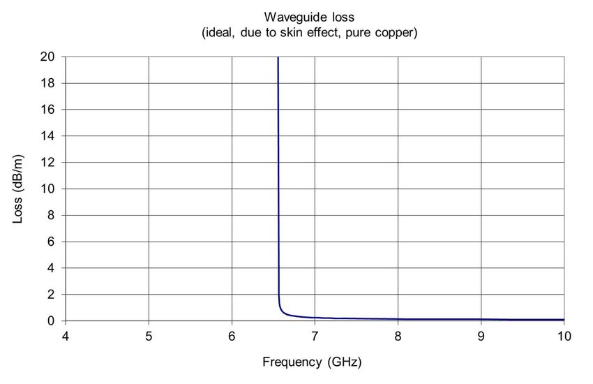
The radars covered by the present document use WR90/WG16 waveguides to transfer power between the transmitter
and the antenna and the waveguide cut-off frequency is 6 556 MHz. Therefore, measurements below this frequency do
not provide valid results since the waveguide is unable to support power transfer along its length below the cut-off
frequency.
4.2.1.6.3 Conformance
The conformance tests are specified in clause 5.3.1.6.
The results obtained shall not exceed the limits specified in clause 4.2.1.6.2.
4.2.2 Receiver Requirements
4.2.2.1 Noise Figure
4.2.2.1.1 Definition
The receiver noise figure measures the degradation of the signal-to-noise ratio, caused by components in the radio-
frequency signal chain.
4.2.2.1.2 Limits
The receiver noise figure shall not exceed 6 dB.
4.2.2.1.3 Conformance
The conformance test is specified in clause 5.3.2.1.
The results obtained shall not exceed the limits specified in clause 4.2.2.1.2.
4.2.2.2 Receiver Selectivity
4.2.2.2.1 Definition
The receiver selectivity is the ability of a receiver to detect and decode a desired signal in the presence of an unwanted
interfering signal outside the B-40 bandwidth.
NOTE: Signals inside the B-40 bandwidth are not considered as interfering signals because they fall into the
desired frequency range for the reception of wanted signals.
4.2.2.2.2 Limits
The receiver selectivity of the radar shall correspond to the requirements shown in Figure 4. The maximum power level
of the unwanted signal, measured at the output of the digital signal processing as shown in Figure E.1, shall be no more
than 12 dB plus LNFE gain above the calculated MDS level.
EXAMPLE 1: If the calculated MDS of the radar system is -102 dBm and the LNFE gain is 20 dB, then the
maximum level of unwanted signals at the output of the digital signal processing is -70 dBm.
ETSI17 Final draft ETSI EN 303 347-3 V1.1.5 (2021-03)
NOTE 1: All LNFE input signals are increased by its gain, keeping the relation between wanted and unwanted
signal levels.
For radars with an asymmetrical spectrum, the calculated B-40 bandwidth can be offset from the operating frequency.
The operating frequency shall be kept inside the calculated B-40 bandwidth.
The receiver selectivity shall be at least verified in the range of:
- Lower B-40 to (Lower B-40 - 500 MHz)
- Upper B-40 to (Upper B-40 + 500 MHz)
The B-40 bandwidth shall be excluded from the receiver selectivity measurement.
EXAMPLE 2: If the meteorological radar operates at 9 375 MHz and the B-40 is equal to 20 MHz, then the lower
frequency limit of the disturbing signal is 8 865 MHz. The upper limit is equal to 9 885 MHz.
The swept frequency shall encompass all image frequencies present in the receiver design. If the image frequencies are
not covered by the verified frequency range as defined above the range shall be extended to cover the image frequencies
accordingly.
The image frequency can be calculated as:
= + 2× ,
−2× ,
>
<
(1)
The measurement of the receiver selectivity shall be done at the output of the digital signal processing as shown in
Figure E.1.
In order to determine if the receiver selectivity follows the required selectivity mask, a disturbance signal level at the
MDS level plus the required attenuation shall be applied. The minimum input level is the MDS level and is calculated
by the following formula:
= −174 + + (2)
Where:
• -174 dBm is the noise power value in dBm, measured with 1 Hz bandwidth (BN) at 290° Kelvin and derived
from the available noise power Ni on the receiver input. = × × . Where:
Boltzmann constant = 1,38064852 × 10 .
- k
- T0 Temperature in Kelvin.
• NF(dB) is the receiver noise figure in dB. Measurement of the noise figure is described in clause 5.3.2.1.
• BW(dB) is the matched filter bandwidth in dB. Calculated as: 10 log () .
NOTE 2: The matched filter bandwidth usually corresponds to the transmitted pulse length and is usually the
inverse of the pulse length. For example, a 0,8 µs pulse length results in a 1,25 MHz matched filter
bandwidth.
The applied power level at the lower and upper B-40 frequency shall be the MDS level + 40 dB as shown in Figure 4.
The receiver selectivity mask shall be as shown in Table 4. The input power of the receiver shall not exceed -30 dBm.
ETSI18 Final draft ETSI EN 303 347-3 V1.1.5 (2021-03)
Table 4: Receiver selectivity mask
Frequency offset relative to Maximum interfering power level Slope
fc by multiple of the dB above MDS dB/decade
B-40 bandwidth
0 to 0,5 None 0
0,5 40 -∞
0,5 to 5 +40 to 70 or -30 dBm -30
5 to 10,8 70 to 90 or -30 dBm -60
10,8 to ∞ -30 dBm 0
Power
disturbing signal disturbing signal
Max. Level
-30 dBm
40 dB
MDS Level
B-40
fc Frequency
Figure 4: Resulting receiver selectivity mask (not to scale) -
The maximum disturbance level was set to -30 dBm
4.2.2.2.3 Conformance
The conformance tests are specified in clause 5.3.2.2.
The results obtained shall not exceed the limits specified in clause 4.2.2.2.2.
4.2.2.3 Receiver Compression Level
4.2.2.3.1 Definition
The compression level is defined as when one of the receiver stages becomes nonlinear thereby causing distortion and
other non-linear effects that prevents proper operation of the receiver.
The receiver input compression level is defined as when the receiver output is 1 dB into compression as can be seen in
Figure 5.
The compression level shall be measured at the nominal receiver frequency which is used to detect the desired signal
generated by the transmitter.
ETSI19 Final draft ETSI EN 303 347-3 V1.1.5 (2021-03)
Figure 5: Illustration of finding the LNA input 1 dB compression point
4.2.2.3.2 Limits
The input of the radar shall be able to handle signal levels up to at least -35 dBm without being in compression.
NOTE 1: A high compression level corresponds to high immunity against blocking. Blocking is the effect when a
strong Out-of-Band or spurious signal degrades the receiver ability to detect the wanted signal.
NOTE 2: Outside the B-40 bandwidth the maximum disturbance level is -30 dBm as stated in clause 4.2.2.2.2.
The measurement of the saturation signal shall be done at the output of the digital signal processing as shown in
Figure E.1.
4.2.2.3.3 Conformance
The conformance tests are specified in clause 5.3.2.3.
The results obtained shall not exceed the limits specified in clause 4.2.2.3.2.
5 Testing for compliance with technical requirements
5.1 General requirements
All operating modes and product configurations shall be in compliance with the technical requirements in the present
document.
ETSI20 Final draft ETSI EN 303 347-3 V1.1.5 (2021-03)
Tests defined in the present document shall be carried out at representative points within the boundary limits of the
operational environmental profile defined by its intended use.
Where technical performance varies subject to environmental conditions, tests shall be carried out under a sufficient
variety of environmental conditions (within the boundary limits of the operational environmental profile defined by its
intended use) to give confidence of compliance for the affected technical requirements.
5.2 Environmental conditions for testing
5.2.1 Test Conditions
Unless otherwise stated, all tests shall take place under the following normal test conditions.
5.2.2 Normal temperature and humidity
The normal temperature and humidity conditions for tests typically are a combination of temperature and humidity and
shall be within the following ranges:
a) temperature: +15 °C to +35 °C.
b) relative humidity: not exceeding 75 %.
5.2.3 Normal test power supply
The test voltage for the equipment to be connected to an AC supply shall be the nominal mains voltage declared by the
manufacturer including a variation of ±10 %. For the purpose of the present document, the nominal voltage shall be the
declared voltage or each of the declared voltages for which the equipment is indicated as having been designed. The
frequency of the test voltage shall be 50 Hz ± 1 Hz.
5.3 Radio test suites
5.3.1 Transmitter test specification
5.3.1.1 Frequency Tolerance
The antenna shall be replaced by a dummy load. The forward port of the system coupler shall be used If a reverse port
is available on the system coupler, it shall be terminated with a 50 Ω termination.
To measure the frequency tolerance a spectrum analyser shall be used. An additional attenuator shall be used if needed
in order to protect the spectrum analyser input from the high power RF pulses. The measurement setup from Annex C
shall be used.
The frequency measurements shall be performed with all available pulse length settings. The corresponding PRF shall
be chosen in order to get the maximum possible duty cycle for each pulse length. After the frequencies for the
maximum duty cycles are measured, the measurements shall be repeated with the lowest duty cycle. The lowest duty
cycle is defined as the combination of shortest pulse length and lowest PRF. The lowest PRF shall be the one, which
will be generally used in meteorological radar systems during normal operation.
NOTE: A typical lower value for the PRF is 250 Hz as mentioned in Recommendation ITU-R M.1849-1 [i.3].
ETSI21 Final draft ETSI EN 303 347-3 V1.1.5 (2021-03)
Between each measurement, a waiting period shall be observed, so as to achieve thermal stability. Thermal stability is
achieved if the temperature of the final RF power amplifier (klystron or solid state amplifier) or power oscillator
(magnetron) does not change by more than 2 K per minute. The waiting period shall be at least 20 min. During this
time, the transmitter shall be in operation and transmitting with the new pulse length and PRF values.
A spectrum analyser shall be used to display the frequency spectrum in order to obtain the centre between the highest
and lowest frequencies.
When measuring the frequency tolerance for radars with a phase or frequency modulated pulse the tolerance is
measured on the frequency reference(s) used for generating the radar output signal. If frequency multiplication in the
process of generating the output signal is used, then the frequency tolerance shall be divided by the used multiplication
factor.
5.3.1.2 Transmitter Power
The antenna shall be replaced by a dummy load. If the meteorological radar system is equipped with dual polarization
capability, the single polarization mode shall be activated and shall be used for the measurements. If only permanent
dual polarization mode is available and no coupler in front of the power divider is available, the coupling ratio from the
power divider shall be added to the power measurement. The forward port of the system coupler shall be used. If a
reverse port is available on the system coupler, it shall be terminated with a 50 Ω termination. The measurement setup
from Annex C shall be used.
The transmitter power of a pulse radar is the peak value of the transmitter pulse power during the transmission pulse
(PEP).
If the transmitter power varies over the azimuth or elevation movement of the antenna, the highest PEP value measured
during a period equal to at least one azimuth rotation period and between the lowest and highest elevation shall be used.
The transmitter power measurements shall be performed with all available pulse length settings. The corresponding
PRF shall be chosen in order to get the same duty cycle for each pulse length setting.
To determine the PEP of the pulse a peak power meter with direct reading of the transmitter pulse power shall be used.
The PEP shall be measured at the 50 % point of the pulse length. If the transmitter pulse is rippled the average over the
pulse shall be used as can be seen in Figure 6.
Power Power
Peak Power
Peak Power
Time Time
0% 50 % 100 % 0% 50 % 100 %
Figure 6: Transmitter output power
To reference the indicated transmitter power to the transmitter output flange the coupling factor of the system coupler
shall be added to the power measurement. If an additional attenuator or RF cable has been inserted between the system
coupler forward port and the power meter this shall be added to the power measurement. If the power meter does not
allow for compensation of the coupling loss and additional attenuator, then the coupling loss and attenuator value shall
be added to the meter reading.
5.3.1.3 Measured B-40 Bandwidth
The measurements of the -40 dB bandwidth shall be performed with the same settings as in clause 5.3.1.4.
The bandwidth of the emissions 40 dB below PEP shall be measured. Measurement setup shall be as described in
Annex D.
ETSI22 Final draft ETSI EN 303 347-3 V1.1.5 (2021-03)
5.3.1.4 Out-of-Band emissions
For meteorological radar systems with multiple pulse length, the B-40 bandwidth shall be calculated for each individual
used pulse length as described in Annex B and the maximum B-40 bandwidth obtained shall be used to establish the
shape of the emission mask. An example of the mask can be seen in Figure 7.
The receiver shall be replaced by a dummy load. If the meteorological radar system is equipped with dual polarization
capability, the single polarization mode shall be activated and shall be used for the measurements. If only permanent
dual polarization mode is available and no coupler in front of the power divider is available, the coupling ratio from the
power divider shall be added to the measurement. The forward port of the system coupler shall be used. If a reverse port
is available on the system coupler, it shall be terminated with a 50 Ω termination.
The so-called indirect method specified in Annex 1 of Recommendation ITU-R M.1177-4 [3] shall be applied for the
measurement of unwanted emissions of radar systems. The transmitter output spectrum shall be measured at the system
coupler of the transmitter as illustrated in Annex D.
A margin of at least 10 dB between the Out-of-Band emission mask and the noise floor measurement device shall be
achieved.
NOTE 1: Further information how to perform the measurement can be found in Recommendation ITU-R
M.1177-4 [3].
The OoB power emission shall be measured in the frequency bands given in Table 5 or Table 6 depending on the PEP.
If the PEP is greater than 150 kW the Table 5 shall be used and for powers equal to or less than 150 kW the Table 6
shall be used.
Table 5: OoB emission boundaries for -90 dBpp
Lower OoB boundary Upper OoB boundary
Carrier frequency - 10,8 × B-40 Carrier frequency + 10,8 × B-40
NOTE: The values are taken from Table 1 in ECC/Recommendation (02)05 [2].
Table 6: OoB emission boundaries for -100 dBpp
Lower OoB boundary Upper OoB boundary
Carrier frequency - 15,8 × B-40 Carrier frequency + 15,8 × B-40
NOTE: The values are taken from Table 1 in ECC/Recommendation (02)05 [2].
EXAMPLE: Typical meteorological radar system parameters are e.g. a centre frequency of 9 375 MHz,
transmitter power of 80 kW, a pulse duration of t = 500 ns and a rise time of tr = 100 ns. The
40 dB bandwidth calculated applying the equation from Annex B is 34 MHz. This leads to OoB
boundaries at 15,8 × 34 MHz = 537,2 MHz away from the operating frequency. For this example
the absolute boundaries between OoB emissions and spurious emissions are:
9 375 MHz - 537,2 MHz = 8 837,8 MHz and 9 375 MHz + 543,5 MHz = 9 912,2 MHz
(see Figure 7).
Figure 7 shows the calculated emission masks for the aforementioned parameters of a typical
meteorological radar system applying the mask specification in Annex B which is corresponding
to the dashed line in Figure A2.1b of ECC/Recommendation (02)05 [2].
ETSI23 Final draft ETSI EN 303 347-3 V1.1.5 (2021-03)
8 837 MHz 9 375 MHz 9 912 MHz
Lower OoB boundary assigned frequency Upper OoB boundary
10
0
-10
-20
-30
-40
]
B -50
d
[
p
p -60
B
d
-70
-80
-90
-100
-110
-120
8675 8875 9075 9275 9475 9675 9875 10075
Frequency [MHz]
Figure 7: Example of a calculated emissions mask for pulse duration t = 500 ns and
rise time tr = 100 ns at centre frequency of 9 375 MHz
For the measurements below 12 400 GHz, a WR90/WG16 waveguide shall be used as indicated in Table 7, the lower
measurement frequency shall be equal to the cut-off frequency, i.e. 6 556 MHz while the upper boundary is defined in
Table 1 of ERC/Recommendation 74-01 [1] (see Table 8).
NOTE 2: The radars covered by the present document use WR90/WG16 waveguides to transfer power between the
transmitter and the antenna and the waveguide cut-off frequency is 6 556 MHz as shown in Table 7.
Therefore, measurements below this frequency do not provide valid results since the waveguide is unable
to support power transfer along its length below the cut-off frequency.
All measurements of Out-of-Band emissions shall be made with a measurement bandwidth equal to the reference
bandwidth of 1 MHz according to Annex 2 of Recommendation ITU-R M.1177-4 [3].
5.3.1.5 Spurious emissions
For the spurious emission measurements the so-called indirect method specified in clause 6.4.3 of Annex 1 of
Recommendation ITU-R M.1177-4 [3] shall be used. To perform the measurements, the radar system and the measuring
equipment shall be set up as displayed in Annex D. The spurious power emissions shall be measured in the frequency
ranges outside the OoB emissions boundaries.
ETSIYou can also read