Opto-Electronic Oscillators for Micro- and Millimeter Wave Signal Generation - MDPI
←
→
Page content transcription
If your browser does not render page correctly, please read the page content below
electronics
Review
Opto-Electronic Oscillators for Micro- and Millimeter Wave
Signal Generation
Mehmet Alp Ilgaz * and Bostjan Batagelj

                                          Faculty of Electrical Engineering, University of Ljubljana, 1000 Ljubljana, Slovenia; bostjan.batagelj@fe.uni-lj.si
                                          * Correspondence: mehmet.ilgaz@fe.uni-lj.si

                                          Abstract: High-frequency signal oscillators are devices needed for a variety of scientific disciplines.
                                          One of their fundamental requirements is low phase noise in the micro- and millimeter wave ranges.
                                          The opto-electronic oscillator (OEO) is a good candidate for this, as it is capable of generating a signal
                                          with very low phase noise in the micro- and millimeter wave ranges. The OEO consists of an optical
                                          resonator with electrical feedback components. The optical components form a delay line, which
                                          has the advantage that the phase noise is independent of the oscillator’s frequency. Furthermore, by
                                          using a long delay line, the phase noise characteristics of the oscillator are improved. This makes it
                                          possible to widen the range of possible OEO applications. In this paper we have reviewed the state
                                          of the art for OEOs and micro- and millimeter wave signal generation as well as new developments
                                          for OEOs and the use of OEOs in a variety of applications. In addition, a possible implementation
                                          of a centralized OEO signal distribution as a local oscillator for a 5G radio access network (RAN)
                                          is demonstrated.

                                          Keywords: opto-electronic oscillator; phase noise; microwave signal; millimeter wave signal; 5G

                                   radio access network; long-term stability; multimode operation; wideband OEO; integrated OEO

Citation: Ilgaz, M.A.; Batagelj, B.
Opto-Electronic Oscillators for Micro-
and Millimeter Wave Signal
                                          1. Introduction
Generation. Electronics 2021, 10, 857.
https://doi.org/10.3390/                       High-precision signal oscillators are needed in a variety of fields such as satellite
electronics10070857                       communications, optical communications, radar applications, radio-over-fiber communica-
                                          tions, etc. [1]. In its most basic form, an oscillator consists of a resonator and a feedback
Academic Editor: Geok Ing Ng              component. When the Barkhausen conditions are satisfied, the oscillator starts generating
                                          the fundamental oscillation signal. An opto-electronic oscillator (OEO) is one of the most
Received: 3 March 2021                    popular types of oscillators for generating micro- and millimeter wave signals [2,3]. The
Accepted: 1 April 2021                    OEO has a number of optical components such as a laser diode [4,5], an optical fiber [6]
Published: 3 April 2021                   and a photodiode [7]. The electrical components including an electrical bandpass filter and
                                          an electrical amplifier are used to complete the feedback loop. The laser of the OEO can be
Publisher’s Note: MDPI stays neutral      modulated directly, or it can use external modulation with an electro-optic modulator such
with regard to jurisdictional claims in   as a Mach Zehnder modulator (MZM) [8] or an electro-absorption modulator [9]. A typical
published maps and institutional affil-
                                          externally modulated OEO is shown in Figure 1.
iations.
                                               Currently, −163 dBc/Hz at a 6 kHz offset from the carrier for an operating frequency
                                          of 10 GHz [10] is the lowest phase noise achieved so far. Different types of configurations
                                          for the OEO have already been presented in the literature. The dual-loop and multi-loop
                                          configurations [11–14], coupled OEO [15–18], injection-locked OEO [19–22], OEO with
Copyright: © 2021 by the authors.         quality multiplier [23], and OEO with feedback loop [24] are some of the well-known
Licensee MDPI, Basel, Switzerland.        configurations. Moreover, optical solutions are possible by adding components such as
This article is an open access article    optical filters [25–27] and optical amplifiers [28,29] or by adjusting the optical link to
distributed under the terms and
                                          achieve an optical gain [30]. These are already used to improve the stabilization of the
conditions of the Creative Commons
                                          OEO. Since an OEO consisting of such bulky components is very large, some methods
Attribution (CC BY) license (https://
                                          to reduce the size of the oscillator device have already been reported. There are several
creativecommons.org/licenses/by/
                                          solutions such as using a whispering-gallery-mode resonator (WGMR) [31–34], a ring
4.0/).

Electronics 2021, 10, 857. https://doi.org/10.3390/electronics10070857                                        https://www.mdpi.com/journal/electronics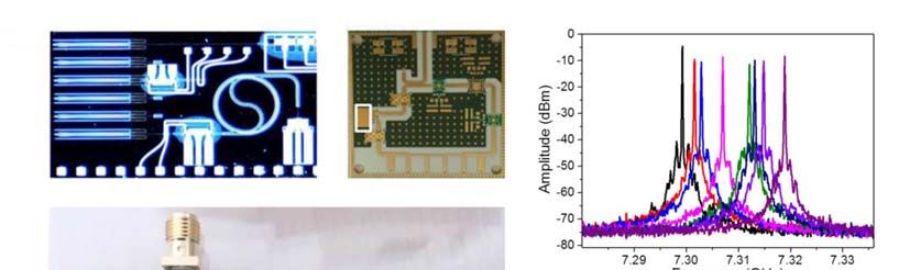
Electronics 2021, 10, x FOR PEER REVIEW 2 of 19
Electronics 2021, 10, 857 2 of 19
as using a whispering-gallery-mode resonator (WGMR) [31–34], a ring resonator [35,36],
or an electro-absorption
resonator modulated lasermodulated
[35,36], or an electro-absorption [37] that decrease
laser [37]the size
that of the OEO.
decrease In 2017,
the size of the a
OEO.
fully In 2017, a fully
integrated OEOintegrated OEOin
was reported wasthereported
literature inby
theJ.literature
Tang et al.by[38,39].
J. Tang In
et al. [38,39].a
addition,
Intheoretical
addition, aand
theoretical and experimental
experimental study of thestudy of the characteristics
characteristics of an injection-locked
of an injection-locked OEO was
OEO was presented
presented and published
and published in severalinjournals
several[40–44].
journalsRecently,
[40–44]. Recently,
a W-bandaOEO W-band wasOEOintro-
was introduced
duced by G.K.M. byHasanuzzaman
G.K.M. Hasanuzzaman
et al. [45].etThe
al. OEO
[45]. provided
The OEO aprovided a phase
phase noise noise
characteris-
characteristic of −101
tic of −101 dBc/Hz atdBc/Hz
a 10 kHz at offset
a 10 kHz
from offset fromGHz
the 94.5 the 94.5 GHzOn
carrier. carrier. On the
the other other
hand, an
hand, an opto-electronic parametric oscillator [46] was
opto-electronic parametric oscillator [46] was reported in 2020. reported in 2020.
Figure1.1.Single-loop
Figure Single-loopopto-electronic
opto-electronicoscillator
oscillator(OEO)
(OEO)with
withelectrical
electricalcomponents.
components.
There are some more recent developments in the use of OEOs in various applications.
There are some more recent developments in the use of OEOs in various applications.
One example of this is terahertz (THz) photonic signal generation using an OEO [47–49].
One example of this is terahertz (THz) photonic signal generation using an OEO [47–49].
Another possible application of an OEO is to use it as a local oscillator (LO) in the central
Another possible application of an OEO is to use it as a local oscillator (LO) in the central
office of a 5G radio access network (RAN) [50–52]. The single-loop OEO can be combined
office of a 5G radio access network (RAN) [50–52]. The single-loop OEO can be combined
with an optical fiber path selector to measure the free spectral range (FSR) and side-mode
with an optical fiber path selector to measure the free spectral range (FSR) and side-mode
suppression ratio (SMSR) of the OEO for different lengths of the optical delay line [53].
suppression ratio (SMSR) of the OEO for different lengths of the optical delay line [53].
There are other applications of OEOs such as an acoustic sensor [54], low-power radio
There are other applications of OEOs such as an acoustic sensor [54], low-power radio
frequency (RF) signal detection [55], phase-locked loops [56–58], parity time-symmetric
frequency (RF) signal detection [55], phase-locked loops [56–58], parity time-symmetric
OEO [59,60], silicon micro-ring-based OEO [61] and linear frequency-modulated waveform
OEO [59,60], silicon micro-ring-based OEO [61] and linear frequency-modulated wave-
generation [62], etc.
form generation [62], etc.
Long-term stability and side modes (multimode operation) are the main challenges
Long-term
affecting stabilityofand
the stabilization side modes
an OEO. The OEO (multimode operation)
uses an optical fiber thatareisthe mainaffected
mainly challenges
by
affecting the stabilization of an OEO. The OEO uses an optical fiber
the temperature variations in the environment. This leads to fluctuations in the oscillation that is mainly affected
by the temperature
frequency over time, variations in the environment.
which is referred to as the frequencyThis leads to fluctuations
drift (in other words,in the oscil-
long-term
lation frequency
stability). On the over
othertime,
hand,which is referred
electrical bandpass to as the frequency
filters have bandwidth drift (inlimitations
other words, in
long-term stability). On the other hand, electrical bandpass filters
the micro- and millimeter wave ranges. Electric bandpass filters are used in the oscillator have bandwidth limita-
tionstoindestroy
loop the micro- and modes
the side millimeterin the wave ranges. Electric
RF spectrum bandpassthe
and determine filters
main are usedofinthe
mode the
oscillator loop to destroy the side modes in the RF spectrum and determine
oscillation. Due to the bandwidth limitation of the filter, the side modes are not completely the main mode
of the oscillation.
filtered out, and they Duecan to therefore
the bandwidth be seen limitation
in the RFofspectrum.
the filter, Thethe side
ratiomodes
between arethe
not
completely filtered
fundamental mode and out,the
and they can
spurious sidetherefore
modes be seen inSMSR.
is called the RF spectrum. The ratio be-
tweenThethe fundamental
short-term mode
stability andphase
(i.e., the spurious
noise) isside
mainlymodesbasedis called
on theSMSR.
length of the delay
The short-term stability (i.e., phase noise) is mainly
line of the OEO. The OEO can use a long delay line to achieve the lowest based on the length of thephase
possible delay
line of the OEO. The OEO can use a long delay line to achieve
noise. However, using a long delay line boosts the power of the side modes because the the lowest possible phase
noise.
FSR However,
becomes lower, using a long
and the sidedelay
modes line
areboosts the power
more difficult of the
to filter outside
duemodes because the
to the bandwidth
FSR becomes
limitation of thelower, andfilter.
electrical the side modes are
For instance, themore
use of difficult
a 1-kmto filter
fiber hasoutan due
FSR to
of the
200 band-
kHz,
widtha limitation
while 15 km fiber of has
the an
electrical
FSR offilter. For instance,
13.4 kHz. the use ofbetween
The relationship a 1-km fiberSMSR hasandanphase
FSR of
200 kHz,
noise while a 15
performance ofkm
thefiber
OEOhas an FSR ofoptical
at different 13.4 kHz. The is
lengths relationship
shown in Figure between 2. SMSR and
phase noise performance of the OEO at different optical lengths is shown in Figure 2.
Electronics 2021, 10,
Electronics 2021, 10, 857
x FOR PEER REVIEW 33 of
of 19
19
Figure 2. Comparison of phase noise
noise and
and side-mode
side-mode suppression
suppressionratio
ratio(SMSR)
(SMSR)performance
performanceofofOEO
with
OEO 1with
km 1and
km 15
andkm
15 delay line line
km delay length [1]. [1].
length Reprinted with
Reprinted permission
with permissionfrom
fromref.
ref.[1].
[1].Copyright
Copy-
right 2015 IEEE.
2015 IEEE.
As can
can be
beseen
seenfrom
fromthe theexperimental
experimentalresults
resultsinin
Figure
Figure 2, there
2, thereis aistradeoff between
a tradeoff betweenthe
short-term
the stability
short-term and and
stability multimode
multimodeoperation of theofOEO.
operation The 1The
the OEO. km OEO1 km has OEO about a 30 dBa
has about
improvement
30 dB improvementperformance in the SMSR,
performance in thebut the 15
SMSR, km
but OEO
the has OEO
15 km a significant improvement
has a significant im-
in phase noise, which is about 20 dB at 1 kHz and 10 kHz offsets
provement in phase noise, which is about 20 dB at 1 kHz and 10 kHz offsets from the from the carrier.
In this paper, recent advances in OEO configurations are presented, using new re-
carrier.
sultsInto this
improve
paper,the stability
recent of short-term,
advances in OEO long-term
configurationsand multimode
are presented, operation.
using newIt also
re-
highlights
sults new areas
to improve the of science,oftechnology
stability short-term, and engineering
long-term andwhere
multimodethe OEO can be applied.
operation. It also
highlights new areas of science, technology and engineering where the OEO can be ap-
2. Current Progress of the Common Topologies of the OEO
plied.
In this section, the paper focuses on recent advances in the development of OEOs
and the
2. Current main challenges
Progress of thethat they face:
Common multimode
Topologies operation,
of the OEO as well as short-term and
long-term stability. In the first subsection, the paper focuses on multimode operation and
In this section, the paper focuses on recent advances in the development of OEOs
short-term stability, with long-term stability following this subsection.
and the main challenges that they face: multimode operation, as well as short-term and
long-term
2.1. Progressstability.
of the OEOIn the first Lower
toward subsection,
SMSRthe andpaper
Phasefocuses
Noise on multimode operation and
short-term stability, with long-term stability following this subsection.
As mentioned earlier, one of the general challenges associated with OEO design is
multimode operation. Since an electrical bandpass filter has bandwidth limitations, some
2.1. Progress of the OEO Toward Lower SMSR and Phase Noise
optical solutions have been proposed. One of the most popular solutions is to form more
than Asonementioned
optical delay earlier,
line. one
These of dual
the general challenges
or multi-loop OEOsassociated
have seenwith OEO design
widespread use for is
multimode
more than 20 operation.
years to Since an electrical
eliminate multimode bandpass filter[63].
operation has bandwidth
The typicallimitations,
configuration some of
optical solutions
a dual-loop OEOhave is shownbeen in proposed.
Figure 3.One of the
In this most popularone
configuration, solutions
loop isisusedto form
as a more
long
than one optical delay line. These dual or multi-loop OEOs have
cavity, while the other behaves as a short cavity. This is achieved by using short and seen widespread use for
long
more
fibers than 20 yearsloops.
in different to eliminate
One ofmultimode operation in
the recent advances [63].
theThe typical OEO
dual-loop configuration
is the useofofa
dual-loop OEO is
multicore fibers andshown in Figure 3. In this configuration,
the self-polarization-stabilization one loop
technique [64].isConventionally,
used as a long cav-two
ity, while
or more the other behaves
single-mode as a short
fibers (SMFs) are usedcavity. Thisaisdual-
to form achieved by usingconfiguration.
or multi-loop short and long In
fibers in different
this novel approach, loops. One of the recent
the combination of coresadvances in the dual-loop
in a multicore fiber is used OEO is theause
to form shortof
multicore
and a longfibers
cavityand[64].the self-polarization-stabilization
With this novel approach, an SMSR technique
of 61 dB [64].
wasConventionally,
achieved for a
two or moreOEO
microwave single-mode
oscillatingfibersat 7.8(SMFs) are usedrecent
GHz. Another to form a dual-isorparity
approach multi-loop
symmetryconfigura-
of the
tion.
OEO In thisa novel
with approach,
dual-loop the combination
configuration [65]. Theof coressymmetry
parity in a multicore fiber is by
is achieved used to form
using two
aoptical
short carriers
and a long with different
cavity [64]. optical
With this powers.
novel Parity
approach,symmetry
an SMSR provides
of 61 dB additional gain
was achieved
for athe main mode.
microwave OEO With the combination
oscillating at 7.8 GHz. of parity
Another symmetry and a dual
recent approach loop, asymmetry
is parity 60.71 dB
SMSR
of was achieved
the OEO for a 10 configuration
with a dual-loop GHz central frequency.
[65]. The parity symmetry is achieved by using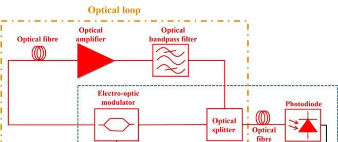
Electronics 2021,10,
Electronics2021, 10,857
x FOR PEER REVIEW 44of
of19
19
Figure 3. Typical
Figure 3. Typical dual-loop
dual-loop configuration
configurationof
ofan
anOEO.
OEO.
An
An injection-locked
injection-locked OEO OEO is is another
another configuration
configuration to to improve
improve the
the SMSR
SMSR performance
performance
of
of the
the OEO.
OEO. It It was
was first
first proposed
proposed in in 2005
2005 [63,66]. The typical
[63,66]. The typical configuration
configuration ofof an injection-
an injection-
locked
locked OEO is shown in Figure 4. In the typical configuration of the OEO, it consists of
OEO is shown in Figure 4. In the typical configuration of the OEO, it consists of
two
two oscillator
oscillator blocks.
blocks. One
One of of them
them is is classified
classified asas the
the master
master OEO
OEO and
and other
other as as the
the slave
slave
OEO
OEO [63].
[63]. This
This approach
approach is is used
used toto suppress
suppress thethe spurious
spurious side
side modes
modesand andat
at the
the same
same time
time
maintain the quality factor (Q-factor) of the OEO [63]. The slave OEO is
maintain the quality factor (Q-factor) of the OEO [63]. The slave OEO is used to suppressused to suppress the
spurious side modes as it employs a short fiber, while the master OEO
the spurious side modes as it employs a short fiber, while the master OEO employs a long employs a long fiber
to keep
fiber to the
keephigh
theQ-factor. In reference
high Q-factor. [67], a tunable,
In reference [67], a dual-loop, injection-locked
tunable, dual-loop, OEO was
injection-locked
presented. The OEO was tunable from 11.1 GHz to 12.1 GHz, and
OEO was presented. The OEO was tunable from 11.1 GHz to 12.1 GHz, and the spurious the spurious side modes
were suppressed below − 115 dBc/Hz [67]. Another approach
side modes were suppressed below −115 dBc/Hz [67]. Another approach was to form awas to form a microwave
frequency divider based on the injection-locked OEO [68]. In this implementation, the
microwave frequency divider based on the injection-locked OEO [68]. In this implemen-
10 GHz free-running OEO was injected with a 20 GHz microwave signal. A single-sideband
tation, the 10 GHz free-running OEO was injected with a 20 GHz microwave signal. A
(SSB) phase noise of −130 dBc/Hz at a 10 kHz offset was achieved. In Reference [69], an
single-sideband (SSB) phase noise of −130 dBc/Hz at a 10 kHz offset was achieved. In Ref-
injection-locked OEO based on stimulated Brillouin scattering (SBS) is described. This
erence [69], an injection-locked OEO based on stimulated Brillouin scattering (SBS) is de-
approach provided a frequency tunability up to 40 GHz with an SMSR of 60 dB and an SSB
scribed. This approach provided a frequency tunability up to 40 GHz with an SMSR of 60
noise of −116 dBc/Hz at a 10 Hz offset.
dB and an SSB noise of −116 dBc/Hz at a 10 Hz offset.
The coupled OEO, introduced in 1997 [63,70], is another type of commonly used OEO
configuration to improve SMSR. In this configuration, the OEO consists of an optical loop
and an opto-electronic loop coupled via an electro-optic modulator [63]. The coupled OEO
is used to improve the phase noise characteristics and the SMSR. The typical configuration
of a coupled OEO is shown in Figure 5. An example of a recent development in the
coupled OEO was the synthesis of a 90 GHz signal using a 30 GHz coupled OEO [71]. The
90 GHz signal was obtained by biasing the MZM to the third harmonic. An SSB phase
noise of −104 dBc/Hz at a 1 kHz offset from the 90 GHz carrier was achieved in this
configuration [71]. On the other hand, a novel, coupled OEO with an erbium-doped fiber
(EDF) has been proposed [72]. The novel configuration allows a large spatial hole burning
(SHB) using the unpumped EDF to improve the SMSR and the phase noise. An SMSR of
more than 72.5 dB was achieved wherein the SSB phase noise was −123.6 dBc/Hz at a
10 kHz offset from the 10 GHz carrier signal.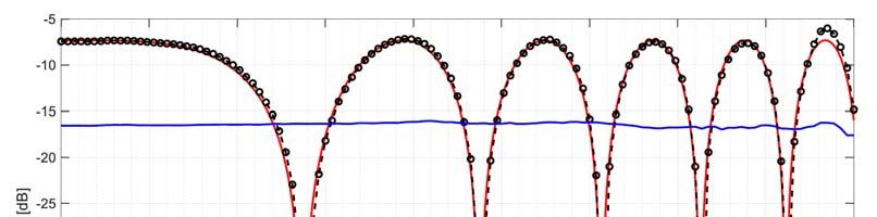
Electronics 2021, 10, 857 5 of 19
Electronics 2021, 10, x FOR PEER REVIEW 5 of 19
Electronics 2021, 10, x FOR PEER REVIEW 6 of 19
Figure4.4.Typical
Figure Typicalinjection-locked OEO.
injection-locked OEO.
The coupled OEO, introduced in 1997 [63,70], is another type of commonly used OEO
configuration to improve SMSR. In this configuration, the OEO consists of an optical loop
and an opto-electronic loop coupled via an electro-optic modulator [63]. The coupled OEO
is used to improve the phase noise characteristics and the SMSR. The typical configuration
of a coupled OEO is shown in Figure 5. An example of a recent development in the cou-
pled OEO was the synthesis of a 90 GHz signal using a 30 GHz coupled OEO [71]. The 90
GHz signal was obtained by biasing the MZM to the third harmonic. An SSB phase noise
of −104 dBc/Hz at a 1 kHz offset from the 90 GHz carrier was achieved in this configura-
tion [71]. On the other hand, a novel, coupled OEO with an erbium-doped fiber (EDF) has
been proposed [72]. The novel configuration allows a large spatial hole burning (SHB)
using the unpumped EDF to improve the SMSR and the phase noise. An SMSR of more
than 72.5 dB was achieved wherein the SSB phase noise was −123.6 dBc/Hz at a 10 kHz
offset from the 10 GHz carrier signal.
In addition to the typical solutions listed above, there are other novel solutions to
improve the phase noise and/or the SMSR characteristics of the OEO. For a millimeter-
wave OEO, a high-quality opto-electronic filter was proposed, e.g., a Q-factor of 30,000 at
a central frequency of 29.99 GHz [73]. This resulted in an 83 dB SMSR and a −113 dBc/Hz
SSB phase noise at a 10 kHz offset. A cascaded microwave filter was presented in [49]. In
this configuration, the cascaded filter configuration was implemented with a single pass-
band filter having an opto-electronic filter. With this approach, an SMSR of 125 dB and an
SSB phase noise of −103 dBc/Hz for a 10 kHz offset at the 17.33 GHz carrier were achieved.
Figure5.5.Typical
Figure Typicalconfiguration ofofa acoupled
coupledOEO.
The linewidth ofconfiguration
the laser can affect the OEO.
phase-noise performance of the OEO. A narrow-
band microcavity laser with a physical side length ofthere
16 μm
areisother
usednovel
for the microwave
2.2. In addition
Progress to OEO
of the the typical
Towardsolutions listed
Better Long-Term above,
Stability solutions to
signal generation
improve the phase in the and/or
noise loop of the theSMSR
OEO [74]. An SSB phase
characteristics of thenoise
OEO.ofFor
−116 dBc/Hz was
a millimeter-
Long-term
achieved a 10stability is another
from theimportant characteristic of themicrowave
OEO. Thesignalelectrical
wave OEO,for kHz offset
a high-quality opto-electronic carrier
filtermicrowave
was proposed,signal.
e.g.,The
a Q-factor of 30,000 atcan
a
bandpass
be tuned filter
between and the
1.85 optical
GHz and fiber are
10.24 GHzmajor components
thanks to a of
tunable the OEO
optical that are
bandpass tempera-
filter.
central frequency of 29.99 GHz [73]. This resulted in an 83 dB SMSR and a −113 dBc/Hz
ture-dependent [75]. For the frequency drift of a non-temperature-stabilized OEO operat-
SSB phase noise at a 10 kHz offset. A cascaded microwave filter was presented in [49].
ing at a 10 GHz central frequency, 8 ppm/K was measured [75]. One of the useful ap-
In this configuration, the cascaded filter configuration was implemented with a single
proaches is the temperature stabilization of the optical fiber and the electrical bandpass
passband filter having an opto-electronic filter. With this approach, an SMSR of 125 dB
filter of the OEO loop [75]. With this solution, 0.1 ppm/K was achieved. In 2016, Luka
Bogataj et al. brought another approach, i.e., the OEO with a feedback control loop [24,76].
The configuration of the feedback control loop is shown in Figure 6.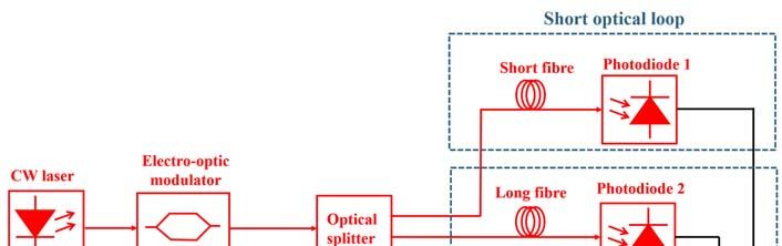
Electronics 2021, 10, 857 6 of 19
and an SSB phase noise of −103 dBc/Hz for a 10 kHz offset at the 17.33 GHz carrier
were achieved. The linewidth of the laser can affect the phase-noise performance of the
OEO. A narrowband microcavity laser with a physical side length of 16 µm is used for
the microwave signal generation in the loop of the OEO [74]. An SSB phase noise of
−116 dBc/Hz was achieved for a 10 kHz offset from the carrier microwave signal. The
microwave signal can be tuned between 1.85 GHz and 10.24 GHz thanks to a tunable
Figure bandpass
optical 5. Typical configuration
filter. of a coupled OEO.
2.2.Progress
2.2. ProgressofofthetheOEO
OEOtoward
Toward Better
Better Long-Term
Long-Term Stability
Stability
Long-termstability
Long-term stabilityisisanother
anotherimportant
importantcharacteristic
characteristicofofthe theOEO.
OEO.TheTheelectrical
electrical
bandpassfilter
bandpass filterand
and the
the optical
optical fiber
fiber areare major
major components
components of OEO
of the the OEO
that that are tempera-
are temperature-
ture-dependent
dependent [75]. For[75].
theFor the frequency
frequency drift ofdrift of a non-temperature-stabilized
a non-temperature-stabilized OEO operat-
OEO operating at a
10ing
GHz at acentral
10 GHz central 8frequency,
frequency, ppm/K was 8 ppm/K
measured was measured
[75]. One of the[75]. Oneapproaches
useful of the useful ap-
is the
proaches is stabilization
temperature the temperature stabilization
of the optical fiberofandthe the
optical fiber bandpass
electrical and the electrical bandpass
filter of the OEO
loop
filter[75]. With
of the OEOthis loop
solution,
[75].0.1 ppm/K
With this was achieved.
solution, In 2016,was
0.1 ppm/K Luka Bogataj et
achieved. Inal. brought
2016, Luka
another
Bogatajapproach,
et al. broughti.e., another
the OEOapproach,
with a feedback
i.e., thecontrol
OEO with loopa [24,76].
feedback The configuration
control of
loop [24,76].
the
Thefeedback controlofloop
configuration is shown in
the feedback Figure
control 6. is shown in Figure 6.
loop
Figure6.6.OEO
Figure OEOwith
withaafeedback-control
feedback-controlloop.
loop
InInthe
thefeedback
feedbackcontrol
controlloop,
loop,the
thefrequency
frequencydiscriminator
discriminatorcontrols
controlsthe
thetemperature
temperatureofof
the laser by measuring the refractive index of the optical fiber. A proportional–integral
the laser by measuring the refractive index of the optical fiber. A proportional–integral
(PI)
(PI)controller
controllerisisused
usedtotocontrol
controlthe
thetemperature
temperatureofofthe
thelaser.
laser.Using
Usingthe
thefeedback
feedbackcontrol
control
loop, a frequency drift of 0.05 ppm/K was achieved for a single-loop OEO operating at
3 GHz. In 2017, the optical delay stabilization system (ODSS) was introduced [77] for
active fiber delay stabilization at a different wavelength than used in the oscillator loop.
The outstanding result of a 0.02 ppm/K frequency drift was achieved for a 3 GHz OEO.
However, the frequency of the oscillator can be increased, but this does not affect the
stability result because the stabilization is performed at an independent wavelength.
Phase-locked loops (PLLs) are alternative solutions that are widely used in practice to
improve the long-term stability of the OEO signal. In this case, the OEO signal is locked by
the PLL signal [78]. The typical configuration of an OEO with a PLL is shown in Figure 7.
For an OEO with a PLL configuration, a stable reference signal is required to improve
the long-term stability. Wen-Hung Tseng proposed another approach to improving the
long-term stability that involves a fiber-delay monitoring mechanism [79]. This mechanism
monitors the fiber delay using an injected probe signal. A thermal drift of 10−7 s was
achieved after 4000 seconds with the monitoring mechanism.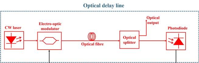
ever, the frequency of the oscillator can be increased, but this does not affect the stability
result because the stabilization is performed at an independent wavelength.
Phase-locked loops (PLLs) are alternative solutions that are widely used in practice
to improve the long-term stability of the OEO signal. In this case, the OEO signal is locked
Electronics 2021, 10, 857 7 of 19
by the PLL signal [78]. The typical configuration of an OEO with a PLL is shown in Figure
7.
Figure
Figure Typical
7. 7. configuration
Typical of an
configuration of OEO withwith
an OEO a PLL configuration.
a PLL configuration.
2.3. General Overview
For an OEO with a PLL configuration, a stable reference signal is required to improve
the In this section
long-term of the paper,
stability. we would
Wen-Hung Tseng like to compare
proposed the performance
another approach to ofimproving
different the
configurations of the OEO in multimode operation: short-term stability (i.e., phase noise)
long-term stability that involves a fiber-delay monitoring mechanism [79]. This mecha-
and long-term stability. In the first table, different configurations of the OEO are described
nism monitors the fiber delay using an injected probe signal. A thermal drift of 10−7 s was
by comparing the SMSR and the phase noise.
achieved after 4000 seconds with the monitoring mechanism.
For Table 1, OEOs with the same or similar frequency were selected (except for the
OEO with a high quality opto-electronic filter) to allow a more accurate and scientific
2.3. GeneralofOverview
comparison the phase noise in different solutions. However, in theory, the OEO has
In this section of the paper, that
a stable phase-noise characteristic we would like to compare
is independent the performance
of the operating frequency of different
[1],
soconfigurations of thecan
higher frequencies OEObeinused
multimode operation: short-term
for the comparison. In the SMSR stability (i.e., phase
comparison, thenoise)
optical delay linestability.
and long-term length andIn the
the bandwidth of the electrical
first table, different and/or optical
configurations of the filter
OEOare aremore
described
important for the
by comparing comparison.
the SMSR and the When considering
phase noise. the phase noise, the injection-locked
OEO achieves
For Table the1,best
OEOsperformance
with the sameamong or the otherfrequency
similar solutions.were
On the other hand,
selected (exceptthefor the
cascaded micro-wave photonic filter solution achieved a better result in terms
OEO with a high quality opto-electronic filter) to allow a more accurate and scientific of the SMSR.
comparison of the phase noise in different solutions. However, in theory, the OEO has a
Table 1. Comparison of the SMSR and the phase noise of the current results for various advanced configurations of the OEO.
stable phase-noise characteristic that is independent of the operating frequency [1], so
higher
Opticalfrequencies
Delay Line can be used for the comparison. In the SMSR comparison,
Phase the optical
Noise (@10 kHz
Configuration Central Frequency SMSR
Length offset from the carrier)
delay line length and the bandwidth of the electrical and/or optical filter are more im-
portant forfiber
7-core the comparison. When considering the phase noise, the injection-locked OEO
Dual-loop OEO [64] From 3.5 GHz to 17.1 GHz 61 dB −100 dBc/Hz
(105the
achieves m) best performance among the other solutions. On the other hand, the cascaded
micro-wave
Single-mode photonic
fibers filter solution achieved a better result in terms of the SMSR.
Injection-locked OEO [68] 10 GHz N/A −130 dBc/Hz
(1 km and 0.7 km)
Erbium-doped fiber
Coupled OEO [72] 10 GHz 72.5 dB −123.6 dBc/Hz
(4 m)
OEO with high-quality Dispersion-shifted
29.99 GHz 83 dB −113 dBc/Hz
opto-electronic filter [73] fiber (3 km)
Cascading microwave Single-mode fibers
17.33 GHz 125 dB −103 dBc/Hz
photonic filter [49] (2 km and 0.2 km)
Narrowband microwave laser Single-mode fibers
From 1.85 GHz to 10.24 GHz 55 dB −116 dBc/Hz
with dual-loop OEO [74] (2.5 km and 3 km)
In Table 2, different solutions are compared to evaluate the performance of the OEO
in terms of long-term stability and phase noise.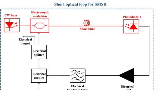
Electronics 2021, 10, 857                                                                                                                8 of 19

                            Table 2. Comparison of the different techniques to achieve long-term stability in the OEO.

                                       Optical Delay Line                                                          Phase Noise (@10 kHz
         Configuration                                           Central Frequency        Long-term Stability
                                            Length                                                                 offset from the carrier)
 Temperature stabilization [75]               N/A                     10 GHz                  0.1 ppm/K                  −143 dBc/Hz
  OEO with feedback-control
                                             15 km                    3 GHz                   0.05 ppm/K                 < −130 dBc/Hz
         loop [76]
   Optical delay stabilization
                                              3 km                    3 GHz                   0.02 ppm/K                 −123 dBc/Hz
          system [77]
                                              500 m
                                                                                             6.98 × 10⁻¹⁴
       OEO with PLL [78]               (Dispersion deduced            3 GHz                                              < −100 dBc/Hz
                                                                                        (average time of 1000 s)
                                              fiber)

                                             The optical delay line system showed good performance in terms of long-term and
                                        short-term stability. The phase-noise performance could be improved by using a longer
                                        optical fiber. An OEO with a PLL does not have good phase noise performance because a
                                        short delay line is used. However, a classic solution such as temperature stabilization has
                                        good phase noise performance and short-term stability.

                                        3. Recent Development of the OEO’s Application
                                            In this section we present and detail some recent advances in the application of OEOs
                                       in different fields as well as some new developments such as integrated OEOs and the
                                       wideband tunable OEO.

                                        3.1. Wideband Tunable Frequency Generation
                                             The conventional OEO has a narrowband tunability, which is a few MHz due to the
                                       bandwidth limitation of the electrical bandpass filter. To improve the tunability of the OEO,
                                       tunable microwave resonators or microwave photonic filters have been proposed [61]. They
                                       can provide tunability from hundreds of MHz up to tens of GHz. In 2010, W. Li published
                                       the first research paper for a wideband tunable OEO [80]. In 2017, a wideband tunable
                                       frequency generator based on a dispersion compensation fiber OEO was proposed that
                                       had a tuning range of 3–42 GHz [81]. The SSB phase noise was lower than −110 dBc/Hz
                                       at a 10 kHz offset from the carrier for the whole tuning range (span of about 39 GHz). A
                                       microwave photonic filter was used for frequency tuning, while the dispersion compensa-
                                       tion fiber was used to compensate for the chromatic dispersion of the single-mode fiber. In
                                       2019, a wideband frequency generator based on frequency division without a bandpass
                                       filter, but biasing the Mach–Zehnder Modulator (MZM) at the minimum transmission
                                       point, was introduced [82]. The wideband signal from 6 GHz to 10 GHz (or 10 GHz to
                                       18 GHz) was obtained depending on the input signal. A phase noise improvement of
                                       5.71 dB was achieved at the output signal [82]. A micro-ring resonator (MRR) is another
                                       possible solution to bring wideband tunability to the OEO configuration [83]. Wideband
                                       frequency generation between 0 and 20 GHz was achieved using an OEO with a MRR,
                                       wherein the SSB phase noise of −95 dBc/Hz was measured at a 10 kHz offset from the
                                       12.23 GHz carrier frequency [83]. The configuration of the OEO with the MRR is shown in
                                       Figure 8.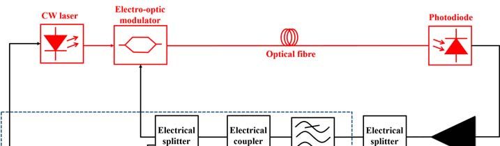
10 GHz to 18 GHz) was obtained depending on the input signal. A phase noise improve-
ment of 5.71 dB was achieved at the output signal [82]. A micro-ring resonator (MRR) is
another possible solution to bring wideband tunability to the OEO configuration [83].
Wideband frequency generation between 0 and 20 GHz was achieved using an OEO with
Electronics 2021, 10, 857 a MRR, wherein the SSB phase noise of −95 dBc/Hz was measured at a 10 kHz9 offset
of 19 from
the 12.23 GHz carrier frequency [83]. The configuration of the OEO with the MRR is
shown in Figure 8.
Figure8.8.Simple
Figure Simpleconfiguration of an
configuration of OEO withwith
an OEO a micro-ring resonator
a micro-ring (MRR).(MRR)
resonator
3.2. Photonic Integrated Chip
3.2. Photonic Integrated Chip
The traditional OEO uses an optical fiber to form the optical delay line. This makes
the OEOTheverytraditional
large and OEO usescases,
in some an optical
bulky fiber
becauseto form the optical
it contains delay
additional line. This makes
components
the OEO very large and in some cases, bulky because it contains
for the improvement of short-term and long-term stabilization, multimode operation, additional components
etc.
(an
foradditional delay line,
the improvement ofadditional
short-term optical and/or electrical
and long-term devices,multimode
stabilization, etc.). To reduce the
operation, etc.
size
(an of the OEO,delay
additional a compact OEO was proposed.
line, additional In theelectrical
optical and/or compact OEO, theetc.).
devices, opticalTofiber
reduce the
was
sizereplaced by a awhispering-gallery-mode
of the OEO, compact OEO was proposed. resonator (WGMR)
In the compact to reduce
OEO, thethe size of the
optical fiber was
OEO [31–33].
replaced by a whispering-gallery-mode resonator (WGMR) to reduce the size of the OEO
The fully integrated OEO based on an InP substrate was first presented by J. Tang et al.
[31–33].
at the Microwave Photonics Conference 2017 [38,84]. All the components were assembled
The fully
in a photonic integrated
integrated chipOEO
(PIC).based on anwaveguide
An optical InP substrate was first
in a spiral shapepresented
was usedby J. Tang et
as an
al. at the
optical Microwave
resonator. WhenPhotonics
a microwaveConference
frequency 2017
was[38,84].
generated Allwith
the components
such an integratedwere assem-
OEO, one of the main handicaps was the length of the delay line. Due to the small size was
bled in a photonic integrated chip (PIC). An optical waveguide in a spiral shape of used
as an
the optical resonator.
spiral-shaped When
delay line, whicha microwave frequency the
was a few centimeters, wasQ-factor
generated
of thewith
OEO such
wasan inte-
grated
very low,OEO, onethe
and thus of phase
the main
noisehandicaps waswere
characteristics the length of the
worse than delay
those of aline. Due to the small
non-integrated
Electronics 2021, 10, x FOR PEER REVIEWOEO.
size ofTherefore, for the integrated
the spiral-shaped OEO,
delay line, an SSB
which wasphase
a few noise of −91 dBc/Hz
centimeters, 10 at
the Q-factora 1-MHz
of 19 of the OEO
offset from the 7.3 GHz carrier was obtained [38]. The integrated OEO and
was very low, and thus the phase noise characteristics were worse than those of a non- its tunability
and short-term
integrated performance
OEO. Therefore, arefor
given
the in Figure 9. OEO, an SSB phase noise of −91 dBc/Hz at
integrated
a 1-MHz offset from the 7.3 GHz carrier was obtained [38]. The integrated OEO and its
tunability and short-term performance are given in Figure 9.
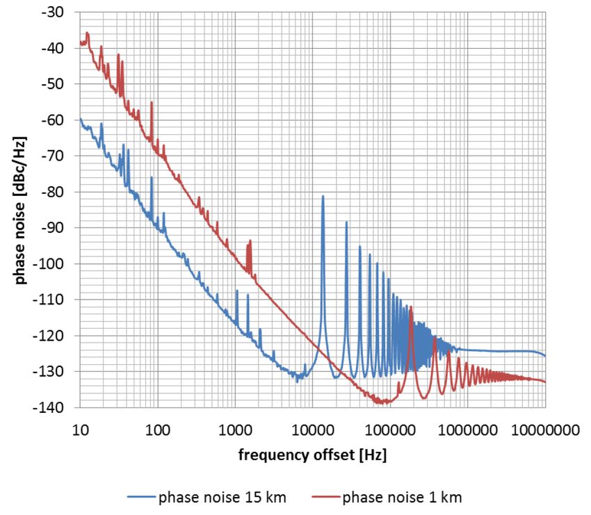
Figure 9. The
Figure integrated
9. The OEO.OEO.
integrated The frequency tunability
The frequency of theof
tunability OEO
the is
OEOaround 20 MHz,
is around with a with
20 MHz, cen- a central
tral oscillation frequency of 7.3 GHz [38]. Reprinted with permission from Reference [38]. Copy-
oscillation frequency of 7.3 GHz [38]. Reprinted with permission from Reference [38]. Copyright
right 2017 IEEE.
2017 IEEE.
In addition to the integrated OEO on the InP substrate, an integrated OEO based on
a silicon substrate was introduced to the literature by W. Zhang and J. Yao in 2018 [85]. A
high-speed phase modulator, a tunable micro-disk resonator and a high-speed photode-
tector were integrated on the silicon-substrate chip. The proposed silicon photonic OEO
was tunable in the frequency range between 3 GHz and 8 GHz. The measured SSB phase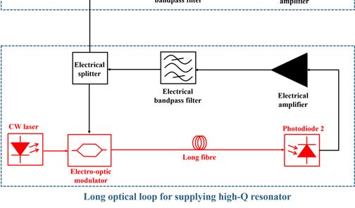
Electronics 2021, 10, 857 10 of 19
In addition to the integrated OEO on the InP substrate, an integrated OEO based on a
silicon substrate was introduced to the literature by W. Zhang and J. Yao in 2018 [85]. A high-
speed phase modulator, a tunable micro-disk resonator and a high-speed photodetector
were integrated on the silicon-substrate chip. The proposed silicon photonic OEO was
tunable in the frequency range between 3 GHz and 8 GHz. The measured SSB phase noise
was –81 dBc/Hz at a 10 kHz offset from the 4.74 GHz RF carrier signal. On the other hand,
a photonic and electronic hybrid OEO was presented in 2019 [86]. In this configuration, the
OEO consisted of photonic and electronic chips that were fabricated separately. An SSB
phase noise of −103 dBc/Hz at a 100 kHz offset from the carrier was measured.
As can be clearly seen from the SSB phase noise measurements of the integrated
OEO [84–86], although the integrated OEOs provide the opportunity to reduce the size and
enable mass production of the OEO in the chip, they unfortunately have poor short-term
stability in the microwave range. However, due to their small size, the long-term stability
of the OEO can be easily improved by temperature stabilization of the chip.
3.3. Optical Signal Distribution for the 5G Radio Access Network
The next-generation 5G radio access network (RAN) has certain requirements to
improve bit rate and spectral efficiency [87]. It is expected that millimeter wave bands
will be used to meet these requirements [88]. The current 4G-RAN technology uses an
electrical local oscillator (LO) in each base station to perform the frequency up-conversion
and down-conversion of the data signal. Unfortunately, the phase-noise performance
is degraded when they are used for the millimeter-wave signal range. The centralized
oscillator’s signal distribution was reported in the literature from several sources [89–92].
For example, in [93], we proposed the use of an OEO as a LO in a 5G RAN fronthaul.
The centralized oscillator signal was distributed to the base stations without the need for
electro-optical and opto-electronic conversion. Radio over fiber [94–96] is proposed as an
efficient and sophisticated solution to distribute the centralized OEO signal. The idea is
Electronics 2021, 10, x FOR PEER REVIEW 11 of 19
shown in Figure 10. The OEO signal is distributed from the central office to the base station
through an optical distribution network (ODN). The data signals and the OEO signal can be
transmitted over the same fiber using a dense wavelength-division-multiplexing (DWDM)
simple,
approach.as well
This as the basehas
approach station, because the
the advantage LO is nothe
of keeping longer
ODN required. Since the
infrastructure LOs
simple,
would
as wellneed
as thetobase
be temperature stabilized
station, because the LOto provide a stable
is no longer clock signal,
required. it isLOs
Since the more cost-
would
effective
need to be totemperature
only developstabilized
one well-stabilized
to provide aoscillator in the
stable clock central
signal, it isoffice
moreand distribute
cost-effective
its signal to the base stations. In addition, the proposal has the advantage thatits
to only develop one well-stabilized oscillator in the central office and distribute thesignal
total
to the base
number stations. In
of oscillators inaddition,
the wholethe proposal
fronthaul has the
system advantage
is reduced. that
This the total
would havenumber of
a positive
oscillators
impact on inthethe wholesavings
energy fronthaul system
of the is reduced.
complex systemThis would
if the haveof
number a positive impact
oscillators on
was re-
the energy savings of the complex system if the number of oscillators was reduced.
duced.
Figure 10.
Figure 10. Use
Useofofan
anOEO
OEOasas
a local oscillator
a local (LO)
oscillator for for
(LO) a 5Ga radio access
5G radio network
access (RAN)
network fronthaul.
(RAN) Reprinted
fronthaul. from Refer-
Reprinted from
ence [93].
Reference [93].
On the other hand, the optical signal distribution of the OEO via an optical fiber pre-
sents some challenges. One of the main challenges is the power penalty due to chromatic
dispersion [97]. The C band is widely used in optical communications because of its ad-
vantages such as a low optical loss (0.2 dB/km), but chromatic dispersion is very dominant
in this band, ranging between approximately 16 and 17 ps/nm/km. Intensity-modulatedFigure 10. Use of an OEO as a local oscillator (LO) for a 5G radio access network (RAN) fronthaul. Reprinted from Refer-
Electronics 2021, 10, 857 11 of 19
ence [93].
On the other hand, the optical signal distribution of the OEO via an optical fiber pre
sentsOn
some challenges.
the other hand, theOneoptical
of thesignal
main distribution
challenges is ofthe
thepower
OEO viapenalty due fiber
an optical to chromati
presents some
dispersion challenges.
[97]. The C bandOne ofisthe main challenges
widely is the power
used in optical penalty due to because
communications chromaticof its ad
dispersion
vantages such[97]. asThe C band
a low is widely
optical loss (0.2used in optical
dB/km), communications
but chromatic because
dispersion of its
is very dominan
advantages such as a low optical loss (0.2 dB/km), but chromatic
in this band, ranging between approximately 16 and 17 ps/nm/km. Intensity-modulated dispersion is very
dominant in this band, ranging between approximately 16 and 17 ps/nm/km. Intensity-
links are negatively affected by the power penalty due to chromatic dispersion. Therefore
modulated links are negatively affected by the power penalty due to chromatic dispersion.
we proposed to use the tunable dispersion-compensation module (TDCM) in each base
Therefore, we proposed to use the tunable dispersion-compensation module (TDCM) in
station
each [93], which
base-station [93],iswhich
shown in Figure
is shown 10. The
in Figure 10. TDCM
The TDCM is aisdevice based
a device basedon
onBragg
Bragg grating
that provides a way to compensate for the chromatic dispersion in the
gratings that provides a way to compensate for the chromatic dispersion in the C band with C band with respec
to the actual
respect fiber fiber
to the actual length. To To
length. testtest
the
theperformance
performance of ofthe
theoptical
optical signal
signal distribution, we
distribution,
we employed the experimental setup shown
employed the experimental setup shown in Figure 11. in Figure 11.
Figure11.
Figure 11. Experimental
Experimentalsetup
setupfor
fordispersion
dispersion penalty
penalty measurements
measurements withwith
and and without
without tunable
tunable
dispersion-compensation
dispersion-compensation module
module (TDCM).
(TDCM).
For
Forthe
theexperiment,
experiment,we wesetset
upupanan
optical delay
optical lineline
delay in combination
in combinationwithwith
a vector
a vector net
network analyzer (VNA). This configuration provided the ability to apply a wideband RF
work analyzer (VNA). This configuration provided the ability to apply a12wideband
Electronics 2021, 10, x FOR PEER REVIEW of 19 RF
signal to the optical delay line to track the full spectrum of the dispersion penalty. When the
signal
OEO to used
was the optical
insteaddelay
of the line to track
described the full spectrum
experimental setup, weof thehad
only dispersion penalty. When
the opportunity
the OEO was used instead of the described experimental setup, we only
to investigate a single frequency. Therefore, we could obtain limited experimental data had the oppor
tunity
data
relevant totoinvestigate
relevant the a single
todispersion
the dispersion
penalty.frequency.
penalty. Therefore,
The VNA
The VNA thewe
provided
provided could
RFthe obtain
RF signal
signal limited
with awith experimenta
a range
range of
of about
about
45 GHz.45 GHz. The results
The results for power
for the the power penalty
penalty withwith
andand without
without thethe TDCM
TDCM areare shown
shown in
in Figure
Figure 12.12.
Figure
Figure12.
12.Power-penalty measurements
Power-penalty from
measurements 10 MHz
from to 45to
10 MHz GHz
45 over
GHzaover
20-km
a optical fiber. Re-
20-km optical fiber.
printed from Reference [93].
Reprinted from Reference [93].
The results show that the TDCM can be used in any base station to compensate for
chromatic dispersion in the C band. In other words, to avoid the power penalty of the
OEO signal distribution over the ODN, the TDCM can be used at each base station. The
only challenge associated with the proposal is that the TDCM requires knowledge of the
exact optical length. This challenge can be solved by using a proportional-integral-deriv-Electronics 2021, 10, 857 12 of 19
The results show that the TDCM can be used in any base station to compensate for
chromatic dispersion in the C band. In other words, to avoid the power penalty of the OEO
signal distribution over the ODN, the TDCM can be used at each base station. The only
challenge associated with the proposal is that the TDCM requires knowledge of the exact
optical length. This challenge can be solved by using a proportional-integral-derivative
(PID) controller so that the TDCM can be automatically tuned by comparing the maximum
RF power seen in the RF spectrum. On the other hand, there are other possible options,
such as using the 1310-nm wavelength or special fibers such as a dispersion-shifted fiber
(DSF). However, the use of the 1310-nm wavelength has some disadvantages such as larger
optical losses compared to the C band, and the optical nonlinearities are larger in this
band. In addition, DSF requires modification of the infrastructure, which might not be a
cost-effective and feasible approach for a RAN.
3.4. Application for SMSR, FSR and Phase Noise Measurements
As mentioned several times in the text, one of the main challenges associated with
the OEO is multimode operation. There are some analytical approaches to calculating
the SMSR [98,99]. These analytical approaches are challenging and require some system
values. We have developed an application of the OEO based on the single-loop OEO
with an optical fiber path selector published in 2020 [100]. The application allows rapid
measurements of the SMSR, FSR and phase noise of the OEO for different optical lengths.
Electronics 2021, 10, x FOR PEER REVIEW 13 of 19
In addition, various electrical bandpass filters can be tested to find the optimum one for
the OEO. The application is shown in Figure 13.
Figure
Figure OEOapplication
13.13.OEO application to
to measure
measure the
thephase
phasenoise, SMSR
noise, SMSRandand
freefree
spectral range range
spectral (FSR) of(FSR)
the electrical bandpassbandpass
of the electrical filters
at different
filters optical
at different fiber lengths.
optical Reprinted
fiber lengths. from Reference
Reprinted [100]. [100].
from Reference
In the
In the configuration
configuration shown
shownin inFigure
Figure13,13,a aspectrum
spectrum analyzer
analyzer(SA)
(SA)is used to verify
is used to verify
that the Barkhausan conditions are satisfied, and a signal source analyzer (SSA) is operated
that the Barkhausan conditions are satisfied, and a signal source analyzer (SSA) is oper-
to measure the phase noise, FSR and SMSR. The proposed application has the advantage
ated to measure the phase noise, FSR and SMSR. The proposed application has the ad-
of verifying, measuring and testing the various electrical bandpass filters in different
vantage of verifying,
optical delay lines to measuring and testing
find the optimum one. the various
In this electrical
application, thebandpass filters are
optical lengths in dif-
ferent optical delay lines to find the optimum one. In this application, the
changed without the requirement to exchange the optical connectors due to the optical path optical lengths
are changed
selector’s withoutto
capability the requirement
switch betweento exchange
different the
fiber optical
spools. connectors
Figure 14 is a due to the optical
photograph of
path selector’sapplication
the proposed capability setup,
to switch
whilebetween different
Table 3 shows the fiber spools. Figure
experimental results of14 the
is aOEO
photo-
graph
around of9.63
the proposed
GHz, where application setup,
the different while
optical Table
lengths are3 formed.
shows the experimental results of
the OEO around 9.63 GHz, where the different optical lengths are formed.ated to measure the phase noise, FSR and SMSR. The proposed application has the ad-
vantage of verifying, measuring and testing the various electrical bandpass filters in dif-
ferent optical delay lines to find the optimum one. In this application, the optical lengths
are changed without the requirement to exchange the optical connectors due to the optical
Electronics 2021, 10, 857 path selector’s capability to switch between different fiber spools. Figure 14 is 13
a photo-
of 19
graph of the proposed application setup, while Table 3 shows the experimental results of
the OEO around 9.63 GHz, where the different optical lengths are formed.
Figure 14.14.
Figure Photograph ofof
Photograph the
theproposed
proposedapplication
application of
of the
the OEO combinedwith
OEO combined withthe
theoptical
opticalfiber
fiber path
path selector.
selector.
Table
Table3.3.FSR,
FSR,SMSR
SMSRand
andphase
phasenoise
noisemeasurements
measurementsofofthe
thesingle-loop
single-loopOEO
OEOfor
fordifferent
differentoptical
optical
lengths [100].
lengths [100].
Phase Noise @1Phase
Phase Noise @1 kHz
Phase Noise @10
Noise @10
Fiber Length
Fiber Length FSR
FSR SMSR SMSR kHz Offset
Offset kHzkHz Offset
Offset
(km)
(km) (kHz)
(kHz) (dB) (dB)
(dBc/Hz) (dBc/Hz)
(dBc/Hz) (dBc/Hz)
1.25
1.25 158.5
158.5 78.1 78.1 −73.8 −73.8 −120.7
−120.7
2.50
2.50 79.3
79.3 71.1 71.1 −80.6 −80.6 −123.3
−123.3
5.00 40.2 62.5 −100.9 −123.3
5.00
7.50 40.2
27.2 39.9 62.5 −104.7−100.9 −123.3
−125.0
7.50 27.2 39.9 −104.7 −125.0
Electronics 2021, 10, x FOR PEER REVIEW 14 of 19
According to the results in Table 3, the tradeoff between the phase noise and the SMSR
According to the results in Table 3, the tradeoff between the phase noise and the
is clearly seen when the length of the optical delay line is alternated. This application can
SMSR is clearly
be used seen when
to test various the length
electrical bandpassof the optical
filters in thedelay line is
OEO loop to alternated. This applica-
find the optimum filter
tion can be
optimum
in terms of used
filter in to
phase testand
terms
noise various
of SMSR.electrical
phase noise bandpass
andoptimum
Also, the SMSR. Also,filters
the
optical inoptimum
delaythe OEO
line loop
canoptical
be todelay
find line
determined the
can be determined with the use of this application. In addition, with the proposed
with the use of this application. In addition, with the proposed application, the phase noise appli-
cation,
result the
of thephase
OEOnoise
can beresult of the
obtained withOEO can be
the SSA. Forobtained
instance,with the SSA.
in Figure For
15, the instance,
phase noise in
performance
Figure 15, the of an OEO
phase noisewith a length of of
performance 7.5ankm is presented.
OEO with a length of 7.5 km is presented.
Figure
Figure Phase-noiseperformance
15.Phase-noise
15. performance of
of an OEO
OEO with
withaa7.5
7.5km
kmoptical
opticaldelay
delayline length.
line length.
As can be clearly seen in Figure 15, −104.7 dBc/Hz and −125.0 dBc/Hz were at 1 kHz
and 10 kHz offset from the 10.45 GHz carrier. In this application, the phase noise of the
OEO for different optical fiber lengths could be easily measured by adjusting the optical
fiber path selector.Electronics 2021, 10, 857 14 of 19
As can be clearly seen in Figure 15, −104.7 dBc/Hz and −125.0 dBc/Hz were at 1 kHz
and 10 kHz offset from the 10.45 GHz carrier. In this application, the phase noise of the
OEO for different optical fiber lengths could be easily measured by adjusting the optical
fiber path selector.
4. Conclusions
The OEO is a very well-known, high-frequency oscillator for generating low-phase
microwave and millimeter wave signals and is used daily in various fields of science,
technology and engineering. It has already been shown that an OEO can generate a
millimeter wave signal up to the W band. The OEO has the advantage that the oscillator’s
phase noise is independent of the operating frequency. However, the OEO might require
stabilization for short-term, long-term and multimode operation.
Moreover, the OEO can be developed as a tool/application for various scientific
and engineering fields. The wideband OEO was introduced to generate high-frequency
signals in the microwave and millimeter wave signal ranges. This enabled the OEO to
be tunable up to GHz and above. In 2017, the manufacture of an OEO on a photonic-
integrated chip was added to the literature. The next generation of 5G RAN requires a
low-phase-noise oscillator in the millimeter wave range. Thus, we propose to implement
the OEO in the central station of the 5G RAN, defined as a LO for frequency up-conversion
and down-conversion. This eliminates the requirement for a LO in each base station,
and the clock distribution is also conducted centrally. Moreover, due to its structure, the
OEO does not require opto-electronic/electro-optical signal conversion, which can be
classified as another advantage. On the other hand, the simple, single-loop OEO cannot
meet the requirements of the centralized OEO for 5G RAN. Thus, an injection-locked,
millimeter wave OEO with temperature-stabilized components might be employed to
exhibit the best performance as a centralized LO for 5G RAN. Furthermore, by combining
the optical fiber path selector with the single-loop OEO, we developed an application to
measure the FSR, SMSR and phase noise of the OEO for different optical fiber lengths. This
application is also practical to test different electrical bandpass filters and find the optimum
performance. In the future, we would like to improve the application so that it can be used
for testing/verifying/measuring different configurations of OEOs, such as injection-locked,
multi-loop, etc. For injection-locked or multi-loop configurations, an additional optical
fiber path selector (one or more) is required to find the optimum configuration of the OEO
by comparing the SMSR and the phase noise.
In the current state of the art, one of the limitations is designing a stable OEO on
the photonic integrated chip. In order to enable mass production of the OEO, which
would make it possible to use the OEO in different scientific areas, photonic integration
might be useful. However, because of its short delay line length, the photonic integrated
OEO has a poor short-term stability. A future study should focus on improving the
short-term stability of the integrated OEO. A high Q-factor resonator can be implemented
for the photonic integrated chip. If this is achieved, the integrated OEO can easily be
combined into the 5G RAN as a centralized local oscillator. On the other hand, the single-
loop OEO has its own limitations for long-term stability and multi-mode operation. A
variety of different configurations are proposed to reduce the challenges. Multi-loop,
injection-locked or coupled OEOs have been used for many years to improve the multimode
operating characteristics of the OEO. Moreover, OEOs with a feedback control loop, PLL
and temperature stabilization of the optical fiber as well as an electrical bandpass filter
are used to reduce the frequency drift of the oscillator signal. Another topic for future
research should be the sophisticated design of wideband, tunable, integrated and ordinary
OEO operating in the millimeter wave range with acceptable phase noise performance
(< −120 dBc @10 kHz offset from the carrier).
Author Contributions: Conceptualization, methodology, investigation and resources M.A.I., and
B.B.; formal analysis and validation B.B.; writing—original draft preparation M.A.I.; writing—reviewYou can also read