1.4l TSI Engine with Dual-charging - Self-study Programme 359 Design and Function
←
→
Page content transcription
If your browser does not render page correctly, please read the page content below
Service Training

Self-study Programme 359

1.4l TSI Engine with Dual-charging

Design and Function

                                     1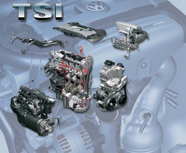
The 1.4l TSI* engine is the world’s first petrol engine with direct petrol injection and dual-charging. Volkswagen is
           thus laying another milestone in engine development.

           * The term “TSI” is a protected abbreviation of Volkswagen.

                                                                                                       S359_002

           On the following pages, we will introduce you to the design and function of the new 1.4l TSI engine with dual-
           charging.

                                                                                                 NEW                    Important
                                                                                                                        Note

    The self-study programme shows the design and   For current testing, adjustment and repair
    function of new developments.                   instructions,
    The contents will not be updated.               refer to the relevant service literature.

2
Contents

Introduction . . . . . . . . . . . . . . . . . . . . . . . . . . . . . . . . . . . . . . . . . . . . . . . . . . 4

Engine mechanics . . . . . . . . . . . . . . . . . . . . . . . . . . . . . . . . . . . . . . . . . . . . . . 6
  Poly-V-belt drive . . . . . . . . . . . . . . . . . . . . . . . . . . . . . . . . . . . . . . . . . . . . . . . . . 6
  Timing chain . . . . . . . . . . . . . . . . . . . . . . . . . . . . . . . . . . . . . . . . . . . . . . . . . . . . 7
  Cylinder block . . . . . . . . . . . . . . . . . . . . . . . . . . . . . . . . . . . . . . . . . . . . . . . . . . . 8
  Cylinder head and valve train . . . . . . . . . . . . . . . . . . . . . . . . . . . . . . . . . . . . 10
  Dual-charging with supercharger and turbocharger . . . . . . . . . . . . . . . . . 11
  Crankcase breather and ventilation . . . . . . . . . . . . . . . . . . . . . . . . . . . . . . . 21
  Oil system . . . . . . . . . . . . . . . . . . . . . . . . . . . . . . . . . . . . . . . . . . . . . . . . . . . . . 22
  Dual-circuit cooling system . . . . . . . . . . . . . . . . . . . . . . . . . . . . . . . . . . . . . . 24
  Demand-regulated fuel system . . . . . . . . . . . . . . . . . . . . . . . . . . . . . . . . . . . 26
  Exhaust system . . . . . . . . . . . . . . . . . . . . . . . . . . . . . . . . . . . . . . . . . . . . . . . . . 27

Engine Management . . . . . . . . . . . . . . . . . . . . . . . . . . . . . . . . . . . . . . . . . . 28
  System Overview . . . . . . . . . . . . . . . . . . . . . . . . . . . . . . . . . . . . . . . . . . . . . . 28
  CAN networking . . . . . . . . . . . . . . . . . . . . . . . . . . . . . . . . . . . . . . . . . . . . . . 30
  Engine Control Unit . . . . . . . . . . . . . . . . . . . . . . . . . . . . . . . . . . . . . . . . . . . . . 31
  Sensors . . . . . . . . . . . . . . . . . . . . . . . . . . . . . . . . . . . . . . . . . . . . . . . . . . . . . . . 32
  Actuators . . . . . . . . . . . . . . . . . . . . . . . . . . . . . . . . . . . . . . . . . . . . . . . . . . . . . . 46
  Functional Diagram . . . . . . . . . . . . . . . . . . . . . . . . . . . . . . . . . . . . . . . . . . . . . 58

Service . . . . . . . . . . . . . . . . . . . . . . . . . . . . . . . . . . . . . . . . . . . . . . . . . . . . . . 60

Test Yourself . . . . . . . . . . . . . . . . . . . . . . . . . . . . . . . . . . . . . . . . . . . . . . . . . . 62

                                                                                                                             3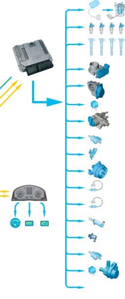
Introduction

      Special Technical Features
      The special concept behind this engine is, above all,
      the combination of direct petrol injection, dual-
      charging and downsizing.

      - Volkswagen used direct petrol injection for the first
        time in the Lupo FSI model year 2001.
      - In dual-charging, the engine is charged by a
        mechanical compressor and/or a turbocharger.

      - Downsizing is replacing a large-capacity engine
        with a powerplant with smaller displacement and/
        or fewer cylinders. This reduces the internal friction
        and this the fuel consumption without the power or
        torque being reduced.
                                                                                                            S359_003

      Thanks to this concept, it has greater performance
      than engines with the same output and also consumes
      less fuel. It therefore meets customer demands for
      economic FSI engines with a high level of dynamism.

      Technical features
      ●   Two output versions delivering 103kW and 125kW         ●   Plastic intake manifold
      ●   Bosch Motronic MED 9.5.10                              ●   Continuous inlet camshaft timing adjustment
      ●   Homogenous mode (Lambda 1)                             ●   Grey cast iron cylinder block
      ●   Double injection catalytic converter heating           ●   Steel crankshaft
      ●   Turbocharger with waste gate                           ●   Duo-centric oil pump
      ●   Additional mechanical supercharger                     ●   Dual-circuit cooling system
      ●   Intercooler                                            ●   Fuel system regulated according to requirements
      ●   Maintenance-free timing chain                          ●   High-pressure fuel pump with a delivery pressure
      ●   Engine cover with vacuum tank for the intake               of up to 150 bar
          manifold flap control

4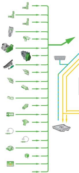
Technical data
Torque and power diagram
                1.4l/103kW TSI engine                                      1.4l/125kW TSI engine
   Nm                                                kW             Nm                                        kW

                                               rpm                                                      rpm

                Torque [Nm]                    S359_093                    Torque [Nm]
                                                                                                        S359_094

                Power [kW]                                                 Power [kW]

Technical data
Engine code                             BMY                                 BLG
Type                                    4-cylinder in-line engine           4-cylinder in-line engine
Displacement                            1390                                1390
Bore                                    76.5                                76.5
Stroke                                  75.6                                75.6
Valves per cylinder                     4                                   4
Compression ratio                       10:1                                10:1
Maximum output                          103 kW at 6,000 rpm                 125 kW at 6,000 rpm
Maximum torque                          220 Nm at 1,500 – 4,000 rpm         240 Nm at 1,750 – 4,500 rpm
Engine management                       Bosch Motronic MED 9.5.10           Bosch Motronic MED 9.5.10
Fuel                                    Super unleaded RON 95               Super Plus at RON 98
                                                                            (Super unleaded at RON 95 with slightly
                                                                            higher consumption and torque
                                                                            reduction in the low rev ranges)
Exhaust gas treatment                   Main catalytic converter,           Main catalytic converter,
                                        Lambda control                      Lambda control
Emissions standard                      EU 4                                EU 4

           The different output and torque levels are achieved using software. The engine mechanics are the same
           in both engines.

                                                                                                                      5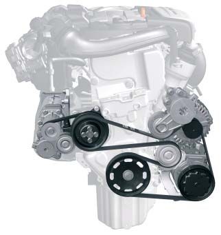
Engine mechanics

      Poly-V-belt drive
      The 1.4l TSI engine has two poly-V-belts.

      - The ancillary component drive belt is a six-groove poly-V-belt. It drives the coolant pump, the alternator and the
        air-conditioning compressor from the camshaft pulley.
      - The supercharger drive belt is a five-groove poly-V-belt. It drives the compressor via the magnetic clutch pulley
        when the magnetic clutch is engaged.

      A tensioning pulley ensures that the ancillary component and supercharger belts are correctly tensioned. The
      tensioning pulley after the crankshaft pulley also ensures that the poly-V-belt runs correctly around the crankshaft
      pulley and coolant pump pulley.

        Supercharger                                                                               Ancillary components
           drive belt                                                                              drive belt

                                                                                                   Belt tensioner
      Compressor belt
         pulley

                                                                                                   Alternator
                                                                                                   belt pulley
           Tensioning
               pulley
                                                                                                   Tensioning pulley

      Coolant pump pulley
      Pulley for supercharger magnetic
      clutch N421
                                                                                                   Air-conditioning
                                                                                                   compressor
                                                                                      S359_004     belt pulley

                                                   Camshaft belt
                                                      pulley

6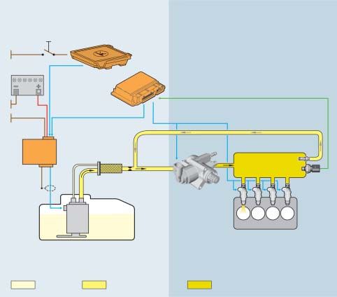
Chain drive
Both the camshafts and also the oil pump are driven by the crankshaft via a maintenance-free timing chain.

Camshaft drive                                             Oil pump drive

The toothed chain drive has been optimised due to the      The oil pump is driven by a toothed chain with 8 mm
greater loading. The toothed chain has hardened pins       pitch for improved sound.
and heavy-duty link plates that have been adapted to       It is tensioned by a spring-loaded chain tensioner.
the chain forces.
The toothed chain is tensioned by a hydraulic chain
tensioner.

                 Sprocket for                                                       Outlet camshaft
     inlet camshaft with vane                                                       sprocket
                     adjuster

                Sprocket for                                                        Slide rail
              camshaft drive

              Tensioning rail                                                       Sprocket for driving
                                                                                    camshafts and oil pump

                  Hydraulic                                                         Spring-loaded
             chain tensioner                                                        chain tensioner

             Oil pump drive                                                         Oil pump sprocket
              toothed chain

                                                                      S359_005

Camshaft timing adjustment
A load- and engine speed-dependent vane adjuster           The camshaft adjustment allows:
is used for the continuous inlet camshaft adjustment.
The adjustment range is a maximum 40° crank angle.         - Very good internal exhaust gas recirculation and
                                                           - improved torque band.

                                                                                                                 7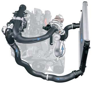
Engine Mechanics

      Cylinder block
      The cylinder block on the 1.4l TSI engine is made from grey cast iron with lamellar graphite. This guarantees
      sufficient operating safety at the high combustion pressures of the TSI engine. Due to the high strength of a cylinder
      block made from grey cast iron with lamellar graphite compared with one made from diecast aluminium,
      the camshaft may be removed.

                                             Cylinder lining

                            Outer wall

                                                                                   S359_006

      As with the 1.4l/66kW and 1.6l/85kW FSI engines, the cylinder block has a so-called open-deck design. This means
      that there are no webs between the outer wall and the cylinder lining.

      This has two advantages:

      - No air bubbles can form in this area which would lead to ventilation and cooling problems particularly with the
        dual-circuit cooling system,
      - When the cylinder head is bolted to the cylinder block, the cylinder liner deformation caused by the decoupling
        of the cylinder liner and cylinder block is less and more even than with a closed-deck design with webs. This
        results in lower oil consumption as the piston rings compensate this deformation better.

                You will find further information on the 1.4l/66kW and 1.6l/85kW FSI engines in self-study programmes
                296 “The 1.4l and 1.6l. FSI engine with timing chain” and 334 “The fuel system in
                FSI engines”.

8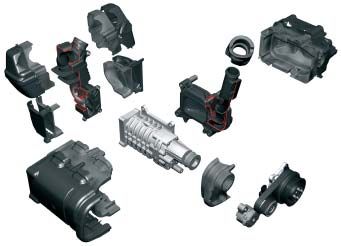
Crankshaft drive
The crankshaft drive consists of the crankshaft, the connecting, the bearing shell, the piston and the piston pin.
Several modifications have been made to the crankshaft drive as the forces occurring on the 1.4l TSI engine are
considerably higher than with the previous FSI engines.

                                                                                       Piston

                 Piston pin
                                                                                       Coated piston
                                                                                       skirt

                                                                                       Connecting rod

                                                                                       Camshaft

                                                                         S359_007

Piston

The pistons are made from diecast aluminium.                  The friction of the piston package has been reduced
A combustion chamber recess with a deflector has              by a graphite coating on the piston skirt and a greater
been worked into the piston base. This leads to a             skirt-to-wall clearance of 55 µm.
strong swirling of the intake air and thus to a very
good mixture formation.
The outlet side of the piston is cooled with a piston         The piston pin diameter has been increased from 17 to
cooling system. The jets open at 2.0 bar.                     19 mm due to the high ignition pressure.

Camshaft                                                      Connecting rod

The forged crankshaft is made from steel and is stiffer       The connecting rods are fracture-split. Therefore only
than the cast crankshaft on the                               the same two components fit together, they are cheap
1.4l/66kW FSI engine.                                         to produce and good positive engagement is formed.
Above all, this reduces the noises from the engine.

                                                                                                                        9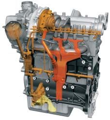
Engine Mechanics

       Cylinder head and valve train
       The cylinder head is the same as on the 1.4l/66kW FSI          Cylinder head
       engine except for a few modifications.

       Several changes have been made to the valve train
       due to the greater loads and exhaust gas
       temperatures.

       ●   Due to the higher loads, the outlet valves are
           reinforced on the valve seats and the valve springs
           are heat-treated.
       ●   Due to the higher exhaust gas temperatures, the
           outlet valves are filled with sodium for better heat
           transfer. This reduces the temperature at the outlet
           valves by approx. 100°C.
                                                                      Outlet valve            Inlet valve          S359_008

       Camshaft case

       The camshafts, which are mounted on three bearings,        High-pressure                    Camshaft case
       are inserted into the camshaft case. Their axial play is   fuel pump

       limited by the cover and the camshaft case.
                                                                                   Roller tappet

       The high-pressure fuel pump is bolted to the camshaft
       case. It is driven by a double cam on the inlet
       camshaft. Due to the higher injection pressures and
       the fuel quantities to be delivered compared with
       previous FSI engines, the pump stroke has been
       increased from 5 to 5.7 mm. The friction is reduced by
       a roller tappet between the high-pressure fuel pump
       and camshaft and halves the drive moment of the
       high-pressure fuel pump.
                                                                                                                   S359_097
                                                                  Inlet camshaft                    Pump cam

                                                                             The seal between the camshaft case and
                                                                             cylinder head is formed with a liquid
                                                                             gasket. Please note the repair instructions in
                                                                             ELSA.

10
Dual-charging with supercharger and turbocharger
Current charged engines mostly use turbochargers. The 1.4l TSI engine is the first to use a combination of
supercharger and turbocharger. That means the engine is charged by a supercharger in addition to the
turbocharger depending on the torque requirements.
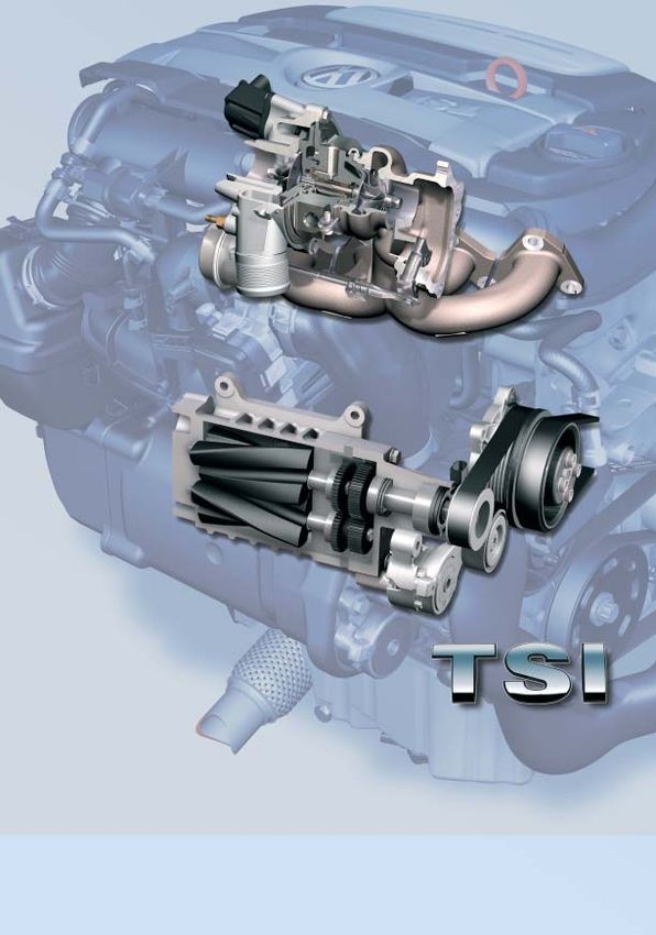
Supercharger
The supercharger is a mechanical charger that is
activated by a magnetic clutch.
Advantages:
- Faster build up of boost pressure
- High torque at low revs
- Only activated when required
- No external lubrication and cooling necessary
Disadvantages:
- Requires drive power from engine
- Boost pressure is produced at any engine speed
S359_009
and is then regulated with part of the generated Mechanical
power being lost again supercharger
Turbocharger Turbocharger
The turbocharger is constantly powered by the
exhaust gas.
Advantages:
- Very good efficiency due to use of exhaust gas
energy
Disadvantages:
- In a small engine, the boost pressure produced in
the low rev ranges is not sufficient to generate high
torque
- High thermal loading
S359_092
11Engine Mechanics
Schematic diagram of all supercharging components
The schematic diagram shows the basic set-up of the “dual-supercharging” system and the path of the fresh intake
air.
Regulating flap Mechanical Intake manifold pressure sender G71 with
control unit J808 supercharger intake air temperature sender G42
Supercharger Fresh air
drive belt
Intake manifold
pressure sender
(supercharger) G583 Air filter
with intake air
Intake manifold
temperature sender
G520 Throttle valve
module J338
Magnetic clutch Charge air pressure sender
G31 with intake air
temperature sender G299
Intercooler
Ancillary
components drive Charge pressure
belt control solenoid valve N75
Exhaust manifold
Catalytic
converter
Pressure
canister
Exhaust
gas
Turbocharger air Turbocharger Waste gate flap S359_010
recirculation valve N249
Air is drawn in through the air filter. The air flows from the turbocharger via the intercooler
The position of the regulating flap is defined in the and the throttle valve module into the intake manifold.
regulating flap control unit determining whether the
air flows via the supercharger and/or straight to the
turbocharger.
12Working ranges of the supercharging components
The diagram shows the working ranges of the mechanical supercharger and the turbocharger. Depending on the
torque requirements, the engine control unit determines whether the required boost pressure is generated and, if
yes, how. The turbocharger works during the all of the coloured areas. The exhaust gas power is not sufficient in the
lower rev ranges to produce the required boost pressure on its own, however.
Constant boost range of supercharger
From a minimum torque requirement and up to an engine speed of 2,400 rpm, the supercharger is
constantly activated. The supercharger boost pressure is controlled via the regulating flap control unit.
Requirement-dependent boost range of supercharger
Up to a maximum engine speed of 3,500 rpm, the supercharger is activated when necessary. This is, for
example, necessary when the car is driven at a constant speed in this range and then accelerates quickly.
Due to the slow response of the turbocharger, acceleration would be delayed (turbo lag). Therefore the
supercharger is activated and the required boost pressure is reached as quickly as possible.
Exclusive turbocharger boost range
In the green area, the turbocharger manages to produce the necessary boost pressure on its own. The
boost pressure is controlled by the charge pressure control solenoid valve.
Torque [Nm]
Engine speed [rpm]
S359_011
13Engine Mechanics
Implementation of working ranges
Depending on the load and rev range, the engine control unit calculates how the required quantity of fresh air
should reach the cylinder to create the required torque. It determines whether the turbocharger can produce the
boost pressure on its own or whether the compressor needs to be activated.
Naturally aspirated mode at low load
Regulating flap
control unit J808
The regulating flap is fully open in naturally aspirated
mode. The intake air flows via the regulating flap
control unit to the turbocharger. The turbocharger is
already driven by the exhaust gas, but the exhaust
gas energy is so low that it only produces a small
Throttle valve
boost pressure.
module J338
The throttle valve is opened depending how far the
driver presses the accelerator and there is a vacuum
in the intake manifold.
Turbocharger S359_015
Supercharger and turbocharger operation at higher
loads and engine speeds up to 2,400 rpm Supercharger
Intake manifold pressure Regulating flap
In this range, the regulating flap is closed or partly sender (supercharger) control unit J808
opened to regulate the boost pressure. The G583
supercharger is activated via a magnetic clutch and is
driven by the supercharger drive belt. The
supercharger draws in air and compresses it. The
compressed fresh air is pumped by the supercharger
to the turbocharger. There the compressed air is
Throttle valve
compressed even more.
module J338
The boost pressure of the supercharger is measured
by the intake manifold pressure sender G583 and Charge air pressure
regulated by the regulating flap control unit. The sender G31
overall boost pressure is measured by the charge air
pressure sender G31.
The throttle valve is completely open. A pressure of up
to 2.5 bar (absolute) is built up in the intake manifold.
Magnetic
clutch
Turbocharger S359_016
14Turbocharger and supercharger operation at high
loads and revs between 2,400 and 3,500 rpm Supercharger Regulating flap
control unit J808
In this range, the boost pressure is produced at, for
example, constant speed, by the turbocharger alone.
If the car now accelerates quickly, the turbocharger
would be too slow to generate the boost pressure fast
enough. There would be turbo lag. To avoid this, the
engine control unit activates the supercharger briefly Throttle valve
module J338
and adjusts the regulating flap control unit according
to the required boost pressure. It helps the
turbocharger produce the necessary boost pressure.
Magnetic
clutch
Turbocharger S359_017
Turbocharger operation Supercharger Regulating flap
control unit J808
From an engine speed of approx. 3,500 rpm, the
turbocharger can produce the required boost
pressure on its own at any load point.
The regulating flap is fully open and the intake air
flows straight to the turbocharger. The exhaust gas Throttle valve
energy is now sufficient in all conditions to produce module J338
the boost pressure with the turbocharger.
Charge air pressure
The throttle valve is completely open. A pressure of up sender G31
to 2.0 bar (absolute) is built up in the intake manifold.
The boost pressure of the turbocharger is measured
with the charge air pressure sender G31 and
regulated by the charge pressure control valve.
Magnetic Charge pressure
clutch control solenoid
valve N75
S359_033
Turbocharger
15Engine Mechanics
Supercharger
Pulley for magnetic
Supercharger drive clutch for supercharger
Supercharger Coolant pump
The supercharger is activated as required and is drive belt pulley
driven by the coolant pump via an auxiliary drive.
The auxiliary drive is activated with a maintenance-
free magnetic clutch on the coolant pump module.
Due to the ratio of the crankshaft belt pulley to the
supercharger belt pulley as well as a internal
supercharger gear ratio, the supercharger turns at
five times the crankshaft speed. The maximum speed
of the supercharger is 17,500 rpm.
Supercharger
Compressor belt Camshaft belt
pulley Tensioning pulley
pulley
S359_014
The supercharger may not be opened.
The chamber containing the speed step
gear and the synchronous gear is filled
with oil. It is filled for life.
Rotors S359_037
Synchronous gear Speed step gear
Mechanical supercharger Rotors
The mechanical supercharger is bolted to the cylinder
block on the intake manifold side after the air filter.
Due to the shape of its two compressor rotors, it is also
called a twin-screw supercharger.
The boost pressure is controlled via a regulating flap
control unit. The maximum boost pressure that the
supercharger produces is about 1.75 bar (absolute).
Pressure side Suction side
S359_023
16How it works:
Supercharger function
Pressure side Suction side
The two supercharger rotors have been designed so
Rotors Mechanical
that, when they rotate, the space on the intake side supercharger
becomes larger. The fresh air is drawn in and
transferred to the pressure side of the supercharger
by the rotors.
On the pressure side, the chamber between the two
supercharger rotors becomes smaller again. The air is
pushed towards the turbocharger.
From
Regulating flap air filter
control unit J808
S359_019
To turbocharger
Supercharger boost pressure regulation
Pressure side Suction side
Intake manifold pressure
The boost pressure is regulated by the position of the sender (supercharger)
regulating flap. When the regulating flap is closed, G583 with Mechanical
the supercharger produces the maximum boost intake air temperature supercharger
sender G520
pressure at this engine speed. The compressed fresh
air is pumped to the turbocharger. If the boost
pressure is too high, the regulating flap is opened
slightly. Now part of the intake air is sent to the
turbocharger and the rest via the partly opened
regulating flap to the intake side of the supercharger.
The boost pressure is reduced. On the intake side, the
air is drawn in again and compressed. This relieves
supercharger and the required drive power for the From
Regulating flap air filter
supercharger is reduced. The boost pressure is
control unit J808
measured by the intake manifold pressure sender S359_013
(supercharger) G583.
To turbocharger
17Engine Mechanics
Noise insulation of supercharger
Due to the arrangement of the supercharger in the direction of the passenger cell, the remaining noises can be
heard by the occupants. Several measures have been taken to reduce the noise level.
To keep the mechanical noise from the supercharger To reduce the noises upon intake and compression ...
low ...
- both sides (fill and discharge side) of the
- the gearing has been modified, e.g. meshing angle supercharger have been sound-proofed,
and twisting play, - the supercharger has been encapsulated and the
- the supercharger shafts have been stiffened and housing parts also lined with insulating foam.
- the supercharger case has been reinforced with
special ribs.
Sound-proofing on fill Housing
side
Insulating foam
Insulating foam Sound-proofing on
discharge side
Housing Supercharger Supercharger
S359_104 drive belt
Supercharger Magnetic clutch
During fast acceleration, the supercharger When the magnetic clutch is switched off,
can “whine” at rev ranges between three leaf springs pull the friction plate back
2,000 – 3,000 rpm. This is the normal to the starting position.
turbine-like operating noise of a Due to the high forces, a normal “clicking”
supercharger. of the magnetic clutch can occur. This can
occur up to an engine speed of 3,400 rpm.
18Turbocharger system components
Turbocharger module Turbocharger
module
The turbocharger forms a module with the exhaust Turbocharger air Oil connection
manifold. recirculation valve
Both are made from highly heat-resistant cast steel
due to the exhaust gas temperatures.
The turbocharger has been incorporated in the
cooling system to protect the shaft bearings from high
temperatures. A circulating pump ensures that the
turbocharger does not overheat for up to 15 minutes
after the engine has been turned off. This prevents
steam bubbles forming in the cooling system.
The shaft bearings are connected to the oil system for
lubrication.
Furthermore the electrical recirculation valve for the
turbocharger and a pressure canister for boost
pressure limitation with the waste gate are part of the
turbocharger module. Pressure canister for boost Coolant connection
pressure limitation
Waste gate
S359_020
Exhaust manifold Turbocharger Exhaust manifold
Up to now in petrol engines, the mixture was enriched
early due to the high exhaust gas temperatures.
The exhaust manifold on the 1.4l TSI engine is
designed for exhaust gas temperatures up to
1,050 °C. As a result, the engine can be run with a
high boost pressure and with Lambda 1 in almost all
map ranges.
S359_021
19Engine Mechanics
Intercooler
The TSI engine uses an intercooler. This means that the charge air flows through a cooler and releases its heat via
the aluminium fins. These are cooled by the surrounding air.
Regulating flap Turbocharger From turbocharger Intercooler
control unit J808
Throttle valve
module J338
From supercharger
or from the
regulating flap
control unit
To throttle valve
module S359_024
Once the intake air has passed the turbocharger, it is very hot. It is heated to up to 200°C mainly by the
compression process, but also by the high temperature of the turbocharger.
As a result, the air has a lower density and less oxygen will reach the cylinder. Cooling the air to just above the
ambient temperature, will increase the density and more oxygen is fed to the cylinders.
Furthermore the knocking tendency and the production of nitrogen oxide are reduced.
20Crankcase breather and ventilation
Crankcase breather
The crankcase breather allows the crankcase to be rinsed out and thus reduces the formation of water in the oil.
The breather is in the form of a hose from the air filter to the camshaft housing.
Crankcase ventilation
Unlike conventional naturally-aspirated engines, the crankcase ventilation system for a charged engine is more
complex. While there is a constant vacuum in the intake manifold of a naturally aspirated engine, it is up to 2.5 bar
(absolute) in the TSI engine.
Oil separation Oil separator To the check valve for the
crankcase breather
The gases are drawn out of the crankcase by the
vacuum.
In the labyrinth and in the cyclone oil separator, the
oil is separated from the gases and drips back into the
oil sump. Gases
Gases are sent to the intake air as follows Oil return S359_025
The gases flow from the timing chain case to the check
valve for the crankcase ventilation. To intake manifold
Depending on whether the pressure is lower in the with throttle
intake manifold or in front of the regulating flap From valve body To intake manifold
control unit, the return valve will open and allow the
gases to pass through. In the intake manifold or in
front of the regulating flap control unit, the gases mix
with the intake air and
are fed to the combustion chamber.
A throttle in the connecting hose to the intake
manifold limits the throughput when the vacuum
pressure becomes too high in the intake manifold. A
pressure regulating valve is therefore no longer
necessary.
Check valve for S359_086
crankcase breather
21Engine Mechanics
Oil supply
Oil filter Turbocharger
Oil circuit
The oil circuit differs from the one used in the
1.6l/85kW FSI engine because of the turbocharger
and the piston cooling system.
Colour legend
Oil pickup
Oil send
Piston cooling
Oil return nozzles
Regulated Oil return
duo-centric oil pump
S359_026
Oil pickup
Oil pump drive
The duo-centric oil pump is bolted to the bottom of the Crankshaft sprocket Steel spring for
cylinder block and is driven by the crankshaft via a chain tensioner
maintenance-free toothed chain.
Due to the exhaust gas turbocharger and the piston
cooling system, a greater oil delivery volume is
required. This has been achieved with a greater
transmission ratio from the crankshaft sprocket to the
oil pump sprocket.
The chain is tensioned by a steel spring on the chain
tensioner.
Toothed chain
S359_027
Oil pump sprocket
22Regulated duo-centric oil pump
The regulated duo-centric oil pump has been taken from the current FSI engines. The oil pressure of 3.5 bar is
regulated with the oil delivery quantity over almost the whole rev range.
This has the following advantages:
- the drive power of the oil pump is reduced by up to 30%,
- the oil quality is not affected so much as less oil is circulated,
- the oil foaming in the oil pump is minimised because the oil pressure is the same across the whole rev range.
Oil pressure below 3.5 bar Discharge side Fill side
Outer rotor
The control spring presses the control ring against the
oil pressure (yellow arrows). The outer rotor also turns
with the control ring and thus enlarges the space To the
oil circuit Inner rotor
between the inner and outer rotor. As a result, more
oil is transported from the fill to the discharge side
and pushed into the oil circuit. The oil pressure also
increases with the oil quantity.
Control ring
Control spring S359_028
From the oil sump
Oil pressure above 3.5 bar Discharge side Fill side
Outer rotor
The oil pressure (yellow arrows) presses the control
ring against the control spring. The outer rotor is also
rotated in the direction of the arrows and the space To the
oil circuit Inner rotor
between the inner and outer rotor becomes smaller.
As a result, less oil is transported from the fill
to the discharge side and pushed into the oil
circuit. The oil pressure also decreases with the oil
quantity.
Control ring
Control spring S359_029
From the oil sump
23Engine Mechanics
Dual-circuit cooling system
The cooling system development is to a great extent the same as that used with the 1.6l/85kW FSI engine in the
Golf. It is a dual-circuit cooling system with separate coolant flow and different temperatures due to the cylinder
block and cylinder head.
In the cylinder head, the coolant is sent from the outlet to inlet side. An even temperature level is thus reached in the
cylinder head. This method is called crossflow cooling.
Reservoir Throttle Heat exchange for heating system
Coolant pump
Thermostat 1 from
cylinder head
(opens at 80° C)
Auxiliary heating
Coolant
distributor housing
Cylinder block
coolant circuit
Thermostat 2 from
cylinder head
(opens at 95° C)
Cylinder head
coolant circuit
Oil cooler
Turbocharger
Throttle
Coolant
circulation pump V50 Radiator S359_030
Compared with the 1.6l/85kW FSI engine the following has changed:
- due to a greater transmission ratio, the delivery - a coolant circulation pump V50 has been added,
quantity of the coolant pump has been increased - coolant flows through the turbocharger,
and sufficient heating power obtained at idle, - the exhaust gas recirculation valve is not required.
- thermostat 1 in the coolant distributor housing is a
two-stage type,
24Dual-circuit cooling system
Thermostat 2 Cylinder head
The cooling system is divided into two circuits in the cooling circuit
engine. Around a third of the coolant in the engine
flows to the cylinders and two thirds to the combustion
chambers in the cylinder head.
The dual-circuit cooling system has the following
advantages:
- The cylinder block warms up faster because the
coolant remains in the cylinder block until 95°C is
reached. Thermostat 1
- Less friction in the crankshaft drive due to the
higher temperature level in the cylinder block.
- Better cooling of the combustion chambers due to
the lower temperature level of 80°C in the cylinder Cylinder block S359_031
head. This achieves better filling with a lower cooling circuit
knocking tendency.
Coolant distributor housing with two-stage thermostat
Due to the high coolant delivery quantity, there is a
high system pressure in the cooling system at high
revs. The two-stage thermostat 1 also opens at the
Thermostat 1
exact temperature in these conditions.
If a single-stage thermostat was used, a large
thermostat plate would have to be opened against the
high pressure. Due to the counteracting forces, the
thermostat would only open at high temperature,
however.
The two-stage thermostat only opens a small
thermostat plate at first when the opening
temperature is reached. The counterforces are lower
due to the smaller surface and the thermostat opens
at the exact temperature. After a specific path, the
small thermostat plate moves a larger plate and the
maximum possible cross-section is opened.
Thermostat plate
stage 1 Thermostat plate
stage 2
Stage 1 S359_032
Stage 2
25Engine Mechanics
Demand-regulated fuel system
The demand-regulated fuel system has been taken from the 1.6l/85kW FSI engine.
It has the advantage that both the electrical fuel pump and the high-pressure fuel pump only deliver the amount of
fuel required by the engine at that moment. This reduces electrical and mechanical drive power of the fuel pumps
and fuel is saved.
As the engine control unit checks the control of the electrical fuel pump, the fuel pressure sender for low
pressure is not required.
In each driving cycle, the delivery amount of the electrical fuel pump is throttled once until a certain
pressure can no longer be maintained in the high-pressure fuel system. The engine control unit now
compares the PWM signal (pulse-width modulation) to control the electrical fuel pump with the PWM
signal stored in the engine control unit. The signal is adjusted in the engine control unit if there are
deviations.
Low-pressure fuel system High-pressure fuel system
Door contact switch for Onboard supply control unit J519,
fuel pump supply voltage supply for
fuel pump supply
Engine control unit J623 Fuel pressure sender G247
Battery
Leakage line Pressure limiting valve
(opens at 172.5 bar)
Fuel pump
control unit J538
Fuel distributor
Return Throttle
Fuel filter with
pressure limitation valve
Fuel pressure
regulating valve N276 S359_081
High-pressure
fuel pump
Fuel pump G6 Fuel tank Injectors for cylinders 1-4
N30 - N33
Pressure free 0.5 to 6.5 bar 50 to 150 bar
26Exhaust system
The exhaust gases are treated by a three-way catalytic converter. To ensure quick warm-up of the catalytic
converter despite the heat loss via the turbocharger, the connecting pipe between the turbocharger and the
catalytic converter has air-gap insulation.
The Lambda probe in front of the catalytic converter is a step-type Lambda probe. It is mounted in the inlet funnel
of the three-way catalytic converter, which is located near the engine. Due to this arrangement, it is exposed evenly
to the exhaust gas from all cylinders. At the same time, a fast start of the Lambda regulation is reached.
Resonator
Connecting pipe
with
air-gap insulation
Rear silencer
Turbocharger with
exhaust manifold
Exhaust pipe
Exhaust pipe with flexible
decoupling element
Step-type Lambda
probe in front of
catalytic converter G39
Step-type Lambda probe with
after catalytic converter Lambda probe heater
G130 with Lambda probe Three-way
catalytic converter Z19
heater after catalytic
S359_035
converter Z29
External exhaust gas return not needed
The external exhaust gas return has been omitted on The mapped range with external exhaust gas return
the TSI engines. Due to the charging components, the would be very small and the fuel savings in the overall
proportion in which the engine works as a purely consumption due to the dethrottling of the further
naturally aspirated engine is low. This is, however, opened throttle valve would be small.
necessary to draw the exhaust gases.
27Engine management
System overview
Sensors
Intake manifold pressure sender G71 with intake air
temperature sender G42
Intake manifold pressure sender (supercharger)G583
with intake air temperature sender G520
Charge air pressure sender (turbocharger) G31 with
intake air temperature sender G299
Engine speed sender G28
Hall sender G40
Throttle valve module J338
Diagnostic
Angle sender for throttle valve drive G187, G188
connection
Regulating flap control unit J808
Regulating flap potentiometer G584
Accelerator position sender G79 and G185
Clutch position sender G476
Brake pedal position sender G100
Communications line
Fuel pressure sender G247
CAN drive
Knock sensor G61
Coolant temperature sender G62
Radiator outlet coolant temperature sender G83
Intake manifold flap potentiometer G336
Lambda probe G39
Onboard
supply control unit J519
Lambda probe after catalytic converterG130 Data bus diagnostic
interface J533
Brake servo pressure sensor G294
Sensor for current measurement G582
Winter driving program button E598*
Additional input signals
* Only used in 1.4l/125kW TSI engine
28Control elements
Fuel pump control unit J538
Engine control unit J623 Fuel pump G6
with sender for
ambient pressure Injectors for cylinders 1 - 4 N30-33
Ignition coil 1 - 4 with output stage
N70, N127, N291, N292
Throttle valve module J338
Throttle valve drive G186
Regulating flap control unit J808
Regulating flap position control motor V380
Motronic current supply relay J271
Fuel pressure regulating valve N276
Active charcoal filter system solenoid valve N80
Intake manifold flap air flow control valve N316
Control unit with
display in dash panel Magnetic clutch for supercharger N421
insert J285
Lambda probe heater Z19
Lambda probe heater after catalytic converter Z29
Inlet camshaft timing adjustment valve N205
Charge air pressure gauge
Exhaust emissions warning
Electronic power control
Turbocharger air recirculation valve N249
fault lamp K132
Charge pressure control solenoid valve N75
lamp K83
Additional coolant pump relay J496
Coolant circulation pump V50
G30
Additional output signals
S359_036
29Engine Management
CAN networking
The diagram below shows the control units with which the engine control unit J623 communicates via the CAN
data bus and exchanges data.
For example, the control unit in dash panel insert J285 receives the current boost pressure from the engine control
unit J623 via the CAN data bus. The information is used to display the boost pressure.
G419
J623 J431 J104 J743*
T16
J500 J587*
Drive CAN data
G85 bus
J234
J334 Convenience CAN
J285 data bus
E221
J533 LIN data bus
J527
J255
J519 S359_083
E221 Operating unit in steering wheel J500 Power steering control unit
(multifunction steering wheel) J519 Onboard supply control unit
G85 Steering angle sender J527 Steering column electronics control unit
G419 ESP sensor unit J533 Data bus diagnostic interface
J104 ABS control unit J587* Selector lever sensors control unit
J234 Airbag control unit J623 Engine control unit
J255 Climatronic control unit J743* Mechatronic unit for direct shift gearbox
J285 Control unit with display in dash panel insert T16 Diagnosis connector
J334 Immobilizer control unit
J431 Control unit for headlight range control * only with direct shift gearbox
30Engine control unit J623
The engine control unit is installed in the centre of the
plenum chamber. The engine management system is
the
Bosch Motronic MED 9.5.10.
The additional functions compared with the
1.6l/85kW FSI engine include the boost pressure
regulation, a winter driving program, the circulating
pump control and the starter Lambda probe control.
The operating modes are homogeneous mode and
the double-injection catalytic converter heating mode.
Engine control unit J623 S359_038
Exhaust gas-related faults are indicated by To protect the clutch, the engine speed is
the exhaust emissions warning lamp K83 limited to approx. 4,000 rpm when
and functional errors in the system by the the car is stationary.
electronic power control fault lamp K132.
Boost pressure regulation
One new function in the engine management system
is boost pressure regulation. 2.4
The diagram shows the boost pressure of the charging 2.0
Pressure ratio [bar]
components at full load.
1.8
As the speed increases, the boost pressure of the
1.6
turbocharger and the supercharger can be reduced.
As a result, less drive power is required from the 1.4
engine. 1.2
Furthermore the supercharger supplies a large
amount of air at low revs. Subsequently a high flow of 2000 3000 4000 5000 6000
exhaust gases is available that is supplied to the Engine speed [rpm]
S359_109
turbocharger turbine. It can therefore generate the Compressor boost pressure
necessary boost pressure in the low rev ranges unlike
pure turbocharged engines. The turbocharger is in Turbocharger boost pressure
principle “pushed” by the supercharger.
Boost pressure of the turbocharger and
supercharger together
Boost pressure of turbocharger in engine with
simple turbocharging
31Engine Management
Sensors
Intake manifold pressure sender G71 with intake air temperature sender G42
This combined sender is screwed into the plastic
intake manifold. It measures the pressure and the
temperature in the intake manifold.
Signal use
The engine control unit calculates the air mass drawn
in from the signals and engine speed.
Effects of signal failure
If the signal fails, the throttle valve position and the
Intake manifold pressure sender G71 S359_047
temperature of the intake air temperature sender with intake air temperature sender
G299 is used as a replacement signal. G42
The turbocharger is only operated with regulation. If
other sensors fail, the supercharger can be switched
off.
Intake manifold pressure sender (supercharger)
G583 with intake air temperature sender G520
This combined sender is screwed to the intake
manifold behind the supercharger or behind the
regulating flap control unit. It measures the pressure
and temperature of the intake air in this area.
Signal use
Using the signals, the supercharger boost pressure is
regulated via the regulating flap control unit. At the
same time, the signal of the intake air temperature
sender is used to protect components against high
temperatures. Above a temperature of 130°C, the Intake manifold pressure sender G583 with S359_049
supercharger power is throttled. intake air temperature sender G520
Effects of signal failure
If the combined sender fails, regulation of the turbocharger is only operated with regulation. The
supercharger boost pressure is no longer possible. engine power is reduced in the lower rev ranges.
Supercharger operation is no longer allowed and the
32Charge air pressure sender G31 with intake air temperature sender 2 G299
This combined sender is screwed into the intake
manifold just in front of the throttle valve module. It
measures the pressure and temperature in this area.
Signal use
The signal from the charge air pressure sender is used
by the engine control unit to control the boost
pressure of the turbocharger via the charge pressure
control solenoid valve.
The signal from the intake air temperature sender is
Charge air pressure sender G31 with S359_062
used to calculate a correction value for the boost intake air temperature sender 2 G299
pressure. The temperature influence on the density of
the charge air is taken into consideration. Effects of signal failure
If the sender fails, the turbocharger is only operated
with regulation. If other sensors fail, the supercharger
can also be switched off.
Ambient pressure sender
The sender is installed in the engine control unit and Engine control unit with
measures the ambient pressure. ambient pressure sender
Signal use
The ambient air pressure is required as a correction
value for boost pressure regulation as the density of
the air falls as the altitude rises.
Effects of signal failure
S359_039
If the sender for ambient pressure fails, the
turbocharger is only operated with regulation. Higher
emissions values and a loss in power can occur here.
33Engine Management
Engine speed sender G28
The engine speed sender is mounted on the cylinder
block. It scans a sender wheel in the crankshaft
sealing flange. Using these signals, the engine control
unit calculates the engine speed and the position of
the crankshaft in relation to the camshaft using the
Hall sender G40.
Signal use
The calculated injection time, the injection duration
and the ignition timing are determined with the signal.
It is also used to adjust the camshaft.
Engine speed sender G28 S359_089
Effects of signal failure
If the sender fails, the engine will no longer run and
can also not be started.
Hall sender G40
The Hall sender is on the flywheel side of the camshaft
case above the inlet camshaft. It scans four teeth cast
on the inlet camshaft.
Signal use
Together with the engine speed sender, it is used to
recognise the ignition TDC of the first cylinder and the
position of the inlet camshaft. The signals are used to
determine the injection time, the ignition time and for
adjusting the camshaft.
Hall sender G40 S359_057
Effects of signal failure
The engine continues to run if the sender fails. camshaft is held in the “late position”. A loss in torque
However, it cannot be started again. The camshaft results.
adjustment is switched off and the inlet
34Throttle valve module J338 with
angle sender for throttle valve drive G187 and G188
The throttle valve module with the angle sender for
throttle valve drive is in the intake duct in front of the
intake manifold.
Signal use
Using the signals from the angle sender, the engine
control unit recognises the position of the throttle
valve and can control it accordingly. For safety
reasons, there are two senders whose values are
compared with each other.
Throttle valve module J338 with S359_050
angle sender for throttle
Effects of signal failure valve drive G187 and G188
If a sender fails, system components like the cruise switched off and the engine speed limited to
control system will be switched off. 1,500 rpm.
If both senders fail, the throttle valve drive will be
Regulating flap control unit J808
Regulating flap potentiometer G584
The regulating flap potentiometer is in the regulating
flap control unit. The regulating flap control unit is
installed in the intake duct after the air filter.
Signal use
The engine control unit recognises the position of the
regulating flap potentiometer. The engine control unit
can then position the regulating flap in any position
required.
S359_052
Regulating flap control unit J808 with
regulating flap potentiometer G584
Effects of signal failure
If the signal fails, the regulating flap remains
constantly open and the supercharger is no longer
activated.
35Engine Management
Accelerator position sender G79 and G185
The two accelerator position senders are part of the Metal plate
accelerator module and work as contact-free as
inductive pickups. The accelerator position is
recognised using the signals from the accelerator Accelerator pedal
position sender.
Signal use
The engine control unit uses the signals to calculate
the torque required by the driver. For safety reasons,
S359_082
there are two senders whose values are compared
with each other as with the throttle valve module.
Accelerator position sender
G79 and G185
Effects of signal failure
If one or both senders fail, the convenience functions
(e.g. cruise control, engine braking control) will be
switched off.
Failure of one sender Failure of both senders
If one sender fails, the system initially switches to idle. If both senders fail, the engine will only run with an
If the second sender is recognised in the idle position increased idle speed (maximum 1,500 rpm) and will
within a certain test time, driving will be possible no longer respond to the accelerator pedal.
again.
At the required full load, the engine speed is only
increased slowly.
36Clutch position sender G476
The clutch position sender is clipped to the sender
cylinder. It indicates that the clutch pedal has been
pressed.
Signal use
When clutch is pressed ...
- the cruise control is switched off.
- the injection quantity is reduced briefly so that
engine judder is prevented when you change
gear.
- the supercharger magnetic clutch can be activated
when the car is stationary. This ensures that the
boost pressure is reached very quickly when the car
pulls away.
Clutch pedal with S359_084
clutch position sender
Design
Clutch Mounting Push rod
sender cylinder
The sender cylinder is fastened to the mounting using
a bayonet connection.
When the clutch pedal is pressed, the push rod
pushes the piston in the sender cylinder.
Effects of signal failure
If the clutch position sender fails, the cruise control
system will not work and there could be engine judder
when you change gear. Clutch
position sender
Piston with Pedal travel
permanent magnet
S359_085
37Engine Management
Brake pedal position sender G100
The brake pedal position sender is screwed to the
main brake cylinder. It recognises whether the brake
pedal is being pressed.
Signal use
The brake lights are operated via the onboard supply
control unit.
S359_067
Furthermore the engine control unit prevents the car
accelerating if the brake and accelerator pedals are
pressed at the same time. The injection quantity is Brake pedal position sender G100
reduced or the ignition time and the throttle valve are
adjusted. Effects of signal failure
If the signal of one of the two senders fails, the
injection quantity is reduced and the engine has less
power.
Furthermore the control cruise is switched off.
Electrical circuit:
- The voltage for the brake pedal position sender
G100 is supplied via the voltage supply relay, J519
J681
terminal 15 J681.
- The earth connection is via the body earth point.
- The two signal lines go to the engine control unit
J623. The signal also goes to the onboard supply S S S
control unit J519 from one cable. This operates the
G100
brake lights. A
J623
Voltage supply S359_096
Earth connection
Input signal
A Battery
S Fuse
38How it works:
When the brake pedal is pressed, the pressure rod in the brake master cylinder moves the piston with magnetic
ring (permanent magnet). Two Hall senders have been fitted in the brake pedal position sender for safety reasons.
In the following explanation, only Hall sender 1 with its signal patterns is described for reasons of simplification. The
signals from sender 2 are in the opposite direction.
Piston with magnetic
Brake pedal not pressed:
ring in front of Hall
senders
When the brake pedal is not pressed, the piston with
the magnet ring is in the rest position.
The evaluation electronics of the brake pedal position
sender issue a signal voltage of 0 - 2 Volt to the
engine control unit and the onboard supply control
unit.
This indicates that the brake pedal has not been
pressed. Brake pedal Evaluation
position sender electronics
Hall sender 1 Hall sender 2
S359_068
Piston with magnetic
Brake pedal pressed: ring over the Hall
senders
When the brake pedal is pressed, the piston is pushed
over the Hall sender.
When the magnetic ring of the piston crosses the
switching point of the Hall sender, the evaluation
electronics issues a signal voltage, which is up to
2 volt below the onboard supply voltage, to the
engine control unit.
This indicates that the brake pedal has been pressed. Hall sender
Hall sender 1 Hall sender 2
signal increases signal decreases
S359_069
39Engine Management
Fuel pressure sender G247
The sender is on the lower part of the intake manifold
on the flywheel side and is screwed into the plastic
fuel distribution pipe.
It measures the fuel pressure in the high-pressure fuel
system and sends the signal to the engine control unit.
Signal use
The engine control unit evaluates the signals and
regulates the pressure in the fuel distribution pipe
using the fuel pressure regulating valve.
Fuel pressure sender G247 S359_090
Effects of signal failure
If the fuel pressure sender fails, the fuel pressure the existing fuel pressure. This reduces the engine
regulating valve is switched off, the electrical fuel torque drastically.
pump is triggered fully and the engine is run with
Knock sensor G61
The knock sensor is screwed to the cylinder block
below the supercharger. The signals from the knock
sensor are used to detect knocking combustion in
specific cylinders.
Signal use
When engine knock is recognised in the
corresponding cylinder, the ignition angle is adjusted
until there is no more knocking.
Knock sensor G61 S359_080
Effects of signal failure
If the knock sensor fails, the ignition angle of all This leads to an increase in fuel consumption and the
cylinders is set to a fixed value in the “late” direction. power and torque fall.
40Coolant temperature sender G62
The coolant temperature sender is on the coolant
distributor. It measures the coolant temperature and
forwards it to the engine control unit.
Signal use
The coolant temperature is used to calculate the
injection quantity, the injection timing and to control
the handling functions.
Coolant temperature sender G62 S359_091
Effects of signal failure
If the signal fails, a temperature is calculated by the
engine control unit according to the engine map and
used for the individual functions.
Radiator outlet coolant temperature sender G83
The coolant temperature sender G83 is in the hose on
the radiator outlet and measures the temperature of
the coolant leaving the radiator there.
Signal use
The radiator fan is controlled by comparing both
signals from the coolant temperature sender G62 and
coolant temperature sender G83.
Radiator outlet coolant S359_088
temperature sender G83
Effects of signal failure
If the signal from the coolant temperature sender G83
fails, the temperature from the coolant temperature
sender G62 is used as a substitute value.
41Engine Management
Lambda probe G39 with Lambda probe G39 with
Lambda probe heating Z19
Lambda probe heating Z19
A step-type Lambda probe is used in front of the
catalytic converter. This is possible because you can
drive with Lambda 1 in almost all engine modes. It is
screwed into the exhaust pipe in front of the catalytic
converter close to the engine. It is used to determine
the residual oxygen content in the exhaust in front of
the catalytic converter.
The Lambda probe heating ensures that the Lambda
probe reaches its operating temperature very quickly.
S359_063
Signal use Effects of signal failure
Using the signal voltage, the engine control unit If the signal fails, there will be no Lambda control, but
recognises whether the engine is running with a rich pre-control of the injection quantity, the Lambda
or lean air/fuel mixture. adjustment will be blocked and the activated charcoal
filter system will switch to emergency mode.
Lambda probe after catalytic converter G130
with Lambda probe heating Z29
This Lambda probe is also a step-type Lambda
probe.
The Lambda probe heating ensures that the Lambda
probe reaches its operating temperature very quickly.
Signal use
The Lambda probe after the catalytic converter is
used to check the catalytic converter function.
Lambda probe G130 with S359_064
Lambda probe heating Z29
Effects of signal failure
If the signal fails, the catalytic converter function will
no longer be monitored.
42Intake manifold flap potentiometer G336
It is mounted on the lower part of the intake manifold Intake manifold flap potentiometer G336
and is connected to the shaft for the intake manifold
flaps. It recognises the position of the intake manifold
flaps.
Signal use
The position is important because the intake manifold
flap control has an effect on the air flow in the
combustion chamber and the supplied air mass. The
position of the intake manifold is therefore related to
the exhaust gas and needs to be checked by the self-
diagnosis system.
Effects of signal failure S359_061
If the signal from the potentiometer fails, the system the corresponding ignition angle is set. There is a loss
can no longer recognise whether the intake manifold in power and torque and the fuel consumption also
flaps are open or closed. A middle setting of the rises.
intake manifold flap is used as a substitute value and
Brake servo pressure sensor G294
It is located in the hose between the intake manifold Brake servo
and the brake servo and measures the pressure in the pressure sensor G294
brake servo.
Signal use
Using the voltage signal from the pressure sensor, the
engine control unit recognises whether the vacuum is
sufficient for the brake servo to work. If the vacuum
pressure is too low, the air-conditioning system will be
switched off. This closes the throttle valve slightly and
the vacuum pressure rises again.
S359_099
Effects of signal failure
If the signal fails, the system switches to a map-related
pressure value with which the corresponding function
is calculated.
43Engine Management
Sensor for current measurement G582
Sensor for current measurement G582
The sensor for current measurement is located on the
left of the engine compartment in the E-box. It
recognises the current path upon activation of the
supercharger magnetic clutch.
Signal use
Using the power consumption, the engine control unit
regulates the PWM signal, with which the magnetic
clutch is operated and closes it gently.
S359_070
Effects of signal failure
If the signal fails, the current path is no longer If the sensor for current measurement fails completely,
recognised and the magnetic clutch is engaged with the supercharger can no longer be activated.
more of a jolt.
Electrical circuit J271
- The voltage for the magnetic clutch for
supercharger N421 is supplied via the current
supply relay J271 and the sensor for current
measurement G582.
- The magnetic clutch is controlled by the engine G582 N421
control unit J623 via the ground connection with a
PWM signal.
J623
- In the sensor, a voltage measurement on a low-
S359_058
ohm resistor is used to determine the current path,
which is then sent to the engine control unit. The Voltage supply
magnet clutch is operated depending on the signal. Input signal
Output signal
- If the magnetic clutch is no longer triggered, the
magnetic field in the coil will collapse and a high
induction voltage results. To protect the engine
control unit against damage, this induction voltage
is sent to the sensor for current measurement. The
sensor contains a diode that conducts when a
specific voltage difference between both sides is
reached. This reduces the voltage peaks.
44You can also read