Navigator GPS System User and Service Manual
←
→
Page content transcription
If your browser does not render page correctly, please read the page content below
Navigator GPS™ System
      User and Service Manual

   Manufactured by:           Authorized European Representative:
   Dilon Technologies, Inc.   AG Medical
   12050 Jefferson Avenue     Route de l'Orme,
   Suite 340                  Parc des Algorithmes - Imm. "Homère"
   Newport News, VA 23606     91190 Saint-Aubin
   USA                        France
   Phone: 757-269-4910        http://ag-medical.com/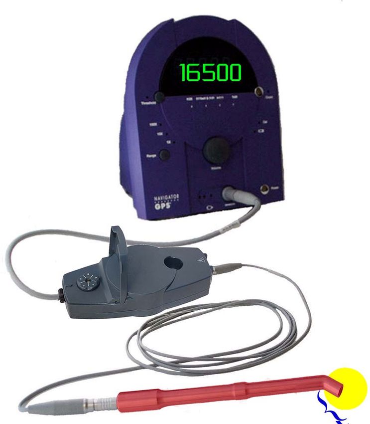
Navigator GPS™ System User Manual

2                                   GP-9200-96-001 R0
                                    Revised 7/22/2014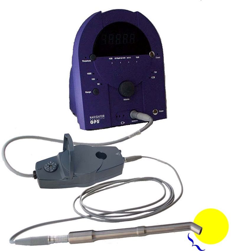
Navigator GPS™ System User Manual

User Manual
1.       Introduction ........................................................................................................... 7
           EC Directives ................................................................................................................................ 8
           Reciprocal Interference.................................................................................................................. 8
           Safety ........................................................................................................................................... 8
           Other ............................................................................................................................................ 8

2.       System Overview and Components .................................................................. 11
     2A. Navigator GPS™ System - Probe Modes .......................................................... 14

3.       Precautions .......................................................................................................... 15

4.       Control Unit, PowerPak, and Co-Pilot ............................................................... 19
     4A. Control Unit........................................................................................................ 19
           SCAN/Calibrate Control ............................................................................................................... 25
           Isotope Control ............................................................................................................................ 25
     4B. PowerPak .......................................................................................................... 26
           Inserting the PowerPak................................................................................................................ 26
           Removing the PowerPak ............................................................................................................. 27
           Charging the PowerPak ............................................................................................................... 27
           Removing the PowerPak Clip ....................................................................................................... 29
     4C. Optional Co-Pilot Device .................................................................................... 29
     4D. Useful Adjustments That Can be Made During Procedures ............................... 32

5.       Cleaning, Disinfection, and Sterile Use of Probes and Probe Cables ............ 33
           3 mm Diameter Cable .................................................................................................................. 33
           6 mm Diameter Cable .................................................................................................................. 33
           6mm Cable.................................................................................................................................. 33
     5A.    Clean/Disinfect Immediately Before Use ............................................................ 34
     5B.    For Dilon Navigator™ 12 mm Probe and Gamma-PET™ Probe only ................ 36
     5C.    Place Probe and Probe Cable in a Sterile Drape ............................................... 37
     5D.    Clean/Disinfect/Store Probe and Probe Cable Immediately After Use................ 37
           Radioactive Decontamination Procedure – OPTIONAL ................................................................. 41
     5E. Clean/Store Control Unit/Gain Module ............................................................... 41

6.       Gain Module and Peak Procedure ..................................................................... 43
     6A. Connecting the Gain Module to the Control Unit ................................................ 43
           Removing the Gain Module .......................................................................................................... 44
     6B. Connecting the Probe to the Gain Module ......................................................... 45
     6C. Running a Peak Procedure ................................................................................ 45
           Dilon Navigator™ 12mm Probe - Technetium-99m isotope - Peak Procedure ................................ 46
           Gamma-PET™ Probe — 511KeV pharmaceutical — Peak Procedure .......................................... 47
           Example - Peak Procedure/Peak Setting for Probe A .................................................................... 48
           Example - Peak Procedure/Peak Setting for Probe B .................................................................... 49

GP-9200-96-001 R0                                                                                                                                                 3
Revised 7/22/2014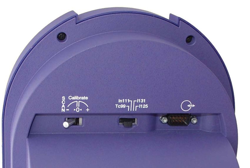
Navigator GPS™ System User Manual

7.       Probe Assembly and Use ................................................................................... 51
     7A.    Dilon Navigator™ 12 mm Probe ........................................................................ 52
     7B.    Gamma-PET™ Probe ........................................................................................ 54
     7C.    Standard Lymphatic Mapping Probe .................................................................. 56
     7D.    Straight Lymphatic Mapping Probe .................................................................... 58
     7E.    Superficial Head and Neck Probe ...................................................................... 60
     7F.    Thoracic Probe .................................................................................................. 62
     7G.    Abdominal Probe ............................................................................................... 64
     7H.    Daniel-Probe™ .................................................................................................. 66

8.       Troubleshooting .................................................................................................. 71

9.       Specifications ...................................................................................................... 73
     9A. Navigator GPS™ Control Unit Specifications ..................................................... 73
     9B. Product Life ....................................................................................................... 74
     9C. System Accuracy ............................................................................................... 74

10. Support Items ...................................................................................................... 75
     10A. Product Ordering Codes and Part Numbers....................................................... 76
     10B. Sterile Drape...................................................................................................... 77

11. Maintenance ........................................................................................................ 79
     11A. Peak Procedure and Verification of Standard Gain ............................................ 79
           Peak Procedure........................................................................................................................... 79
           Verification of Standard Gain ....................................................................................................... 80
           Verification of Calibration Quick Test ............................................................................................ 80

12. Repair ................................................................................................................... 83

13. Recycling ............................................................................................................. 85

14. Limited Warranty ................................................................................................. 87

4                                                                                                                                    GP-9200-96-001 R0
                                                                                                                                     Revised 7/22/2014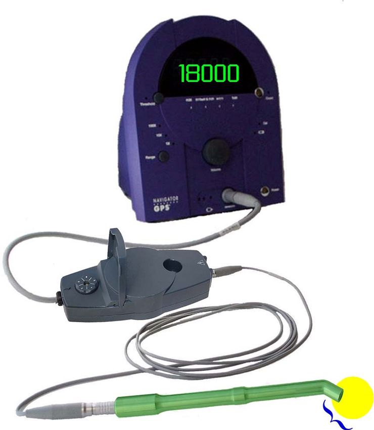
User Manual

GP-9200-96-001 R0                 5
Revised 7/22/2014

Navigator GPS™ System User Manual

6                                   GP-9200-96-001 R0
                                    Revised 7/22/2014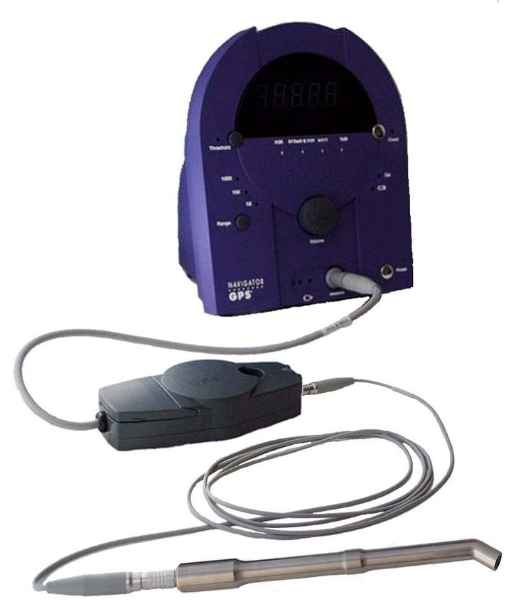
1.       Introduction
Description
The Navigator GPS™ System detects gamma photons, such as are produced by radioactive
decay. The Navigator GPS™ System is a portable, battery powered system.
System use requires the Navigator GPS™ Control Unit: The Control Unit allows the user to adjust
the system's settings and produces a variety of signal outputs. The Control Unit is powered by the
PowerPak (battery).
   •   Navigator GPS ™ Control Unit (“Control Unit”)
   •   PowerPak and Charger
The Control Unit is used with any of eight Navigator™ probe models. The probes differ primarily in
their shape, which the user may prefer for a particular procedure.
   •   Dilon Navigator™ 12 mm Probe
   •   Gamma-PET™ Probe
   •   Standard Lymphatic Mapping Probe (angled tip)
   •   Straight Lymphatic Mapping Probe (straight tip)
   •   Superficial Head and Neck Probe
   •   Abdominal Probe
   •   Thoracic Probe
   •   Daniel-Probe™
The system is supplied non-sterile. This manual includes guidelines for the use of the Probe and
Probe Cable in the sterile field.

Intended Use
For the detection and quantification of gamma radiation from gamma-emitting isotopes in the body
or tissues. Use for non-imaging procedures to measure the amount of radionuclide absorbed by a
particular organ or body region.

Indications for Use
For the detection and quantification of gamma radiation from gamma-emitting isotopes in the body
or tissues. Use for non-imaging procedures to measure the amount of radionuclide absorbed by a
particular organ or body region in open-surgical, laparoscopic or thoracoscopic surgical
procedures.

Manufacture and Distribution
The system is manufactured and distributed by Dilon Technologies. Please direct all inquiries
about the Navigator GPS™ System to Dilon Technologies.

Standards
The Dilon Navigator GPS™ System including Probes and accessories complies with the following
standards:

GP-9200-96-001 R0                                                                               7
Revised 7/22/2014
Navigator GPS™ System User Manual

EC Directives
         EMC Directive 89/336/EEC
         Group l, Class B
         EN 55011
         EMC Directive 89/336/EEC
         IEC 60601-1-2: 3rd Edition
Reciprocal Interference
This product has been tested and verified to ensure that there are no issues or concerns regarding
reciprocal interference. This includes EMI, EMC and RF. This product has been certified and
tested by 3rd party testing facilities. List of standards is as follows:
    •    Medical Electrical Equipment - Part 1: General requirements For Safety 1: Collateral
         Standard: Safety Requirements For Medical Electrical Systems – IEC 60601-1-1: 3rd Ed.
    •    Medical Electrical Equipment - Part 1: General Requirements For Safety - Collateral
         Standard: Electromagnetic Compatibility - Requirements and Tests – IEC 60601-1-2: 3rd
         Ed.
Safety
    •    Medical Electrical Equipment - Part 1: General requirements For Safety 1: Collateral
         Standard: Safety Requirements For Medical Electrical Systems – IEC 60601-1-1: 3rd Ed.
    •    Medical Electrical Equipment - Part 1: General Requirements For Safety - Collateral
         Standard: Electromagnetic Compatibility - Requirements and Tests – IEC 60601-1-2: 3rd
         Ed.
    •    Medical Electrical Equipment - Part 1-6: General Requirements For Safety - Collateral
         Standard: Usability - IEC 60601-1-6: 3rd Ed.
    •    Information supplied by the manufacturer of medical devices- EN 1041:2008
    •    Symbols for use in the labeling of medical devices - EN 980 :2008
    •    CAN/CSA C22.2 No. 60601-1, "Medical Electrical Equipment, Part 1: General
         Requirements for Safety & Essential Performance; issued 2008-02-01 Ed. 2
    •    AS/NZS 3200-1-0, Deviations to IEC 601-1 for Application in Australia and New Zealand
Other

The following are trademarks of Dilon Technologies, Inc.: Dilon Navigator™, Dilon Navigator
GPS™, Navigator GPS™, Dilon Navigator™ 12 mm Probe, Gamma-PET™ Probe, Beta-PET™
Probe, Daniel-Probe™, and Navigator™ when used in context with the above.

          CAUTION
          Federal (USA) law restricts this device to sale and use by, or on the order of, a physician.

8                                                                                GP-9200-96-001 R0
                                                                                 Revised 7/22/2014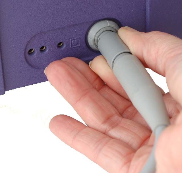
Introduction

Explanation of Symbols
                                      Table 1.   Symbols

                                                           RX only
                                                           Caution: Federal (USA)
                    Type-CF Equipment                      law restricts this device to
                                                           sale and use by, or on the
                                                           order of, a physician.

                    Probe                                  Date of Manufacture

                    Data Port                              Manufactured by

                                                           Consult instructions for
                    Eject
                                                           use

                    Attention, consult
                                                           Temperature limitation
                    accompanying documents

                    Remote Count Control                   Humidity limitation

                    Isotope Control                        Serial number

                    Calibrate Control                      Catalogue number

                                                           European Authorized
                    Fuse
                                                           Representative

                    PowerPak                               Batch code

GP-9200-96-001 R0                                                                       9
Revised 7/22/2014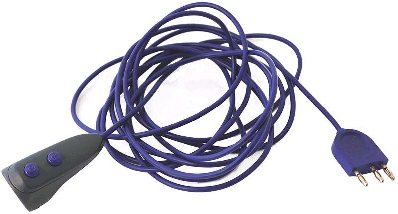
Navigator GPS™ System User Manual

                               Table 1.    Symbols (Continued)

                    PowerPak Low                                    Caution: High Voltage

                    Acceptable shipping/storage conditions: -15° C to 40° C

                    WEEE Symbol (EU only)

10                                                                            GP-9200-96-001 R0
                                                                              Revised 7/22/2014
2. System Overview and Components
Navigator GPS™
Control Unit
PowerPak
Charger
PowerPak
Gain Module Probe
Cable
DILON Navigator™
12mm Probe
Navigator GPS™ Control Unit with Dilon Navigator™ 12 mm Probe
The Navigator GPS™ Control Unit supports several Dilon Probe Models. The illustration shows
each probe model available for use with the system. The Table gives probe model dimensions.
Subsequent sections of this manual describe in detail probe and system use.
GP-9200-96-001 R0 11
Revised 7/22/2014Navigator GPS™ System User Manual
PowerPak
Charger
Navigator GPS™
Control Unit
PowerPak
Probe Cable
Standard Lymphatic
Mapping Probe
Navigator GPS™ Control Unit with Dilon Standard Lymphatic Mapping Probe
12 GP-9200-96-001 R0
Revised 7/22/2014System Overview and Components
Table 2. Probe Dimensions
Probe Tip Tip Shaft Shaft Probe
Diameter Angle Diameter Length Length
Dilon Navigator™ 12 12mm 35 12mm — 242mm
mm Probe
Gamma-PET™ Probe 22mm 0 14mm — 157mm
Standard Lymphatic 14mm 35 6mm 67mm —
Mapping Probe
Straight Lymphatic 14mm 0 6mm 67mm —
Mapping Probe
Superficial Head and 11mm 0 6mm 53mm —
Neck Probe
Abdominal Probe 10mm 0 6mm 190mm —
Thorascopic Probe 10mm 0 6mm 130mm —
Daniel-Probe TM 10mm 30 6mm 190mm —
GP-9200-96-001 R0 13
Revised 7/22/2014System Overview and Components
2A. Navigator GPS™ System - Probe Modes
Dilon Navigator™ 12 mm Probe (page 52)
Cable
Gain Module
Gamma-PET™ Probe (page 54)
Standard Lymphatic Mapping Probe (page 56)
Straight Lymphatic Mapping Probe (page 58)
Superficial Head and Neck Probe (page 60)
DataPak
Abdominal Probe (page 64)
Cable
Thoracic Probe (page 62)
Charger
Daniel-Probe™ (page 66)
GP-9200-96-001 R0 Navigator GPSTM System – Probe Modes 143. Precautions
General
• The output of this system is not to be considered a diagnostic measure of the extent of
disease in the patient, nor the recommended source of therapy.
• Failure to thoroughly review and adhere to the information contained in this User and
Service Manual may pose a potential hazard to the patient and/or user and may void the
warranty
Control Unit, PowerPak, and Charger
• During system use, maintain electrical isolation of the patient. Do not connect either the
probe, the cable, or the internal circuit of the control unit to earth ground, or to other voltage
potentials.
• Maintain patient electrical isolation. Do not defeat the electrical isolation of the probe cable
surface and the control unit housing. These isolate the battery-power circuit inside the
control unit, the conductors inside the probe cable, the probe' surface, and the patient.
• Do not defeat the electrical isolation between the control unit's external DATA PORT and
the inside of the control unit. The external DATA PORT can be connected to earth ground.
Electrical isolation between the DATA PORT and the internal circuit of the control unit
maintains electrical isolation of the patient.
• When optional system components are used with the system, maintain Probe and patient
electrical isolation from earth ground. The optional components include the Co-Pilot Device,
the Gamma Probe drape, and a cart or stand.
• In the operating room, use the Charger at a distance of six feet or greater from the patient.
The charger has a rating in the United States of a "patient proximity charger.”
• Fully charge the PowerPak before use in the system.
• This system is not designed for use in an explosive atmosphere.
• Keep the Control Unit off when changing the PowerPak, and when changing connections
between the Probe, Cable, Control Unit and Gain Module, if used.
• The Control Unit, PowerPak, and Charger are non-sterile. Do not sterilize these
components.
GP-9200-96-001 R0 15
Revised 7/22/2014Navigator GPSTM System User Manual
Probes
Table 3. Precautions
DO NOT put the Probe or Probe Cable in an
autoclave
DO NOT open the Probe.
The Probe is tested and sealed at the factory.
Attempting to open or opening the Probe may
damage the Probe and will void the warranty.
DO NOT drop the Probe.
DO NOT strike the Probe tip against a hard
surface.
The detector element may become damaged. The
Probe may no longer be able to measure radiation.
This may also void the warranty.
DO NOT place probe on or near a magnetic
instrument pad.
16 GP-9200-96-001 R0
Revised 7/22/2014Precautions
Laparoscopic and Thoracoscopic Probe Use
• This user and service manual is designed to assist the use of the Navigator™ system. This
user/service manual is not a reference to surgical techniques. For information on
endoscopic procedures, techniques, complications and hazards please see the books:
Surgical Laparoscopy (Zuker KA ed. St. Louis MO 1991) and Endoscopic Surgery (White
RA Klein SR, Mosby Year Book Inc. St Louis MO 1991).
CAUTION
Endoscopic procedures should be performed only by Physicians having adequate training
and familiarity with endoscopic techniques in addition medical literature should be
consulted relative to techniques, complications and hazards prior to the performance of
endoscopic procedures.
Contraindications
• This device is intended for use only as indicated. It is not intended for use when endoscopic
techniques are generally contraindicated. Please see the book: Textbook of Laparoscopy
(Hulka JF. Grunda and Stratton, inc. Orlando FL 1985 op114-116) for information on
Absolute Contraindications, High-Risk Patients and Low-Risk Patients.
• The use of the Navigator GPS™ system with laparoscopy should only be attempted where
there is adequate visualization of the target tissue.
• Trocars should be placed in accordance with standard laparoscopic and thoracoscopic
techniques with specific regard to target organ geometry to assure probe access to the
target organ. Please reference current Trocar labeling suggesting working knowledge of
laparoscopic techniques and familiarization with trocar placements under direct visualization
through a laparoscope.
GP-9200-96-001 R0 17
Revised 7/22/2014Navigator GPSTM System User Manual
18 GP-9200-96-001 R0
Revised 7/22/20144. Control Unit, PowerPak, and Co-Pilot
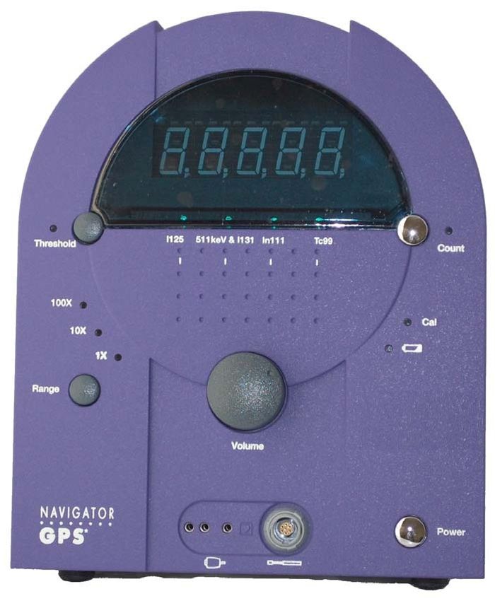
4A. Control Unit
Count Display
Isotope
Indicator
Threshold 10-second
Button and Count Button
Indicators and Indicator
Calibrate
Indicator
Low
Battery
Range Indicator
Button and
Indicators
Volume Power
Button
Co-Pilot Signal Input
Receptacle
The Control Unit contains the display, the PowerPak, and most of the controls. The controls are
located on the front and back of the Control Unit.
The Control Unit allows the user to adjust the system’s settings, and produces signal outputs in the
form of a count rate shown in the display and an audible pitch that represents the intensity of a
Probe’s signal.
The number of gamma photons (called “events”) shown in the Control Unit display is determined
primarily by a Probe and the Probe’s position (with respect to the radioactively tagged tissue), and
secondarily by the position of the controls on the Control Unit.
GP-9200-96-001 R0 Control Unit 19
Revised 7/22/2014Navigator GPSTM System User Manual
Table 4. Controls and Displays on the Front of the Control Unit
Control Display Description
Power Turns on power
Volume Increases/decreases the volume of the audible signal
Display The photon count/second is normally shown. At the end
of a 10-second count, the total photons detected is
shown, then the display returns to showing
counts/second.
Isotope Indicator Indicates the isotope selected.
20 Control Unit GP-9200-96-001 R0
Revised 7/22/2014Control Unit, PowerPak, and Co-Pilot
Table 4. Controls and Displays on the Front of the Control Unit (Continued)
Control Display Description
Range Controls when the audible pitch is heard:
1X – low event rates
10X – medium event rates
100X – high event rates
Pressing the Range button cycles through the ranges; select
the one most useful to the procedure being performed.
NOTE: Range Selection only controls the pitch of the sound
generated by the unit.
Range selection and the corresponding indicators have no
effect on count rates or signal conditioning.
Range Selection has no impact on the performance or counts
displayed by the unit.
Threshold Controls the range of the photon energy detected by the
Probe.
When the Threshold is off, all photon energy, including
scattered photons, are detected. The indicator is not
illuminated.
When the Threshold is on the detection of the scattered
photons is reduced or eliminated. Signals of amplitude
outside the pre-configured energy range are discarded. Only
those events within the particular energy range are counted
and displayed. The indicator is illuminated.
NOTE: The Threshold is normally on when using Probes.
The Threshold may be set to off to count all events seen by a
Probe.
Count Starts a 10-second photon count.
When Count has been pressed, the Count indicator is
illuminated.
When the 10 seconds is complete the Control Unit beeps
and the total count is shown in the display for four seconds.
After giving the total count, the Display goes back to showing
counts per second.
GP-9200-96-001 R0 Control Unit 21
Revised 7/22/2014Navigator GPSTM System User Manual
Table 4. Controls and Displays on the Front of the Control Unit (Continued)
Control Display Description
Cal Probes are used with the SCAN/Calibrate Control in the SCAN
position only. The Calibrate Indicator blinks when the
SCAN/Calibrate Control is in any position other than SCAN.
NOTE: The SCAN/Calibrate Control should be to SCAN for all
uses of all Probes. The SCAN position is the only correct
setting, and when the SCAN/ Calibrate Control is set to SCAN
indicator is not illuminated.
See “Peak Procedure and Verification of Standard Gain” on
page 79 for more information.
Low PowerPak Blinks when the PowerPak charge has only 30 minutes of
useful charge remaining.
Will change to a solid light before the useful charge is
exhausted.
See “PowerPak” on page 26 for more information.
Signal Input Signal Input
For the Dilon Navigator™ 12 mm Probe and the Gamma-
PET™ Probe, connect the Gain Module here.
See “Connecting the Gain Module to the Control Unit” on page
43 for more information.
For Standard Lymphatic Mapping probe, and similar probes,
connects the Probe Cable here. See “6 mm Diameter Cable”
on page 33 for more information.
Co-Pilot Connection for the Co-Pilot accessory.
See “Optional Co-Pilot Device” on page 29 for more
information.
22 Control Unit GP-9200-96-001 R0
Revised 7/22/2014Control Unit, PowerPak, and Co-Pilot
Isotope
Selector
Data
Scan/ Calibrate Port
Control
Manufacturer’s Serial
Fuse Number Label
GP-9200-96-001 R0 Control Unit 23
Revised 7/22/2014Navigator GPSTM System User Manual
Table 5. Controls and Displays on the Back of the Control Unit
Control Display Description
SCAN/Calibrate Set to SCAN/Calibrate when using Probes.
The SCAN position is the only correct position when a Probe is
being used. When set to SCAN, the CAL indicator on the front of
the Control unit will not be illuminated, nor will it flash.
See “SCAN/Calibrate Control” on page 25 for more information.
See also “Peak Procedure and Verification of Standard Gain” on
page 79.
Isotope Selector Selects the Isotope to be detected by the Control Unit.
See “Isotope Control” on page 25 for more information.
Data Port Unused.
24 Control Unit GP-9200-96-001 R0
Revised 7/22/2014Control Unit, PowerPak, and Co-Pilot
SCAN/Calibrate Control
This control should be in the SCAN Position. On some probe models, such as the Standard
Lymphatic Mapping Probe, this control is temporarily placed in other positions during an optional
VERIFICATION procedure
NOTE: The SCAN/Calibrate Control has four positions. Make sure it is set to SCAN prior
to a procedure.
See “Verification of Standard Gain” on page 80 for information on Verification.
NOTE: If the front panel CAL indicator is flashing, move the control to the SCAN position.
SCAN low center high
Isotope Control
The Isotope Control sets the Navigator™ to detect specific isotopes when in use.
CAUTION
It is important that the Isotope Control is set to the isotope that is going to be used in the
procedure. Setting the Isotope Control incorrectly will result in incorrect detection.
Tc99 In111 511keV & I131 I125
GP-9200-96-001 R0 Control Unit 25
Revised 7/22/2014Navigator GPSTM System User Manual
The Isotope Control setting on the back of the Control Unit illuminates the corresponding light on
the Isotope Indicator on the front of the Control Unit.
Only one Isotope Indicator will light up at a time; the above image is for illustrative purposes only
4B. PowerPak
Inserting the PowerPak
PowerPak in place
Front
Side
Right Side Direction of PowerPak
Insert the PowerPak in the opening on the right side of the Control Unit. The notched end of the
PowerPak is inserted first, notched corner on top. The Control Unit will “click” when the PowerPak
is positioned properly.
26 PowerPak GP-9200-96-001 R0
Revised 7/22/2014Control Unit, PowerPak, and Co-Pilot
Removing the PowerPak
Eject
latch
Press the eject latch. The PowerPak will be released and will protrude slightly from the Control
Unit.
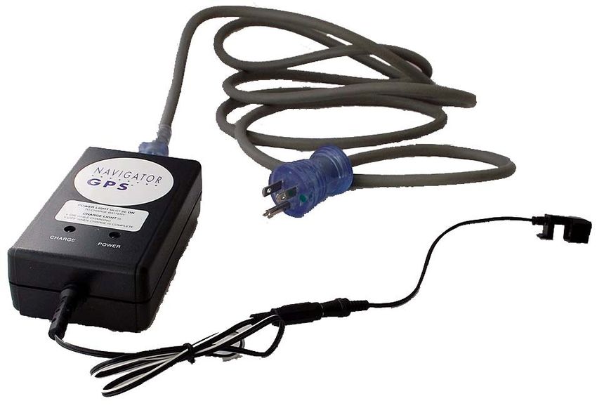
Charging the PowerPak
PowerPak
Charger
PowerPak
Clip
1. Snap the PowerPak Clip onto the PowerPak, cord side up, at the corner of the
PowerPak that has the purple arrow pointing to it. Ensure that the PowerPak Clip
is connected to the Charger cable.
NOTE: There is only one way to snap the PowerPak Clip to the PowerPak.
GP-9200-96-001 R0 PowerPak 27
Revised 7/22/2014Navigator GPSTM System User Manual
2. Plug the Charger into a normal electrical outlet (110-240 VAC, 50-60 Hz).
NOTE: It takes approximately two hours to charge a completely drained PowerPak.
Having a fully charged spare PowerPak is recommended.
The Charger has two indicator lights, Power and Status. Power is green, Status is
yellow.
Table 6. PowerPak Charger Indicator Lights
Indicator Color Condition Meaning
Power green ON Connected to power
Power green OFF Not connected/No power
Status Light yellow ON Charging the PowerPak
Status Light yellow OFF PowerPak absent/fully
charged
NOTE: Use only PowerPaks supplied by Dilon. This PowerPak has the proper dimensions
and a key feature that holds it securely in the Navigator GPS™ control unit.
NOTE: The PowerPak supplied with the Navigator GPS™ System contains lead. If the
PowerPak requires disposal, recycle the PowerPak locally in a manner appropriate
for its lead content.
NOTE: Consider using a second PowerPak. A second PowerPak may be kept in the
Charger while the first PowerPak is being used in the Control Unit.
28 PowerPak GP-9200-96-001 R0
Revised 7/22/2014Control Unit, PowerPak, and Co-Pilot Removing the PowerPak Clip Push the PowerPak Clip off the PowerPak with your thumb. 4C. Optional Co-Pilot Device The optional Co-Pilot Device initiates counting periods and changes the audible range. The Co- Pilot includes two small buttons, and a long, small-diameter cable. The Co-Pilot is clipped onto the end of a Probe, and connected to the Control Unit at the Co-Pilot receptacle. GP-9200-96-001 R0 Optional Co-Pilot Device 29 Revised 7/22/2014
Navigator GPSTM System User Manual

The Co-Pilot is supplied sterile and may be used inside or outside the sterile drape.

                  Count

                                                                     Range

The “C” button is the COUNT button. A one-second count is obtained by pushing and releasing this
button once. A ten-second count is obtained by pushing this button twice, in quick succession. The
total is shown in the DISPLAY on the Control Unit.
The “R” button is the RANGE button. This button operates the Range control on the Control Unit.
Push and release the RANGE button to select an audible range, appropriate to the signal detected
by the system.

30                                   Optional Co-Pilot Device                       GP-9200-96-001 R0
                                                                                    Revised 7/22/2014
Control Unit, PowerPak, and Co-Pilot
Match the spacing of the prongs with the spacing of
the receptacles.
The Co-Pilot is attached to the Control Unit at the Co-Pilot receptacle.
CAUTION
The Co-Pilot can only be attached one way – the prongs are not evenly spaced.
GP-9200-96-001 R0 Optional Co-Pilot Device 31
Revised 7/22/2014Navigator GPSTM System User Manual
4D. Useful Adjustments That Can be Made During Procedures
Threshold
Button/ 10-second
Indicator Button/
Indicator
Range Button/
Indicator Volume
Table 7. Useful Adjustments
Adjustment Benefit
Threshold Increases signal when only a low number of events are observed.
Threshold control is normally ON. When On, the system counts only the
events in a narrow energy range around the signal. Change Threshold to
OFF to allow the system to count all signals it detects.
Range You will be able to hear changes in high event rates. The Range is
normally 1X. In the X10 position, every tenth signal produces an audible
output. In X100, only every one hundredth produces an audible output.
The Range control only affects the sound. The count shown in the display
is independent of the range setting.
10-Second Count Press to obtain a 10-Second count. The total is displayed for at least four
seconds so one may, if desired, record the total.
Volume Adjust to desired loudness.
32 Useful Adjustments That Can be Made During Procedures GP-9200-96-001 R0Cleaning, Disinfection, and Sterile Use of Probes and Probe Cables
5. Cleaning, Disinfection, and Sterile
Use of Probes and Probe Cables
All Probes and Probe Cables require cleaning and disinfection immediately after and immediately
before use.
Follow these steps to ensure that cleaning and disinfection is done correctly:
• “Clean/Disinfect Immediately Before Use” on page 34
• “Place Probe and Probe Cable in a Sterile Drape” on page 37
• “Clean/Disinfect/Store Probe and Probe Cable Immediately After Use” on page 37
• “Radioactive Decontamination Procedure – OPTIONAL” on page 41
• “Clean/Store Control Unit/Gain Module” on page 41
CAUTION
All Probes and Probe Cables are used inside a sterile drape. The Control Unit, Gain
Module (if used), and PowerPak/Charger are used outside the sterile field. Probes and
Probe Cables should be cleaned and disinfected separately from the other components.
Cables
One of two cables is used depending on the Probe.
3 mm Diameter Cable
The Dilon Navigator™ 12 mm Probe and the Gamma-PET™ Probe use a cable that has two
conductors and a cable outside diameter of approximately 3 mm.
The connector is a locking connector. To disconnect the cable from the probe pull on the hood. Do
not pull on the jacket. To disconnect the cable from the Navigator™ Gain Module, pull on the
connector's hood. Do not pull on the connector jacket.
6 mm Diameter Cable
A different cable used for the Standard Lymphatic Mapping Probe, the Straight Lymphatic
Mapping Probe, the Superficial Head and Neck Probe, the Thoracic Probe, the Abdominal Probe,
and the Daniel-Probe™. This cable has five receptacles inside the probe end, and seven pins
inside the plug that connects to the Navigator GPS™ control unit. The cable is approximately 6
mm in diameter.
The connector is a locking connector. To disconnect the cable from the probe pull on the hood. Do
not pull on the jacket. To disconnect the cable from the Navigator GPS™ control unit, pull on the
hood. Do not pull on the jacket.
6mm Cable
6mm Cable - Navigator™ End 6mm Cable - Probe End
GP-9200-96-001 R0 Clean/Disinfect Imediately Before Use 33
Revised 7/22/2014Navigator GPSTM System User Manual
5A. Clean/Disinfect Immediately Before Use
1. Remove Probe and Probe Cable from storage container. Discard container.
2. Visually inspect the Probe and Probe Cable for contamination.
If the probe or cable shows visual signs of contamination—or may possibly be
contaminated—then proceed with Step 3 and Step 4, otherwise go to Step 5.
34 Clean/Disinfect Immediately Before Use GP-9200-96-001 R0
Revised 7/22/2014Cleaning, Disinfection, and Sterile Use of Probes and Probe Cables
3. Wipe all visible contaminants from the Probe and Probe Cable with a clean
sponge moistened with distilled water.
4. Wipe Probe and Probe Cable with a soft cloth soaked in an enzymatic detergent
solution (suitable for surgical instruments) for approximately 30 seconds.
Visually inspect the Probe and Probe Cable for contamination.
Repeat Step 4 until visual inspection shows no contaminated areas.
GP-9200-96-001 R0 Clean/Disinfect Imediately Before Use 35
Revised 7/22/2014Navigator GPSTM System User Manual
5. If the probe tip and cable end show visual signs of contamination—or may
possibly be contaminated—then proceed with this Step 5. Otherwise proceed
with Step 6.
Swirl the covered plug ends of the Probe and Probe Cable in 100ml of enzymatic
detergent solution for 90 seconds.
CAUTION
Do not swirl the plug ends for more than two minutes.
6. Ensure that the connector ends of the Probe and Probe Cable are dry.
7. Connect the Probe to the Probe Cable.
WARNING! Do not scratch or abrade the Probe when decontaminating. Scratching/ abrading
the Probe will make future decontamination more difficult, if not impossible.
5B. For Dilon Navigator™ 12 mm Probe and Gamma-PET™ Probe only
1 Run the Peak Procedure (see page 45). If the Peak Procedure was performed earlier in the
day for the Probe, ensure that the Gain Module dial is in the same Peak Setting.
36 For Dilon Navigator™ 12 mm Probe and Gamma-PET™ Probe only GP-9200-96-001 R0
Revised 7/22/2014Cleaning, Disinfection, and Sterile Use of Probes and Probe Cables
5C. Place Probe and Probe Cable in a Sterile Drape
1. Wipe the Probe and Probe Cable with a soft cloth moistened with ethyl or
isopropyl alcohol (70% concentration).
2. Place the Dilon Navigator™ 12 mm Probe and Probe Cable into a suitable sterile
drape (Spectrum Laboratories Inc., Part Number 719-03883-000 or equivalent).
WARNING! Do not drop the Probe, or strike the Probe tip against a hard surface. Doing so may
damage the detector element, and the Probe may no longer be able to measure
radiation.
3. The Probe and Probe Cable are now ready for use.
Refer to other sections of this manual, start with the section on the specific probe
model.
5D. Clean/Disinfect/Store Probe and Probe Cable Immediately After Use
1 Disconnect Probe Cable from Control Unit (or Gain Module if using).
Put Control Unit (and Gain Module if using) to one side.
GP-9200-96-001 R0 Place Probe and Probe Cable in a Sterile Drape 37Navigator GPSTM System User Manual
2 Disconnect the Cable from the Probe.
OR
38 Clean/Disinfect/Store Probe and Probe Cable Immediately After Use GP-9200-96-001 R0
Revised 7/22/2014Cleaning, Disinfection, and Sterile Use of Probes and Probe Cables
3 Wipe all visible contaminants from the Probe and Probe Cable with a clean sponge
moistened with distilled water.
4 Wipe Probe and Probe Cable with a soft cloth soaked in an enzymatic detergent solution
(suitable for surgical instruments) for approximately 30 seconds.
Visually inspect the Probe and Probe Cable for contamination.
Repeat Step 4 until visual inspection shows no contaminated areas.
GP-9200-96-001 R0 Clean/Disinfect/Store Probe and Probe Cable Immediately After Use 39
Revised 7/22/2014Navigator GPSTM System User Manual
5 If the probe tip and cable end show visual signs of contamination—or may possibly be
contaminated—then proceed with this Step 5. Otherwise proceed with Step 6.
Swirl the covered plug ends of the Probe and Probe Cable in 100ml of enzymatic detergent
solution for 90 seconds.
CAUTION
Do not swirl the plug ends for more than two minutes.
6 Ensure that the connector ends of the Probe and Probe Cable are dry.
CAUTION
Do not contaminate other items by wiping them with used cleaning solution. Dispose of
used cleaning solution properly.
WARNING! Do not scratch or abrade the Probe when decontaminating. Scratching/ abrading
the Probe will make future decontamination more difficult, if not impossible.
40 Clean/Disinfect/Store Probe and Probe Cable Immediately After Use GP-9200-96-001 R0
Revised 7/22/2014Cleaning, Disinfection, and Sterile Use of Probes and Probe Cables
7 When completely dry, loosely coil the Probe Cable (about six coils), and place the Probe
and Probe Cable into a clean plastic bag/container, or other suitable storage container.
8 Store the container in a clean, safe environment.
Radioactive Decontamination Procedure – OPTIONAL
An increase in background counts may signal radioactive contamination of the Probe or the
environment. If a process of elimination shows the Probe to be contaminated with radioactive
material, the Probe must be decontaminated.
1. Decontaminate the Probe using standard Nuclear Medicine department
techniques, which may involve washing the Probe with a solution such as
Radiacwash™.
2. Ensure that all recesses, crevices, and mating surfaces are clean.
3. Dispose of pads and cleaning solution in approved containers.
5E. Clean/Store Control Unit/Gain Module
1. If unclean, wipe Control Unit and Gain Module (if present) with a soft cloth
moistened with mild soap and water. Dry with a soft cloth.
2. Store the Control Unit and Gain Module in a clean, safe environment.
CAUTION
Follow universal, generally accepted practices when handling components that have
come in contact with blood or tissue.
GP-9200-96-001 R0 Clean/Store Control Unit/Gain Module 41
Revised 7/22/2014Navigator GPSTM System User Manual
42 Clean/Store Control Unit/Gain Module GP-9200-96-001 R0
Revised 7/22/20146. Gain Module and Peak Procedure
The Gain Module sits between the Control Unit and the Probe Cable of the Dilon Navigator™ 12
mm Probe or the Gamma-PET™ Probe.
6A. Connecting the Gain Module to the Control Unit
Line up the key on the Gain Module plug with the key on the Control Unit Probe receptacle, and
insert the Gain Module plug into the Probe receptacle on the front of the Control Unit.
Key Key
WARNING! The key on the plug MUST line up with the key on the receptacle. Do not try to jam
the plug into the receptacle; this may damage the cable.
GP-9200-96-001 R0 43
Revised 7/22/2014Navigator GPSTM System User Manual
The plug will “click” when it is seated properly.
Removing the Gain Module
There is a hood at the end of the plug. Grasp the hood and pull straight out until the plug detaches
from the Control Unit.
WARNING! Do not pull on the jacket of the Cable. You must pull on the hood at the very end of
the Cable. Pulling on the jacket may damage the Cable.
Pull Here
Hood
DON’T
Pull Here!
Jacket
44 Connecting the Gain Module to the Control Unit GP-9200-96-001 R0
Revised 7/22/2014Gain Module and Peak Procedure
6B. Connecting the Probe to the Gain Module
Connect the Probe end of the Cable to the Probe.
Connect the Gain Module End of the Cable to the Gain Module.
6C. Running a Peak Procedure
A Peak Procedure finds the best “sensitivity” of a probe - the setting on the Gain Module at which
the Probe counts the most events.
Adjusting the Gain Module Dial increases/decreases the count rate in the Navigator™ Display.
Starting with the dial in the full clockwise position, the location on the Gain Module Dial where the
count rate first reaches a maximum value is called the Peak Setting.
The Probe must be held in a fixed position with respect to an isotope source during a Peak
Procedure. This source can be either a Check Source or the injection site (or some other region of
high activity) of the patient.
Only the Dilon Navigator™ 12 mm Probe and the Gamma-PET™ Probe require a Peak
Procedure, because they are the only probes that use the Gain Module.
EACH Probe –
1. Requires a Peak Procedure;
2. Needs a Peak Procedure run on EACH day-of-use, before the first surgical procedure;
3. Has its own Peak Setting on the Gain Module, which may have its Peak Setting change
slightly day-to-day.
GP-9200-96-001 R0 Connecting the Probe to the Gain Module 45Navigator GPSTM System User Manual
Dilon Navigator™ 12mm Probe - Technetium-99m isotope - Peak Procedure
COUNTS
Increase/decrease
When counts are
Start with a full counter- greatest, Peak Setting
clockwise setting then has been determined;
find the Peak Setting. leave dial at that
setting.
SCAN Tc99
ADJUST
Controls on back
Dial setting
Tc99
Keep position steady
Dilon Navigator tm 12 mm Probe
The Peak Procedure finds Peak Setting for the module's Dial, for that Probe for that day.
1. 99m technetium pharmaceutical is in patient.
2. On Control Unit, Isotope control set to Tc99, and Isotope indicator Tc99 is
illuminated.
3. On Control Unit, SCAN/Calibrate control is set to SCAN.
4. On Control Unit, Threshold is ON, and Threshold Indicator is illuminated.
5. On Module, the Dial is at full counter-clockwise position. (near zero).
6. On Module, increase Dial to the first dial setting that maximizes the counts
shown in the display.
This is the Peak Setting.
NOTE: On the module, the Dial can be set very closely to the Peak Setting for that
Probe for that day.
NOTE: If uncertain about the Peak Setting, achieve it again. Remember the current dial
setting as tentative. Remember the event rate shown in the display. Turn the dial
to maximum, the event rate is typically lower than your tentative setting. Turn the
dial to minimum, the event rate should be lower than your tentative setting. Then
perform Step 6 again and achieve the Peak Setting.
46 Running a Peak Procedure GP-9200-96-001 R0
Revised 7/22/2014Gain Module and Peak Procedure
Gamma-PET™ Probe — 511KeV pharmaceutical — Peak Procedure
COUNTS
Increase/decrease When counts are greatest,
Peak Setting has been
Start with a full counter- determined; leave dial at that
clockwise setting, then setting.
find the Peak Setting.
Controls on back
SCAN 1131
ADJUST
Dial Setting
511keV
Keep position steady
The Peak Procedure finds Peak Setting for the module's Dial, for that Probe for that day.
1. 511 keV pharmaceutical is in patient.
2. On Control Unit, Isotope control set to I131, and Isotope indicator 511keV & I131
is illuminated.
3. On Control Unit, SCAN/Calibrate control is set to SCAN.
4. On Control Unit, Threshold is ON, and Threshold Indicator is illuminated.
5. On Module, the Dial is at full counter-clockwise position. (near zero).
6. On Module, increase Dial to the first dial setting that maximizes the counts
shown in the display.
This is the Peak Setting.
NOTE: On the module, the Dial can be set very closely to the Peak Setting for that
Probe for that day.
NOTE: If uncertain about the Peak Setting, achieve it again. Remember the current dial
setting as tentative. Remember the event rate shown in the display. Turn the dial
to maximum, the event rate is typically lower than your tentative setting. Turn the
dial to minimum, the event rate should be lower than your tentative setting. Then
perform Step 6 again and achieve the Peak Setting.
GP-9200-96-001 R0 Running a Peak Procedure 47
Revised 7/22/2014Navigator GPSTM System User Manual
Example - Peak Procedure/Peak Setting for Probe A
Turn dial
until counts
are highest
Isotope
Keep position steady
A
1. Probe A is going to be used on Monday for surgical procedures.
2. Peak Procedure is run on Probe A, before the first surgical procedure of the day.
3. Probe A counts are highest when the Gain Module dial is set to just above 4.
4. The dial is kept at that location. This is the Peak Setting for that probe.
5. Probe A is now ready for surgical procedures.
6. The dial on the Gain Module is not adjusted for the rest of the day.
48 Running a Peak Procedure GP-9200-96-001 R0
Revised 7/22/2014Gain Module and Peak Procedure
Example - Peak Procedure/Peak Setting for Probe B
Turn dial
until counts
are highest
Isotope
B Keep position steady
1. Probe B is going to be used on Tuesday for surgical procedures.
2. Peak Procedure is run on Probe B, before the first surgical procedure of the day.
3. Probe B counts are highest when the Gain Module dial is set to just above 6.
4. The dial is left at that location. That is the Peak Setting for that probe.
5. Probe B is now ready for surgical procedures.
6. The dial on the Gain Module is not adjusted for the rest of the day.
GP-9200-96-001 R0 Running a Peak Procedure 49
Revised 7/22/2014Navigator GPSTM System User Manual
Table 8. Using Multiple Probes During One Surgical Day
Control Display Description
• Probe A is going to be used on
Wednesday for all surgical
procedures.
• A Peak Procedure is run on
Probe A before the first
surgical procedure of the day.
• Probe A counts are highest
when the Gain Module dial is
set to about 4 1/2. The dial is
left at that location. A
• Probe A is ready for all surgical
procedures.
• Probe A is dropped. It cannot
DO NOT USE
be used again until tested and
disinfected. A
• The Surgical Team chooses to
use Probe B for the rest of the
procedures. B
USE
• A Peak Procedure is run on
Probe B before the next
surgical procedure (or before
continuing the current surgical
procedure).
• Probe B counts are highest
when the dial on the Gain
Module set to just above 6. The
dial is left at that location.
B
• Probe B is ready for the rest of
the surgical procedures.
50 Running a Peak Procedure GP-9200-96-001 R0
Revised 7/22/2014Probe Assembly and Use
7. Probe Assembly and Use
All Probes should be cleaned and disinfected immediately before and immediately after use. See
“Cleaning, Disinfection, and Sterile Use of Probes and Probe Cables” on page 33 for more
information.
Also, the PowerPak should be charged prior to use.
See “PowerPak” on page 26 for more information.
NOTE: A full charge for a discharged PowerPak takes two hours.
GP-9200-96-001 R0 51
Revised 7/22/2014Navigator GPSTM System User Manual
7A. Dilon Navigator™ 12 mm Probe
TM
Navigator
PowerPak
Gain Module
Gain Module Cable
Navigator TM
12mm Probe
The Dilon Navigator™ 12 mm Probe is used in various procedures. A typical sequence of setting
up the Dilon Navigator™ 12 mm Probe for a procedure with a 99mTechnetium isotope (such as
may be used in a lymphatic mapping procedure for a sentinel node) is as follows:
Before Surgery
• Charge and insert the PowerPak into Control Unit (page 26).
• Connect the Probe, Cable, and Gain Module to Control Unit.
• Run a Peak Procedure (page 45). You will see the system as shown above.
• Use Probe and Cable in a Sterile Drape (page 37).
During Surgery
• See also: Useful Adjustments That Can Be Made During Procedures (page 32).
• See also: Optional Co-Pilot Device (page 29).
After Surgery
• See: Cleaning, Disinfection, and Sterile Use of Probes and Probe Cables (page 33).
52 GP-9200-96-001 R0
Revised 7/22/2014Probe Assembly and Use
NOTE: The time to charge a PowerPak by the Charger may take as long as two hours.
NOTE: Keep Control Unit Power off until all components are connected. This helps
preserve component life.
NOTE: A Peak Procedure must be performed before using the Probe in the first surgical
procedure of the day. See page 45.
NOTE: Although the Peak Procedure is typically performed with no sterile drape around
the probe and cable, the Peak Procedure may also be performed with the probe
and cable inside a sterile drape.
NOTE: After a peak procedure has been performed, the control unit and Module settings
are given in the table.
NOTE: Follow the instructions in the section on Cleaning, Disinfection, and Sterile Use of
Probe and Cable.
Table 9. Dilon Navigator™ 12 mm Probe - Settings and Indicators
Control/Indicator Setting
Controls (in back)
Calibrate SCAN
Isotope Tc99
Indicators (in front)
Range 1X
Threshold Illuminated
Display 0
Isotope Tc99
Gain Module
Dial at Peak Setting Perform Peak Procedure on that Probe, that
day
GP-9200-96-001 R0 53
Revised 7/22/2014Navigator GPSTM System User Manual
7B. Gamma-PET™ Probe
Navigator TM
PowerPak
Gain Module
Gain Module Cable
Gamma-
PET™ Probe
The Gamma-PET™ Probe is used in various procedures. A typical sequence of setting up the
Gamma-PET™ Probe for a procedure with pharmaceutical that emits 511 keV Photons -- such as
those that proceed from PET pharmaceuticals, such as 18F-FDG is as follows:
Before Surgery
• Charge and insert the PowerPak into Control Unit (page 26).
• Connect the Probe, Cable, and Gain Module to Control Unit.
• Run a Peak Procedure (page 45). You will see the system as shown above.
• Use Probe and Cable in a Sterile Drape (page 37).
During Surgery
• See also: Useful Adjustments That Can be Made During Procedures (page 32).
• See also: Optional Co-Pilot Device (page 29).
After Surgery
• See: Cleaning, Disinfection, and Sterile Use of Probes and Probe Cables (page 33).
54 GP-9200-96-001 R0
Revised 7/22/2014Probe Assembly and Use
NOTE: The time to charge a PowerPak by the Charger may take as long as two hours.
NOTE: Keep Control Unit Power off until all components are connected. This helps
preserve component life.
NOTE: A Peak Procedure must be performed before using the Gamma-PET™ Probe in
the first surgical procedure of the day. See page 45.
NOTE: Although the Peak Procedure is typically performed with no sterile drape around
the probe and cable, the Peak Procedure may also be performed with the probe
and cable inside a sterile drape.
NOTE: After a peak procedure has been performed, the control unit and Module settings
are given in the table.
NOTE: Follow the instructions in the section on Cleaning, Disinfection, and Sterile Use of
Probe and Cable.
Table 10. Gamma-PET™ Probe - Settings and Indicators
Control/Indicator Setting
Controls (in back)
Calibrate SCAN
Isotope I131 (works for 511)
Indicators (in front)
Range 1X
Threshold Illuminated
Display 0
Isotope 511keV & I131
Gain Module
Perform Peak Procedure on that Probe, that
Dial at Peak Setting
day
GP-9200-96-001 R0 55
Revised 7/22/2014Navigator GPSTM System User Manual
7C. Standard Lymphatic Mapping Probe
TM
Navigator
SCAN/ Calibrate Control
SCAN
Isotope Control
Tc99
Probe Cable
PowerPak
Standard Lymphatic Mapping Probe
The Standard Lymphatic Mapping Probe is used in various procedures. A typical sequence of
setting up the Standard Lymphatic Mapping probe for a procedure with a 99mTechnetium isotope
(such as may be used in a lymphatic mapping procedure for a sentinel node) is as follows:
Before Surgery
• Charge and insert the PowerPak into Control Unit (page 26).
• Connect the Probe, Cable, and Control Unit.
• Set Control Unit rear-Panel SCAN/Calibrate control to SCAN.
• Set Control Unit rear-Panel Isotope control to Tc99.
• Use Probe and Cable in a Sterile Drape (page 37).
During Surgery
• See also: Useful Adjustments That Can be Made During Procedures (page 32).
• See also: Optional Co-Pilot Device (page 29).
After Surgery
• See: Cleaning, Disinfection, and Sterile Use of Probes and Probe Cables (page 33).
56 GP-9200-96-001 R0
Revised 7/22/2014Probe Assembly and Use
NOTE: The time to charge a PowerPak by the Charger may take as long as two hours.
NOTE: Keep Control Unit Power off until all components are connected. This helps
preserve component life.
NOTE: For 99mTechnetium, the Control Unit settings are also given in the attached table.
NOTE: Follow the instructions in the section on Cleaning, Disinfection, and Sterile Use of
Probe and Cable.
Table 11. Standard Lymphatic Mapping Probe - Settings and Indicators
Control/Indicator Setting
Controls (in back)
Calibrate SCAN
Isotope Tc99
Indicators (in front)
Range 1X
Threshold Illuminated
Display 0
Isotope Tc99
GP-9200-96-001 R0 57
Revised 7/22/2014Navigator GPSTM System User Manual
7D. Straight Lymphatic Mapping Probe
TM
Navigator
SCAN/ Calibrate Control
SCAN
Isotope Control
Tc99
Probe Cable
PowerPak
Straight Lymphatic Mapping Probe
The Straight Lymphatic Mapping Probe is used in various procedures. A typical sequence of
setting up the Straight Lymphatic Mapping probe for a procedure with a 99mTechnetium isotope
(such as may be used in a lymphatic mapping procedure for a sentinel node) is as follows:
Before Surgery
• Charge and insert the PowerPak into Control Unit (page 26).
• Connect the Probe, Cable, and Control Unit.
• Set Control Unit rear-Panel SCAN/Calibrate control to SCAN.
• Set Control Unit rear-Panel Isotope control to Tc99.
• Use Probe and Cable in a Sterile Drape (page 37).
During Surgery
• See also: Useful Adjustments That Can Be Made During Procedures (page 32).
• See also: Optional Co-Pilot Device (page 29).
After Surgery
• See: Cleaning, Disinfection, and Sterile Use of Probes and Probe Cables (page 33).
58 GP-9200-96-001 R0
Revised 7/22/2014Probe Assembly and Use
NOTE: The time to charge a PowerPak by the Charger may take as long as two hours.
NOTE: Keep Control Unit Power off until all components are connected. This helps
preserve component life.
NOTE: For 99mTechnetium, the Control Unit settings are also given in the attached table.
NOTE: Follow the instructions in the section on Cleaning, Disinfection, and Sterile Use of
Probe and Cable.
Table 12. Straight Lymphatic Mapping Probe - Settings and Indicators
Control/Indicator Setting
Controls (in back)
Calibrate SCAN
Isotope Tc99
Indicators (in front)
Range 1X
Threshold Illuminated
Display 0
Isotope Tc99
GP-9200-96-001 R0 59
Revised 7/22/2014Navigator GPSTM System User Manual
7E. Superficial Head and Neck Probe
Navigator TM
SCAN/ Calibrate Control
SCAN
Isotope Control
Tc99
Probe Cable
PowerPak
Superficial Head and Neck Probe
The Superficial Head and Neck Probe is used in various procedures. A typical sequence of setting
up the Superficial Head and Neck Probe for a procedure with a 99mTechnetium isotope (such as
may be used in a procedure locating a hyperactive parathyroid gland) is as follows:
Before Surgery
• Charge and insert the PowerPak into Control Unit (page 26).
• Connect the Probe, Cable, and Control Unit.
• Set Control Unit rear-Panel SCAN/Calibrate control to SCAN.
• Set Control Unit rear-Panel Isotope control to Tc99.
• Use Probe and Cable in a Sterile Drape (page 37).
During Surgery
• See also: Useful Adjustments That Can Be Made During Procedures (page 32).
• See also: Optional Co-Pilot Device (page 29).
After Surgery
• See: Cleaning, Disinfection, and Sterile Use of Probes and Probe Cables (page 33).
60 GP-9200-96-001 R0
Revised 7/22/2014You can also read