Cable Drive System Linkage, Horizon & Single Row Sprayers - Parts & Operators Manual - Croplands Equipment
←
→
Page content transcription
If your browser does not render page correctly, please read the page content below
Cable Drive System
     Parts & Operators Manual
             Hydraulic DG

Linkage, Horizon & Single Row Sprayers

                            Manual Part Code : HT-POMCD2012A

                  1
1 : Introduction

Croplands Equipment is a subsidiary of Nufarm Australia Ltd and operates as Croplands Equipment Pty Ltd in
Australia and Croplands Equipment Ltd in New Zealand. Croplands are a leading importer, manufacturer and
supplier of spraying equipment primarily to the New Zealand and Australian markets, with expanding sales into the
USA and Europe. Established in 1972, Croplands is one of the four largest suppliers, with the largest range, of
spraying equipment to the Australasian market.

This manual presumes the Croplands Cable Drive System (CD System) will be used in conjunction with an
agricultural sprayer and does not include information for the chemical spraying operations of your sprayer – for
that see the separate manual and safety information applicable to the sprayer operations.

This system has been manufactured to a high standard for use in Agriculture, Horticulture and related industries,
for operators / contractors big and small.

As the owner of a Croplands Cable Drive System, please read this manual thoroughly to fully familiarise yourself
with all aspects of the safe and correct operation of this system. Maintenance information and useful tips have
been noted so please use these to get the best from your product.

Should you need any support or advice on the set up and use of your Cable Drive System or Croplands sprayer,
contact your local Croplands dealer or contact Croplands Customer Support.

Croplands Dealers are listed on www.croplands.com.au under “dealers” in the menu.

Croplands can be contacted in Australia on 1800 999 162, and in New Zealand on 0800 106 898.

No liability can be accepted for any inaccuracies or omissions in this publication, although due care has been
taken to make it as complete and accurate as possible.

The information, illustrations and technical data were considered to be correct at the time of preparation.

In accordance with our policy of continuous development, Croplands Equipment Pty Ltd reserves the right to
make changes at any time without notice.

                                                               2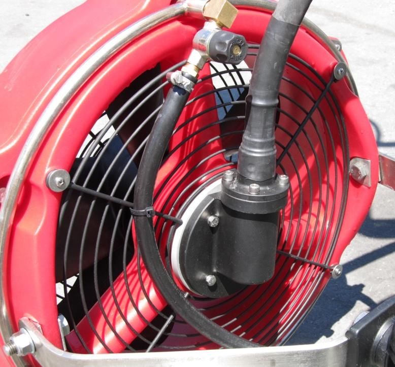
2 : Contents:

 1 : Introduction...................................................................................................................................... 2
 2 : Contents: .......................................................................................................................................... 3
 3 : About Your Warranty ...................................................................................................................... 4
 4 : Warranty Policy ............................................................................................................................... 4
 5 : Conditions of Warranty ................................................................................................................... 5
 6 : Pre Delivery Check List & Warranty Registration ......................................................................... 6
 7 : Safety Information ........................................................................................................................... 7
 8 : Cable Drive Overview ..................................................................................................................... 8
    Cable Drive System - Basics                                                                                                                          8
    Major Components (also see parts & specifications pages)                                                                                             9
    Sprayer Rigging                                                                                                                                    10
 9 : Installation ..................................................................................................................................... 11
    Distribution Gearbox, HP-072-DG55H                                                                                                                 11
    Hydraulic Motor + Soft Start Manifold inc RPM Control                                                                                              12
    Hydraulic Connection to the Tractor                                                                                                                13
    Cable Installation & Rigging                                                                                                                       14
    Cable Installation & Waterproofing                                                                                                                 15
    Straight Cable Connectors, QM-380 or 500                                                                                                           16
    T-Box & Right Angle Box, QM-380 or 500                                                                                                             17
    Cable Joiner                                                                                                                                       18
 10 : Operating Instructions ................................................................................................................. 19
    1 : Connect the hydraulic hoses to the tractor.                                                                                                    19
    2 : Checklist.                                                                                                                                     19
    3 : Engage Power                                                                                                                                   19
    4 : Daily operations                                                                                                                               20
    Troubleshooting                                                                                                                                    20
    Note re Cable Handling                                                                                                                             20
 11 : Lubrication & Maintenance ......................................................................................................... 21
    Maintenance Schedule                                                                                                                               21
    Sealants & Lubricants                                                                                                                              22
    Distribution Gearbox                                                                                                                               22
    Cables : HP-071-125 or 150 or 175 or 200 or 250 or 300 cm                                                                                          23
    Cable Joiner                                                                                                                                       23
    Right Angle & T-Box Connectors                                                                                                                     24
 12 : Parts & Specifications.................................................................................................................. 25
 13 : Croplands Technical Service ....................................................................................................... 28

                                                                              3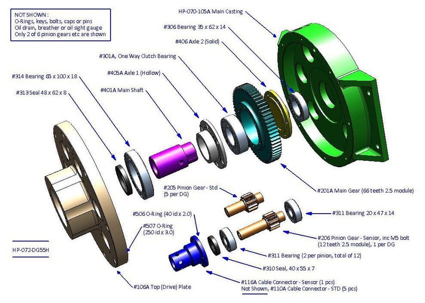
3 : About Your Warranty

 Croplands Equipment Pty Ltd will honour any warranty               Warranty Repair Site
 repair in line with the policy outlined on the following           The warranty provides for repairs to be carried out at the
 page. The following information will assist you in                 servicing dealer’s normal place of business. An owner may
 understanding our warranty procedures.                             elect to have repairs carried out at his own residence, but
                                                                    whilst Croplands will accept the actual repair cost of the failed
 Any authorised Croplands Dealer or service outlet can              component(s), the travelling costs will not be covered under
 perform warranty repairs, however we recommend that                warranty.
 the Dealer or Reseller from whom you bought the
 machine carry out any such repairs.
                                                                    Items Not Covered By Warranty
 Most warranty repairs are handled routinely, but                   The warranty does not allow for the cost of the following
 sometimes requests for repairs cannot be accepted                  items.
 under warranty. Normal wear and tear is not covered by
 warranty nor does warranty apply if a machine fails                These are the responsibility of the owner.
 prematurely and that failure can be attributed to abuse
                                                                          1.   Labour to travel to and from a breakdown or for any
 or neglect.                                                                   distance charges
                                                                          2.   Labour premiums that might apply for any repairs
                                                                               that are made outside the dealer’s normal business
                                                                               hours
 Whilst Croplands will abide by its warranty policy under                 3.   Transportation costs of the machine to and from the
 all genuine circumstances, we must emphasise that such                        service outlet
 can only apply when our equipment has been used in                       4.   Freight costs of the machine to and from the service
 applications for which it was designed and manufactured                       outlet
 and that a reasonable degree of care and common sense                    5.   Telephone or fax calls made by the owner in
                                                                               connection with the repairs
 has been exercised by the operator.

4 : Warranty Policy

Croplands Equipment Pty Ltd (trading as Croplands) warrants to its authorised Dealer, who in turn, warrants to the original purchaser
(Owner) that each new Croplands’ sprayer, part or accessory will be free from proven defects in material and workmanship for twelve (12)
months from the date of delivery to the first Owner according to the conditions outlined. This warranty does not cover damages resulting
from abuse, accidents, alterations, normal wear or failure to maintain or use the Croplands product with due care.

During the warranty period, the authorised Croplands Dealer shall repair or replace, at Croplands option, without charge for parts and labour
any part of the Croplands product, which fails because of defects in material or workmanship. The Owner must provide the authorised
Dealer with prompt written notice of the defect (within 14 days of its occurrence), and allow reasonable time for replacement or repair.
Repair may, at Croplands option, include the replacement of parts with functionally equivalent reconditioned or new parts. Replacement
parts will be warranted for the balance of the original warranty period or for ninety (90) days, whichever is longer. Croplands (at its option)
may request failed parts to be returned to the factory. Any travel time of a service technician and/or transportation of the Croplands product
to the authorised servicing Dealer for warranty work are the responsibility of the Owner.

EXCLUSIVE EFFECT OF WARRANTY AND LIMITATION OF LIABILITY

THIS WARRANTY IS IN LIEU OF ALL WARRANTIES OF MERCHANTABILITY, FITNESS FOR A PURPOSE OR OTHER REPRESENTATIONS,
WARRANTIES OR CONDITIONS, EXPRESSED OR IMPLIED. The remedies of the Owner set forth herein are exclusive. CROPLANDS neither
assumes nor authorises any person to assume for it any other obligation or liability in connection with the sale of covered machines.
Correction of defects, in the manner and for applicable period of time provided above, shall constitute fulfillment of all responsibilities of
CROPLANDS to the Owner, and CROPLANDS shall not be liable for negligence under contract or in any manner with respect to such
machines. IN NO EVENT SHALL THE OWNER BE ENTITLED TO RECOVER FOR INCIDENTAL, SPECIAL OR CONSEQUENTIAL DAMAGES SUCH AS
BUT NOT LIMITED TO, LOSS OF CROPS, LOSS OF PROFITS OR REVENUE, OTHER COMMERCIAL LOSSES, INCONVENIENCE OR COST OF
RENTAL OR REPLACEMENT EQUIPMENT.

                                                                      4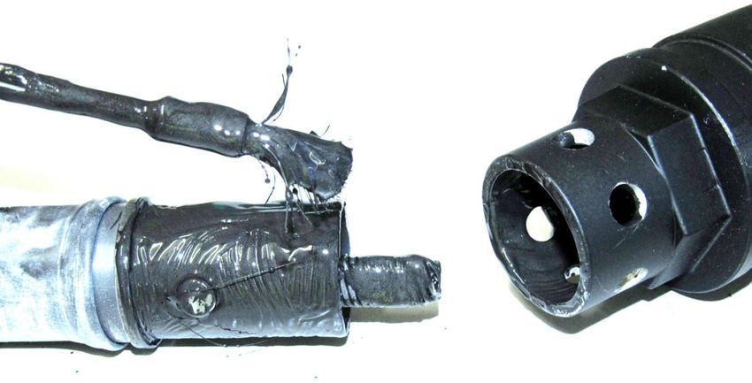
5 : Conditions of Warranty

1.   The warranty is not transferable.
2.   The Warranty Registration Form must be returned to Croplands by the Owner Operator within 14 days of taking delivery
     of the unit. Only when warranty registration is completed and returned, can Croplands fulfill all warranty obligations.
3.   Schedule of components and conditions not covered by warranty are:

                          Failure resulting from neglect, such as improper operation, lack of required maintenance or continued use of
       Abuse
                          the equipment after the discovery of a defect which results in greater damage to the unit.
                          Deteriorated or failed components such as: O-rings, hoses, seals, electrical wiring and connections damaged by
       Environmental      corrosive chemicals, dirt and sand, excessive heat or moisture. Owners should ensure the type and strength of
       Conditions and     chemicals used in the sprayer are compatible with the design of the unit.
       Application        Warranty determination for these types of failures will be made by Croplands only after inspection of failed
                          components. In most instances these will incur inspection charges and cost of replacement parts.
                          Normal wear and consumable items such as: oils and lubricants, diaphragms, filter elements, flowmeters,
       Normal Wear        clutches, fan belts, drive belts, pivot pins, paint, light bulbs and nozzles are considered to be normal wear items
                          and are not warranted.
                          Component failure caused by not performing scheduled maintenance service such as: oils, grease, failure to
       Maintenance        clean tanks, pumps, filters, spray lines, nozzles or any other blocked components. Not tightening or replacing
                          loose or missing bolts, nuts, fittings, shields and covers.
                          Damages or machine failure caused by carelessness or accidental damage, improper operation, excessive
       Damage
                          speed during travel and operation, inappropriate transportation or storage of the sprayer or attachment.
                          Failures due to faulty or inadequate electrical sources of power. Owners who use their own 12 volt power
       Power Source
                          source must make sure that it is suitable for operating the spraying equipment.
                          Any unauthorised alteration, modification, attachments or unauthorised repairs to the Croplands sprayer or
       Alterations
                          attachments. Written approval must be obtained from Croplands for any such items to maintain warranty.
                          The time taken to remove and re-install a warranted part or component into other brands of sprayers will not
       Removal &
                          be covered by Croplands warranty. Only parts and labour directly attributable to the repair of the Croplands
       Installation
                          unit is covered.
                          Croplands do not pay for cleaning the sprayer, parts, accessories or work area before or after the warranty
       Clean-up Time      repair. Clean-up time is affected primarily by the application or conditions in which the sprayer is operated and
                          maintained. Since clean-up time can be so variable, cleaning time should be considered a customer expense.
                          Warranty does not cover transportation or insurance costs for sprayers or other equipment needing repair or
       Transportation     re placement of warranted components. Nor does it cover any freight or insurance costs in obtaining new parts
                          or returning old parts to Croplands for inspection purposes.
                          Warranty does not cover time required to diagnose a warranty problem. Diagnostic time is affected greatly by
       Costs              the training and expertise of the technician employed to do the job. With proper training of service personnel,
                          diagnostic time should be at a minimum.
                          Croplands expects that Dealers will assign a well trained and proficient technician to handle any warranty
       Diagnostic Time    repairs. Since Croplands is not in control of either of these responsibilities, we elect not to cover diagnostic
                          time.
       Non-Genuine        Use of parts other than Croplands parts for repair of warranted parts will automatically negate any warranty.
       Parts              Warranted components must be replaced with genuine Croplands repair parts.
       Unauthorised       Repairs by an unauthorised agent will automatically forfeit any warranty. An authorised Croplands Dealer must
       Repairs            carry out warranty repairs.

                                                                    5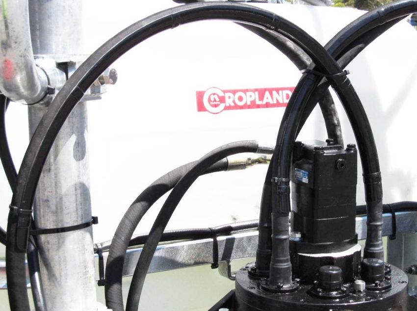
6 : Pre Delivery Check List & Warranty Registration
Warranty Policy: The Warranty Registration Form must be returned to Croplands by the Owner Operator within 14 days
of taking delivery of the unit. Only when warranty registration is completed and returned, can Croplands fulfill all warranty
obligations. This form must be completed and signed by both Owner and Dealer, and a copy returned by the Dealer to
Croplands. (Dealer and customer should keep a copy).
OWNER NAME DEALER NAME
Address Address
Phone & email Phone & email
Signature of Owner Signature of Dealer Representative
Date Purchased: Serial Number: (if applicable)
Tick Each box to affirm completion
Tick Each box to affirm completion
Operator manuals supplied: Cable Connections (DG, T-Box, 90 deg, Straight):
- Parts & Operator Manual (this manual) - All cables connected & secure
- Sprayer Operators Manual (if applicable) - All connections have Silicon Sleeves fitted
Distribution Gearbox & Motor: Flexible cables:
- Undamaged - Undamaged
- Oil visible in sight glass (or fill as required) - Radius guides fitted (if applicable)
- Hydraulic Motor fitted - Cables within radius criteria & free to move
- Hydraulic Control Manifold fitted
- RPM control valve fitted (Manual or Electric ?) Check Operations:
- Hydraulic hose fitted (1/2” pressure) - Cables running freely & correct fan rotation
- Hydraulic hose fitted (3/4” return line) - Soft start is operational
- No oil leaks - RPM control is working (manual or electric)
Important: By executing this Checklist / Warranty Certificate:
1. The Owner:
(a) Agrees that all operators must read the Operator’s Manual before using the Cable Drive System / Sprayer and follow all the procedures
in the manual for the use of the Cable Drive System, and will exercise due care in the use of the system;
(b) Agrees that Croplands’ liability for any loss or damage suffered by the owner in connection with the owner’s use of the Cable Drive
System is limited to the cost of repair or replacement of the unit;
(c) Agrees that the owner will bear any loss the owner suffers as a consequence of any failure by the owner to comply with 1(a);
(d) Acknowledges that the owner is trained and is fully responsible for the safe and correct operation of the system;
(e) Agrees that the owner will fully train any person who is required to operate the CD System / Sprayer, as to how to operate the unit in a
safe and correct manner.
2. The Dealer: Undertakes that it has met the obligations of installation, service and warranty start up.
6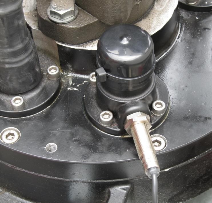
7 : Safety Information
Safety must be an Integral Part of Chemical Farming Operations,
Not Just an After Thought
Rules for Cable Drive Operation:
Always read your Cable Drive System’s operator manual thoroughly before operating. Accidents occur every year
because of careless use of farm chemicals and farm machinery. You can avoid these hazards by observing these safety
instructions.
Check the complete system, but in particular the hydraulic hose and flexible cable connections, prior to each use, for
any loose connections, and any leaks. These precautions can prevent injury to personnel and damage to equipment.
Always wear appropriate protective gloves when tightening connections. Damaged, loose or worn connections could
result in operator being exposed to substances which could result in illness or faulty operation.
Use only genuine Croplands parts for any necessary replacement. All parts are important to the equipment design.
Homemade parts may look the same but could be dangerous in operation.
Always replace warning decals when damaged and make certain operator understands proper safety practices.
Do not disconnect any hydraulic components while the system is in operation. Always relieve system (hydraulic)
pressures before doing any work on the machine. Disconnecting components while under pressure will result in
uncontrolled spray discharge, which may be hazardous to humans.
Do not disconnect any mechanical cable drive components while the system is in operation. This precaution can
prevent injury to personnel and damage to equipment.
Do not operate the cable drive system whilst at the same time folding sprayer boom arms. This precaution can
prevent injury to personnel and damage to equipment.
Keep unit under cover to prolong the life, and safe operation of all components.
Failure to follow these instructions may result in serious injury or death!
Caution Decals
7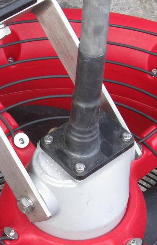
8 : Cable Drive Overview
Cable Drive System - Basics
Simplicity
The Croplands Cable Drive System has been
designed as an easy to understand, easy to
install and easy to maintain system for
powering the Croplands Quantum Mist (QM)
spray heads.
In essence, each Quantum Mist head is driven
via a flexible cable shaft.
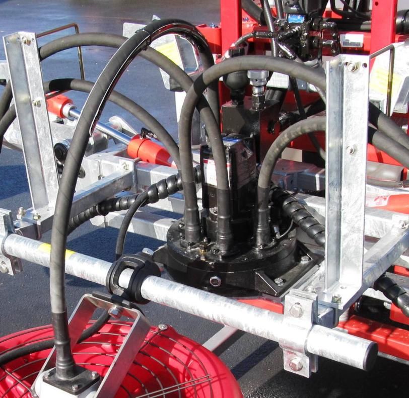
Drive Unit
Using tractor hydraulics, a hydraulic motor (fitted with soft start &
rpm control manifold) is used to power the 6 outlet Distribution
Gearbox (DG) which drives the (up to 6) individual flexible cable
shafts.
At the opposite end, the cable simply plugs into, and drives each
spray head, via:
… Straight Connector (SC) (shown below right),
… T-Box (TB), or
… Right Angle Drive (RA) (shown below).
Cables
Flexible Drive Shaft (Cable)
technology is well proven
over many years, and is often
used in the aviation, military
and automotive industries.
The Croplands system uses a
specially wound, high
strength 12mm steel cable
running in a heavy duty steel & rubber protective casing.
The cable connections use a very simple lock button. Rotational
power is transmitted via the square ends which plug into the DG
drive pinions & spray head connectors (T-Box, Right Angle or Straight
Connectors).
8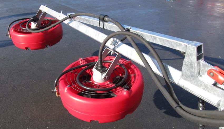
Overview
Major Components (also see parts & specifications pages)
Sprayer Components
The Croplands Cable Drive System is easy to install,
modular system for powering the Quantum Mist
(QM) spray heads. It is adaptable to a wide range or
sprayers. Simply mix and match the required
components, changing cable lengths as required.
Quantum Mist Heads (QM-500 or QM-380).
It is not recommended to retrofit an old
spray head – either replace with a new head
or replace the main body assembly with a
cable drive version.
Cables, Six different lengths
HP-071-125 or 150 or 175 or 200 or 250 or 300 cm
(1.25 ~ 3.0 metres).
Silicon Sleeves, HP-070-526
MUST be used on every cable connection ….
(for waterproofing).
Cable Radius Guides, HP-070-001 or 001A
Cable Joiner, HP-071-CJ1
Used to join two cables, (as shown)
Distribution Gearbox, HP-072-DG55H (6 outlet, hydraulic drive. Gear ratio 1 : 5.5)
Hydraulic Motor, OMR-8032
Soft Start Manifold, HP-070-004 which incorporates a manual rpm control valve.
Spray Head Connector – Straight, HP-073-380 and HP-073-500 (This is the default connector)
Spray Head Connector – T Box, HP-074-380 (shown) and HP-074-500
Spray Head Connector – Right Angle, HP-075-380 and HP-075-500
Additional Options
RPM Sensor, UP-402A. (Requires sprayer to be fitted with HV4000 or Digiblock).
Electric speed control, HP-070-004-2. (Requires sprayer to be fitted with HV4000).
Distribution Gearbox require a mounting bracket specific to each sprayer.
9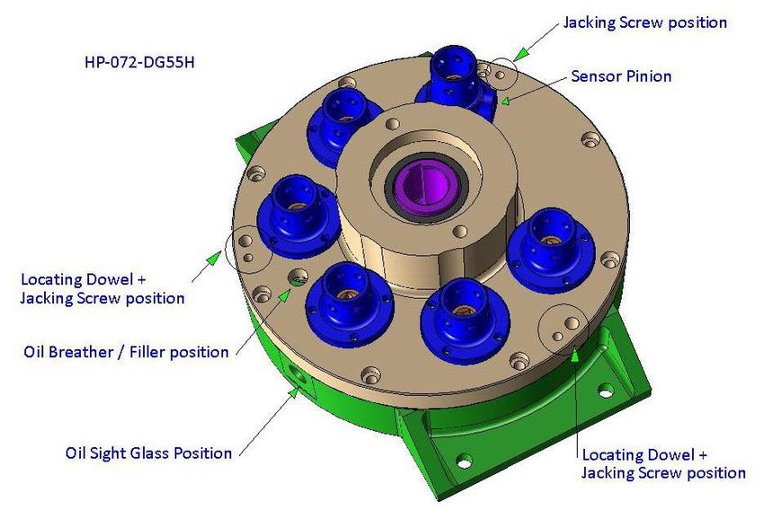
Overview

Sprayer Rigging

  For optimal cable life it’s very important the
  cables are routed in a manner that
  maintains generous radius bends. The
  minimum allowed radius is 240mm. For this
  reason it’s best to rig each sprayer in a
  manner that uses the correct cable length –
  not too long or too short. The choice of
  connection at the spray head can also
  influence the cable selection. Adjusting the
  head positions may require a change of
  cable length.

  The default choice is the “Straight”
  connector because it’s the simplest, lightest,
  quietest and cheapest. The RA drive is a
  neat option for top & bottom or left & right                                   FRP Cable Radius Guide
  fans. T-Boxes can also be used to drive (no
  more than) 2 spray heads in series.                        These brackets better support the cables weight and helps maintain the
                                                             minimum cable radius. Also an aid to cable positioning when boom is folding.

  It’s important to allow cables some freedom of movement. Excessive heat and wear will result from securing
  cables into rigid positions.

  Shown are some scematic examples of cable rigging for
  sprayers (only right hand side shown). There are many
  choices to suit differing applications.

    Preferred option for Horizon 5 boom.
    RA drive on outer heads is required if the boom is to be folded.
    See example below (Joiner is yet to be correctly mounted).

                                                                                         Preferred option for 4 head grape sprayer. RA
                                                                                         drive on lower heads makes for “cleaner” rigging.

                                                                   10
9 : Installation
Distribution Gearbox, HP-072-DG55H
Components
The Distribution Gearbox (DG), HP-072-DG55H is
End Cap, HP-070-524 (with cable tie)
the core component in the Cable Drive System.
The following items are (occasionally) fitted to, or
required for the DG.
OMR8032 (Hydraulic Motor)
HP-070-004 (Manifold – fitted to motor)
HP-070-524 (End Caps)
UP-402A (RPM Sensor) (or M12 x 1 plug)
Castrol EPX85W/140 (Oil)
Flexible Drive Cables .... as required
Mounting plate (sprayer specific)
M12 x 35 bolts + washers (2 pcs)
Loctite 515 sealant (not required is assembled) Use RPM Sensor UP-402A,
Molykote P-74 (or equivalent) or cap with plug.
Installation
Check for oil. In some instances (due to shipping regulations) the DG might come supplied without oil.
Oil to use is Castrol EPX85W/140 or alternatives e.g. Mobil 85W140Plus.
With the correct amount of oil, about 225 ml, it shows as half full in the sight gauge window.
Mount Hydraulic Motor to the DG (requires 2 @ M12 x 35 bolts). Don’t forget the keyway.
In order to prevent rusting (& then seizure), always use liberal amounts of grease Molykote P-74
(or equivalent) on the motor & DG shafts and surrounding areas.
Always apply a smear of Loctite 515 Flange Sealant (or equivalent) to the mating faces, (must be
watertight seal).
Install RPM Sensor (if required). If not required, cap or plug this hole (M12 x 1 threaded).
Mount the DG assembly to Grease & Seal
appropriate mounting plate Motor Installation
(varies from sprayer to
sprayer).
Install cables as required. All
cable connections must be
well greased and sealed via
Silicon Sleeve etc.
See separate instructions for
Flexible Drive Cable
installation. Breather
Sight gauge
Also see Lubrication & Maintenance information.
Drain (in base)
11Installation
Hydraulic Motor + Soft Start Manifold inc RPM Control
Components / Installation
Powering the Distribution Gearbox is an 80cc hydraulic motor with 32mm shaft (OMR8032). Specially
designed for long life, low rpm, high torque and smooth running. Mount via M8 x 35mm bolts.
Controlling the hydraulic motor is the Soft Start Manifold (HP-070-004), which also incorporates a
manual rpm control valve. Requires M10
x 90 Cap head screws + washers.
Connecting the manifold to the tractor is
RPM Module
Manual RPM Module
via appropriate length hoses.
Connect ½”pressure hose to P.
Connect ¾” return hose to T.
The Distribution Gearbox features a one
way clutch bearing; hence if the oil flow
is incorrect (i.e hoses connected incorrectly), OMR8032
the fans will not turn.
DG, motor, control manifold & fittings
are coated in a black epoxy paint for
improved corrosion protection (manifold
not painted in this picture).
Optional : Operators requiring an “in the
tractor cab” rpm display can do so via two
means – both require the installation of the
UP-402A rpm sensor (see previous page).
The simplest method is to connect this
sensor to the via the Arag Digiblock2
(part A467060L) (see separate manual for ¾” Return ½”Pressure
operating the Digiblock2).
For operators already using the RPM Sensor position
Croplands HV4000 rate controller, rpm capped in this picture
display can be configured as one of the
readout options. (see separate manual for operating the HV4000).
Optional : For operators who wish to control the
rpm from the cab, via the Croplands HV4000
controller, can do so by replacing the manual rpm
control valve with the HP-070-004-2 electric rpm
control valve. The UP-402A rpm sensor is also
required. (see separate manual for operating the
HV4000).
Also see Lubrication & Maintenance information.
12Installation
Hydraulic Connection to the Tractor
It’s important to correctly set up the hydraulic supply from the tractor. This
includes the ¾” return fitting supplied with your Cable Drive system (as a part
of the hydraulic hose kit). This is the DIRECT BACK-TO-TANK fitting required to
Ensure all hydraulic connectors
ensure there is no back-pressure on the oil return from the Cable Drive System. are clean prior to connection,
Check with your dealer to make sure this is carried out in a manner that will not otherwise damage to the
create any warranty issues from incorrect set up. A small charge may be hydraulic system may occur.
incurred for this procedure.
Fit (or ask the dealer to fit) the ¾” female
return coupler direct back-to-tank.
Decide on the best supply remote on
your tractor to use for oil supply to the
Cable Drive System.
Plug the ½” oil supply line coupling to
your selected tractor remote.
Hook up the ¾” return line to the
tractor.
Make certain all hydraulic lines have
enough slack for turning or lifting
operations, and ensure they are well
clear of all tractor working parts –
especially the PTO.
T P
13Installation
Cable Installation & Rigging
Always install a cable with smooth flowing curves ....... or straight lines.
Minimum radius is 240mm.
Use the HP-070-001 fibreglass (FRP) Cable
Radius Guide to support the cables. These
guides are supplied as a 180 degree arc
but can be cut to any required length. All 4 cables (2 cables are using
Never “clip” the fibreglass cable radius radius guides) are loosely (Bungee)
guide over the Silicon Sleeve at the cable supported in just one position.
connection ends (as this will damage the
Silicon Sleeve). FRP Guide starts above
the silicon sleeve
The 120 degree arc, HP-070-001A
moulded polypropylene Cable Radius
Guide has been developed for attachment
over the Silicon Sleeves. Radius Guide (full 180 degree)
Be cautious of wherever cables exit the spray heads – it’s very easy for the
weight of the cable, or angle of the head, or contact with the fan support
bracket etc to create an excessively tight radius / kink just past the
connection.
The cables need to move around (even if slightly) to avoid wearing in the same place.
Whilst it’s very tempting to neatly cable tie the cable
into a permanent placement..... don’t do it !!!!.
Never rigidly fasten the complete cable to the structure. Limit
the number of tie downs to 2 per cable, ideally none. Where
the cable needs to be located in a specific place, use P-Clamps
rather than cable ties etc.
Also see Overview < Sprayer Rigging > plus Lubrication & Maintenance information.
14Installation
Cable Installation & Waterproofing
It’s VITAL to make each connection waterproof.
Always protect each connection with a Silicon Sleeve(HP-070-526). And to prevent rusting (& then seizure),
always use liberal amounts of grease (such as Molykote P74) on the connecting components.
(1) Add Silicon Sleeve (HP-070-526)
Use talcum powder as the
“lubricant” to help slide the
sleeve onto the cable. Do
not use soapy water or oils.
Use Molykote P-74 grease or
(2) Roll back sleeve
Castrol SBX-2 grease, or
Loctite Nickel Based Anti-
seize .... or equivalents.
(3) Add grease to
these 3 areas.
(4) Assemble & pull / roll Silicon Sleeve back over the connection
15Installation
Straight Cable Connectors, QM-380 or 500
Components / Installation
The Straight Cable Connectors are very simple to install.
Cheap, simple & reliable.
Straight cable connector castings are supplied with the
appropriate adaptor components to fit either the QM-500 or
the QM-380. The required adaptor components are
different; hence there are different part codes.
HP-073-380 (for QM-380)
HP-073-500 (for QM-500)
It is VITAL that all connections are waterproof.
Every Connector casting uses an O-ring on the flange.
Always apply a smear of Loctite 515 Flange Sealant (or
equivalent) to the mating faces.
Always protect each cable connection with the (HP-070-
526) Silicon Sleeve (see Cable info).
In order to prevent rusting (& then seizure), always use
liberal amounts of grease Molykote P-74 (or equivalent) on
the cable connecting components.
Use Loctite on QM-380 adaptor
For QM-380 spray heads, the cable drive straight
connector system can only be fitted QM-380 cable drive
heads, connection is via a simple screw in adaptor. NOTE,
the adaptor thread is left handed – must use Loctite 569
(or equivalent).
QM-500 shaft adaptor
.
For QM-500 spray heads, the cable drive straight
connector system can be fitted to any QM-500
head via is via a shaft adaptor (with keyway).
It is not recommended to retrofit older (used) QM-
500 spray heads. Replacement bodies (HP-219-9E)
are available for this purpose.
16Installation
T-Box & Right Angle Box, QM-380 or 500
Components / Installation
Both the T-Box or Right Angle drives are supplied with
the appropriate adaptor components to fit either the
QM-500 or the QM-380. The required adaptor
components are different; hence there are different part
codes.
HP-074-380 (T-Box for QM-380)
HP-074-500 (T-Box for QM-500)
HP-075-380 (RA drive for QM-380)
HP-075-500 (RA drive for QM-500)
It is VITAL that all connections are waterproof.
Every Connector casting uses an O-ring on the flange.
Always apply a smear of Loctite 515 Flange Sealant (or
equivalent) to the mating faces.
Always protect each cable connection with the (HP-
070-526) Silicon Sleeve (see Cable info).
In order to prevent rusting (& then seizure), always use
liberal amounts of grease Molykote P-74 (or equivalent) on the cable connecting components.
Use Loctite on QM-380 adaptor
thread For QM-380 spray heads, the T-Box or RA drives
can only be fitted to QM-380 Cable Drive heads.
Connection via a simple screw in adaptor. NOTE,
the adaptor thread is left handed – must use
Loctite 569 (or equivalent).
QM-500 adaptor plate & shaft
For QM-500 spray heads, the T-Box or RA drives
can be fitted to all existing spray heads. To do this
requires an adaptor plate and drive shaft adaptor
(with keyway).
It is not recommended to retrofit older (used) QM-
500 spray heads. Replacement bodies (HP-219-9E)
are available for this purpose.
17Installation
T-Box
Generally the T-Box is used to combine the last 2 spray heads on a
sprayer’s boom arm, and often with a Right Angle box at the
outermost spray head. This is a very neat configuration.
Adaptor components are identical to the Right Angle drives.
Do not use any more than 2 heads in series.
The T-Box is directional – follow the arrow on the casting.
Cable Joiner 67mm P-Clamp with cable tie each side to
prevent Joiner falling through clamp.
Components / Installation
Cable Joiner, HP-071-CJ1
Used to join 2 cables together to build a
longer cable, e.g. joining 3.0m & 2.5m
cables to create a 5.5m cable.
Very simple to install, simply plug
each cable into the joiner.
Often the joiner is in a position that needs support, if so, ideally support in a manner that
allows some movement (e.g. 67mm P-Clamp).
It is VITAL that all connections are waterproof.
Always protect each
cable connection with
the (HP-070-526) Silicon
Sleeve.
This side shown without In order to prevent
the Silicon Sleeve rusting (& then seizure),
always use liberal
amounts of grease
Molykote P-74 (or
equivalent) on the cable
Silicon Sleeve
connecting components.
1810 : Operating Instructions
1 : Connect the hydraulic hoses to the tractor.
The larger (3/4”) RETURN hose must be fitted to the ¾”
hydraulic fitting supplied and fed directly back to tank.
The pressure line is the smaller diameter hydraulic hose
with a (1/2”) male hydraulic fitting on the end.
This is connected to the remote of your choice and is
the main oil supply from the tractor.
Make certain all hydraulic lines have enough slack for
turning or lifting operations, and ensure they are well
clear of all tractor working parts – especially the PTO.
2 : Checklist.
Always connect & disconnect
Check the DG has sufficient oil. the ¾” RETURN hose FIRST,
otherwise damage to the
Check all cable connections have silicon sleeves. hydraulic system may occur.
Check that all spare DG outlets have caps (and cable tied).
Check electric rpm control valve (if fitted) is connected, and powered.
Check the rpm sensor is correctly installed & connected – or plugged (if not fitted).
Check position of the heads are as required for spraying. Adjust as required.
Check that all cables are free to move (tied in no more than 2 places).
Check that none of the cable radius guides are cutting into the silicon sleeves.
Check that cables don’t have excessively tight bends (240mm radius is minimum).
3 : Engage Power
Engage the hydraulic remote lever in the cab that relates to the
Manual RPM
remote you are using for the CD hydraulic oil supply.
adjustment
The fans will start slowly and after about 5 seconds be up to full
operational rpm (this is the soft start in operation).
Run up slowly. Check all heads are turning & check operating rpm
range. Check that operational rpm can be achieved (required rpm
range will vary with fan size and different crops & canopies).
Adjust fan rpm via the manual rpm (screw down for increased
rpm) or via HV4000 controller.
To achieve maximum fan rpm, ensure the tractor is operating at
the recommended RPM to achieve the required flow / pressure
from the tractor.
19Operating Instructions
4 : Daily operations
Do not insulate the hydraulic motor, soft start manifold or distribution gearbox. These items require air
circulation to operate at acceptable operating temperatures.
Maximum recommended Cable Drive System and fan speed = 3,000 rpm.
Normal (default) maximum rpm are set at: QM-380 is set for 2,600 rpm & QM-500 is set for 2,200 rpm.
This will vary from application to application.
Normal oil flow requirements at the above defaults, for 4 heads, are 32 ~ 38 L/Min at 1200 ~ 2000 psi.
If the Cable Drive System is being operated on a foldable boom arm, do not fold the boom arm with the
fans in use as in almost all cases the act of folding a boom arm will induce overly tight bends in the cable.
Troubleshooting
The cable drive system is very simple, with little to go wrong, and if it does, it’s very easy to diagnose or repair.
If the fans fail to turn, check the
hydraulic hose connections
Cable breakages will occur due to the following causes ....
and oil supply. If this is OK the
problem might be with the one Seizure of the Quantum Mist head’s bearings or seals.
way clutch bearing (which
allows fan over-run when the Seizure of the Right Angle / T-Box gears or bearings.
system is shut down) in the
Overly aggressive start-up (if the soft start accumulator fails).
Distribution Gearbox.
If an individual fan isn’t Avoid these, and the cables will last for ages (the cables just
turning, check the cable ends don’t break in day to day operations).
are properly engaged. If this is
OK, check the cable (see info box for reasons).
If the rpm sensor isn’t working – check the wiring looms and sensor installation (the sensor face must be
set approximately 2mm from the DG drive pinion screw head).
If when engaging the hydraulic power, the fans start instantly to full rpm, stop – and consult technical
support. Possibly it’s a failed pressure accumulator (rare, but can happen), and there is no soft start.
Note re Cable Handling
When handling cables, be very careful when
disconnecting the lower end because this will risk
“zebra striping” your clothes as the cable slides
out. Worse still, if the cable falls onto something
like a sandy soil the cable will then need cleaning
& re-greasing before further use.
TIP : When disconnecting, always plug with end
caps. This makes handling so much easier.
Supplied with each system are several end caps
(available as spare part HP-070-525).
2011 : Lubrication & Maintenance
Maintenance Schedule
With proper installation, care and maintenance, the Cable Drive System should give hundreds, perhaps thousands
of hours of reliable service. However poor installation and maintenance will contribute to early failure.
Care
Keep clean. Suggest applying Lanotec when new to make washing down easier.
As with everything mechanical, the kinder the operator is to the equipment (i.e soft start & soft stop),
the longer it will last.
Repair any problems as soon as they are found. Perform regular scheduled maintenance checks.
Remember – appropriate care and maintenance is also a condition of the warrantee.
Maintenance Schedule
Check DG Oil Check Silicon Sleeves / Check hydraulic Check all fans are
Daily Operations
Level, (sight gauge) waterproofing system for leaks turning
After 50 hours First Distribution Gearbox (DG) Oil Change
Every 200 hours or Rotate cables to Grease in Right
Change DG Oil Re-grease Cables
Yearly / as required new lock position Angle or T-Box
Maintenance Summary
Distribution Gearbox.
Regularly check the condition of waterproofing (Flange sealing, Silicon Sleeves and any plugs or
caps on gear outlets).
Regularly check for any oil leaks – check oil level on a daily basis.
Suggested maintenance is to (first) change the oil after 50 hours (running in), then yearly or
more frequently (say every 200 hours) with heavy usage.
Hydraulics.
Regularly check the condition of all hydraulic hoses and fittings for wear or leaks.
Cables.
Regularly (at least every day the sprayer is being operated) check the condition of the Silicon Sleeves.
Cables should be greased at least once every year, more frequently with heavy usage. Always
wipe off old grease before applying new.
As cables can develop a memory, and to avoid wearing in one place only (on the bends), the
lifespan can be improved by regularly rotating the casing. Our dimple lock feature will allow
rotating a cable by 60 degrees at a time.
T-Box & Right Angle Drive.
Regularly check the condition of waterproofing (Flange sealing & Silicon Sleeves).
Apply 1 pump of grease (via grease nipple) per 200 hours of operation or as a minimum, once
per year as a part of regular scheduled maintenance.
21Lubrication & Maintenance
Sealants & Lubricants
Always apply a smear of Loctite 515 Flange Sealant (or equivalent) to the mating faces.
QM-380 spray head adaptor thread is left handed – must use Loctite 569 (or equivalent).
It is VITAL the Cable Connections are waterproof.
Always protect each connection
with the (HP-070-526) Silicon
Sleeve.
Always replace any damaged
silicon sleeves.
In order to prevent rusting (&
then seizure), always use liberal
amounts of grease on all steel
ferrules & square drive ends.
Use SBX-2 grease or
equivalents such as Molykote
P-74 or Loctite Nickel Based
Anti-seize grease.
Cable lubrication is via Castrol SBX-2 grease.
The T-Box etc helical gear sets are greased with Castrol LMX or Mobil XPH-222 on assembly.
Distribution Gearbox uses 225 ml (it shows as half full in the sight gauge window) of Castrol EPX85W/140 or
alternatives such as Mobil 85W140 Plus.
Distribution Gearbox
Distribution Gearboxes come supplied with oil sight gauge, breather and drain plug (in the base).
To fill, do so by removing the breather. It will take some time for the level to appear in the oil window.
In some instances the DG might come supplied without oil (due to freight shipping regulations).
Oil to use is Castrol
EPX85W/140 or
alternatives such as Mobil
85W140 Plus.
With the correct amount
of oil, about 225 ml, it
shows as half full in the
sight gauge window.
Maintenance is to (first)
change the oil after 50
hours (running in), then
yearly or more frequently
with heavy usage.
Breather Sight gauge
Drain (in base)
22Lubrication & Maintenance
Cables : HP-071-125 or 150 or 175 or 200 or 250 or 300 cm
NOTE : Damaged inner cables (which are available as individual spare parts)
can be replaced assuming the outer casing is not excessively worn.
Replace any cable casing that has been damaged / kinked / crushed, as this will cause a severe wear
point on the inner cable. This is a likely scenario is if the cable has been run over by a vehicle etc.
Cable lubrication is via Castrol SBX-2 grease. Suggested maintenance is to grease each cable yearly,
more frequently with heavy usage. Always wipe off old grease before applying new.
As cables can develop a memory, and to avoid wearing in one place only (on the bends), the lifespan
can be improved by regularly rotating the casing. Our dimple lock feature will allow cables to be
clipped into 6 different holes, hence rotating a cable by 60 degrees at a time is quite possible.
All steel ferrules & square drive ends should be lubricated with SBX-2 grease or equivalents such as
Molykote P-74 or Loctite Nickel Based Anti-seize grease.
o Always protect each connection with the (HP-070-526) Silicon Sleeve
o Always replace any damaged silicon sleeves.
o In order to
prevent rusting
(& then seizure),
always use liberal
amounts of
grease on the
connecting
components.
Cable Joiner
The (sealed) internal shaft is lubricated with Castrol LMX or Mobil XPH-222 grease. The shaft
incorporates a pair of sealed for life bearings. There’s no need for further maintenance.
All connections & square drive ends should be lubricated with SBX-2 grease or equivalents such as
Molykote P-74 or Loctite Nickel Based Anti-seize grease
o Always protect each connection with the (HP-070-526) Silicon Sleeve
o Always replace any damaged silicon sleeves.
o In order to prevent rusting (& then seizure), always use liberal amounts of grease on the
connecting components.
23Lubrication & Maintenance
Right Angle & T-Box Connectors
NOTE : Replacement gears are not available as spare parts – it is more cost effective to purchase a
complete new unit (because helical gears & bearings need to replaced together as a matched sets).
All Right Angle & T-Box connectors use sealed for life bearings. There is no need for further (bearing)
maintenance.
The helical gear sets are greased (with Castrol LMX or Mobil XPH-222) on assembly. Apply 1 pump of
grease (via grease nipple) per 200 hours of operation or per year as a part of regular maintenance.
o Always protect each connection
with the (HP-070-526) Silicon
Sleeve.
o Always replace any damaged
silicon sleeves.
o In order to prevent rusting (& then
seizure), always use liberal
amounts of grease (SBX-2 grease
or equivalents such as Molykote
P-74 or Loctite Nickel Based Anti-
seize grease) on all connecting
components.
Grease nipple positions
2412 : Parts & Specifications
Key Specifications
Distribution Gearbox, gear ratio is 1 : 5.5
System (output) rated to maximum of 3,000 rpm hence maximum recommended (hydraulic motor)
input speed of 545 rpm
Hydraulic Motor, M+S 80cc with 32mm keyway shaft, with SAE A (2 bolt) mounting and rated to
maximum continuous 65 L/min flow @ 3,340 psi.
“Normal” tractor oil flow requirements are 32 ~ 38 L/Min at 1200 ~ 2000 psi.
Oils & lubricants : See Lubrication & Maintenance pages.
Flexible Drive Shafts.
Made in Switzerland by a supplier to the aviation
industry.
The 12mm steel drive cable is wound in multiple
layers to suit required direction of rotation.
Each end of the drive cable is pressure formed into a
10.2mm square x 40mm long drive shaft. The squared end
slides into the DG Pinion drive, fan shaft or adaptor.
Couldn’t be simpler.
The cable runs inside a 26mm Outer Casing, which
comprises of a 16mm ID spiral steel core covered with a
wire braid, then a neoprene “hose” which in turn is
protected via an outer nylon wrap. Very rugged.
The casings terminates in a dimple lock (circled) ferrule at
each end that plugs and clips into the cable connection
castings. The casing + ferrule is 50mm shorter than the
cable.
Sizes available, (weights for complete unit).
1.25 metre (part HP-071-125), 2.0 kg (spare cable inner HP-071-125-1)
1.50 metre (part HP-071-150), 2.4kg (spare cable inner HP-071-150-1)
1.75 metre (part HP-071-175), 2.8kg (spare cable inner HP-071-175-1)
2.00 metre (part HP-071-200), 3.2kg (spare cable inner HP-071-200-1)
2.50 metre (part HP-071-250), 3.8kg (spare cable inner HP-071-250-1)
3.00 metre (part HP-071-300), 4.6kg (spare cable inner HP-071-300-1)
Cable Joiner is a non serviceable component, (no spare parts available), 0.5 kg
T-Box’s (2.0kg), Right Angle Drives (1.5kg) and Straight Connectors (0.5kg) are all non serviceable
items, however the adaptor components, O-rings & connector casting are available as spares.
OMR8032 (Hydraulic motor) is a non serviceable component, (no spare parts available), 10 kg
HP-070-004 (OMR8032 Soft Start Manifold) is a non serviceable item, however the RPM Valves and
Pressure Accumulator are available as spares (see Tech Support).
Hydraulic Hose Kits (from manifold to tractor) are available as spares (part HP-298C-2F (for a Linkage
sprayer)).
25Parts & Specifications
Distribution Gearbox, HP-072-DG55H
Weight = 20 kg
Mounting = 320mm x 120mm for 12mm bolts.
To disassemble (after draining the oil). Remove the 8 x
M8 screws holding both major castings together, and
use 3 of these in the Jack Screw position to push the
two halves apart. The internals are very simple.
Note :
When assembling the DG, always be careful that the one way clutch
bearing (HP-070-301A) is installed the correct way around (make a
careful note when pulling apart the original). All screws (not shown
below) holding the Main Gear assembly together (parts 406, 201A,
301A & 405A) must use Loctite 262 or equivalent.
If ever the gears are badly worn, they should all be replaced (making
it cheaper to buy a new gearbox), and hence only the bearings and
seals, connectors etc are considered as serviceable items.
26Parts & Specifications
Straight Connectors, Right Angle Connectors & T-Box Connectors
These items are not serviceable items. Only the
connector & adaptors are available as spare parts.
Different adaptors are required for QM-380 vs QM-500
spray heads. Different adaptors are required for Straight
Connectors vs Right Angle and T-Box.
The Right Angle & T-Box feature helical cut gears for
optimum strength, low noise & reliability.
HP-073-380 (Straight connector for QM-380), includes adaptor HP-070-604
HP-073-500 (Straight connector for QM-500), includes adaptor parts HP-070-603, 508 & 509
HP-073-380 Kit
inc adaptor
HP-073-500 Kit inc adaptor parts
HP-074-380 (T-Box for QM-380), includes adaptor HP-070-602 # 601
HP-074-500 (T-Box for QM-500), includes adaptor parts HP-070-600, 601 & 509
HP-075-380 (RA drive for QM-380), includes adaptor HP-070-602 # 600A
HP-075-500 (RA drive for QM-500), includes adaptor HP-070-600, 601 & 509
Adaptors HP-070-600A & 601 +
Woodroofe key are used with
QM-500 Right Angle & T-Box
# 602
Connectors HP-070-108
are available as spares
Cable Joiner
Joiner is not a serviceable Adaptor HP-070-602 is
item. used with QM-380 Right
Angle & T-Box
27Parts & Specifications
Hydraulic & Other Components
HP-070-004-2 Electric
(RPM) Control Valve
(12V)
OMR8032
Hydraulic Motor
HP-070-004 Soft Start Control Block,
inc manual (RPM) control valve
HP-070-001A Cable Radius Guide
(trim length to suit)
HP-070-526 Silicon Sleeves
(dusted with talc)
No picture available for Hydraulic Hose Kit
13 : Croplands Technical Service
1300 650 724
Croplands Australia:
Freecall 1800 999 162
Freefax 1800 623 778
sales@croplands.com.au
www.croplands.com.au
28You can also read