Instructions and Maintenance Manual - Movable Mid-Rise Scissor Lift - Manufacturer: Capital Automotive Equipment
←
→
Page content transcription
If your browser does not render page correctly, please read the page content below
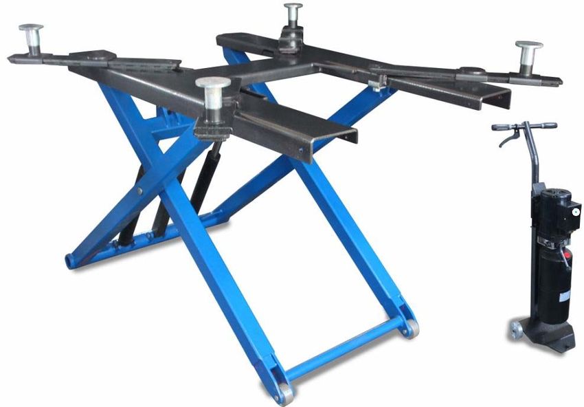
Instructions and Maintenance Manual

                        Movable Mid-Rise Scissor Lift

Manufacturer:
Add:
Website:

       The specifications stated on this brochure are not binding. We reserve the right to change
the specification without notice

                                                0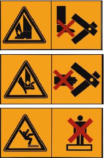
Disclaimer

No part of this book shall be reproduced, stored in retrieval, or transmitted by any means,
electronic, mechanical, photocopying, recording, or otherwise without the written permission of
Manufacturer. While every precaution has been taken in the preparation of this manual, the
publisher assumes no responsibility for errors or omissions. Neither is any liability assumed for
damages resulting from the use of information contained herein.
This document is the proprietary information of Manufacturer. Furnished for customer use only.
No other uses are authorized without written permission from Manufacturer.
Manufacturer reserves the right to make changes, without notice to this document and the products
are describe Manufacturer. or it’s distributors shall not be liable for technical or editorial errors or
omissions made herein; nor for incidental or consequential damages resulting from the furnishing
performances, or use of this document.
This manual contains information that is correct to the best knowledge of Manufacturer. It is
intended to be a guide and should not be considered as a sole source of technical instruction. It
should not replace good technical judgment since all possible situations cannot be anticipated. If
there is any doubt as to the exact installation, configuration, and/or use, please call Manufacturer
or its distributor.
The choice of system component is the responsibility of the buyer, and how they are used cannot
be the liability of Manufacturer. or its distributors. Assembly, installation, commissioning, initial
adjustment and testing, or any work relating to EXTRAORDINARY maintenance, repair,
overhauls, transport and dismantling of the Lift must be performed by specialist personnel from
the authorized to commission, install and dismantle Lifts.
The manufacturer and its distributors decline all responsibility for injury to persons or damage to
vehicles or objects when any of the above mentioned operations have been performed by
unauthorized personnel or when the rack has been subject to abuse.
This manual explains the operational and safety aspects that may prove useful to the Operator and
Maintenance personnel. It will give a better understanding of the structure and operation of the
Lift and the best use of the Lift. The operator should familiarize himself with the technical and
safety aspects of the Lift to be competent in operating the Lift.
  The words “Operator” and “Maintenance Fitter” used in this manual are construed as follows:
         OPERATOR: person authorized to use the Lift. The Lift must be operated in the correct manner as
         indicated
  MAINTENANCE FITTER: person authorized for routine maintenance of the Lift.

  The end user can only use the Lift in the correct manner to which it is intended as defined in the
  instructions.
  Loose clothing should not be worn when operating the Lift. Any personnel with long hair
  operating the Lift should use a protection cap as precautionary safety measures.

                                                   1
******* IMPORTANT NOTE ********
The following must be observed at all times to ensure correct use of the hoist.
Follow regular maintenance schedule as per manual
Ensure safety precautions are taken and use the hoist in accordance with the manufactures
instructions
It is the Owner’s responsibility to ensure all safety regulations and work cover
requirements are met to satisfy all state laws
2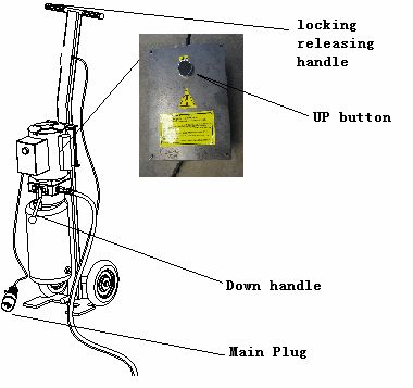
Index
PACKING, TRANSPORT AND STORAGE ......................................................................................................... 5
PACKING................................................................................................................................................................. 5
TRANSPORTATION .............................................................................................................................................. 5
STORAGE................................................................................................................................................................ 5
STACKING .............................................................................................................................................................. 5
UNPACKING........................................................................................................................................................... 5
      WARNING INTRODUCTION ....................................................................................................................... 5
LIFT SAFETY ......................................................................................................................................................... 5
Environment............................................................................................................................................................. 6
ENVIROMENT PROTECTION............................................................................................................................ 6
CHAPTER 1 – LIFT DESCRIPTION................................................................................................................... 7
1.1 FIXED STRUCTURE (FIG.3)............................................................................................................................. 7
1.2 MOVING UNITS (SEE FIG.3) ........................................................................................................................... 7
1.3 LIFT UNIT (SEE FIG.5)...................................................................................................................................... 7
1.4 HYDRAULIC POWER UNIT (FIG.4)................................................................................................................ 7
1.5 CONTROL BOX (FIG.5) .................................................................................................................................. 8
1.6 SAFETY DEVICE............................................................................................................................................... 8
CHAPTER TWO - TECHNICAL SPECIFICATIONS ....................................................................................... 9
2 .1 POWER DEVICE............................................................................................................................................. 9
         2.1.1 ELECTRIC PRINCIPLE DIAGRAM AND ACCESSORIES ................................................... 9
2.2      HYDRAULIC SYSTTEM..................................................................................................................... 10
         2.2.1      PRINCIPLE DIAGRAM AND ACCESSORIES ................................................................ 10
         2.2.2 HYDRAULIC ASSEMBLY ......................................................................................................... 10
         2.2.3 HYDRAULIC OIL RECOMMENDED...................................................................................... 10
2.4 LIFTING WEIGHT ........................................................................................................................................... 11
2.5 MAXIMUM DIMENSIONS OF VEHICLES TO BE LIFTED........................................................................ 11
CHAPTER 3 – SAFETY ....................................................................................................................................... 13
3.1 GENERAL PRECAUTIONS ............................................................................................................................ 14
3.2 RISKS OF ELECTRIC SHOCK ....................................................................................................................... 14
3.3 RISKS AND PROTECTION DEVICES........................................................................................................... 14
3.4 LONGITUDINAL AND LATERAL MOVEMENT ......................................................................................... 14
3.5 RISKS WHILE THE VEHICLE IS BEING RAISED ...................................................................................... 15
3.6 RISKS TO PERSONELL ............................................................................................................................... 15
         3.6.1 RISK OF CRUSHING (OPEARATOR) ..................................................................................... 15
         3.6.2 RISK OF VEHICLE FALLING FROM LIFT........................................................................... 15
         3.6.3 SLIPPING ..................................................................................................................................... 15
         3.6.4 RISK OF ELECTRIC SHOCK ................................................................................................... 16
         3.6.5 RISK RELATED TO INAPPROPRIATE LIGHTING. ............................................................ 16
         3.6.6 RISK OF COMPONENT FAILURE DURING OPERATION................................................. 16
         3.6.7 RISK RELATED TO IMPROPER USE..................................................................................... 16
CHAPTER 4 - INSTALLATION ......................................................................................................................... 17
4.1      INSTALLATION REQUIREMENTS.................................................................................................. 17
4.2      INSTALLATION ................................................................................................................................... 17
4.3 TEST AND CHECK TO PERFORM BEFORE START-UP ....................................................................... 17
         4.3.1 MECHANIAL TESTS.................................................................................................................. 17
         4.3.2      ELECTRIC TESTS ............................................................................................................... 17

                                                                                  3
4.3.3 OPERATING OF THE FOLLOWING DEVICES ............................................................. 17
4.3.4 HYDRAULIC OIL TEST...................................................................................................... 17
4.3.5 ROTATION DIRECTION TEST ......................................................................................... 18
4.4 SET UP ................................................................................................................................................... 18
4.4.1 POSTS ASSEMBLEING.............................................................................................................. 18
CHAPTER 5 OPERATION AND USE............................................................................................................. 19
5.1 CONMANDS .................................................................................................................................................... 19
5.1.1 UP BUTTON ................................................................................................................................. 19
5.1.2 DOWN HANDLE ......................................................................................................................... 19
5.1.3 LOCK RELEASING HANDLE .................................................................................................. 19
5.2.1 LIFTING ....................................................................................................................................... 19
5.2.2 PARKIGN...................................................................................................................................... 19
5.2.3 LOWERING ................................................................................................................................. 19
CHAPTER 6 MAINTENANCE ........................................................................................................................... 20
6.1 PRECAUTIONS................................................................................................................................................ 20
6.2 PERIODIC MAINTENANCE........................................................................................................................ 20
6.2.1 OPERATION FREQUENCY ...................................................................................................... 20
6.2.2 EVERY MONTH .......................................................................................................................... 21
6.2.3 EVERY 6-MONTHS..................................................................................................................... 21
6.2.4 EVERY 12-MONTHS................................................................................................................... 21
CHAPTER 7 - TROUBLESHOOTING .............................................................................................................. 20
7.1 TROUBLESHOOTING GUIDE ....................................................................................................................... 20
7.2 TROUBLESHOOTING CHECKLIST.................................................................................................... 20
CHAPTER 8 SAFETY PICTOGRAMS ON THE LIFT ................................................................................ 21
a) DIGEST OF INSTRUCTIONS............................................................................................................. 21
b) Labels on the machine ........................................................................................................................... 24
CHAPTER 8 EC Declaration of Conformity ................................................................................................... 25
CHAPTER 9 - STRUCTURE AND ACCESSORIES......................................................................................... 26
APPENDIX A-SPECIAL NOTES ........................................................................................................................ 29
A.1 DISPOSAL OF USED OIL ............................................................................................................................ 30
A.2 MACHINE DEMOLITION........................................................................................................................... 30
APPENDIX B-SPARE PARTS ............................................................................................................................. 30
B.1 SPARE PARTS ................................................................................................................................................ 30
B.2 PROCEDURE FOR ORDERING SPARE PARTS...................................................................................... 30
4PACKING, TRANSPORT AND STORAGE
ALL PACKING, LIFTING, HANDLING, TRANSPORT AND UNPACKING OPERATIONS
ARE TO BE PERFORMED EXCLUSIVELY BY EXPERT PERSONNEL WITH KNOWLEDGE
OF THE LIFT AND THE CONTENTS OF THIS MANUAL.
PACKING
The Lift is shipped disassembled into the following parts Weight (kg)
1. Complete vehicle body including frame and rams 340kg
2. Motor and pump assembly and accessory package. 20kg
GROSS WEIGHT 385kg
TRANSPORTATION
The PACKAGE may be lifted and moved with a lift truck (Fig.1) or crane (Fig.2). If either of the latter two is
used, crates must be harnessed with at least 2 slings.
360kg
Fig.1 Fig.2
The equipment chosen must be suitable for safe lifting and moving, bearing in mind the dimensions and weight.
STORAGE
Packed boxes must be kept in a covered, protected place, at a temperature between -10°C - +40°C.
They must not be exposed to direct sunlight or rain.
STACKING
The type of packaging allows the lifts to be stacked up to 5 crates high. Crates may be stacked one
upon the other on trucks if properly positioned and provided they are restrained to prevent falling.
UNPACKING
Check that the lift has not been damaged during transport and that all parts listed are present. The
crates must be opened using precautionary measures to avoid damaging the lift or its parts. Ensure
that parts do not fall from the crate whilst opening.
WARNING INTRODUCTION
This manual has been prepared for workshop personnel and technicians responsible for routine
maintenance. It must be read prior to carrying out any operation with the lift. It contains important
information regarding the personal safety of operator and maintenance workers as well as lift
safety.
LIFT SAFETY
2700kg: The rated load is 2700kg. Do not allow the lift load weight to exceed 2700kg.
5This symbol conveys the attention that should be taken for electrical hazards.
Environment
Environment must be clean and in orderly conditions. In
particular, hazardous areas must be duly delimited.
Any oil or grease on the floor shall be removed
immediately to prevent any risk of slipping or falling.
No object (e.g. work tools and materials) shall be left on the machine
(or in places where these may interfere with its mechanical
movements) nor kept in places where they may fall and hence cause
accidents.
Do not clean nor touch any mechanical part while in motion.
The use of loose-fitting working cloths (e.g. scarves, button-down shirts, etc.)
can be hazardous. Always wear close-fitting garments.
PRESERVING THE MANUAL
The manual is an integral part of the Lift, which should always accompany the lift, even if the unit
is sold. The manual must be kept in the vicinity of the Lift in an easily accessible place so that the
operator and maintenance staff are able to locate and consult the manual at any time.
IT IS HIGHLY RECOMMENDED TO CAREFULLY READ CHAPTER 3, WHICH CONTAINS
IMPORTANT INFORMATION AND SAFETY WARNINGS.
ENVIROMENT PROTECTION
Recycle unwanted materials instead of disposing of them as waste, all tools,
accessories and packaging should be sorted, taken to a recycling center
and disposed of in a manner which is compatible with the environment.
When the product becomes completely unserviceable and requires disposal,
drain off and fluids (if applicable) into approved containers and dispose of
thee product and the fluids according to local regulations.
6CHAPTER 1 – LIFT DESCRIPTION
The hydraulic moveable lift can operate on flat ground or the grade of a slope, less than or equal
to 3º.
The lift consists of the following main parts:
1. Fixed structure (frame)
2. Moving units (idle wheel and hydraulic vehicle)
3. Lift units (2 hydraulic cylinders + power unit)
4. Control station
5. Safety devices
Fig.3 illustrates the various parts of the lift.
Fig.3 Complete unit
1.1 FIXED STRUCTURE (FIG.3)
The frame and the arms are all combined with steel plates, which are the base components of the
moveable lift.
1.2 MOVING UNITS (SEE FIG.3)
Each unit consists of:
Six idle wheels. Four are mounted on the base angle of the frame arms; the other two (slightly
larger) are mounted on the bottom of the movable hydraulic vehicle. A connection - a pin shaft
between the movable vehicle and the underside beam of the frame.
1.3 LIFT UNIT (SEE FIG.5)
Consists of:
1. Two hydraulic cylinders, to lift the frame.
2. One hydraulic unit (see Fig.5), mounted on the mobile trolley.
1.4 HYDRAULIC POWER UNIT (FIG.4)
The hydraulic power unit consists of:
1. An electric motor
2. A geared hydraulic pump
3. Descent hand-valve equipped with a manual oil drain valve (see use and maintenance
7chapter)
4. A adjusting pressure valve
5. Two oil cylinders
6. Oil tanks
7. Two steel flexible pipes to deliver oil
Note: The pressure of the oil delivery pipe may be not less than 40Mpa
1.5 CONTROL BOX (FIG.5)
The panel that houses the electric control box contains the following:
1. Power supply plug
2. UP push button
Note: the other control such as DOWN handle and Lock Releasing handle is equipped at the
hydraulic station.
Fig.4 hydraulic system Fig.5 safety device
1.6 SAFETY DEVICE
The safety devices include:
1. Arms locking system
2. Explosion valve
These safety devices will be described in further detail in the following chapters.
Important note:
The mechanical lock is safety device for preventing hazards resulting from falling of lift due to
cylinder failure. Carefully patient shall be paid with it, especially, it is not allowed to
permanently deformation be happened. Check it carefully before operation and make sure its
function well.
8CHAPTER TWO - TECHNICAL SPECIFICATIONS
Capacity 2700kg
Car max lifting height 1200mm
Lift min stand height 120mm
The frame width 1082mm
The total length 1685mm
Rise time 30 sec
Descent time 30 sec
Gross weight 385kg
Net weight 360kg
Noise pressure level About 70dB (A) 4dB uncertain at 1m away from
machine and 1.6 height, EN ISO 11202 and EN ISO
3746 applied
Operating temperature -10~50℃
Work environment Flat ground or grade of < 3°
Relative humility 90% at 20℃
2 .1 POWER DEVICE
2.1.1 ELECTRIC PRINCIPLE DIAGRAM AND ACCESSORIES
SB START SWITCH QF1/QF2 Breaker T Transformer
KM ALTERNATING M ELECTRIC MOTOR
CONTACTOR
92.2 HYDRAULIC SYSTTEM
2.2.1 PRINCIPLE DIAGRAM AND ACCESSORIES
2.2.2 HYDRAULIC ASSEMBLY
(1,2) Oil cylinder and anti-broken valve
(3) Descending valve
(4) Pressure limit valve
(5) Flow adjusting valve
(6) Retaining valve /Throttle valve
(7) Pump station
(8) Electrical motor
(9) Oil filter
(10) Oil Tank
(11) Anti leakage valve
2.2.3 HYDRAULIC OIL RECOMMENDED
The oil reservoir contains hydraulic mineral oil in accordance with ISO/DIN 6743/4 with a level
of contamination according to ISO 4406, for example Valvoline Ultramax 32 or equivalent.
Mobil DTE 21~27, Fina HYDRAN TS 32 is recommended.
Hydraulic oil features of Mobil DTE 21/22/23/24/25/26/27 are shown in the table below.
Flash Viscosity Viscosity ISO Viscosity
Hydraulic oil density Pour point
point 40°C 100°C index
10Mobil DTE 21 0.849 -24 166 10.4 2.7 10
Mobil DTE 22 0.868 -24 166 21 4.5 22
Mobil DTE 24 0.879 -18 200 31.5 5.3 32
Mobil DTE 25 0.885 -18 200 44.2 6.7 46
Mobil DTE 26 0.891 -18 204 71.2 8.5 68
Mobil DTE 27 0.890 -15 212 95.3 10.9 100
or equivalent oil with features similar to those shown in below table can be used
Test standards Features Value
ASTM D 1298 Density 20°C 0.8 Kg/l
ASTM D 445 Viscosity 40°C 32 cSt
ASTM D 445 Viscosity 100°C 5.43 cSt
ASTM D 2270 Viscosity index 104 N°
ASTM D 97 Pour point ~30°C
ASTM D 92 Flash point 215°C
ASTM D 644 Neutralization number 0.5 mg KOH/g
In case where the average ambient temperature differs from 25° C contact your local specialist oil
supplier to find a suitable substitute.
Note:
The MSDS (material safety data sheet) of the hydraulic oil shall be attained and placed at
accessible area so that it can be referenced for the first aids.
2.4 LIFTING WEIGHT
The lift weight is 2700kg.
The lift is forbidden to be overloaded; the maximum load is 2700KG
2.5 MAXIMUM DIMENSIONS OF VEHICLES TO BE LIFTED
Max width 2400mm
Max wheel base 3000mm
The underbody of cars with low ground clearance may interfere with the structure of the lift .Pay
particular attention in the case of low body sports cars.
Always keep the capacity of the lift in mind. The dimensions of the vehicle will determine
the SAFETY area.
The diagrams below include the criteria for defining the limits of use of the lift.
11Fig.8 Minimum and maximum dimensions
CHECK MAXIMUM LOAD CAPACITY AND LOAD DISTRIBUTION IN
CASE OF LARGER VEHICLES. MAXIMUM WEIGHT OF THE VEHICLE
TO BE LIFT
Fig.9 Weight distribution
12CHAPTER 3 – SAFETY
It is vital to read this chapter of the manual carefully from beginning to end as it contains
important information regarding the risks that the operator and the maintenance fitter may be
exposed to in the event that the lift is used incorrectly.
The following text contains clear explanations, regarding certain situations of risk or danger that
may arise during the operation or maintenance of the lift. The safety devices installed and the
correct use of such systems and operating procedures including general and specific precautions
eliminate potential danger.
WARNING
The lift is designed and built to lift vehicles and hold them in the elevated position in a closed
workshop. All other uses are unauthorized; in particular, the lift is not suitable for:
Washing vehicles
Creating raised platforms or lifting personnel
Use as a makeshift press for the purpose of crushing
Use as goods lift
Use as a jack for partial lifting of vehicles
THE MANUFACTURER AND ITS DISTRIBUTORS RENOUNCE ALL
LIABILITY FOR INJURY TO PERSONS OR DAMAGE TO VEHICLES AND OTHER
PROPERTY CAUSED BY THE INCORRECT AND UNAUTHORISED USE OF THE
LIFT.
During raising and descent movements, the operator must remain in the command station as
defined in Figure 10. The presence of persons inside the danger zone indicated in the same figure
is strictly prohibited. The presence of persons beneath the vehicle during operations is permitted
only when the vehicle is parked in the elevated position.
DO NOT USE THE LIFT WITHOUT PROTECTION DEVICES OR WITH THE
PROTECTION DEVICES INHIBITED. FAILURE TO COMPLY WITH THESE
REGULATIONS CAN CAUSE SERIOUS INJURY TO PERSONS, AND IRREPERABLE
DAMAGE TO THE LIFT AND THE VEHICLE BEING LIFTED.
Fig.10 safety operating zone
133.1 GENERAL PRECAUTIONS
The operator and the maintenance fitter are required to observe the prescriptions of accident
prevention legislation in force in the country of installation of the lift.
Furthermore, the operator and the maintenance fitter must:
1. Always work in the scheduled working area as shown in the manual
2. Never remove or deactivate the guards, mechanical, electrical or other safety devices.
3. Read the safety notices affixed to the machine and the safety information in this manual.
3.2 RISKS OF ELECTRIC SHOCK
See safety notices affixed to the lift in areas where the risk of electric shock is particularly high.
3.3 RISKS AND PROTECTION DEVICES
We shall now examine the risks to which the operator and the maintenance fitters may be
exposed when the vehicle is immobilized in the raised position, together with the protection
devices adopted by the manufacturer to reduce all such hazards.
3.4 LONGITUDINAL AND LATERAL MOVEMENT
The equipment chosen must be suitable for safe lifting and moving, bearing in mind the
dimensions and weight. It is not allowed, when get to the height, to shift the load backward and
forward or left and right, which will cause the vehicle falls off and slant.
Fig.11 Risk of vehicle falling Fig.12 correctly loaded vehicle
WARNING
DO NOT ATTEMPT TO MOVE THE TABLE AND THE VEHICLE SUPPORT
WHEN LIFTING.
It is important to position the vehicle on the lift so that the weight is correctly distributed.
For personal and equipment safety, it is important that:
1. People remain inside the safety area while the vehicle is being raised
2. The engine is off and the safety lock is engaged
3. The vehicle is correctly positioned. (Fig.12).
4. Only authorized vehicle are raised without exceeding the rate capacity and overall
dimensions.
143.5 RISKS WHILE THE VEHICLE IS BEING RAISED
The following safety devices have been installed to protect against overweight conditions and
Equipment failure:
1. The thermal relay in the electric box will trip if the motor is overloaded.
2. The pressure-regulating valve, located on the hydraulic oil power unit, will trip if the lift is
overloaded.
3. In case of a hydraulic failure in the hydraulic circuit (a broken pipe), the blocking valves, at
the bottom of each cylinder, will trip.
3.6 RISKS TO PERSONELL
This paragraph illustrates risks to which the operator, maintenance worker, or any person near the
operating area of the lift may be exposed in the case of improper use of equipment.
3.6.1 RISK OF CRUSHING (OPEARATOR)
The operator controlling the lift must remain in the specified position at the command panel when
the platform and the vehicle are descending. The operator must never be partly or completely
underneath the moving structure. During this phase the operator must remain in the command
zone. (Fig.13)
Fig.13 Crushing risk
3.6.2 RISK OF VEHICLE FALLING FROM LIFT
Caution should be taken when positioning the vehicle. Ensure that the vehicle is positioned
correctly on the disk support plates in relation to the lift. Ensure the center of gravity of the
vehicle is correctly positioned.
NEVER BOARD THE VEHICLE AND/OR TURN THE ENGINE ON WHEN LIFT
IS RAISED.
NEVER LEAN OBJECTS AGAINST THE POSTS OR LEAVE THEM IN THE AREA WHERE
MOVING PARTS ARE LOWERED
This could hamper lowering or cause the vehicle to fall from the rack.
3.6.3 SLIPPING
This risk may arise due to spillage of lubricants in the surrounding area.
ALWAYS KEEPS THE AREA SURROUNDING THE LIFT CLEAN BY
REMOVING ALL OIL SPILLS.
To avoid the risk of slipping, make use of the recommended personal protection (anti-slip
15footwear).
Fig.14 slipping risk Fig.15 Electrical shocking risk
3.6.4 RISK OF ELECTRIC SHOCK
To eliminate the risk of electric shock, do not use jets of water, steam (high pressure wash units),
or solvents in the vicinity of the electrical wiring housing. Do not paint in the immediate vicinity
of the lift. Special care must be taken to keep such substances clear of the electrical command
panel (Fig.15)
3.6.5 RISK RELATED TO INAPPROPRIATE LIGHTING.
The operator and the maintenance fitter must ensure that all the areas of the lift are properly and
uniformly illuminated in compliance with optics principle and the laws in force in the place of
installation.
3.6.6 RISK OF COMPONENT FAILURE DURING OPERATION
The manufacturer has used appropriate materials and construction techniques in relation to the
specified use of the lift in order to manufacture a reliable and safe lift. Note however, that the lift
must be used in conformity with the manufacturer’s directions and the frequency of inspections
and maintenance work recommended in chapter 6 “MAINTENANCE” must be observed.
3.6.7 RISK RELATED TO IMPROPER USE
Personnel are not permitted to stand or sit on the platforms during the Lift maneuver or when the
vehicle is in the raised position. (Fig. 16) All uses of the lift other than the use for which it was
designed are liable to give rise to serious accidents involving the persons working in the
immediate vicinity of the unit. It is therefore essential to adhere scrupulously to all regulations
regarding use, maintenance and safety contained in this manual.
Fig.16 falling risk
16CHAPTER 4 - INSTALLATION
TO AVOID INJURY TO PERSONNEL OR DAMAGE TO THE LIFT,
EXPERIENCED/QUALIFIED INSTALLERS MUST PERFORM THE
FOLLOWING OPERATIONS.
4.1 INSTALLATION REQUIREMENTS
The Lift can be operated both indoors and outdoors, although cannot be operated in wet
conditions. It is also considered that the place of installation must be well clear of areas destined
to washing or painting, and away from solvent or paint storage areas or areas where there is a risk
of a potentially explosive atmosphere.
4.2 INSTALLATION
The installation of the lift is very simple.
1. Remove the transportation packaging and check the components.
2. Stand the frame
3. When the frame has been mounted, which includes the extendable arm, safety lock, idler
wheels and so on, please check whether it is loose or not.
4. After mounting, connect the hydraulic station and the oil pipe, and then switch on the power.
But first, check the voltage. If it isn’t the same as the requirement of the lift, replace the
voltage. Then find a plug suitable for the lift.
5. The motor must be installed by a fully licensed electrician.
4.3 TEST AND CHECK TO PERFORM BEFORE START-UP
4.3.1 MECHANIAL TESTS
1. Attachment and tightness of bolts, fittings and connections
2. Free sliding of moving parts
3. Clean state of various parts of the machine
4. Position of the protection device
5. Arms and lifting vehicle and other parts should be filled with lubricating oil.
4.3.2 ELECTRIC TESTS
1. Connections must comply with diagrams
2. Machine earth connections
4.3.3 OPERATING OF THE FOLLOWING DEVICES
1. Mechanic lock inserting pole.
2. Security device electromagnets
3. Hydraulic oil plant solenoid-valve
4.3.4 HYDRAULIC OIL TEST
- Sufficient oil in the tank
- No leaks
- Cylinder operation
17NOTE: If oil is not present, fill the reservoir of the power unit with the necessary amount of oil.
See the procedure in Chapter 6: MAINTENANCE
4.3.5 ROTATION DIRECTION TEST
The motor should turn in the direction of the arrow located on the power unit pump; check using
brief start-ups (each start-up must last a maximum of two seconds). If problems arise in the
hydraulic oil plant, see the “Trouble-shooting” table in Chapter 7.
4.4 SET UP
WARNING
THESE OPERATIONS MUST ALWAYS BE PERFORMED BY TECHNICIONS OF THE
AUTRORIZ SERVICE CENTRE INDICATED IN THE FRONT OF THIS MANUAL
4.4.1 POSTS ASSEMBLEING
Mount the command post
Assemble the hydraulic station on the command post, with the screws fixed on the installation
panel of the hydraulic station.
18CHAPTER 5 OPERATION AND USE
The lift Commands (control box) is shown as Fig.17:
5.1 CONMANDS
5.1.1 UP BUTTON
If pressed, activates the electric motor and
mechanisms that lift the carriage.
5.1.2 DOWN HANDLE
If the handle moved, the overload valve will
release the pressure of the system. The lift will
descend.
5.1.3 LOCK RELEASING HANDLE
If the handle is pressed the lock will be released.
5.1.4 MAIN PLUG
Disconnecting the main plug will cut off the
power of the lift. The voltage rate must be
checked suitable before connecting it to supply. For this scissor Fig.17 Control Station
lift, the supply shall be 1~/240VAC/2.2kW/50Hz.
5.2 OPERATING SEQUENCE
Position the lift frame in the two axes prescribed for the vehicle, adjusting the disks to the same
height. Each time the carriages are brought down to the ground, check the position of the disks
under the chassis of the vehicle before raising the carriages again.
5.2.1 LIFTING
Press the up push button until reaching the required height. As the carriages are raised the safety
wedges are inserted automatically into each the limit block. Regarding lift limits and safety
devices, see “RISKS WHILE THE VEHICLE IS BEING RAISED”.
5.2.2 PARKIGN
Once the required height has been reached, press the parking push button. The movement is
stopped automatically when the safety wedge rests on the level of the first slot that they come in
contact with while the carriages are coming down. See “the rising risk”.
5.2.3 LOWERING
Before lowering the carriages, the safety wedges must be pulled out. Move the descending handle.
Lowering speed is regulated by the “flow regulating valve” in the pump. Regulate throttle to make
it at the speed of 25~30sec. When assembling the lift, do not regulate again for it has been done.
Lowering stops when the hydraulic cylinders are completely unloaded.
19CHAPTER 6 MAINTENANCE
6.1 PRECAUTIONS
WARNING
Maintenance must be carried out only by skilled personnel who are very familiar with the lift.
When performing maintenance on the lift, follow all the necessary precautions to prevent the lift
from being started accidentally:
1. Cut off the power and pull the plug out of the jack.
3. While maintenance is being performed on the machine, always keep in mind all the main
possible risks and the safety instructions indicated in chapter 3 “safety risk of electric shock” at
the machine power supply terminal strip.
IT IS PROHIBITED TO PERRORM MAINTENANCE ON THE OIL CYLINDER.
IT SHOULD BE REPLACED WHEN DAMAGED.
IMPORTANT
1. Only use original spare parts and tools that are suitable for the job and in good condition;
2. Follow the maintenance schedule indicated in the manual: these frequencies are indicative and
must always be considered as general rules to be respected.
3. Good preventive maintenance requires constant attention and continuous supervision on the
machine. Quickly find the cause of any abnormalities such as excessive noise, overheating,
leaking fluids, etc.
Special attention is required for:
1. The condition of lifting parts (cylinder, power unit);
2. Safety devices (oil cylinder and safety wedges)
To perform maintenance correctly, refer to the following documents supplied by the lift
manufacturer:
1. Complete functional diagram of the electric equipment and auxiliary equipment indicating the
power supply connections
2. Hydraulic diagram with lists of parts and max. Pressure values
3. Exploded drawings with the data needed to order spare parts
4. List of the possible causes of malfunctions and recommended solutions (chapter 7 of the
manual)
6.2 PERIODIC MAINTENANCE
6.2.1 OPERATION FREQUENCY
To keep the lift working at full efficiency, follow the indicated maintenance schedule. The
manufacturer will not be responsible and will not honor the warranty as a result of
non-compliance with the instructions indicated above.
NOTE
The frequency indicated refers to normal operating conditions; different frequencies will apply to
particularly server conditions.
20ALL MAINTENANCE OPERATIONS MUST BE PERFORMED WITH THE LIFT
STOPPING OR THE MAIN SWITCH PLACED AT “O”.
When after the machine has been installed, check:
1 That the opposite carriages arms are at the same level
2 The power unit oil level. Add oil up to the right level, if necessary
6.2.2 EVERY MONTH
HYDAULIC POWER UNIT
1 Check the oil level in the tank, using the special dipstick, which is attached to the filler cap. If
necessary, add oil through the cap to reach the required level. For the type of oil, see
“TECHNICAL SPECIFICATIONS”.
2 After the first 40 hours of operation, check the press oil contamination level. (Clean the filter
and replace the oil if there is a high contamination level).
HYDRAULIC CIRCUIT
Check that there are no oil leaks in the circuit between the power unit and cylinder and in the
cylinder itself. In this case, check the condition of the gaskets and replace them, if necessary.
HYDRAULIC PUMP
Under normal operating conditions, check that there is no change in the noise in the motor and
gear pump and check that the relative bolts are properly tightened.
SAFETY SYSTEMS
1 Check the operating condition and efficiency of the safety devices.
2 Use a torque wrench to check that the post bases anchor bolts screws are properly tightened
to the ground as well as the connection bolts.
3 Clean and lubricate the carriage side runners and guides.
4 Check that all screws are tightened
5 Check that the locking system works properly.
6 Grease all the moving parts.
6.2.3 EVERY 6-MONTHS
HYDRAULIC
Check the contamination or aging level of the oil. Contaminated oil is the main cause of
malfunctions of the valves and leads to a brief service life of the gear pumps.
6.2.4 EVERY 12-MONTHS
General check: visual inspection of all structural parts and mechanisms to guarantee that there are
no problems or abnormalities.
Electric plant: skilled electricians (contact the service center) should test the electric plant,
including the motor of the power unit and control box.
HYDRULIC PLANT OIL
Replace the oil, following the instructions listed below:
1. Lower the lift to the minimum height (on the ground)
2. Make sure that the hydraulic cylinder is at the end of its travel
3. Disconnect the power supply to the lift rack.
214. Drain the oil from the hydraulic circuit, unscrewing the plug located at the bottom of the
power unit reservoir.
5. Close the drain plug
6. Fill the hydraulic station oil cylinder with oil throng the plug located at the top of the
hydraulic station.
The oil must be filtered.
Oil characteristics and types are reported in the technical specifications.
1. Close the filler plug
2. Energize the lift
Go through two or three up-down cycles (for a height about 20-30 centimeters) to insert oil into
the circuit.
3. When changing the oil: use only recommend oil or the equivalent; do not use deteriorated oil
that has been in the warehouse for an extended period of time. Oil should be disposed as indicated
in appendix “A”.
AFTER EACH MAINTENANCE OPERATION, THE MACHINE MUST
RETURN TO ITS INITIAL CONDITIONS, INCLUDING THE
DISASSEMBLEED PROTECTION AND SAFETY DEVICE.
To ensure good maintenance, it is important:
1. To sue only tools that are suitable for the job and original spare parts
2. Follow the minimum maintenance schedule as indicated
3. Immediately find the cause of any abnormalities (excessive noise, overheating, leaking fluids,
etc)
4. Pay special attention to lifting parts (cylinders) and safety devices
5. Use all the documentation supplied by the manufacturer (wiring diagrams, etc)
19CHAPTER 7 - TROUBLESHOOTING
7.1 TROUBLESHOOTING GUIDE
Troubleshooting and possible repairs require absolute compliance with ALL THE SAFETY
PRECAUTIONS indicated in chapter 6 “MAINTENANCE” and chapter 3 “SAFETY”
7.2 TROUBLESHOOTING CHECKLIST
Problem Possible cause Solution
The motor doesn’t rotate. Bad contact Check and replace good wire.
Electric switch doesn’t Check and replace switch.
work.
The motor rotates, but Damaged gear pump Replace gear pump.
the lift doesn’t rise.
Hydraulic oil is not enough. Supply hydraulic oil.
Can’t go down. The safety lock shaft is not Draw out the shaft
drawn out.
Check and replace –
The electromagnetic valve
the electromagnetic valve.
is not open
Leak oil Loosed tie-in. Screw the tie-in
The oil seal of the tie-in is Replace the oil seal.
damaged
Two oil cylinders don’t Leak oil Check and eliminate
work synchronously.
Blocked oil pipe Clear away the oil pipe.
20CHAPTER 8 SAFETY PICTOGRAMS ON THE LIFT
The safety pictograms installed on the lift are shown in the pictures of this page.
WARNING: The machine shall not be put in service by an user that has not completely
understood the contents of this manual.
DANGER: The user of the machine must be a person able to
fully understand and recognize all the pictograms installed on it.
The safety stickers shall not be taken away, damaged or
destroyed. The owner of the machine and/or the person in
charge of it shall immediately replace any damaged or partially
unreadable pictogram.
DANGER: Do not overload for any reason the lift. The maximum
allowable lifting weight is agreed to be the maximum total weight
that can be loaded on lift, thus it does not refer, e.g., just to the
simple empty mass of the vehicle.
DANGER: Electric supply information; do not connect the lift to
the electric line before having verified that the line itself is
completely compliant to the enforced norm, that there are properly
working grounding and protection circuits.
WARNING: In order to prevent risks to third parties and/or
damages to things, before any operation takes place, the user shall
make sure that there are not things or persons close to the lift
before starting any working cycle.
WARNING: In order to prevent pinching hazards, before any
operation takes place, the user shall make sure that there are not
things or persons close to the lift before starting any working
cycle.
DANGER: Do not lift persons on the lift. This machine was
designed to lift vehicles only, this is not a device designed to lift
persons.
a) DIGEST OF INSTRUCTIONS
A digest of the operation instructions taking into account possible hazards existing for the lift is
fixed on the control box lift and shall be readily visible.
21High voltage or high current is used. Electric shock may result in
death or serious injuries.
Always keep the cover on and never touch the power areas such as a
terminal block.
Shut off the power before maintenance and inspection work
Do not stand under or on the lift while it is lifting
Run away to a safety distance in the event of lift raised falling
Don’t allow the unauthorized person to operate the lift
Keep away from the lift except operator
Do fix the vehicle at the center of the lift
Keep machine properly inspected and maintenance
Don’t lift the vehicle one side
22Lift damaged shall be not used
Do not place feet under any moving parts of lift while lowering
Don’t shake the lift raised excessively
Don’t use any other usage
Do protect lift from water
The manual shall be fully understand before maintenance and
operating
Do lubrication for the important parts periodically
The main switch shall be disconnected and locked when machine is
under maintenance
Digest of safety operating lift
a) The operation of the lift is permitted by authorized persons only.
b) It is necessary to refer to the complete operation instructions, especially for trouble
23shooting.
c) Movable and mobile lifts shall be prevented from moving unintentionally.
d) The field of motion of the load and of the load carrying devices shall be free of
obstructions.
e) It shall draw attention to the safe method of carrying the load and to the rule that, after
raising a short distance, the vehicle shall be checked to ensure that it is correctly and safely
positioned.
f) It shall draw attention to the rule that the load carrying device shall be observed by the
operator throughout the motion of the lift.
g) It is forbidden for people to stand in the field of motion of the load and the load carrying
device during the movement.
h) It is forbidden to climb onto the load or load carrying device when they are raised.
b) Labels on the machine
24CHAPTER 8 EC Declaration of Conformity
We
of
in accordance with the following Directives:
2006/42/EC Machinery Directive 2004/108/EC Electromagnetic Compatibility (EMC)
Directive
hereby declare that:
Product: Movable Mid-Rise Scissor Lift
Models :
is in conformity with the applicable requirements of the following standards:
EN ISO 12100:2010 Safety of machinery - General principles for design - Risk assessment
and risk reduction (ISO 12100:2010)
EN 60204-1:2006+A1:2009 Safety of machinery –Electrical equipment of machines –Part
1:General requirements
EN ISO 13857:2008 Safety of machinery; Safety distances to prevent danger zones being
reached by the upper limbs
EN 349:1993+A1:2008: Safety of machinery -Minimum gaps to avoid crushing of parts of
the human body
EN ISO 4413:2010 Hydraulic fluid power - General rules and safety requirements for
systems and their components (ISO 4413:2010)
EN1493:2010 Vehicle lift
EN61000-6-2:2005 Electromagnetic compatibility (EMC) - Part 6-2: Generic standards;
immunity standard for industrial environments
EN61000-6-4:2007/A1:2011 Electromagnetic compatibility (EMC) - Part 6-4: Generic standards;
Emission standard for industrial environments
The Technical File of the above product with Ref. No: is kept by:
Company Name:
Company Address:
Signed:
Name:
Position/Title: General Manager
Place:
Date:
25CHAPTER 9 - STRUCTURE AND ACCESSORIES
2627
28
APPENDIX A-SPECIAL NOTES

 CODE   Name                             CODE   Name

 1      上台板总成/up plate assemble          B1     30 卡簧/clip

 2      外剪臂总成/outer beam assemble        B2     无油轴承 3040/gear

 3      内剪臂总成/inner beam assemble        B3     20 卡簧/clip

 4      安全锁总成/lock assemble              B4     无油轴承 2040/gear

 5      泵站总成/hydraulic station           B5     M6×10 内六角螺钉/screw

 101    上盖板总成/up plate assemble          B6     25 卡簧/clip

 102    托臂支撑/arms                        B7     M6×16 内六角螺钉/screw

 103    立式托盘/plate                       B8     弹性圆柱销 6×30/pin

 104    卧式托盘/plate                       B9     M6×10 内六角螺钉/screw

 105    T 型螺母/nut                        B10    M4 锁紧螺母/nut

 A1     M6×10 内六角螺钉/screw                B11    M4×20 内六角螺钉/screw

 A2     M20×95 内六角螺钉/screw               B12    M6×10 半圆头螺钉/screw

 201    外剪臂/outer side beam              B13    DC24V 电磁铁/coil

 202    油缸/cylinder                      301    内剪臂/inner beam

 203    锁钩支架/basket                      302    剪臂中轴/shaft

 204    锁齿条总成/gear                       303    滚轮/wheel

 205    滚轮轴/shaft                        304    滚轮轴/shaft

 206    滚轮/wheel                         305    锁齿轴/shaft

 207    锁钩支架轴/shaft                      306    油缸上轴/shaft

 208    油缸接头 3/8”-1/4”/connector         307    剪臂铰接轴/shaft

 209    泵站油管/pipe                        C1     20 卡簧/clip

 210    油缸油管/pipe                        C2     无油轴承 2040/gear

 211    板式三通接头/tri –way connector        C3     无油轴承 3040/gear

 212    扳杆/plate pole                    C4     30 卡簧/clip

 213    锁钩/graw                          C5     20 卡簧/clip

 214    连接轴/shaft                        C6     20 卡簧/clip

 501    轮子/wheel                         E1     bolt

 502    支架/base                          E2     nuts

 503    手柄/handle assemble               E3     handle

 504    泵站/motor                         E4     rubber

 505    主插头 plug

                                    29
A.1 DISPOSAL OF USED OIL
Used oil, which is removed from the oil tank and the plant during an oil change, must be treated
as a polluting product, in accordance with the legal prescriptions of the country in which the lift is
installed.
A.2 MACHINE DEMOLITION
DURING MACHINE DISASSEMBLY, COMPLY WITH ALL THE SAFETY
PRECAUTIONS DESCRIBED IN CHAPTER 3, WHICH ARE ALSO VALID FOR
ASSEMBLING.
The machine must be d by authorized technicians, just like for assembling. The metallic parts can
be scrapped as iron. In any case, all the materials deriving from the demolition must be disposed
of in accordance with the current standards of the country in which the machine is installed.
Finally, it should be recalled that for tax purposes, demolition must be documented; submitting
claims and documents according to the current laws in the country in which the machine is
installed at the time the machine is demolished.
APPENDIX B-SPARE PARTS
B.1 SPARE PARTS
When replacing parts and making repairs, comply with ALL THE SAFETY PRECAUTIONS
described in chapter 6 MAINTENANCE and in chapter 3 SAFETY
Take all the necessary precautions to AVOID ACCIDENTAL START-UP OF THE LIFT
1. The switch on the control box must be blocked.
2. The key of the lock must be kept by the maintenance fitter during the maintenance operation.
B.2 PROCEDURE FOR ORDERING SPARE PARTS
To order spare parts:
1. Indicate the serial number of the lift and the year built
2. Indicate the code of the piece requested (see the CODE” columns in the tables)
3. Indicate the quantity required.
30You can also read