CIVIL ENGINEER SQUADRON DESIGN GUIDE - AIR MOBILITY COMMAND
←
→
Page content transcription
If your browser does not render page correctly, please read the page content below

A I R   M O B I L I T Y   C O M M A N D

CIVIL ENGINEER SQUADRON
       DESIGN GUIDE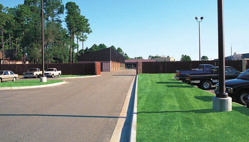
Air Mobility Command’s civil engineer squadrons provide
vital support to the Air Mobility Team. They construct,
operate, and maintain AMC’s facilities; provide emergency
services; and orchestrate our efforts to preserve and enhance
the environment.
As these civil engineering troops are leading the charge to
upgrade facilities in our command, AMC needs to give them
an environment in which they can be fully productive and
proud to serve. This guide sets new standards—they will be
the keys to success in planning, programming, design, and
construction of excellent facilities.

 “The Air Mobility Team...Responsive Global Reach for America...Every Day!”

                                                                              i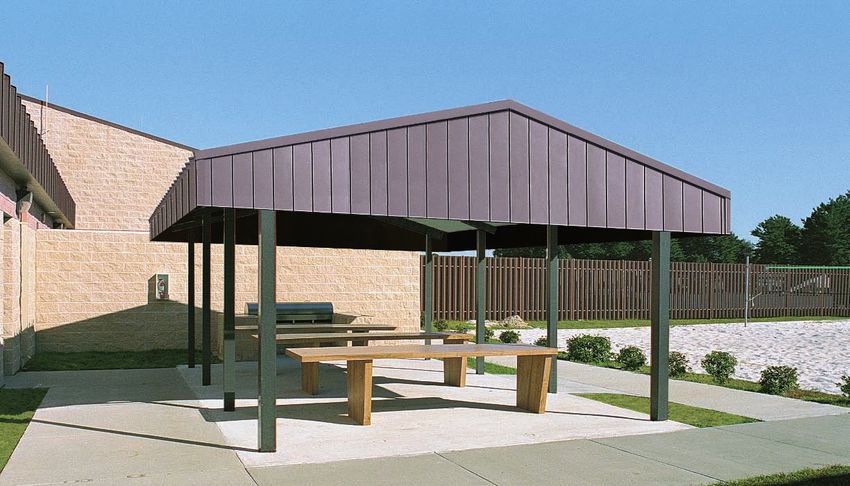
Table of Contents
Chapter 1
Introduction                                                                                                                                1

     A. Purpose . . . . . . . . . . . . . . . . . . . . . . . . . . . . . . . . . . . . . . . . . . . . . . . . . . . . . . . . . . . . . . 1
     B. Project Development . . . . . . . . . . . . . . . . . . . . . . . . . . . . . . . . . . . . . . . . . . . . . . . . . . . . 2
        1. Planning
        2. Programming
        3. Design
        4. Construction

Chapter 2
Site Considerations                                                                                                                         3

     A. General . . . . . . . . . . . . . . . . . . . . . . . . . . . . . . . . . . . . . . . . . . . . . . . . . . . . . . . . . . . . . . 3
     B. Functional Area Relationships . . . . . . . . . . . . . . . . . . . . . . . . . . . . . . . . . . . . . . . . . . . . . 3
     C. Exterior Elements . . . . . . . . . . . . . . . . . . . . . . . . . . . . . . . . . . . . . . . . . . . . . . . . . . . . . . . 4
        1. General
        2. Entries
        3. Exterior Signs
        4. Parking Areas
        5. Exterior Storage Areas
        6. Screen Walls
        7. Landscaping
        8. Exterior Break Area

ii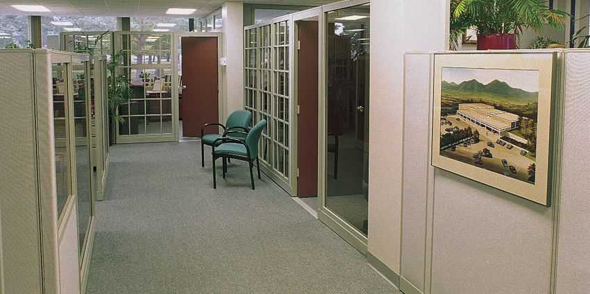
TABLE OF CONTENTS

Chapter 3
Functional Areas                                                                                                                           7

 A. General . . . . . . . . . . . . . . . . . . . . . . . . . . . . . . . . . . . . . . . . . . . . . . . . . . . . . . . . . . . . . . 7
 B. Administration Area . . . . . . . . . . . . . . . . . . . . . . . . . . . . . . . . . . . . . . . . . . . . . . . . . . . . 7
    1. Command Section
    2. Engineer Flight
    3. Environmental Flight
    4. Operations Center
    5. Resources Flight
 C. Shop/Warehouse Areas . . . . . . . . . . . . . . . . . . . . . . . . . . . . . . . . . . . . . . . . . . . . . . . . . . 15
    1. Operations Flight
    2. Readiness Flight
 D. Remote Facilities . . . . . . . . . . . . . . . . . . . . . . . . . . . . . . . . . . . . . . . . . . . . . . . . . . . . . . 23
    1. Explosive Ordnance Disposal Flight
    2. Entomology Facility

Chapter 4
Interior Standards                                                                                                                      29

 A.   General . . . . . . . . . . . . . . . . . . . . . . . . . . . . . . . . . . . . . . . . . . . . . . . . . . . . . . . . . . . . . 29
 B.   Color Concepts. . . . . . . . . . . . . . . . . . . . . . . . . . . . . . . . . . . . . . . . . . . . . . . . . . . . . . . . 29
 C.   Floor Coverings . . . . . . . . . . . . . . . . . . . . . . . . . . . . . . . . . . . . . . . . . . . . . . . . . . . . . . . 29
 D.   Wallcoverings . . . . . . . . . . . . . . . . . . . . . . . . . . . . . . . . . . . . . . . . . . . . . . . . . . . . . . . . . 29
 E.   Ceilings . . . . . . . . . . . . . . . . . . . . . . . . . . . . . . . . . . . . . . . . . . . . . . . . . . . . . . . . . . . . . 29
 F.   Window Coverings . . . . . . . . . . . . . . . . . . . . . . . . . . . . . . . . . . . . . . . . . . . . . . . . . . . . . 29
 G.   Accessories. . . . . . . . . . . . . . . . . . . . . . . . . . . . . . . . . . . . . . . . . . . . . . . . . . . . . . . . . . . 29
 H.   Signs . . . . . . . . . . . . . . . . . . . . . . . . . . . . . . . . . . . . . . . . . . . . . . . . . . . . . . . . . . . . . . . 29
 I.   Systems Furniture . . . . . . . . . . . . . . . . . . . . . . . . . . . . . . . . . . . . . . . . . . . . . . . . . . . . . 30
 J.   Lighting . . . . . . . . . . . . . . . . . . . . . . . . . . . . . . . . . . . . . . . . . . . . . . . . . . . . . . . . . . . . . 30
 K.   Communications. . . . . . . . . . . . . . . . . . . . . . . . . . . . . . . . . . . . . . . . . . . . . . . . . . . . . . . 30

References                                                                                                                              40

                                                                                                                                               iii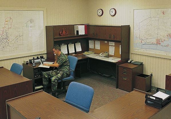
TABLE OF CONTENTS

List of Figures

     Number       Description                                               Page
     Figure 1-A   Functional Area Relationships                                1
     Figure 2-A   Concept Site Plan for the CE Complex                         3
     Figure 2-B   Concept Plan for Optional Two-Story Administration Area      4
     Figure 3-A   Location of the Administration Area in the CE Complex        7
     Figure 3-B   Command Section Concept Floor Plan                           8
     Figure 3-C   Engineer Flight Concept Floor Plan                          11
     Figure 3-D   Environmental Flight Concept Floor Plan                     12
     Figure 3-E   Operations Center Concept Floor Plan                        13
     Figure 3-F   Resources Flight Concept Floor Plan                         14
     Figure 3-G   Location of the Shop/Warehouse Areas in the CE Complex      15
     Figure 3-H   Heavy Repair Element Concept Floor Plan                     16
     Figure 3-I   Zonal Maintenance Shop Concept Floor Plan                   18
     Figure 3-J   Typical Zonal Maintenance Shop
                    Concept Floor Plan (Outside the CE Complex)               18
     Figure 3-K   Infrastructure Element Concept Floor Plan                   19
     Figure 3-L   Logistics Management Element Concept Floor Plan             20
     Figure 3-M   Main CE Building Concept Floor Plan                         21
     Figure 3-N   Readiness Flight Concept Floor Plan                         22
     Figure 3-O   EOD Flight Concept Floor Plan                               24
     Figure 3-P   Entomology Facility Concept Floor Plan                      25

List of Tables

     Number       Description                                                Page
     Table 3-A    Functional Space Requirements for the Main CE Building    26-27
     Table 3-B    Functional Space Requirements for the Readiness Flight,
                    EOD Flight, and Entomology Facility                        28
     Table 4-A    Finish Schedule                                           31-33
     Table 4-B    Furnishings Schedule                                      34-36
     Table 4-C    Equipment Schedule                                        37-39

iv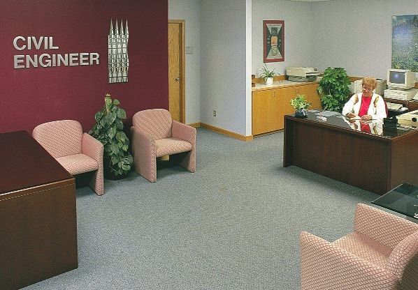
Chapter 1

Introduction
A. Purpose                                                           the AMC Commander’s Guide to Family Housing Excel-
                                                                     lence, the Air Force Housing Support Facilities Guide, the
This guide provides the basic criteria to organize, evaluate,        AMC and Air Combat Command Fire Station Facilities
plan, program, and design Air Mobility Command (AMC)                 Design Guide, and the Commander’s Guide to Self-Help
civil engineer (CE) facilities. The information presented            Success.
is intended to make commanders and their staffs aware of
important design considerations and to aid them in pro-              A typical CE squadron operates from multiple facilities. The
ject development. These facilities should provide an                 CE complex contains the main CE building, the readiness
atmosphere in which customers feel comfortable while                 facility, covered storage facilities, the vehicle wash rack, and
receiving quality assistance. This guide is for use by com-          the gas mask confidence facility. Some members of the
manders, Headquarters AMC staff, design architects and               squadron work outside the complex in “remote” facilities,
engineers, and others involved in CE facilities design and           which include the entomology and explosive ordnance dis-
construction. Use this guide to supplement other Air                 posal facilities.
Force (AF) and Department of Defense (DoD) policies                  This guide organizes the various functions of the CE
and instructions.                                                    squadron into administration and shop/warehouse areas,
Chapters 2 and 3 address most of the flights of a CE                 then discusses the squadron’s remote facilities (Figure 1-A).
squadron. Family housing, fire station, and self-help store          Chapter 2 addresses the functional area relationships
facility design guidelines have already been published in            between these areas in more detail.

                                                                                      WARE-
                                                                                      HOUSE
                                                    EXTERIOR STORAGE                                           EXTERIOR STORAGE
                                                                                      AREAS
    REMOTE FACILITIES

                                                                                    SHOP AREAS
      ENTOMOLOGY
      FACILITY

                              READI-
                                             VISITOR AND STAFF ENTRANCE                                     STAFF ENTRANCE
                              NESS
        EXPLOSIVE             FACILITY
        ORDNANCE              (SHOP/                                             ADMINISTRATION
        DISPOSAL              WARE-                                              AREA
                                                         VISITOR                                                  STAFF
        (EOD)                 HOUSE                      AND                                                      PARKING
                              AREAS)                     STAFF
                                                         PARKING

                                                                                    MAIN ENTRANCE

Figure 1-A: Functional Area Relationships.
                                                                                                                                   1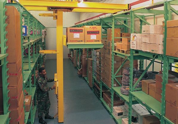
INTRODUCTION

B. Project Development                                          Life safety code requirements take precedence over other
                                                                facility improvement requirements. All areas should be
1. Planning                                                     barrier free and accessible to the disabled in accordance
Good planning establishes the objectives for an effective       with the Americans with Disabilities Act (ADA) and
program and provides the means to help meet them. It            Uniform Federal Accessibility Standards (UFAS).
should also lead to a timetable for project completion.
                                                                The designer should complete an overall comprehensive
Planning must be long-term. When planning a new
                                                                interior design (CID) standard for your facilities in con-
facility, complete the site selection prior to preparing a
                                                                junction with any major design project. The CID standard
DD Form 1391, Military Construction Project Data.
                                                                addresses interior finishes, artwork, signs, and furnishings.
2. Programming                                                  It ensures even small upgrade projects meet the design
Programming includes determining user requirements,             objectives for all CE facilities. Refer to the AMC Interior
developing solutions, identifying funding sources, and          Design Guide for an expanded discussion of interior design.
forwarding programming documents to the appropriate             Integration of engineering, architectural, and interior
review and approval authorities. Each project should be         design considerations during project development creates
consistent with the base comprehensive plan for new and         a well coordinated interior design. Analyze an existing
existing facilities. Work is classified as maintenance,         facility’s structural, electrical, communications, and
repair, or minor construction. Information required dur-        mechanical systems before planning interior design
ing preparation of the DD Form 1391, which initiates            upgrades. The designer should include infrastructure
project development, is found throughout this guide.            improvements concurrently with interior finish work
Included are considerations of space criteria, overall facil-   when appropriate.
ity size, and special factors for use in estimating costs.
                                                                4. Construction
3. Design                                                       Quality reviews of the contractors’ submittals by project
Design includes concept development, design reviews, and        engineers and frequent on-site inspections by civil engi-
final design drawings and specifications. It is important for   neering construction management personnel and the user
all participants to actively communicate throughout the         will help to ensure design goals are met.                 ■
design process to bring about a successful project.

2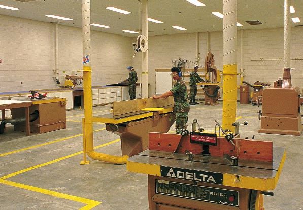
Chapter 2

Site Considerations
A. General                                                                  B. Functional Area
This chapter includes functional area relationships within                     Relationships
the CE complex, as well as exterior elements. Use the                       The CE squadron is a team of engineers, architects,
guidance that suits the needs of your squadron, increases                   craftsmen, logisticians, and administrators. The squad-
your operations’ efficiency, and enhances the visual quality                ron operates most efficiently when the following are near
of your squadron’s facilities.                                              each other:
                                                                            ◆      Command Section
                                                                            ◆      Engineer Flight
                                                                            ◆      Environmental Flight
                                                                            ◆      Resources Flight
                                                                            ◆      Operations Center

            COVERED STORAGE FOR                                          VEHICLE                                      COVERED STORAGE FOR
            EQUIPMENT AND SUPPLIES                                       WASH                                         EQUIPMENT AND SUPPLIES
                                                                         RACK

              EXTERIOR STORAGE                                                       STOCK STORAGE AREA
              AREA FOR BUILDING                                                      RECEIVING
              MATERIALS
                                                                                                                                  SECURED GATE

             GAS MASK
                                                                                                       MAIN CE
             CONFIDENCE FACILITY
                                                                                                       BUILDING
           READINESS          SECURED GATE
           VEHICLE
           PARKING
                               READINESS FACILITY                                                                                    SECURED
                                          SECURED GATE                                                                               GATE

         OUTSIDE
         DEMON-
                                                     SECONDARY ENTRIES                                        SECONDARY ENTRIES
         STRATION
         AREA                                     STAFF PARKING                                                     EXTERIOR BREAK AREA
                                VISITOR
                                PARKING
         STAFF
                                                 VISITOR PARKING                                                    STAFF PARKING
         PARKING

                                                                    VISITOR DROP-OFF          MAIN ENTRANCE

Figure 2-A: Concept Site Plan for the CE Complex.

                                                                                                                                                 3
SITE CONSIDERATIONS

Locate these flights in the administration area of the           Utility plants, entomology facilities, snow removal
main CE building. This administration area should be             equipment storage facilities, and outdoor readiness training
near the main entrance to the CE complex so visitors can         areas are other examples of squadron facilities which are
easily identify it.                                              separate from the complex. This guide does not address
                                                                 utility plants or snow removal equipment storage facilities
A one-story facility is the AMC standard, though site
                                                                 in detail.
concerns such as availability of land may dictate a two-
story administration area design. In that case, locate the
Command Section with the Operations Center and
Resources Flight on the lower level, and the Engineer and
Environmental Flights on the upper level (see Figure 2-B).

                                             COMMAND SECTION,
                                             RESOURCES FLIGHT,
                  ENGINEER AND               AND OPERATIONS
                  ENVIRONMENTAL              CENTER
                  FLIGHTS

               ADMINISTRATION AREA                               Entomology facilities should be separate from the main CE building.

Figure 2-B: Concept Plan for Optional Two-Story Administration
            Area.
                                                                 C. Exterior Elements
Provide a “zonal maintenance” shop in each major
                                                                 1. General
geographic area or “zone” of the base. The squadron              Exterior elements provide the first impression visitors
commander determines the number of zones depending               have of the squadron’s facilities and quality of service.
on the mission and size of the base. For small bases with        This section addresses entries, exterior signs, parking
only one or two zones, it is feasible to locate all zonal        areas, exterior storage areas, screen walls, landscaping,
maintenance shops in the CE complex as long as each              and an exterior break area. The Architectural Compat-
zone’s shops are separate.                                       ibility Plan for each base will help in the design of
                                                                 these elements.
Locate the readiness facility in the CE complex
because squadron personnel frequently need to use the
readiness classrooms for training. Because the Explosive
Ordnance Disposal (EOD) Flight stores and uses small
explosives, locate it in a facility which meets applicable
safety standards.

4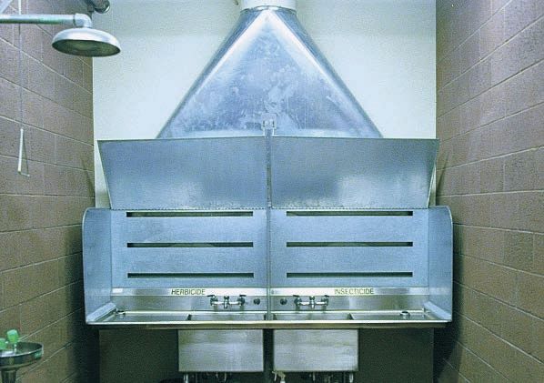
SITE CONSIDERATIONS

2. Entries                                                                  4. Parking Areas
The entry to the CE complex and its administration area                     Include designated spaces for visitors and squadron
should be easily identifiable to first time visitors. Provide               staff. Locate handicapped parking near building entries.
a visitor drop-off area at the main entrance to the adminis-                Parking requirements will depend on the size of the
tration area. Consider secondary entries near parking                       squadron. Parking for all privately owned vehicles should
areas for squadron personnel.                                               be separate from equipment storage areas and other gov-
                                                                            ernment vehicle parking areas.
3. Exterior Signs
Exterior signs include facility, directional, and parking                   ◆   Parking for government vehicles should be within a
signs. Follow the AMC sign standards. Locate facility                           secure, screened compound, adjacent to the shops and
signs at the primary entrance to the CE complex and                             logistics management areas.
remote facilities. Directional signs should guide vehicle                   ◆   Provide additional parking at the readiness facility
and pedestrian traffic to each facility. Use parking signs                      for base personnel who attend training classes.
to designate visitor, staff, and handicapped parking areas.                 ◆   Secure EOD Flight parking areas with a fence and
                                                                                double gate. Include security lighting in these areas
                                                                                (see Figure 3-O, page 24).

Use screen walls around unattractive storage areas, and provide ample off-street parking for visitors.

                                                                                                                                        5
SITE CONSIDERATIONS
5. Exterior Storage Areas 6. Screen Walls
The CE complex and EOD facility require exterior Screen walls can hide exterior shop and storage areas. The
storage areas with power outlets and lighting. Locate a design of screen walls is part of each base’s Architectural
covered storage area in the complex for building materials Compatibility Plan.
and miscellaneous small equipment.
7. Landscaping
Landscaping elements help create a quality appearance
around all CE facilities. These elements screen parking
areas and define building entries. Landscaping elements
include earth berms, shrubs, trees, and flowers. Refer to
the AMC Landscape Design Guide for specific information.
8. Exterior Break Area
Provide a covered patio to serve as a break area and a per-
sonnel gathering place for squadron activities. Locate this
area away from the complex entrance, and provide privacy
through the use of screen walls and landscaping. ■
Exterior covered storage facilities should include overhead doors to
secure equipment and supplies, and provide ease of access.
Provide an exterior break area for squadron activities.
6Chapter 3
Functional Areas
A. General
This chapter addresses the functional areas of each
flight within the administration area, shop/warehouse
areas, and remote facilities. The discussion includes the
support each flight provides to the squadron’s mission,
interaction between the squadron’s flights, and special
requirements for the flights to function efficiently.
B. Administration Area
The Command Section, Engineer Flight, Environmental
Flight, Operations Center, and Resources Flight require an
office environment. A large portion of the office space
should be open areas with systems furniture. Command
Section, flight, and element supervisors require private
offices near their respective open office areas so they can
manage their personnel and provide private counseling.
Administration support areas are for common use and
include a main conference room, a copy machine room, Figure 3-A: Location of the Administration Area in the
a central break area, and rest rooms. CE Complex.
◆ Corridors should provide clear paths from administra-
tion area lobbies to the various flights.
◆ Conference and administration support areas are infre-
quent-use areas not requiring natural light. Locate
these areas at the interior portions of open office areas.
◆ Centrally locate a main conference room for 30-35
people between the administration and shop areas of
the main CE building. Include space for communica-
tions and audio-visual equipment.
7FUNCTIONAL AREAS
1. Command Section
The Command Section is responsible for the daily super-
vision of all squadron activities. It includes the squadron
commander, deputy base civil engineer, secretary/adminis-
tration, squadron section commander (where authorized),
first sergeant, orderly room, and conference room.
The Command Section interacts with all squadron flights
on a regular basis. The Command Section should be easy
to locate, have adequate directional and identification
signs, and be accessible to visitors.
a. The squadron commander should have an executive
office. Provide a waiting area for visitors to the Command Section.
b. The deputy base civil engineer should have an executive
office adjacent to the squadron commander’s office.
DEPUTY WAITING
BASE CIVIL AREA SQUADRON SECTION
ENGINEER’S COMMANDER’S OFFICE
OFFICE
SECRETARY/
ADMINISTRATION
CONFERENCE COUNTER
ROOM
ORDERLY ROOM
SQUADRON
COMMANDER’S
OFFICE
FIRST SERGEANT’S OFFICE
PRIVATE ENTRANCE
Figure 3-B: Command Section Concept Floor Plan.
8FUNCTIONAL AREAS
c. Provide a small conference room for 12 -15 people for
small group meetings chaired by the squadron commander
or the deputy base civil engineer.
d. Squadron members visit the orderly room for weight
checks, physician and dental appointment coordination,
training appointments, status changes, and paperwork
distribution. Locate this room centrally within the
administration area so all members have easy access.
e. The squadron section commander supervises the orderly
room staff and acts as the squadron commander’s executive
officer. Locate a private office for the squadron section
commander adjacent to the orderly room. The orderly room should have a reception counter.
f. Include a private office for the first sergeant adjacent to
the orderly room.
The main conference room should accommodate 30-35 people.
Provide a central break area which includes counters, sinks, and appli-
ances for food preparation.
9FUNCTIONAL AREAS
2. Engineer Flight
This flight is responsible for programming, design, and
construction management of large scale facility projects.
Locate this flight within the administration area near the
Environmental Flight and Operations Center.
◆ Include a private office for the flight chief.
◆ Locate a small conference room for 12-15 people in
this flight for project review meetings.
◆ Provide an uninterruptible power source for drawing
reproduction equipment and at least one computer
aided drafting and design (CADD) workstation for
base exercises and other contingency operations. Separate the sections of the Engineer Flight with well-defined
a. Programming personnel receive work requests and create corridors.
project justification documents. They work closely with
customers, design engineers, Simplified Acquisition for
Base Engineer Requirements (SABER) project managers,
and financial managers.
b. Design engineers and engineer assistants design in-
house and contract work. This work includes periodic
design reviews with multiple base agencies (safety office,
bio-environmental engineers, communications squadron,
security police squadron, users, and base operations) and
outside agencies such as design agents, major command
representatives, and architect – engineer firms.
c. Construction managers oversee the construction phase
of projects. Though they are often monitoring projects on-
site, they require workspaces to prepare inspection reports
The Engineer Flight should have a conference room for project review
and review construction drawings and specifications. meetings.
d. The Engineer Flight also manages the SABER con-
tract with a civilian contractor. SABER enables the
squadron to quickly complete construction projects
that do not require complicated design efforts.
10FUNCTIONAL AREAS
COPY
MACHINE
ROOM
PLOTTER AND
BLUE PRINT
MACHINES EMERGENCY
EXIT
CONFERENCE
ROOM
PERSONNEL
MAIN CORRIDOR WORKSPACE
(TYPICAL)
EMERGENCY
SECRETARY/ EXIT
ADMINISTRATION
FLIGHT
CHIEF’S
OFFICE
Figure 3-C: Engineer Flight Concept Floor Plan.
11FUNCTIONAL AREAS
3. Environmental Flight a. Environmental restoration personnel manage all envi-
This flight manages the environmental restoration and ronmental remediation efforts on the base, including the
environmental compliance programs for the wing. The design and construction phases. They work closely with
flight frequently interacts with numerous outside agencies, the Engineer Flight to manage these projects.
public and private. Flight personnel work efficiently in an b. Environmental compliance personnel ensure that
open office area. There should be a distinct separation the wing complies with applicable laws and regulatory
between the various functions within the flight. Provide a requirements, and educates and trains the base populace
private office for the flight chief. File storage areas and an on environmental issues and programs. They manage the
accessible conference room are also required. wing’s pollution prevention program; environmental com-
The Environmental Flight frequently interacts with the pliance, assessment, and management program (ECAMP);
Command Section, as well as the Engineer, Operations, environmental funding programs; and natural and cultural
and Resources Flights. resources management programs.
MAIN CORRIDOR
FILE STORAGE AREA
EMERGENCY EXIT
SECRETARY/
ADMINISTRATION
FLIGHT
CHIEF’S
OFFICE
Figure 3-D: Environmental Flight Concept Floor Plan.
12FUNCTIONAL AREAS
4. Operations Center This flight should also house the damage control center,
Locate flight and element supervisors in the administration which should include sufficient space for 10-12 personnel,
area. a radio base station, and wall space for charts, maps, and
tracking boards for contingency operations. Include com-
a. The following personnel require private offices: puter and communications equipment with an
◆ Flight chief uninterruptible power source.
◆ Deputy flight chief b. Maintenance Engineering incorporates an engineering
◆ Heavy Repair superintendent
capability in the Operations Flight to provide an effective
liaison between the Engineer and Operations Flights.
◆ Facility Maintenance superintendent (supervises all
Locate the element near the Engineer Flight since they
zonal maintenance shops) frequently interact on project work.
◆ Infrastructure superintendent
Include a fire-resistant vault/storage room to store facility
The flight chief and secretary interact daily with most of drawings and an adjacent fume-vented drawing reproduc-
the other flights in the squadron. Other members of the tion room.
Operations Center staff primarily interact with the shops,
the orderly room, and the Resources Flight.
HEAVY REPAIR INFRASTRUCTURE
SUPERINTENDENT’S SUPERINTENDENT’S
OFFICE OFFICE
FACILITY MAINTENANCE DRAWING
SUPERINTENDENT’S REPRODUCTION
OFFICE DAMAGE
CONTROL
VAULT/
CENTER AND
STORAGE
RADIO BASE
ROOM
FLIGHT STATION
CHIEF’S
OFFICE
MAIN CORRIDOR
MAINTENANCE ENGINEERING
SECRETARY/
WORKSPACES
ADMINISTRATION
DEPUTY
STAFF FLIGHT
ENTRANCE CHIEF’S
OFFICE
Figure 3-E: Operations Center Concept Floor Plan.
13FUNCTIONAL AREAS
5. Resources Flight a. Real estate managers maintain records on all base
This flight manages real estate files, squadron information facilities. They require workspaces at the interior of
systems, and financial resources. They require ample stor- the flight area.
age for files and records. Locate an environmentally clean b. Information systems administrators should have work-
room for the main-frame computer and server in this area. spaces adjacent to the main-frame computer room.
Include dedicated utilities for the computer room.
c. Financial managers process funding requests daily
This flight interacts with all other flights in the squadron for CE personnel. Locate this area at the front of the
on a daily basis. Locate this flight in a central location Resources Flight for ease of access and to minimize inter-
within the administration area to provide the easiest access ruptions to other flight activities. Provide a working area
for all squadron personnel. for analysis work.
MAIN CORRIDOR
MAIN-FRAME
COMPUTER ROOM
WORKING AREA
SECRETARY/ FINANCIAL
ADMINISTRATION MANAGEMENT’S
WORKSPACES
REAL ESTATE
MANAGEMENT’S INFORMATION SYSTEMS
WORKSPACES MANAGEMENT’S
FLIGHT WORKSPACES
CHIEF’S
OFFICE
FILE STORAGE
Figure 3-F: Resources Flight Concept Floor Plan.
14FUNCTIONAL AREAS
C. Shop/Warehouse Areas
These areas support the Operations Flight and its many
elements. Most personnel begin work days at their
respective shops, storing personal items in the locker
areas, receiving work assignments, and leaving to service
various base facilities. Sometimes they bring service
items, such as electrical or mechanical components,
back to their shops for repair.
The logistics management area provides storage space for
building supplies and equipment. Shop personnel visit this Figure 3-G: Location of the Shop/Warehouse Areas in the
area to obtain bench stock for their shops and parts/sup- CE complex.
plies for work orders.
◆ Provide a covered work area outside the shops where
craftsmen handle oversized parts. Incorporate overhead
cranes into the roof structures of shops that support
heavy equipment repair.
◆ Include an indoor corridor between the shops
for weather protected access to the warehouse and
administration area.
◆ Integrate a central dust collection system for shops
with woodworking tools. Include air exhaust systems
for the paint area and vehicle maintenance bays, which
produce hazardous fumes.
◆ Include a private office in each shop area for the shop
supervisor, a technical library area for repair manuals, A covered work area outside the shops provides additional space for
adequate work space for tools and equipment, and a craftsmen to service equipment.
break area with lockers for the shop personnel. Locate
shower facilities near the shops.
◆ Provide a mechanical room and rest rooms (with show-
ers for shop personnel) in the support areas.
15FUNCTIONAL AREAS
1. Operations Flight
This flight’s responsibilities include managing and conduct-
ing all facility and infrastructure maintenance, small repair
and construction projects, and most service contracts.
a. The Heavy Repair element includes the vertical and
horizontal shops. These shops perform the more compli-
cated in-house facility repair and construction projects.
Include an open office area for work planners. The verti-
cal shop should have structural, sheet metal, plumbing,
electrical, and paint areas.
The horizontal shop maintains base pavements, is
responsible for landscaping, and performs entomology Some vehicles require servicing within shop facilities.
services. This shop also manages snow removal opera-
tions. The entomology facility is a remote facility
outside the complex.
Include storage and maintenance space for government
vehicles, equipment, and indoor storage for perishable
supplies.
COVERED WORK AREA
VERTICAL SHOP
LOCKERS/ VERTICAL SHOP (SHEET METAL) VERTICAL
BREAK AREA (ELECTRICAL) SHOP
TECH. VERTICAL TECH. TECH. (PAINT)
LIBRARY SHOP LIBRARY LIBRARY
(PLUMB- OFFICE
HORIZONTAL SHOP
ING)
OFFICE OFFICE OFFICE
OFFICE TECH.
MAIN CORRIDOR LIBRARY
TECH. OFFICE
LIBRARY
VERTICAL
SHOP
LOCKERS/BREAK AREA VERTICAL SHOP LOCKERS/
(WORK
(STRUCTURAL) BREAK
PLAN-
AREA
NERS)
Figure 3-H: Heavy Repair Element Concept Floor Plan.
16FUNCTIONAL AREAS
b. Facility maintenance includes the zonal maintenance
shops. Shop personnel perform routine facility mainte-
nance and repair. The shops have the following areas:
◆ Shop supervisor’s office
◆ Customer service area
◆ Work controller’s office
◆ Work assignment and break area
◆ Tool and equipment storage
◆ Areas for structural and locksmith, plumbing, interior
electric, and sheet metal
◆ Interior and exterior storage
The shop supervisor’s office should have a window to the shop for
Provide a customer service area which has direct access to supervision.
the shop supervisor’s office and the shop.
Zonal maintenance shops outside the complex require
additional shop space and support areas (see Figures 3-I
and 3-J, page 18).
Shops should have adequate clearances around equipment.
Provide a professional, interactive environment in the customer ser-
vice area.
17FUNCTIONAL AREAS
TO0L ROOM
SHOP
SUPERVI-
SHOP AREA SOR CUSTOMER SERVICE
AREA/WORK
CONTROLLER’S
OFFICE
WORK ASSIGNMENT
AND BREAK AREA
Figure 3-I: Zonal Maintenance Shop Concept Floor Plan.
SHOP
SUPERVISOR
LOCKERS
WORK ASSIGNMENT AND SHOP AREA
BREAK AREA CUSTOMER
SERVICE
CABINETS/COUNTER
AREA
PERSONNEL MAIN
ENTRANCE ENTRANCE
MEN WOMEN
MECHAN-
ICAL TOOL
ROOM
Figure 3-J: Typical Zonal Maintenance Shop Concept Floor Plan (Outside the CE Complex).
18FUNCTIONAL AREAS
c. The Infrastructure Element monitors and maintains the These shops require indoor and outdoor storage areas for
base’s utility distribution systems from the following shops, specialized vehicles, large equipment, and materials (trans-
some of which may not be in the CE complex: formers, piping, etc.). Consider environmental hazard
prevention, such as oil/water separators and fume ventila-
◆ Electric distribution
tors, at all working and storage areas. Include additional
◆ Power production indoor work space for bases which experience frequent
◆ Energy management and control systems (EMCS), if periods of inclement weather.
applicable
EMCS monitors energy consumption in critical base facili-
◆ Utility plants (heat, water and waste water treatment, ties. After-hours monitoring is done from the squadron’s
and power), if applicable 24-hour emergency service center. Provide an environ-
◆ Liquid fuels mentally clean room with raised flooring and dedicated
power for the EMCS computer equipment.
COVERED WORK AREA
LOCKERS/ LOCKERS/
LIQUID BREAK AREA BREAK AREA
FUELS POWER PRODUCTION ELECTRIC
SHOP SHOP DISTRIBUTION EMCS SHOP
TECH. TECH.
LIBRARY SHOP LIBRARY
OFFICE OFFICE OFFICE OFFICE
Figure 3-K: Infrastructure Element Concept Floor Plan.
19FUNCTIONAL AREAS
d. Logistics Management maintains and controls the ◆ Stock storage area
material resources and vehicles used by the squadron. ◆ Government Operated Civil Engineer Supply Store
Centrally locate this element within the shop/warehouse (GOCESS)/Contractor Operated Civil Engineer
areas for ease of access to materiel. Supply Store (COCESS)
Functional areas include: Provide modular and high density shelves to maximize
storage capacity. Include a lift to retrieve supplies from
◆ Supervisor’s office
high shelves.
◆ Vehicle control officer’s office
◆ Material control section
Provide modular shelves for supplies in the stock storage area. Use high density shelves to store small parts in efficient compartments.
SUPERVISOR’S STOCK STORAGE
OFFICE AREA/GOCESS/COCESS
VEHICLE
CONTROL
OFFICER’S
OFFICE
MATERIAL
CONTROL
SECTION
COUNTER
Figure 3-L: Logistics Management Element Concept Floor Plan.
20FUNCTIONAL AREAS
MAIN CE BUILDING
LOGISTICS MANAGEMENT
MECHANICAL ROOM
INFRASTRUCTURE HEAVY REPAIR
REST ROOMS/SHOWERS
FACILITY MAINTENANCE
ADMINISTRATION
RESOURCES FLIGHT SUPPORT AREAS
OPERATIONS CENTER
ENGINEER FLIGHT
COMMAND SECTION
ENVIRONMENTAL FLIGHT
MAIN ENTRANCE
Figure 3-M: Main CE Building Concept Floor Plan.
21FUNCTIONAL AREAS
2. Readiness Flight GAS MASK
CONFIDENCE FACILITY
The Readiness Flight ensures the squadron is prepared
to meet any peacetime or wartime contingency. This
includes the following training:
◆ Disaster preparedness
◆ Prime Base Engineer Emergency Force (BEEF)
◆ Air base operability
◆ Hazardous material
Readiness personnel interact daily with squadron and base WAREHOUSE STORAGE
AND
personnel. They operate and maintain the squadron dam- MOBILITY PROCESSING
age control center in the main CE building and a nuclear,
biological, and chemical (NBC) control center in the
readiness facility. They also operate the gas mask confi-
dence facility.
VEHICLE
STORAGE
The readiness facility should have adequate space for TRAINING
administration offices, training classrooms, and storage. SECURE
CLASSROOM
The training NCO’s office may also be in this facility. STORAGE
AREA
This manager is responsible for all skill level upgrade
and professional development training.
Provide offices for the following:
LOGISTICS PROJECTION
OFFICE ROOM VISITOR
◆ Flight Chief PARKING
OUTSIDE INSIDE
◆ Training NCO DEMON- DEMON- TRAINING
STRATION STRATION CLASSROOM
◆ Readiness operations AREA ROOM
◆ Readiness training
◆ Logistics MEN
Provide storage space for the following: HAZMAT
CERTIFICATION
◆ Chemical warfare training equipment TESTING
ROOM
WOMEN
◆ Mobile command post
FENCE TRAINING
◆ Disaster preparedness equipment MECH. NBC NCO’S
CONTROL OFFICE
CENTER
◆ Prime BEEF equipment sets, tool boxes, and mobility STUDENT
bags BREAK ROOM
The training classrooms should have space for seating and STAFF MAIN
several computer work stations for skill level upgrade training. PARKING ENTRANCE
Equip rest rooms with showers and provide access from the SECRETARY
ADMIN.
outside demonstration area and gas mask confidence facility. READINESS
OPERATIONS
READINESS
FLIGHT TRAINING
WORKSPACES WORKSPACES
CHIEF’S
OFFICE
Figure 3-N: Readiness Flight Concept Floor Plan.
22FUNCTIONAL AREAS
D. Remote Facilities Locate this flight away from the CE complex, but near the
outdoor training area. The EOD facility should include
1. Explosive Ordnance Disposal Flight the following areas:
This flight is responsible for protecting people
◆ Flight chief’s office
and resources from the effects of weapons, weapon
components, and other hazardous components and ◆ EOD staff’s workspaces
devices. This includes storing hazardous materials. ◆ Reception/dispatch desk with radio base station
The Explosive Ordnance Disposal (EOD) Flight primarily ◆ Training room
interacts with others within the squadron for ordnance ◆ Physical fitness room
recognition training. This training is most effective on ◆ Maintenance and secure storage area
an outdoor training site. They also provide classroom and
◆ Vehicle storage bays
practical training to numerous federal and state agencies in
bomb search and neutralization procedures. Some base ◆ Primary weapons vault
missions do not require an EOD flight. Other bases may The open office area includes technical orders, operations,
be augmented by Air Force Reserve or Air National Guard supply, and training offices. Training includes hands-on
EOD units. In these cases, every effort should be made to access to models of explosive ordnance. Store these mod-
collocate these units with the active duty forces. els in display cabinets.
◆ Equip rest rooms with showers.
◆ Isolate the outdoor training area from populated areas
and weapons storage areas of the base.
Provide an outdoor area for on-site ordnance recognition training.
23FUNCTIONAL AREAS
FENCE
EXTERIOR SECURE
STORAGE SPACE AND
VEHICLE
PARKING
STORAGE
BAYS
MAINTENANCE
AND SECURE
STORAGE AREA
LAUNDRY
MAINTENANCE
AND SECURE MECHANICAL
STORAGE AREA
PHYSICAL
PRIMARY FITNESS
WEAPONS ROOM
VAULT
TRAINING ROOM JANITOR’S
CLOSET
DISPLAY CASE
RECEPTION/
DISPATCH DESK
EOD STAFF’S
WORKSPACES
FLIGHT
CHIEF’S
FENCE OFFICE
DOUBLE
GATE
Figure 3-O: EOD Flight Concept Floor Plan.
24FUNCTIONAL AREAS
◆ Provide exterior covered storage areas.
◆ Include outdoor and indoor parking for special EOD
vehicles.
◆ Incorporate a weapons vault with an integral security
system that can contract base security in case of unau-
thorized intrusion.
◆ Provide a communications system for paging.
◆ Include an electric door lock at the main entrance to
control visitor access to the facility and its explosive
supplies.
◆ Provide a temperature and humidity controlled space
for vehicle and equipment maintenance areas. The training room should include a television, table space, and a
display area for explosive ordnance models.
2. Entomology Facility
Isolate this facility from congested areas of the base and
design it to protect human health as well as the air, water,
and soil.
Provide an eye wash station in the mixing room, showers
in the rest rooms, and laundry facilities. Include ample
storage for personal protective equipment, emergency
supplies, and spill clean-up equipment. Insecticide and
herbicide storage areas should have containment curbs
so chemicals don’t spill into other rooms. The facility
should include provisions to collect, store, and recycle
rinsewater. ■
The reception/dispatch desk is the central point of contact for visitors.
MECH. WASHDOWN
EQUIPMENT
AREA
REPAIR INSECTICIDE
STORAGE
STORAGE
MAIN
ENTRANCE
BREAK MIXING
ROOM ROOM
LAUNDRY
REST HERBICIDE
ROOM
OFFICE STORAGE
Figure 3-P Entomology Facility Concept Floor Plan. Entomology facilities require vented exhaust hoods in the mixing room.
25FUNCTIONAL AREAS Functional Space Requirements for the Main CE Building (Typical AF Objective CE Squadron of 350 People) Functions Square Footage Square Meters(1) Administration Area Command Section Squadron Commander’s Office 200 19 Deputy Base Civil Engineer’s Office 150 14 Squadron Section Commander’s Office 120 11 First Sergeant’s Office 120 11 Secretary/Administration(2) 240 22 Orderly Room(3) 360 33 Conference Room (12 - 15 people) 225 21 Engineer Flight Flight Chief’s Office 150 14 Secretary/Administration 120 11 Programmers’ Workspaces(4) 480 45 Design Engineers’/Engineer Assistants’ Workspaces(5) 1,800 167 Construction Management’s Workspaces(6) 1,560 145 SABER Workspaces(3) 360 33 Conference Room (12 - 15 people) 225 21 Environmental Flight Flight Chief’s Office 150 14 Secretary/Administration 120 11 Environmental Program Managers’ Workspaces(7) 960 89 Operations Center Flight Chief’s Office 150 14 Deputy Flight Chief’s Office 120 11 Secretary/Administration 120 11 Facility Maintenance Superintendent’s Office 120 11 Infrastructure Superintendent’s Office 120 11 Heavy Repair Superintendent’s Office 120 11 Maintenance Engineering’s Workspaces(7) 960 89 Vault/Storage Room 300 28 Damage Control Center 300 28 Resources Flight Flight Chief’s Office 150 14 Secretary/Administration 120 11 Real Estate Management’s Workspaces(2) 240 22 Information Systems Management’s Workspaces(2) 240 22 Financial Management’s Workspaces(2) 240 22 Table 3-A: Functional Space Requirements for the Main CE Building. 26
FUNCTIONAL AREAS

                                      Functional Space Requirements for
                                       the Main CE Building (Continued)
 Functions                                                                                              Square Footage                                  Square Meters(1)
 Resources Flight (Continued)
 Working Area                                                                                                                 120                                               11
 File Storage Room                                                                                                            100                                                9
 Computer Room                                                                                                                250                                               23
 Administration Support Areas
 Break Areas                                                                                                                  200                                               19
 Copy Machine Rooms                                                                                                           100                                                9
 Rest Rooms                                                                                                                   500                                               47
 Janitor’s Closet                                                                                                              50                                                5
 Main Conference Room (30-35 people)                                                                                          525                                               49
 Shop/Warehouse Areas
 Operations Flight
 Heavy Repair Shop
 Vertical Shop(8)                                                                                                          9,500                                              883
 Horizontal Shop(8)                                                                                                        4,000                                              372
 Facility Maintenance
 Facility Maintenance Shop(8)                                                                                              3,000                                              279
 Customer Service/Work Controller’s Office                                                                                   150                                               14
 Infrastructure Element
 Electric Distribution Shop(8)                                                                                             1,200                                              112
 EMCS Shop(8)                                                                                                                300                                               28
 Power Production Shop(8)                                                                                                  1,500                                              139
 Liquid Fuels Shop(8)                                                                                                        400                                               37
 Logistics Management
 Material Control Section                                                                                                 1,180                                              110
 Stock Storage Area/GOCESS/COCESS                                                                                        16,000                                            1,487
 Vehicle Control Officer’s Office                                                                                           120                                               11
 Support Areas
 Mechanical Rooms                                                                                                          2,500                                              232
 Rest Rooms (with showers)                                                                                                   750                                               70
 Subtotal                                                                                                            53,085                                              4,932
 Circulation and Walls (15%)                                                                                              7,963                                              740
 Gross Total                                                                                                         61,048                                             5,672
Table 3-A Continued: Functional Space Requirements for the Main CE Building.
 Legend for Table 3-A.                          (1) Square Meters = .0929 x Square Footage ( All measurements are rounded.)
 (2) Two people at 120 square feet each.        (3) Three people at 120 square feet each.    (4) Four people at 120 square feet each.       (5) Fifteen people at 120 square feet each.
 (6) Thirteen people at 120 square feet each.   (7) Eight people at 120 square feet each.    (8) These are average shop sizes. Each squadron should adjust these sizes based on local requirements.

                                                                                                                                                                                                 27
FUNCTIONAL AREAS
Functional Space Requirements for the
Readiness Flight, EOD Flight, and Entomology Facility
Functions Square Footage Square Meters(1)
Readiness Flight
Flight Chief’s Office 150 14
Secretary/Administration 120 11
Readiness Staff’s Workspaces(2) 1,200 111
Training NCO’s Office 120 11
Logistics Office 120 11
HAZMAT Certification Testing Room (12-15 people) 400 37
(3)
Training Classrooms 1,400 130
Projection Room 120 11
Inside Demonstration Room 500 47
Student Break Room 400 37
Secure Storage Area 500 47
NBC Control Center 300 28
Vehicle Storage 300 28
Warehouse Storage and Mobility Processing(4) 5,000 464
Rest Rooms 300 28
Mechanical Room 400 37
Subtotal 11,330 1,052
Circulation and Walls (15%) 1,700 158
Gross Total for Readiness Flight 13,030 1,210
EOD Flight
Flight Chief’s Office 150 14
EOD Staff’s Workspaces(2) 1,200 111
Training Room 450 42
Physical Fitness Room 250 23
Maintenance and Secure Storage Area 1,900 176
Vehicle Storage Bays 2,460 229
Primary Weapons Vault 150 14
Laundry 75 7
Rest Rooms 300 28
Janitor's Closet 25 2
Mechanical Room 300 28
Subtotal 7,260 674
Circulation and Walls (15%) 1,089 101
Gross Total for EOD Flight 8,349 775
Gross Total for Entomology Facility(5) 1,800 167
Table 3-B: Functional Space Requirements for the Readiness Flight, EOD Flight, and Entomology Facility.
Legend for Table 3-B. (1) Square Meters = .0929 x Square Footage ( All measurements are rounded.) (2) Ten people at 120 square feet each.
(3) Two classrooms at 700 square feet each. (4) Sizing may vary depending on local storage or mobility processing requirements.
(5) This is an average facility size. Each squadron should adjust the size based on local requirements.
28Chapter 4
Interior Standards
A. General D. Wallcoverings
CE squadron facilities reflect the AMC standard of Use vinyl and acoustic wallcovering in all administration
“understated excellence” and create an environment areas. Select painted finishes in shop/warehouse areas in
where people can provide quality services. Select interior the main CE building for ease of maintenance.
finishes for cost-effectiveness and life cycle maintenance,
as well as appearance. Interior finishes that are durable E. Ceilings
and easy to maintain are essential. Quality interiors pro-
vide an environment which improves job performance Use suspended acoustical ceiling tile with a revealed edge
and customer satisfaction. In this chapter, Tables 4-A finish in all administration areas. A standardized 2’ x 2’
through 4-C offer guidance for finishing, furnishing, and tile is recommended as the consistent module throughout
equipping each functional area. CE facilities. Shop areas should have an open painted
ceiling. A gypsum board ceiling with water-resistant paint
B. Color Concepts works well in rest rooms.
Designers should give special attention to color selection F. Window Coverings
and provide a timeless color scheme. Use accent colors
sparingly to complement a neutral color scheme. Vertical blinds and miniblinds filter daylight and allow
outdoor views. Use lined draperies to block daylight for
Select a neutral color for carpets, wallcoverings, and sys- visual presentations in conference and training rooms.
tems furniture wall panels. Incorporate accent colors in
upholstery, graphics, borders, accessories, and artwork for G. Accessories
design scheme consistency.
Framed artwork, wall murals, and plants complement
C. Floor Coverings interior finishes and the design scheme. Choose only
professionally framed pictures and paintings with color
Consider patterned carpet tile for high-use areas such as schemes and images that contribute to the facility’s decor.
hallways, waiting areas, and training rooms in administra- Live plants or professional quality silk plants are optional.
tion areas. Avoid stripes and linear designs that are hard to
line up with walls in corridors, vestibules, or irregularly H. Signs
shaped areas.
Develop an interior sign plan as part of the comprehensive
◆ Select neutral colored carpet for offices. interior design. Use professionally made signs appropriate-
◆ Use vinyl composition tile in the corridors and break ly sized for the viewing distance and compatible with the
rooms, where cleanup of food and dirt is a daily task. design scheme. The main CE building entrance should
◆ Provide ceramic tile in rest rooms. have signs that clearly direct visitors to specific flights.
◆ Select a sealed concrete finish in warehouse, shop, and
storage areas for durability.
29INTERIOR STANDARDS
I. Systems Furniture The designer should provide natural and accent lighting
in all administration areas. Include task lighting at office
This furniture includes interchangeable wall panels, desk desks. Use high-efficiency fluorescent lighting in the
components, and storage modules which combine to form shops in lieu of incandescent lighting.
office workspaces. These stations allow for a reconfigura-
tion of office areas when requirements change. K. Communications
Select systems furniture that easily integrates computer Provide telephone and computer wiring to support fire
hardware. Systems furniture panels should incorporate alarm systems and other equipment listed in the Equipment
integrated conduits for electrical and communications Schedules (Table 4-C). Equip facilities with the capability
service. Sound absorbent fabric panels will reduce back- for intercom, cable television, Defense Systems Network
ground noise and provide a quiet work area. (DSN), Defense Information Systems Network (DISN), fax
Finish work surfaces in plastic laminate or wood. Plastic lines, on- and off-base lines, and Local Area Network (LAN)
laminate with a wrapped edge is an easily maintainable connections. The Operations, Readiness, and EOD Flights
finish. may require dispatch, STU III secure, and other communica-
tions equipment. Locate large antennae away from the main
◆ Use systems furniture in all offices except the squadron entrances of buildings. The designer should contact the base
commander’s, deputy base civil engineer’s, and communications squadron for specific communications
squadron commander’s secretary’s offices. requirements before planning major building upgrades or
modifications. Incorporate these requirements in building
J. Lighting design and modification specifications. ■
Natural and artificial lighting are important factors in
creating a quality interior appearance. Lighting affects the
perception of space, as well as the color of interior finishes.
Design lighting to enhance the design scheme.
Incorporate glass panels into systems furniture wall panels so light can filter throughout open office areas.
30INTERIOR STANDARDS
FLOORS BASE WALLS CEILING
sed ard
d E um ile
e
ng
Til
nte yps g T
xpo Bo
eri
Ce stic W ering
Sea ic T ition
Ac ic T llcov
Pai d G eilin
Vin uter ete
or
Flo
ram pos
ov
mp ncr
C
ile
ile
ous ile
a
Ac Wallc
l
Wo ic T
Ce Com
Pai tica
Co d Co
ram
Vin et
ram
nte
od
ou
le
Vin t
yl
yl
yl
rp
n
Pai
Ce
Ca
Administration Area
Command Section
Squadron Commander’s Office ♦ ♦ ♦ ♦
Deputy Base Civil Engineer’s Office ♦ ♦ ♦ ♦
Squadron Section Commander’s Office ♦ ♦ ♦ ♦
First Sergeant’s Office ♦ ♦ ♦ ♦
Secretary/Administration ♦ ♦ ♦ ♦
Orderly Room ♦ ♦ ♦ ♦ ♦
Conference Room ♦ ♦ ♦ ♦
Engineer Flight
Flight Chief’s Office ♦ ♦ ♦ ♦
Secretary/Administration ♦ ♦ ♦ ♦
Programmers’ Workspaces ♦ ♦ ♦ ♦
Design Engineers’/Engineer Assistants’ Workspaces ♦ ♦ ♦ ♦
Construction Management’s Workspaces ♦ ♦ ♦ ♦
SABER Workspaces ♦ ♦ ♦ ♦
Conference Room ♦ ♦ ♦ ♦
Environmental Flight
Flight Chief’s Office ♦ ♦ ♦ ♦
Secretary/Administration ♦ ♦ ♦ ♦
Environmental Program Managers’ Workspaces ♦ ♦ ♦ ♦
Operations Center
Flight Chief’s Office ♦ ♦ ♦ ♦
Deputy Flight Chief’s Office ♦ ♦ ♦ ♦
Secretary/Administration ♦ ♦ ♦ ♦
Facility Maintenance Superintendent’s Office ♦ ♦ ♦ ♦
Infrastructure Superintendent’s Office ♦ ♦ ♦ ♦
Heavy Repair Superintendent’s Office ♦ ♦ ♦ ♦
Maintenance Engineering’s Workspaces ♦ ♦ ♦ ♦
Vault/Storage Room ♦ ♦ ♦ ♦
Damage Control Center ♦ ♦ ♦ ♦
Table 4-A: Finish Schedule.
31INTERIOR STANDARDS
FLOORS BASE WALLS CEILING
sed ard
d E um ile
e
ng
Til
nte yps ing T
xpo Bo
eri
g
Sea ic T sition
Ce stic W verin
Ac ic T llcov
Vin uter rete
or
G il e
Flo
ram po
nte l C
ile
a
Co ed Co e
ile
co
mp nc
il
Ce Com
Wo ic T
Ac Wall
Pai stica
d
Vin et
ram
ram
od
ou
ou
Vin t
yl
yl
yl
rp
n
l
Pai
Pai
Ca
Ce
Resources Flight
Flight Chief’s Office ♦ ♦ ♦ ♦
Secretary/Administration ♦ ♦ ♦ ♦
Real Estate Management’s Workspaces ♦ ♦ ♦ ♦
Information Systems Management’s Workspaces ♦ ♦ ♦ ♦ ♦
Financial Management’s Workspaces ♦ ♦ ♦ ♦
Working Area ♦ ♦ ♦ ♦
File Storage Room ♦ ♦ ♦ ♦
Computer Room ♦ ♦ ♦ ♦
Administration Support Areas
Break Areas ♦ ♦ ♦ ♦
Copy Machine Rooms ♦ ♦ ♦ ♦
Rest Rooms ♦ ♦ ♦ ♦
Janitor’s Closet ♦ ♦ ♦ ♦
Main Conference Room ♦ ♦ ♦ ♦
Shop/Warehouse Areas
Operations Flight
Heavy Repair Shop
Vertical Shop ♦ ♦ ♦
Horizontal Shop ♦ ♦ ♦
Facility Maintenance
Facility Maintenance Shop ♦ ♦ ♦
Customer Service/Work Controller’s Office ♦ ♦ ♦ ♦
Infrastructure Support
Electric Distribution Shop ♦ ♦ ♦
EMCS Shop ♦ ♦ ♦
Power Production Shop ♦ ♦ ♦
Liquid Fuels Shop ♦ ♦ ♦
Logistics Management
Material Control Section ♦ ♦ ♦ ♦
Stock Storage Area/GOCESS/COCESS ♦ ♦ ♦
Vehicle Control Officer’s Office ♦ ♦ ♦ ♦
Support Areas
Rest Rooms ♦ ♦ ♦ ♦
Mechanical Rooms ♦ ♦ ♦
Table 4-A Continued: Finish Schedule.
32INTERIOR STANDARDS
FLOORS BASE WALLS CEILING
sed ard
d E sum Tile
ile
ng
nT
xpo Bo
eri
g
g
Ce tic W erin
Ac ic T llcov
Pai d Gy eilin
Sea mic T sitio
Vin ter ete
or
ous cov
Flo
r
nte l C
po
ous ile
a
led ile
ile
p
mp onc
Ce Com
Wo c T
Ac Wall
Pai tica
C
u
i
nte
Vin t
ram
ram
rpe
od
nt
yl
yl
yl
ra
Pai
Vin
Co
Ca
Ce
Readiness Flight
Flight Chief’s Office ♦ ♦ ♦ ♦
Secretary/Administration ♦ ♦ ♦ ♦
Readiness Staff’s Workspaces ♦ ♦ ♦ ♦
Training NCO’s Office ♦ ♦ ♦ ♦
Logistics Office ♦ ♦ ♦ ♦
HAZMAT Certification Testing Room ♦ ♦ ♦ ♦
Training Classrooms ♦ ♦ ♦ ♦
Projection Room ♦ ♦ ♦ ♦
Inside Demonstration Room ♦ ♦ ♦ ♦
Student Break Room ♦ ♦ ♦ ♦
Secure Storage Area ♦ ♦ ♦ ♦
NBC Control Center ♦ ♦ ♦ ♦
Vehicle Storage ♦ ♦ ♦ ♦
Warehouse Storage and Mobility Processing ♦ ♦ ♦
Rest Rooms ♦ ♦ ♦ ♦
Mechanical Room ♦ ♦ ♦ ♦
Remote Facilities
EOD Flight
Flight Chief’s Office ♦ ♦ ♦ ♦
EOD Staff’s Workspaces ♦ ♦ ♦ ♦
Training Room ♦ ♦ ♦ ♦
Physical Fitness Room ♦ ♦ ♦ ♦
Maintenance and Secure Storage Area ♦ ♦ ♦ ♦
Vehicle Storage Bays ♦ ♦ ♦ ♦
Primary Weapons Vault ♦ ♦ ♦ ♦
Laundry ♦ ♦ ♦ ♦
Rest Rooms ♦ ♦ ♦ ♦
Janitor’s Closet ♦ ♦ ♦ ♦
Mechanical Room ♦ ♦ ♦ ♦
Table 4-A Continued: Finish Schedule.
33INTERIOR STANDARDS
r
we
dra
Fil ng T , Glas s)
ize r 5
ent
n
tio
s
ll S , o
Cre ter, R ption
De nza reshm
Dr y Ca rksta
Tab (s), E rence
Po r, Fu (s), 2
Wo oar ing
Tab Con net
Mi abin e
d
ece
age
iteb old
e C abl
oar
se
Wh (s), F d
ef
abi
o
s)
et
fe
nch
n
Dis (s) (W
d
Co er, R
Bu case(
tor
Co ack
Ch in B
Tab ge C
Be
Co (s)
Sh m
,S
Sto s)
at R
pla
i
de
rro
llet
unt
diu
un
ok
le,
air
aft
sk
fa(
ra
le
le
rk
elf
Bo
So
Administration Area
Command Section
Squadron Commander’s Office ♦ ♦ ♦ ♦ ♦ ♦ ♦ ♦ ♦ ♦ ♦
Deputy Base Civil Engineer’s Office ♦ ♦ ♦ ♦ ♦ ♦ ♦
Squadron Section Commander’s Office ♦ ♦ ♦ ♦ ♦ ♦ ♦
First Sergeant’s Office ♦ ♦ ♦ ♦ ♦ ♦ ♦
Secretary/Administration ♦ ♦ ♦ ♦ ♦ ♦ ♦ ♦ ♦ ♦
Orderly Room ♦ ♦ ♦ ♦ ♦ ♦ ♦ ♦ ♦ ♦
Conference Room ♦ ♦ ♦ ♦ ♦ ♦
Engineer Flight
Flight Chief’s Office ♦ ♦ ♦ ♦ ♦ ♦ ♦ ♦
Secretary/Administration ♦ ♦ ♦ ♦ ♦ ♦ ♦ ♦
Programmers’ Workspaces ♦ ♦ ♦ ♦ ♦ ♦ ♦ ♦
Design Engineers’/Engineer Assistants’ Workspaces ♦ ♦ ♦ ♦ ♦ ♦ ♦ ♦ ♦
Construction Management’s Workspaces ♦ ♦ ♦ ♦ ♦ ♦ ♦ ♦ ♦
SABER Workspaces ♦ ♦ ♦ ♦ ♦ ♦ ♦ ♦ ♦
Conference Room ♦ ♦ ♦ ♦ ♦ ♦
Environmental Flight
Flight Chief’s Office ♦ ♦ ♦ ♦ ♦ ♦ ♦ ♦
Secretary/Administration ♦ ♦ ♦ ♦ ♦ ♦ ♦ ♦
Environmental Program Managers’ Workspaces ♦ ♦ ♦ ♦ ♦ ♦ ♦ ♦
Operations Center
Flight Chief’s Office ♦ ♦ ♦ ♦ ♦ ♦ ♦ ♦
Deputy Flight Chief’s Office ♦ ♦ ♦ ♦ ♦ ♦ ♦ ♦
Secretary/Administration ♦ ♦ ♦ ♦ ♦ ♦ ♦ ♦
Facility Maintenance Superintendent’s Office ♦ ♦ ♦ ♦ ♦ ♦ ♦ ♦
Infrastructure Superintendent’s Office ♦ ♦ ♦ ♦ ♦ ♦ ♦ ♦
Heavy Repair Superintendent’s Office ♦ ♦ ♦ ♦ ♦ ♦ ♦ ♦
Maintenance Engineering’s Workspaces ♦ ♦ ♦ ♦ ♦ ♦ ♦ ♦
Vault/Storage Room ♦ ♦ ♦ ♦ ♦
Damage Control Center ♦ ♦ ♦ ♦ ♦ ♦
Table 4-B: Furnishings Schedule.
34You can also read