RESILIENT INFRASTRUCTURE - June 1-4, 2016 - Western University
←
→
Page content transcription
If your browser does not render page correctly, please read the page content below
RESILIENT INFRASTRUCTURE
June 1–4, 2016
THE NEW CHAMPLAIN BRIDGE – TECHNICAL REQUIREMENTS AND
DELIVERY STATUS REPORT
Guy Mailhot
Infrastructure Canada, Canada
ABSTRACT
In June 2015, the Government of Canada awarded a 3.98 billion dollar contract to the consortium Signature on the
Saint Lawrence Group to design, build, operate, maintain and finance the undertaking of the new Champlain Bridge
Corridor Project. Procured as a public-private partnership, this new project entails a new replacement crossing over
the St. Lawrence River in Montreal and represents one of the largest bridge projects currently underway in North
America. This new major transportation infrastructure, extending over a length of some 3.3 km will provide six
vehicular traffic lanes, two lanes dedicated to a mass transit corridor and a multiple-use pathway. With
reconstruction of its companion crossing over the western arm of the river along Nuns’ Island, a combined deck
surface of some 193,000 m2 will be constructed, making the new Champlain Bridge Canada’s largest bridge. This
paper summarizes the technical requirements imposed by the Government of Canada to guide the bridge design and
material selection. It also explains the approach used to develop the architectural features of the bridge and the
technical requirements so as to ultimately endow Montreal with an elegant and highly durable structure (125-year
design life). The paper also highlights some of the major construction techniques that have been selected and
developed by the Private Partner to meet the demanding technical requirements and to ensure that the new bridge
will be delivered on time. Finally, the paper summarizes the status of the bridge construction and presents a glimpse
of the challenging and impressive works to come.
Keywords: Bridge, Champlain, NBSL, design, construction, durability
1. INTRODUCTION
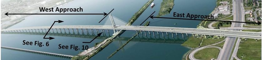
The existing 3.5 km long Champlain Bridge shown
in Figure 1 spans the St. Lawrence River and
connects the city of Brossard to Nuns’ Island which
forms part of the city of Montreal. A companion
structure, 468 metres long and referred to as the
Nuns’ Island Bridge (recently demolished) crosses
the western arm of the St. Lawrence and connects
the southern shore of the St. Lawrence River to the
Island of Montreal. Both structures were constructed
at the same time and opened to traffic in 1962.
The project and its schedule are driven by the
condition of the existing bridge. As reported
elsewhere “…the bridge is quickly approaching the Figure 1: Aerial View of Existing Bridge &Temporary Jetties
end of its useful life. As such, replacement of the
bridge must be expedited to ensure continuous use of the crossing” (Mailhot et al, 2014). In light of its condition, in
December 2013 the Government of Canada announced that it would strive to replace the existing bridge under an
accelerated timeframe by the year 2018. Because of its condition and importance, the existing bridge has undergone
extensive major structural repairs over the years by The Jacques Cartier and Champlain Bridges Incorporated, the
owner and operator of the existing crossing. Pending the bridge’s replacement, monitoring, inspection and major
STR-907-1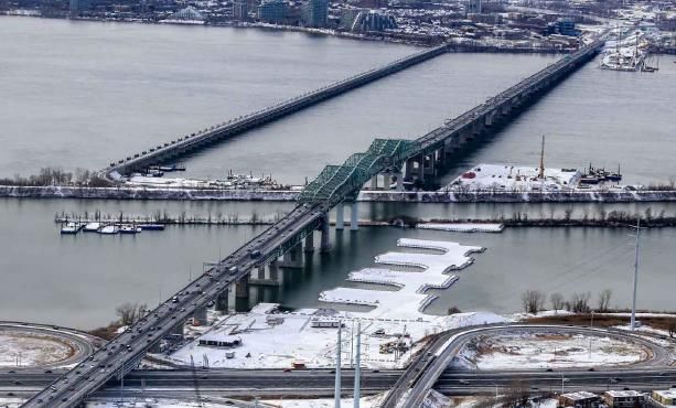
structural interventions over the past few years have increased substantially in order to maintain the bridge in a safe
operating condition.

Under the context described above, the Government of Canada issued a Request for Proposal on July 18, 2014 and
awarded a contract on June 19, 2015 to the consortium Signature on the Saint Lawrence Group to design, build,
operate, maintain and finance the undertaking of the new Champlain Bridge Corridor Project. Procured as a Public-
Private Partnership (PPP), this new project entails a new replacement crossing over the St. Lawrence River in
Montreal and represents one of the largest bridge projects currently underway in North America. Despite its
accelerated schedule and delivery method, the Government of Canada has committed to delivering a modern and
highly durable structure that would meet the transportation requirements of the Greater Montreal region while
meeting the expectations of the community with respect to its architectural quality and visual impact. A number of
the technical requirements prescribed by the Government of Canada to define its expectations and principal
objectives and the Private Partner’s approach to satisfy these are described in the pages below. Figure 2 below
provides a rendering developed on the basis of the Government of Canada’s reference design which also serves to
illustrate the West Approach, the East Approach, the Main Span Tower and Cable Stayed Bridge spanning the Saint
Lawrence River. In this figure, Montreal and Nuns’ Island are located on the left of the figure whereas the City of
Brossard is shown on the right.

              Figure 2: Aerial View Rendering of New Champlain Bridge (Existing Bridge Removed)

2. ARCHITECTURAL REQUIREMENTS

An important facet of the project for which the Government of Canada endeavored to devote proper attention early
in the development stage was architectural quality. The new Champlain Bridge involves one of the largest pieces of
infrastructure in the Montreal area and is considered to be the gateway to Montreal. Accordingly, the Government of
Canada wanted to integrate measures to ensure that the architectural quality expectations for the new Champlain
Bridge would be met. Although various potential schemes were explored to incorporate architectural quality within
a PPP procurement framework (international competition, architectural directives process, competitive dialogue,
etc.), the accelerated timelines and concerns about the ability to preserve the requisite architectural quality elements
and enhancements throughout the delivery process led the Government of Canada to adopt a directives approach
resulting in a precise definition of the most prominent and visually significant features of the main span over the St.
Lawrence Seaway and the approaches of the bridge over the remainder of this major river.

Under this approach, architectural guidelines were developed regarding structural form, architectural lighting and
lighting scenes including highly realistic views from and of the bridge. These guidelines were framed by a
“definition design” such that the government could guarantee to the community that what it displayed during its
public announcements would in fact be delivered, or in other words “What you see is what you get” (WYSIWYG).
As part of its mandate to assist the Government of Canada in the development of procurement documentation, Arup
Canada Inc. retained the services of a world renowned architect (Poul Ove Jensen from Dissing+Weitling) who has
contributed to several notable bridge projects including several cable stayed bridges (Svensson, 2012). The process
of determining the architectural shape of the bridge involved the collaboration of distinguished professionals and
members of the community, a local architectural firm and Government of Canada professionals in order to clearly
establish the rules and expectations in matters of architectural quality and aesthetic enhancement. Measures were
incorporated in the Request for Proposal as well as the Project Agreement’s technical requirements to ensure that the

                                                      STR-907-2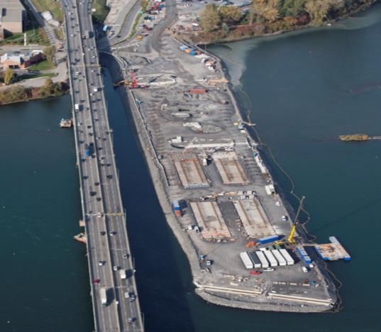
architectural vision set out in the development phase would be preserved in the delivered bridge. This was a key
requirement of the tendering process.

3. STRUCTURAL DESIGN REQUIREMENTS

Considering the importance of the bridge and its extended design life, a number of special structural requirements
were specified by the Government of Canada in addition to the architectural requirements identified above. Some of
these requirements, which generally exceed or expand upon the minimum design requirements prescribed in the
Canadian Highway Bridge Design Code (06 or 14 versions), are briefly discussed below.

3.1 Highway Live Loading

To account for the extended design life, the standard truck load and lane models defined in CAN/CSA S6-06 were
augmented by 10% (i.e. CL-625 increased by 10% equally to all axles to give a CL-685 truck load model). A
special truck load, identified as NBSL-15 was also specified. This vehicle (inspired from a Caltrans P-15 special
truck) represents a total load of 1,796 kN (mass of 183 metric tonnes) distributed over 15 axles as shown in Fig. 3
below. Considering that the potential passage of a truck of this size and magnitude over the new Champlain Bridge
is expected to be a rare event (based on historical special permit requests on the existing Champlain Bridge), the
project requirements allow that this vehicle could travel in a single lane at a reduced speed of 10 km/h or
alternatively, it could straddle two adjacent marked lanes while travelling at 25 km/h. Dynamic load allowances are
permitted to be reduced by the factors identified in Section 14 of CAN/CSA S6-06 and the live load factors for the
special truck are those generally identified in Section 3, Table 3.2 of CAN/CSA S6-14.

The specifications required that the new bridge have three separate corridors (see Fig. 6), with the upstream and
downstream corridors dedicated to highway loading and the central corridor dedicated to a mass transit system,
which could consist of either busses or a light rail system. When operated with buses, the applicable highway
loading would consist of the standard CL-625 load model. However, to accommodate the eventual transition from a
bus system to a light rail system, the highway carriageways were widened to safely accommodate buses running
temporarily within the shoulders. Accordingly, the highway corridors are designed to accommodate 4 lanes of
highway traffic. The north corridor (downstream corridor) was also required to accommodate a multiple-use path
with a net width of 3.5 metres with pedestrian and maintenance vehicle loading as prescribed in CAN/CSA S6-06.

                                   Figure 3 – NBSL-15 Special Truck Loading

3.2 Rail Loading Requirements

Provisions in the Project Agreement (the PPP contract) required that the bridge be designed so that it could
eventually accommodate a light-rail transit system (LRT) or as designated in this project a “Système léger sur rail
(SLR)”. Because the exact type of light-rail transit system was not known at the time the project was tendered (and
is still not confirmed), discussion with the promoter of the eventual light-rail transit system namely, the Agence
métropolitaine de Transport (the promoter is now the Caisse de dépôt et de placement du Québec/CDPQ), it was
decided to adopt Eurocode rail loading meeting the following two train load models (classified LM71 and SW0
models) below.

                                                   STR-907-3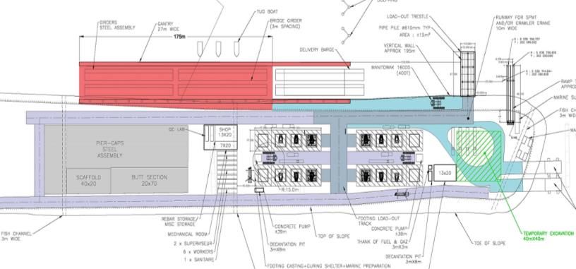
Figure 4a: Classified LM71 Rail Loading                          Figure 4b: Classified SW0 Rail Loading

3.3 Seismic Design Requirements

At the time the Government of Canada (the Authority) was drafting its technical specification in 2014 with the
assistance of its consultant Arup Canada Inc., the applicable Canadian Highway Bridge Design Code in force was
CAN/CSA S6-06 (R2013). Well aware however of the fact that a newer version of the upcoming code would
include major revisions to its seismic design provisions, notably an evolution towards a performance based design
approach, the Authority obtained a draft version of the newer code via CSA International as well as edits to its draft
version via Dr. Denis Mitchell, McGill University, chairman of the seismic design section of the code. Furthermore,
in collaboration with Geological Survey of Canada/Natural Resources Canada and in particular Dr. John Adams a
prominent Canadian seismologist, the Authority was also able to obtain the most recent spectral values available at
the time for the Montreal region (Table 1), which were essential in establishing the basic design parameters for
seismic design. Essentially, the design requirements for seismic design included as a minimum most of the relevant
sections of the draft version of CAN/CSA S6-14, ensuring that the new bridge would meet state-of-the-art
requirements for seismic design. The new Champlain Bridge is designated as a lifeline bridge, and this designation
fits very well the newer definition of such a bridge as defined in CAN/CSA S6-14 which reads “a large, unique,
iconic, and/or complex structure that is vital to the integrity of the regional transportation network, the ongoing
economy, and the security of the region and represents significant investment and would be time-consuming to
repair or replace”. Such a designation requires that the bridge shall be fully serviceable for normal traffic and have
sustained minimal damage under a seismic event having a 975-yr return period and provide limited service for
emergency traffic and be repairable without bridge closure under a large seismic event having a 2475-yr return
period (i.e. 2% probability of exceedance in 50 years).

              Table 1: Horizontal Spectral Acceleration for Seismic Design (Site Class C 5% damping)
                     Period (s)                       475-yr.        975-yr         2475-yr
                                                     10% 50 yr      5% 50 yr       2% 50 yr

                     .2                                 .2040          .3370           .5915
                     .5                                 .1065          .1740           .3090
                     1                                  .0520          .0835           .1470
                     2                                  .0240          .0385           .0675
                     5                                  .0055          .0095           .0175
                     10                                 .0020          .0040           .0060

Recognizing the need to ensure that damage to the bridge under a large seismic event could be repaired (i.e. limit on
concrete strains and limit on excessive inelastic behaviour), the project requirements included the opportunity for the
designer to pursue an “Essentially Elastic Design” approach. If such an approach were adopted, the seismic demands
had to be augmented by 30%. Consistent with requirements for modern seismic design of important bridges, the
specifications required that the designer carryout non-linear time history analysis using a minimum of five sets or
more of relevant time-histories. If less than eleven sets of time histories were used, the maximum response quantity
had to be used, however, if eleven or more sets are used, the mean response quantity can be used. To further ensure
that the design for seismic approach would follow recognized best-practices in the area of modern seismic design of
important bridges, the project requirements also required that the seismic design of the new bridge be peer reviewed
by an independent seismic expert.

                                                     STR-907-4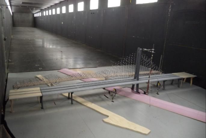
3.4 Wind Loading
Incorporating an asymmetrical cable stayed bridge with a main span of 240 m, a back span of 124 m and a single
slender tower extending some 158 m above high water level, the project requirements incorporated modern best
practice requirements for wind engineering for the design of the new bridge. These requirements included among
others; i) sectional model testing of the deck cross-section with and without traffic at 1:50 scale, ii) stability and
buffeting analyses for completed bridge and critical construction stages, iii) full aeroelastic modelling at 1:150 scale
in both smooth and turbulent flows of the final bridge (with and without the presence of the existing Champlain
Bridge) and iv) full aeroelastic modelling of the bridge at 1:150 scale in both smooth and turbulent flows at critical
erection stages. The Mean Return Interval (MRI) and corresponding design wind speed and averaging times at the
bridge deck level, based on a review of historic wind speeds at the site (including in-situ measurements on the
existing Champlain Bridge) are reported in Table 2 below.
Table 2: Design Wind Speeds (at Deck Elevation)
Condition MRI Averaging U
(years) Time (sec) (m/s)
Construction design 20 3600 27.5
Final design 125 3600 31.0
Aeroelastic Stability - construction 1000 600 41.0
Aeroelastic Stability - final bridge 10000 600 48.0
The analysis for wind loads were carried out by two
highly specialised wind engineering specialty firms,
namely WES WIND Laboratories for the sectional
modelling and The Boundary Layer Wind Tunnel
Laboratory at Western University for the full aeroelastic
wind tunnel testing. With the unexpected passing of Dr.
Raggett (WES WIND Laboratories) in September 2015,
Dr. Peter King, P.Eng. of Western University oversaw
the entire wind study investigations.
Wind tunnel testing showing in the foreground the full
aeroelastic model of the new bridge in its final
configuration and the existing bridge in the background is
presented in Fig. 5. In this figure, it is interesting to note
the height of the new main span tower in comparison to
the existing steel through-truss cantilever bridge. The Figure 5: Aeroelastic Wind Tunnel Testing of Completed
height of the new bridge is in fact limited by the zone of Bridge (The Boundary Layer Wind Tunnel Laboratory –
no obstruction for aircraft landing at the nearby Saint Western University)
Hubert Airport.
4. DURABILITY OBJECTIVES
One of the Government of Canada’s principal objectives for the project as noted above was to ensure the delivery of
a new bridge of a very high quality and endowed with an extended design life of 125-years. To this end, the project
specifications and performance objectives imposed by the Authority included among others the following design
criteria or design features:
Design life of 125-years for all non-replaceable elements (refer to Table 3 below).
Mandatory use of stainless steel reinforcement in strategic locations as detailed below.
Incorporation of a deck waterproofing membrane and high performance asphalt overlay with enhanced
thickness (90 mm vs 65 mm standard thickness in the province of Québec).
STR-907-5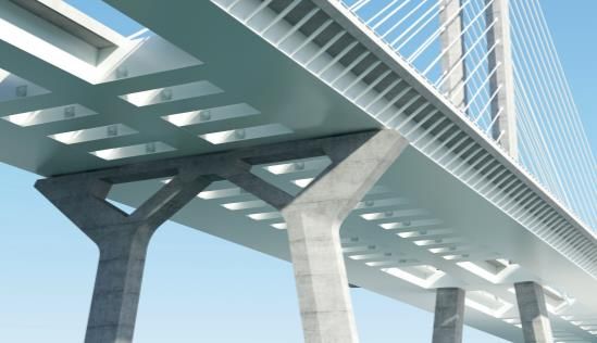
Good deck drainage system including longitudinal carrier pipes and vertical drain pipes extended so as
to discharge close to water level.
Requirement that the Private Partner develop a Durability Plan that demonstrates that the durability
objectives set out in the Project Agreement can be met.
Requirement that the Private Partner undertake time-to-corrosion modelling for concrete components
using state-of-the art modelling techniques.
Fatigue resistance of components to be considered over the extended design life.
Reserve capacity for structure design which allows for the replacement of a cable stay with traffic and
which also accounts for the potential loss of multiple stays in an extreme event.
Limitation on the number of expansion joints; a maximum of only 8 expansion joints is permitted,
including the expansion joints at the abutments. This is in strong contrast to the existing bridge which
incorporates 57 expansion joints.
Incorporation of an efficient system for maintenance access and inspection, for example shuttles within
box girders, elevators within the main span tower shafts, supply of under-bridge-inspection-vehicle and
access devices within the interior of all hollow pier columns as well as maintenance travellers for the
main span and back span for the cable stayed bridge.
Remote controlled inspection system for cable stays.
Stainless steel anchors installed in bridge components to facilitate inspection of the structure using rope
climbing techniques.
Incorporation of a Structural Health Monitoring System including corrosion sensors for concrete.
Requirements to mitigate stray currents and induced currents, particularly in light of the eventual
implementation of an electrified mass transit system.
High performance three-coat paint system for exterior surfaces of structural steel elements and a two-
coat system for all interior surfaces of box girders.
Specific and detailed requirements governing handback conditions of the structure (after the 35 year
concession period), including a detailed assessment of the condition of the cable stays.
Special requirements governing the design of reinforced and prestressed concrete components,
including specific requirements on maximum crack widths and conditions for injection of specific
cracks.
With respect to the design and fabrication of concrete components, of special concern given the owner’s challenges
encountered with respect to the maintenance of the existing bridge’s prestressed concrete girders along approach
spans, the project specifications required the use of stainless steel reinforcement meeting the requirements of British
Standard BS 1.4301, 1.4162 or 1.4362 (similar to ASTM A955/A995M) at the following strategic locations:
100% of all reinforcement in deck slab.
Starter bars for barriers and appurtenances (other bars in barriers consist of galvanized reinforcement).
Outer layer of all external faces of horizontal tie beams at the top of all piers (not applicable in the
Private Partner’s design since the pier cap will be made of steel).
Outer layers of all external faces of superstructure, piers and abutments at and below roadway joints.
Outer layers of all external faces in piers and abutments within 10 metres horizontally of at-grade
roadways up to a height of at least 8 m above the at-grade roadway.
Outer layer of all external faces of tower columns and lower cross-beam from 8 m above the roadway to
the soffit level of the superstructure.
STR-907-6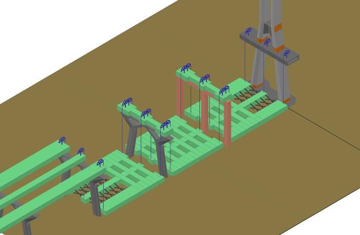
Table 3 - Specified Design Life for Various Components
Component * Design Life (years)
Non-replaceable components
Foundations (piles, pile caps, footings) 125
Substructure (piers, abutments, tower) 125
Superstructure (including deck slab) 125
Replaceable components
Bearings 40
Expansion joints 30
Barriers 50
Drainage system 40
Bridge cables/stays 65
* Partial list
5. SUMMARY OF PRIVATE PARTNER’S ADOPTED DESIGN
Although the project requirements and in particular the definition design dictated the overall shape of the piers,
approach spans as well as the main span crossing over the seaway, the Private Partner was free to establish the
internal configuration of box girders and to select the specific material type for deck slab, superstructure, and pier
caps. The Private Partner was also offered the flexibility of determining the most appropriate span length for
approach spans, provided that spans would be equal to or greater than 65 metres in length and provided that the
bridge would comprise a maximum of eight expansion joints (including the two expansion joints at the East and
West abutments). In its planned final form, the Private Partner’s adopted design which was developed following
close collaboration between the design and construction teams consists of:
For typical approach spans
three independent steel box girders (East bound and West bound highway corridors and central mass
transit corridor) having constant depth of 4 m and typical spans of 80.4 m centre-to-centre of piers.
precast deck panels with wide closure strips reinforced with looped stainless steel reinforcing bars.
W-shaped plated steel pier caps which are secured to the pier shafts by way of post-tensioning (PT
anchors are located inside the steel pier caps and within a cast-in-place concrete bulk head). All post-
tensioning is also internal to the precast pier segments and footings.
hollow precast post-tensioned match-cast pier legs for approach spans.
precast gravity footings (generally 11 m x 11 m x 2 m thick) resting on sound (unaltered) bedrock.
Looped ducts in the footings allow the footings to be connected to the pier shafts by way of internal
post-tensioning. A system of pucks, levelling bolts and tremie pipes allows the footings to be levelled
and uniformly supported by the bedrock.
For cable stayed bridge
asymmetrical cable stayed bridge having a 240 m main span and 124 m backspan. Cable planes are
essentially vertical (as dictated by the definition design) and spaced roughly 12 m on centres.
three steel box girders 4 m deep interconnected with rectangular steel cross-beams.
154.5 m high main span tower (measured from the top of pier cap to top of tower). The main span tower
legs consist of hollow precast segments inclined below the upper cross beam (bow-tie) and cast-in-place
hollow concrete sections for the region located between the bow-tie and the tower tops (refer to Fig. 8).
drilled shaft foundations for back span piers (W01 and W02) as well as main span tower (MST)
foundation. Tower is supported by two 4 m thick pile caps connected with tie beams, each supported by
twenty-one 1.2 m dia. drilled shafts per tower leg. The most heavily loaded drilled shafts are socketed
some 12 m into sound (unaltered) Utica-shale rock.
STR-907-7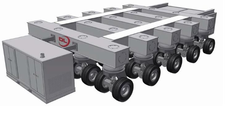
Figure 6 illustrates the typical arrangement for approach spans decks and Figure 7 the typical arrangement for the
substructure. With respect to the main span, Figure 9 shows the general configuration of the asymmetrical cable-
stayed bridge whereas the main span tower is illustrated in Fig. 8. An architectural rendering of the new bridge, seen
from below the deck, is also shown in Fig. 10.

                       21.62 m                                 10.87 m                           17.32 m

                               Figure 6: Typical Approach Span Deck Configuration

                                                                                                               Cast-in-Place Concrete
                                                    Steel

                                                                         154.5 m
                                                    Concrete
                                                    Precast

                                                                                                                    Concrete
                                                                                                                    Precast

       Figure 7: Typical Approach Span Pier                                        Figure 8: Main Span Tower

6. PRIVATE PARTNER’S CONSTRUCTION METHODOLOGY

In order to meet the challenging construction schedule, the Private Partner opted for extensive on-site and off-site
precast concrete operations as well as off-site steel fabrication by Quebec based steel fabricators as well as steel
fabricators based in Spain. Pre-assembly of steel components will occur on site at the West Jetty described below.

                                                     STR-907-8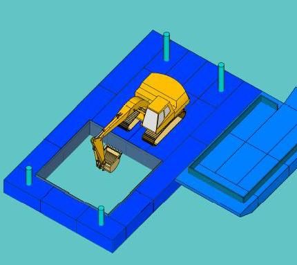
W02            W01                    MST                                      E01
                     80.4              124 m                            240 m                     84.43m
                     m

                                               Figure 9: Main Span Configuration

     Figure 10: Main Span Rendering                                         Figure 11: Main Span Erection
         View from Below Deck

6.1 Temporary Concrete Precasting and Steel Preassembly Facilities

One of the key strategies behind the Private Partner’s construction
approach is the installation of three rock-filled jetties, the principal one
having dimensions of roughly 500 m in length by 100 m in width and
which has been constructed along the western end of the new
Champlain Bridge along Nuns’ Island as shown in Fig. 15a. This large
jetty (West Jetty), which incorporates three fish passages, is used to
install a temporary precasting plant certified to the requirements of CSA             Fig. 12: Self Propelled Mobile
A23.4 Precast concrete – materials and construction. This precast plant                         Transporter
is used to fabricate precast footings, pier starter stems and to
preassemble the first off-site fabricated precast starter segments. The
jetty is also used to preassemble superstructure segments and steel pier
caps. The jetty is equipped with marine load-out and docking facilities
required to transfer prefabricated concrete and steel bridge components
for transport by barge to their final position along the St. Lawrence
River. A custom-built Self Propelled Mobile Transporter (SPMT) with a
capacity of some 1000 tonnes (see Fig. 12) will be used to move precast
foundation units (footing, pier stem and starter segment) to various
fabrication positions within the West Jetty. Lastly, once all bridge
components have been precasted or preassembled on the jetty, the rock
filled structure will be used to facilitate the construction of 6 piers in dry     Fig. 13: Marine Excavation on Barge
conditions (on rock-fill).

The West Jetty is complemented by two other jetties, namely the Main Span Tower Jetty (MST Jetty) and the East
Jetty as shown in Fig. 1. The MST Jetty is currently being used to construct the main span tower footing and will be
used to erect a temporary bent to construct the backspan superstructure on land for eventual hoisting into position by

                                                         STR-907-9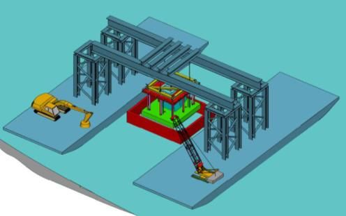
way of strand jacks (Fig. 16). The East jetty, on the other hand is used to
erect piers in the dry along the fingers of the East Jetty. The total length
of jetties (West, MST, East) represents approximately one-third of the
width of the St. Lawrence River at the location of the bridge.

6.2 Approach Span Fabrication

Fabrication of the west approach spans substructure includes the
following principal activities, namely; i) prefabrication of footings and
pier stems, ii) transport of heavy prefabricated segments using the SPMT
to load-out marine facilities, iii) marine excavation using an excavator
mounted on a barge (Fig. 13), iv) water transport of footings and pier          Fig. 14: Erection of Footing and Pier-
stems from the jetty to final destination using a large gantry supported by       Starter Segment using Catamaran
catamaran (Fig. 14), v) final excavation and verification of bedrock, vi)                       Gantry
unloading of the precast concrete pier components to their intended final position, vii) levelling of pier footings
using three-point support pucks installed on the underside of the footing and levelling devices, viii) placement of
tremie concrete to fill the cavity between the bedrock and the underside of the footing elements, ix) adjustment of
geometry facilitated by a cast-in-place joint (below water level) made between the pier stem and the first off-site
prefabricated pier starter segment, x) installation of match-cast pier segments making use of a combination of post-
tensioning bars and post-tensioning cables, xi) installation of a temporary horizontal tie beam at the top of the pier
legs, xii) installation of steel pier caps which are composed of two large preassembled pieces (roughly 25.6 m x
11.4 m each) by way of a large barge mounted crane and xiii) post-tensioning of the steel pier caps to the precast
segmented pier legs. East approach work although similar, involves several spans located on land or accessible by
the temporary East Jetty (see Fig. 1) which simplifies works to some degree.

West approach steel-concrete composite superstructure erection includes the following main activities, namely; i)
installation of a segment of the steel superstructure on a pier which is temporarily supported by steel struts
connecting the superstructure segment to the pier, ii) load out of a preassembled box-girder section, iii) erection of
the preassembled superstructure segment using a large barge mounted crane, iv) making of the splice with the
previously installed steel segment installed over the pier, v) installation of precast deck panels, vi) placement of
closure strip concrete (deck stitches), and vii) deck finishing works.

                                      Load-out facilities
   Pre-assembly area for
    steel superstructure

       Pre-assembly area for            Precasting area
           steel pier caps                for footings

           Figure 15a: West Jetty Plan View                                    Figure 15b: West Jetty Aerial View

6.3 Main Span Erection

Main span erection methodology is currently being developed by the Private Partner in close collaboration with the
St. Lawrence Seaway Management Corporation (SLSMC) to ensure that the main span can be safely erected with
minimal impact to navigation within the St. Lawrence Seaway navigational channel.

                                                       STR-907-10
The erection method developed by the Private Partner
contemplates the construction of a temporary bent on the
MST Jetty. The jetty and the temporary bent will enable
the preassembled backspan to be erected at ground level
and then hoisted into position using strand jacks as shown
in Fig. 16. For erection of the main span, steel segments
will be delivered at the base of the Main Span Tower and
then shuttled along the underside of the cantilevered
superstructure for pick-up by a gantry mounted at the tip
of the cantilever (see Fig. 11). This sequence will be
repeated, with the installation of both temporary stays and
permanent stays, until closure can be made with a
segment of superstructure installed at pier E01. It is
expected that the free end of the superstructure will be Figure 16: Erection of Cable-Stayed Bridge
cantilevered out approximately 203 m from the tower Backspan
erection of the main span. This most critical erection
condition has been verified for aerodynamic stability
through wind tunnel testing.
7. CHALLENGES AND OVERALL PROJECT STATUS
Given the fast-track nature of the project, one of the major challenges encountered involved the need to ensure that
the advancement of the design would be able to meet the aggressive project construction schedule considering the
elaborate design review process which was integrated into the Project Agreement and which includes reviews by the
independent design checker, the Authority and its Owner’s Engineer, reviews by various stakeholders as well as
reviews and the issue of certificates by the Independent Engineer.
Furthermore, in light of the condition of the existing Champlain Bridge, the Project Agreement (which governs all
aspects of the construction and delivery of the new Champlain Bridge) imposes strong incentives so as to ensure that
the new Champlain Bridge will be delivered by the required target substantial completion date which is set as
December 1, 2018. Very important liquidated damages in the amount of $100,000 per day and $400,000 per day are
set for late delivery after Dec. 1 and Dec. 8, 2018 respectively. The construction status of the new Champlain Bridge
proper, the most important component of the project is summarized below.
7.1 Current Status
New Champlain Bridge Construction Status as of April 18, 2016:
Design of the overall bridge (West and East approaches and Cable Stayed Bridge) is approaching 100%.
The West Jetty, MST Jetty and East Jetty are completed.
Eight footings have been completed at the West Jetty and the temporary precast plant used to fabricate them
has received CSA certification.
All drilled shafts (42 in total) for the MST have been completed and the South and North pile caps have
been cast.
Marine excavation has begun at the location of two piers (W10 & W18).
Drilled shaft foundations at the West Abutment and East Abutment have been completed.
Drilled Shaft for two piers along the East Approach (E07 & E10) have been completed.
Offsite fabrication for the pier segments of the main span tower and steel superstructure has begun.
STR-907-11Additional information regarding the project and its status can be found at Infrastructure Canada’s web site
(www.infrastructure.gc.ca/nbsl-npsl/index-eng.html) and the Private Partner’s web site (www.newchamplain.ca).
Real-time cameras monitoring the construction activities can also be viewed at:
http://www.nouveauchamplain.ca/chantier/chantier-en-direct/.
7.2 Upcoming Works
It is expected that by the summer of 2016, the main span tower will be constructed to a height of some 35 metres
above water level. It is also expected that a number of piers will have been constructed and would be ready to
receive superstructure components. By the end of 2016, it is expected that erection of the steel superstructure for the
west approach would have begun, the main span tower will have reached a height of some 45 metres above water
level and the first segments of the Cable-Stayed Bridge back span will have been erected.
In summary, almost all key construction activities would have been initiated, thus serving to confirm that the new
Champlain Bridge can be delivered as planned.
ACKNOWLDEGEMENTS
A project of this size and complexities requires the contribution of a number dedicated organizations, firms and
individuals. The author takes this opportunity to acknowledge the participation of the following companies and
firms acting in various capacities:
Owner: Government of Canada
Private Partner: Signature on the Saint Lawrence Group
Designer: SNC-LAVALIN, TY LIN International, IBT (International Bridge Technologies)
Owner’s Engineer: Arup Canada Inc.
Architect: Poul Ove Jensen/Provencher et Roy
Independent Engineer: Stantec/Ramboll Joint Venture
REFERENCES
Van der AA, Hans, ed., 1962. The Champlain Bridge – A Photographic Record, Porcupine Publications Limited,
Montreal, Quebec, Canada.
Mailhot, G., Brazeau, M. and Jarry, V. 2014. New Bridge for the Saint Lawrence, 9th International Conference on Short
and Medium Span Bridges, Canadian Society for Civil Engineering, Calgary, Alberta, Canada, 11 p. Electronic
proceedings.
Canadian Standards Association 2006. CAN/CSA S6-06 Canadian Highway Bridge Design Code. CSA International.
Svensson, H. 2012. Cable-Stayed Bridges – 40 Years of Experience Worldwide, 1st edition, Ernst & Sohn GmbH,
Germany.
STR-907-12You can also read