Historic Danube Bridges in Budapest
←
→
Page content transcription
If your browser does not render page correctly, please read the page content below
Historic Danube Bridges in Budapest
Miklós Iványi
Prof., Budapest University of Technology and Economics, Hungary

1.      The unique instructional locality of bridgework: the bridges of Budapest

     “The bridge is an engineering establishment, which leads roads, railways, trails,
pathways canal or the pipeline of public-utility works, through an obstacle (river, channel,
valley, or another road).”
     This definition - given from an encyclopaedia – luckily seems to be incomplete. After all
a well designed bridge can act as a work of art of a city or of a landscape. Think of the Tower
Bridge in London, the Charles Bridge in Prague, or to mention Hungarian national examples,
the viaduct in Veszprém, and the “bridge with nine eyes” in Hortobágy.
      It is more significant in case of Budapest: the landscape is the most important factor of
the composition of the city. The main constitutive parts of this townscape are the bridges,
which build a uniform system, and through this they connect the plain of Pest and the hills of
Buda into a homogeneous whole, and dominate and decorate the Danube in the heart of the
city.
    Several forms of bridges can be imagined; the wonderful thing in the bridges of
Budapest is that they were built always according to the demands of the era, to the
harmonically matching, and always from an appropriate distance from the next bridge, trying
to match the others, but still not completely copied.
      Everyhow, the bridges are creations of an active human being. They are born from the
dialectical interaction of demands and the financial-technical facilities. The demands are
determined by the era (the level of the advancement of the society) the place (cultural
environment, ethnic) and the active human respectively the humans who take a
determinative part in the constitution; the facilities are characteristic for the place, the era and
for the creator. According to this the constitutions (bridges) will be characterised by the style
of the era, the place, and the individual style of the builder. The declaration of this is
important, because the presentation of the bridges can only be complete through these three
rolls.
     The “form follows function” principle is already hundred years old, the union of
connotation and shape as the basic condition of the esthetical effect. It will be shown, that
the bridges of Pest meet these requirements.
     The function of the products, its essence will be richer if they are put into connection
with each other. In each product the rate of the application function and the esthetical
function varies. If the functional expansion is necessary in respect of both, the aesthetics and
practice, and if they also match to each other due to the environmental proper, the
connection will mean enrichment in every aspect. Each of such connections, which justify
each other, means already some kind of harmony alone. It wakes the experience of accord.
     Some establishment on the bridges:
•    Following the streamline of the Danube, in the east the river is broad, its bed is full of
     islands. The hills are far on the right bank – broad, deck bridges were built according to
     the plain (Árpád Bridge, Margaret Bridge). As we go on to the south, the river gets
     narrow, the banks are fully built-up, the hills of Buda border sheer the river. The balance
     between the two banks are provided, by suspension bridges with high pillar (Castle Hill –
Chain Bridge, Gellért Hill – Elizabeth Bridge), or by bridges, of which shape follows the
others (Gellért Hill – Szabadság Bridge). Following the river, the horizon gets broader
again. This mustn’t be disturbed by a structure above the bridge-deck – here comes
again a deck bridge (Petőfi Bridge).
• The maximum distance from where the presence of people can be sensed is about 1000-
1200m. Therefore this is the biggest unit of the urban scale. This seems to be justified by
the rhythmical chain of the bridges.
In this chain the distance between the Chain bridge and the Margaret Bridge is an
exception. This is almost twice as the actual distance, and the visual connection between
these bridges seems really more uncertain. (But a mention must be made, that from
some aspects the dominant block of the Parliament secures the advantageous dividing of
this distance. Both statement will be proven to be true not only by day but by night as
well.) The location of the bridges was determined of course principally by the traffic
demand, but the above-mentioned rhythm made them possible to be a part of an
esthetical human environment.
• All of our bridges over the Danube are symmetrical to the streamline and to the vertical
plane of their longitudinal axis too.
The symmetry used to be deemed, already from Platon, to be one of the most important
criteria of the fineness. Later the demand on variedness appeared in engineering constitution
as well. But the variedness can only be pleasant if it meets symmetry and order, what makes
it easier for us to comprehend the variedness; otherwise the vision will get disturbing,
demanding.
2. The bridges of Budapest-part of the World’s Heritage
The bridges take part mainly with their functions in a city figuration; with their
appearance and monumental build-up, they became so important parts of the citypanorama,
that they characterize Budapest more than any other building. In the heart of the city four
bridges crosses the Danube: the Margaret Bridge, the Chain Bridge, the Elizabeth Bridge
and the Szabadság Bridge. From these the last three just at the Castle Hill and the Gellért
Hill take a main part in the vertical articulation of the capitalpanorama. These three bridges
are at the inner, narrow part of the Danube and they quasi convey between the hills and the
plain. The Margaret Bridge matches into the expanding cityscape. It follows the landscape
with calm, simply lines and represents the expanding dimensions. This engineering
construction is an essential part of the city. It closes the expanding part of the Danube still it
allows a view to the outer part of the city. [Gáll, 1984]
The Chain Bridge is one of Budapest’s most beautiful architectural construction, this is
the most harmonic of all, it has the most intimate effect. Both, the old and the new Elisabeth
bridge shows airiness, the Szabadság Bridge combines aesthetics and technical curiosity,
while Margaret Bridge represents safety. No other city in the world has bridges with so
different characters. We can adjoin without any confidence, that each of the bridges is a
tailor-made construction.
Our previous statements are proven by the fact, that the Castle-area and the Bank of the
Danube was taken to the World’s Heritage in 1987.
Along its long history a lot of natural formation and human construction have come into
existence, which are extraordinary stations in the development of the human culture. But
these values can be damaged or evanished through the passing of the time and by the
harmful actions of the human. That is why the “Convention Concerning the Protection of the
World’s Cultural and Natural Heritage” was established by the UNESCO in 1972. It’s mainaim is the protection of the cultural and natural heritage of the mankind. [Nagy, Buris,
Domina, 1998]
2.1 The criteria of the admission
To be a part of the World’s Heritage, a natural or a cultural value has to meet some
requirements.
The Castle area and the Bank of the Danube have been taken to this heritage according
to criteria (II.) and (IV.):
“(II) the important stations of the human culture – in respect of a historical era, or a
cultural region in the world - from the point of view of the development of the architecture, the
technique, the arts or the cityscape planning;
(IV) a building type, architectural or technical working-out, or extraordinary landscape
which represent important stations of the history.”
A chapter of the proposal with the title “The city of bridges” deals with bridges:
“From the top of the Gellért Hill, the vision of hills and plane and the chain of imposing
bridges that connect the two part of the county, provide an impressive scenery. The first
bridge between Buda and Pest, the Széchenyi Chain Bridge is the oldest constant erection
over the Danube from the bridge of Regensburg (middle-age) to the chop of the river. It was
built by Adam Clark according to the plan of Tierney William Clark from 1839 to 1849 done
on commission of István Széchenyi. The two thousand tons structure wasn’t even ready
when the withdrawing Austrian army wanted to blow it up. But the bomb hurt only the colonel
who gave the order for the bridge to be blown. The classicist tunnel through the Castle hill
was finished in 1857, next to it the exact copy of the Wohlfart cable-car can be found.
The Margaret Bridge (built from 1872 to 1876) was designed by the French engineer
Ernest Gouin. It was also built by French, Eiffel participated in it as well. From this bridge led
the first way to the Margaret Island, which was named after the daughter of Béla, IV. The
king was afraid of a return of the Tatars, in his pledge he devoted his daughter (1242-1271)
to a nun. He built her a monastery a church and a small hospital on the Island of the Conies.
A detailed picture of the life on the island is provided by the record of the testifier examiners,
who came after the death of Margaret from Rome.
The third bridge in time, the Szabadság Bridge (originally named after Francis Joseph)
is a steel structure with triumphal arch. Even before the turn of the century, the Elizabeth
bridge got ready. This led the east-west axis of the middle-age Pest to Buda, where it meets
the Saint Gellért Waterfall. The once fancy steel structured chain bridge spanned over the
Danube with one span. Just like the others, this bridge was also blown up in 1944. It was
rebuilt with modern details but original character in 1964.”
It can be mentioned as a comparison, that besides the steel bridges of Budapest among
the 507 accepted places of the “World’s Heritage” 1998, there is only one steel bridge, the
Coalbrookdale “Ironbridge” in Great Britain.
3. Case study: The "Széchenyi" Chain Bridge
3.1 Building the bridge in 1839-1849
The first suspension bridges of Hungary were built during the first half of the nineteenth
century. Of them the "wire bridges" built in Pozsony and Budapest are of interest from a
historical aspect, too. Both of them were made by the craftsman F. Anton of Vienna in 1825and 1826 using own-made cables. The "wire bridge" of Budapest had a length of 22 m and it
was used up to 1875 in the Városliget (Town Park).
The first really large iron bridge in Hungary was the Lánchíd (Chain Bridge) spanning
the Danube and providing a link between Pest and Buda. The idea of construction occurred
already at the end of the eighteenth century but the beginning of the construction dragged. At
last the matter was encouraged by the great leader of the Hungarian reform period, István
Széchenyi, and the construction could have commenced according to the plans of the British
W. T. Clark and supervised by Á. Clark. This activity and the whole life-work of Széchenyi
intended to make Hungary prosperous, were acknowledged by the succeeding generation by
naming this worldfamous bridge after him [Clark, 1852-53], [Iványi, 1992].
The Lánchíd, inaugurated in 1849, with its 202 m long centre span was one of the
largest bridges of that period, constituting the first permanent bridge spanning the Danube
River. The decorated pylons radiating strength were constructed of stone. The forged chains
and suspension bars were produced in England, the cast iron cross girders were
manufactured in Hungary. The wooden deck was stiffened by Howe girders combined with
cast iron members formed as railings on both sides.
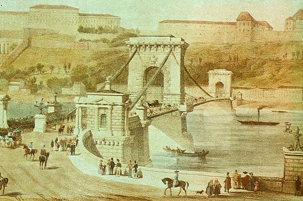
The matchless beauty of the Chain Bridge was met with great success the world over,
and it became one of the symbols of the Hungarian capital and its Danube-bank (Fig. 1).
Figure 1. General view of Chain Bridge
3.2 Rebuilding the Bridge in 1914-1915
The oldest fixed bridge across the Danube at Budapest, after remaining in service
unchanged for more than sixty-five years, had been rebuilt by complete reneval of the cables
and suspended structure and reinforcement of the anchorages [Beke, 1924]
While the old structure excelled among the bridges built in the same period, not only for
its beauty but also for its more highly developed construction [Clark, 1852-53], its capacity
was inadequate for modern traffic needs. This fact, together with defects arising from the
deficiency of bridge theory and design at that early time, resulted in various troubles. In the
course of years many of the cast-iron floor-beams cracked. The anchorage of the cables and
their support on the towers required much attention. The bridge was so flexible as to developalarming oscillation and sway under heavy crowds or in strong winds. Eventually,
reconstruction of the bridge became inevitable.
It was considered essential to maintain the original appearance of the bridge in the
reconstruction. Many old traditions are connected with the bridge. Moreover, the structure
had become virtually a part of the landscape, its beauty and that of the river and
surroundings blending most harmoniously. Therefore, the principal form of the bridge was to
be preserved and no visible alternation was to be produced in the towers and anchorages,
which are of magnificient arhitecture and are in excellent preservation. As regards the
superstructure, however, it was not practicable to retain (and merely strengthen) the
suspension chains, trusses and floor, and their entire replacement was necessary. Except for
towers and anchorages, therefore, a completely new structure was to be built, to outlines of
the old bridge.
Just as in the old bridge, the new carrying members are two superimposed eyebar
chains on either side of the roadway, with stiffening trusses suspended by hangers. The new
hangers are suspension members made of two tees, with bolt hangers at the lower ends
supporting the ends of the new floorbeams in flexible manner. The floorbeams are plate
girders. A central system connects the bottom chords of the stiffening trusses.
The new floor was proportioned for a live-load of 24 tons trucks. For the stiffening
trusses and chains a uniform live-load of 400 kg per square m was adopted. It was
unnecessary to provide for electric cars and very heavy trucks as these can cross by way of
three other highway bridges elsewhere in the city, which have wider roadways. In the
Széchenyi bridge the original width of the roadway could not be increased, as the suspended
structure passes through the portals of the towers.
The suspension chains of the old bridge were of wrought iron, and the stiffening trusses
of wood. In the new structure these parts and lateral system are of high-carbon open-hearth
steel, of ultimate strength 3600 - 4500 kg per square cm and minimum elongation 20 per
cent in 200 mm. Other parts of the structure are of common (soft) steel, of ultimate strength
3300 - 3600 kg per square cm (and corresponding minimum elongation 28 to 22 per cent),
except that the tower and anchorage saddles are steel castings. Unit stresses of 1400 kg per
square cm for the hard steel and 1 100 kg per square cm for the soft steel were adopted for
the proportioning.
On account of the limitations imposed by the old structure as already mentioned, the
new roadway width, including the curbs (within which cable ducts are inclosed) is only 6750
mm; the cables or suspension chains are spaced 8028 mm apart.
The new chains are of much larger section, however, each chain consisting of
alternately 12 and 13 bars 360 x 34 mm (as compared with 10 and 11 bars, 260 x 25 to 30
mm). The cross-sectional area is thus increased by more than 60 per cent, and the strength
still more on account of the higher quality of the metal.
At the supports of the old chains on the towers there was no evidence that the saddles
ever moved. The new saddles have been so detailed that it is believed that they will move
under load and temperature variations without excessive resistance. Upper and lower chains
have separate supports and move independently. At the front of the abutment, where the
chains change directions as they enter the tunnel leading to the anchor bed plates, cast-steel
rockers (supporting the two chains separately) make provision for horizontal movement due
to stretch of the anchorage portion.
The new anchorage arrangement makes the anchor members accessible and
distributes the load. In the old structure the anchor chains were almost inaccessible and
therefore liable to injury by rust, and excessive load was thrown on the masonry at the edge
of the chain tunnel. The arrangement now is similar to that in the Elizabeth bridge at
Budapest, designed about twenty-five years ago.The stiffening trusses are quite similar in outline to the old wooden trusses. On account
of the limits imposed by the old masonry towers, it was not possible to make the trusses
continuous over main and side spans, as applied in the Elizabeth bridge, and therefore
independent trusses are used. The truss depth is 1/63 of the main span length; it was not
possible to go as high as the customary ratio of about 1/50 without radically changing the
external appearance of the bridge.
Support for the stiffening trusses and lateral system at piers and anchorages was
provided by cutting into the masonry; the old wooden trusses were not supported at these
points.
Extensive foundation was necessary at the abutments, since increased sliding
resistance had to be provided on account of the increased chain pull. To avoid changing the
appearance of the anchorages this reinforcement had to be provided below river level; and
as the river profile made it impracticable to built buttresses at the front of the anchorage,
extensions of the foundations were built on either side of the anchorage, below ground level,
bounced to the original anchorage foundations.
A line of pneumatic caissons was sunk along either side of the foundation and
connected to it by means of reinforced-concrete extensions which are notched into vertical
recesses cut in the old masonry.
In carrying out this part of the work the caissons were sunk first, as the work here had to
be carried below the level of the old anchorage footings. The concrete cap work was done
under protection of the cofferdam formed by the caissons, after the joints between the
caissons had been sealed by concrete keys sunk under pneumatic pressure. The whole
foundation extension is so reinforced and joggled together as to insure the integral action of
the mass.
In the demolition of the old superstructure and the erection of the new, fixed falsework
was employed in all three spans. The main-span falsework contained three truss-span
openings for navigation.
All falsework piles had to be removed before the breaking up of the ice in the Danube,
and this limited the entire program to the short period March to December, 1914. This rapid
construction was successfully accomplished. Floating falsework was used for all remaining
work, including the erection of the stiffening trusses in the main span, done in the following
year. In November, 1915, the new bridge was opened to traffic, after twenty-one months'
interruption.
3.3 Reconstruction the Bridge in 1947-1949
World War II. resulted in a tremendous destruction among the bridges of Hungary. The
most painful loss was the demolition of the road and railroad bridges of Budapest. Due to the
shortage of materials the reconstruction began under very difficult condition in May, 1945. In
spite of this, the traffic connection has not been interrupted even for one day over the
Danube and the Tisza since the winter of 1945/46. By strenuous labour the reconstruction of
the Szabadság-, the Margaret-, and the Chain-bridges was achieved and they were open for
the traffic by 1949.
The reconstruction of the oldest permanent bridge of the capital was not urged by traffic
necessities but rather by traditional reasons. The reconstructed bridge was inaugurated in
1949, on the centenary of its "birthday". It was reconstructed in its original shape but its
bearing capacity was slightly increased and its carriageway widened from 5.45 m to 6.45 m.
The stiffener and the deck was mainly reconstructed but about 50% of the salvaged chains
were reused after a cold flattening (Fig. 2.).Figure 2. Schematic drawing of the Széchenyi Chain Bridge
3.4 Repairing the Bridge in 1987-1988
During the time after the post-war reconstruction of the Danube bridges, the intensity of
traffic was multiplied due to the magnitude of the applied load and the number of vehicles.
The influence of the developed loading was augmented by the salting of roadways, started in
1964. Due to this fact and to the catastrophe of the Reichsbrücke in Vienna in 1976, the
controlling of the bridges over the Danube in Budapest was initiated, which otherwise was
also necessitated by previous service-life of 20-25 years (at the original elements much
more!).
3.4.1 Thickness Measurements of the Eye-bars
The first task in connection with the reconstruction of the Chain Bridge was to determine
the minimum cross sectional area of the bunches of chains consisting of 12 or 13 eye-bars,
damaged by the corrosion. The corrosion was the stronger in the anchorage member,
therefore the examination was restricted only on the first eye-bars [Szittner, 1991].
The measurements in the gaps of 29 mm between the eye-bars could be initiated, when
the lateral surface of the eye-bars was sandblasted with a special sandblast-head developed
especially for this purpose. For the measuring of the thickness, a special monitoring system
was developed, by help of which the determination of the residual thickness remaining after
the corrosion damage of the eye-bars in 7 places simultaneously along their height of 38 cm
was possible. The essential part of the instrument is a closed frame fixed to a rod at its lower
end, and connected removable and easily re-adjustable at its upper end. The measuring
springs are coupled to the frame-columns tilted towards each other so that the free distance
between the feeler-rollers at the ends of the measuring springs should be about 15 mm. Onthe bottom of the measuring cantilever springs, the resistance strain-gages are bonded on
both sides at the clamping. When the measuring instruments together with the measuring
springs were adapted on the eye-bar to be measured, the measuring springs became
deformed as cantilever beams according to the thickness of the eye-bar. The deformation is
directly proportional to the bending moment in the clamping points of the cantilever, or to the
strain of the exterior fibre due to the moment.
The seven measuring-circuits for thickness measurements were connected to a
computer-controlled measuring system, which monitored, collected, processed and recorded
the measuring results in succession. Before the processing of the measuring results, and
even at the greater time-distance between the measuring monitoring, the measuring-circuits
were calibrated.
The thickness measurement was placed on the individual eye-bars in succession, and
the thickness was measured at a distance of 5-25 cm depending on the condition of the eye-
bars. After each data entry, the seven results (thickness) were printed out in mm-
dimensions, then the remained cross-section area of the examined eye- bar was determined
and at last this remained area was expressed in the percentage of the nominal cross-
sectional area, too. By this method, it was possible to determine the minimum cross-sectional
area in every eye-bar and the minimum active area in every bunch of bars, respectively.
On the basis of about 40000 measurement data, it was stated that the weakest cross-
sectional area of the anchorage elements among the 2 x 2 bunches of eye-bars on the Buda
and Pest sides could be found:
in the northern bottom bunch of chains on the Buda side, and in the southern upper
bunch of chains on the Pest side, where the cross-sectional area attached by corrosion was
91 or 95% of the nominal cross-sectional area.
In the weakest eye-bar, the damaged cross-sectional area was 80% of its nominal area,
which fact indicates the importance of the bridge supervision and maintenance, because the
bridge cannot bear any more a corrosion damage like this one. Making known the results of
thickness measurements, we suggested that the effective cross-sectional area of the bunch
of chains should be reckoned with by the 0.90-fold value of the nominal cross-sectional area
in the course of bridge controlling calculation. The instrument was devised in the workshop of
our Department with the direction of Mr. L. Kaltenbach, while the computer-based system
was developed by Dr. M. Kálló.
3.4.2 Load Test
In course of the reconstruction of the Chain Bridge, there were two load tests conducted
[Szittner, 1991]. In the first load test, the suspension forces, and the load-distribution effect in
the stiffening girder were determined. With the second load-test, the deformation of the
bridge, the load-bearing capacity of the supporting chains and individual eye-bars, and the
stress-condition of the stiffening girder, respectively, were examined.
The first load test was performed at night. The bridge was loaded by lorries weighing 20
tons each and placed at a distance of 7.5 m from each other.
The second load was prescribed for the Chain Bridge by the Bridge Department of the
Ministry of Transport (service load). This load consisted of a distributed load involving 18
kN/m (buses), and 0.5 kN/m (passenger cars) taken alternatively for each 24 m long section
in the full width of the bridge (2 lanes), which load corresponds to a distributed load of 13.0
kN/m considering the dynamic factor with respect to the main girder and the stiffening girder.
This load was applied with lorries weighing 200 kN each put behind each other in two queues
and close to the curb so that the measurement of deformation (levelling) could be performed
in the longitudinal axis of the bridge. This load was substantially smaller than that applied
with the first load test.In the course of the first load test, by the effect of the load applied in both the middle-
and the side-span, respectively, there were experienced smaller forces and a less unequal
load distribution in the hangers than it was expected without any previous calculations.
Therefore the measurements were repeated but practically no deviation was detected.
Controlling the measurement results, a method of approximate calculation was
elaborated by Assoc. Professor Dr. F. Papp briefing the essential concept of this method
[Papp, 1991]. By using the method of computer simulation, the bridge was substituted by a
planar framework of bars stiffened by beams, where - of course - a theory of second order
was applied for calculations. With the second load test, the calculated network was modified,
first of all, by reckoning with the brake structure in the middle of the bridge.
The results of the computer simulation were plotted in a formatised layout (Fig. 3.).
Figure 3. Results obtained by the method of computer simulation.
When the middle span is loaded (load position No. 10), not only the hangers of the
loaded middle span but also those of the side-span take part simultaneously in load bearing,
though smaller forces arise in the side-span than in the loaded middle one.
The theoretical examinations were extended also for those of the suspension forces due
to the dead-load. To analyze this problem, after the application of rated dead-load of 189 kN
on the hanger No. 42 by computer simulation, a reduction of 7.8 mm in the length of hangers
was entered with the help of a force of 30 kN. According to calculations, this operation
induces considerable suspension forces only in the manipulated hanger (100%) and in the
two adjacent hangers suspended on the same chain (up to 50%). These two latter forces, of
course, are of reversed sign as compared to the induced force mentioned above. As a
consequence of the results obtained, the suspension forces can be controlled or regulated
easily by hydraulic operating jacks. This relatively not too high sensitivity made possible the
simple change or adjustment of the suspending spindle of the short hangers in the middle
and at the end of the bridge. In the course of the second load test, the vertical displacements
of the bridge were measured at the middle of the side-span and in the sixths of the middle
span. The displacements were measured by levelling in the longitudinal axis of the bridge
and by photogrammetric method on the northern main girder. As measuring points for
photogrammetry, the chandeliers of the decorative lighting were switched on.
In the following Table presented here the deflection values calculated and measured,
respectively, at the different load positions by photogrammetric method and with the help oflevelling were compared with each other. Deformation values obtained by levelling and
photogrammetry, respectively, deviate from each other to a small extent, which can be
explained by the not exact marking of the photogrammetric points.
The difference between the values of the calculated and measured vertical
displacements will amount to 25 - 30% within the loaded spans, while it will amount to 40 -
60% within the unloaded ones. This can probably by attributed to the fact that the
contribution effect between the floor system and the stiffening girders cannot be estimated
with a required accuracy.
Table. Deformation [mm] measured by levelling (N), photogrammetric (F), and calculation (Sz).
On the basis of the evaluation of those said above, i. e.
• the reduction of about 10% in the cross-sectional area determined from the measurement
results,• from the stresses arisen in the chain, the hangers and the stiffening girder,we agreed
with the proposal of the UVATERV in our report, according to which: further traffic can be
allowed for loads prescribed by the Ministry of Transport (buses + passenger cars) in
case
• the unrusting and re-painting of the bridge steel structure,
• the repair of the anchorage chamber's insulation
• the replacement of the deck-slab, and
• the repair of the masonry have been performed.
However, we should like to draw the attention to the importance of the supervision and
maintenance of the bridge, and especially to check the chains with special care, because in
case this task would be neglected, a newer attack of corrosion damage on the chains could
result in the reduction of their load-bearing capacity to such an extent which would endanger
the serviceability of the bridge.
4. Summary
The inhabitants of Budapest have always been proud of the bridges of the capital which
suited fine by their appearance and outline the scenery of the Danube-banks. Only one
permanent bridge linked the two river banks 150 years ago: the Széchenyi Chain-bridge.
5. References
[1] Beke, J. (1924): Rebuilding the First Budapest Suspension Bridge. Engineering
News-Record, Vol. 92, No 26. 1924. June 26, pp. 1096-1099.
[2] Clark. W.T. (1852-53): An Account of the Suspension Bridge across the River
Danube. London, John Weale, 59, High Holborn.
[3] Gáll, I., (1984), A budapesti Duna-hidak – Danube bridges of Budapest (Hungarian),
Műszaki Könvykiadó, Budapest,
[4] Iványi, M. (1992): The Széchenyi Chain Bridge. Proceedings, Int. Conference
"Bridges on the Danube", Vienna-Bratislava-Budapest, Sept. 7-12., 1992.
[5] Nagy, É., Buris, L. and Domina, I., (1998): A Világörökség - The World’s Heritage
(Hungarian) (Az ember legféltettebb kulturális és természeti értékei), Gulliver
Könyvkiadó, Budapest,
[6] Papp, F. (1991): Application of planar modelling of bar structures during the
examination of the Széchenyi Chain Bridge. Periodica Politechnica, Sec. Civil Eng.
Vol. 35., pp 311-317.
[7] Szittner, A. (1991): Theoretical and experimental examination performed during the
latest repairing of the Chain Bridge. Periodica Politechnica, Sec. Civil Eng. Vol. 35.,
pp 295-310.You can also read